EP3321543B2 - Internal combustion engine piston ring - Google Patents
Internal combustion engine piston ring Download PDFInfo
- Publication number
- EP3321543B2 EP3321543B2 EP16821021.9A EP16821021A EP3321543B2 EP 3321543 B2 EP3321543 B2 EP 3321543B2 EP 16821021 A EP16821021 A EP 16821021A EP 3321543 B2 EP3321543 B2 EP 3321543B2
- Authority
- EP
- European Patent Office
- Prior art keywords
- piston ring
- arcuate surface
- chamfered edge
- chamfered
- radius
- Prior art date
- Legal status (The legal status is an assumption and is not a legal conclusion. Google has not performed a legal analysis and makes no representation as to the accuracy of the status listed.)
- Active
Links
- 238000002485 combustion reaction Methods 0.000 title claims description 26
- 230000002093 peripheral effect Effects 0.000 claims description 38
- 230000001154 acute effect Effects 0.000 claims description 3
- 239000007789 gas Substances 0.000 description 32
- 230000006835 compression Effects 0.000 description 25
- 238000007906 compression Methods 0.000 description 25
- 230000000052 comparative effect Effects 0.000 description 10
- 230000000452 restraining effect Effects 0.000 description 8
- 238000005549 size reduction Methods 0.000 description 7
- 239000000463 material Substances 0.000 description 4
- 230000009467 reduction Effects 0.000 description 4
- 238000005259 measurement Methods 0.000 description 3
- 238000000034 method Methods 0.000 description 3
- 238000011160 research Methods 0.000 description 3
- 230000015572 biosynthetic process Effects 0.000 description 2
- 238000010586 diagram Methods 0.000 description 2
- 230000000694 effects Effects 0.000 description 2
- 238000002347 injection Methods 0.000 description 2
- 239000007924 injection Substances 0.000 description 2
- 101100494367 Mus musculus C1galt1 gene Proteins 0.000 description 1
- 101150035415 PLT1 gene Proteins 0.000 description 1
- 229910000831 Steel Inorganic materials 0.000 description 1
- 230000003466 anti-cipated effect Effects 0.000 description 1
- 230000001680 brushing effect Effects 0.000 description 1
- 230000015556 catabolic process Effects 0.000 description 1
- 239000000567 combustion gas Substances 0.000 description 1
- 238000011109 contamination Methods 0.000 description 1
- 230000003247 decreasing effect Effects 0.000 description 1
- 238000006731 degradation reaction Methods 0.000 description 1
- 238000006073 displacement reaction Methods 0.000 description 1
- 239000000446 fuel Substances 0.000 description 1
- 239000002737 fuel gas Substances 0.000 description 1
- 238000000227 grinding Methods 0.000 description 1
- 239000010687 lubricating oil Substances 0.000 description 1
- 230000007246 mechanism Effects 0.000 description 1
- 239000003921 oil Substances 0.000 description 1
- 238000005498 polishing Methods 0.000 description 1
- 230000002265 prevention Effects 0.000 description 1
- 230000008569 process Effects 0.000 description 1
- 238000012545 processing Methods 0.000 description 1
- 238000005096 rolling process Methods 0.000 description 1
- 238000007789 sealing Methods 0.000 description 1
- 238000007493 shaping process Methods 0.000 description 1
- 239000010802 sludge Substances 0.000 description 1
- 239000000243 solution Substances 0.000 description 1
- 239000010959 steel Substances 0.000 description 1
- 238000012360 testing method Methods 0.000 description 1
- 230000007704 transition Effects 0.000 description 1
Images

Classifications
-
- F—MECHANICAL ENGINEERING; LIGHTING; HEATING; WEAPONS; BLASTING
- F16—ENGINEERING ELEMENTS AND UNITS; GENERAL MEASURES FOR PRODUCING AND MAINTAINING EFFECTIVE FUNCTIONING OF MACHINES OR INSTALLATIONS; THERMAL INSULATION IN GENERAL
- F16J—PISTONS; CYLINDERS; SEALINGS
- F16J9/00—Piston-rings, e.g. non-metallic piston-rings, seats therefor; Ring sealings of similar construction
- F16J9/12—Details
- F16J9/20—Rings with special cross-section; Oil-scraping rings
-
- F—MECHANICAL ENGINEERING; LIGHTING; HEATING; WEAPONS; BLASTING
- F16—ENGINEERING ELEMENTS AND UNITS; GENERAL MEASURES FOR PRODUCING AND MAINTAINING EFFECTIVE FUNCTIONING OF MACHINES OR INSTALLATIONS; THERMAL INSULATION IN GENERAL
- F16J—PISTONS; CYLINDERS; SEALINGS
- F16J9/00—Piston-rings, e.g. non-metallic piston-rings, seats therefor; Ring sealings of similar construction
- F16J9/12—Details
- F16J9/14—Joint-closures
-
- F—MECHANICAL ENGINEERING; LIGHTING; HEATING; WEAPONS; BLASTING
- F02—COMBUSTION ENGINES; HOT-GAS OR COMBUSTION-PRODUCT ENGINE PLANTS
- F02F—CYLINDERS, PISTONS OR CASINGS, FOR COMBUSTION ENGINES; ARRANGEMENTS OF SEALINGS IN COMBUSTION ENGINES
- F02F5/00—Piston rings, e.g. associated with piston crown
-
- F—MECHANICAL ENGINEERING; LIGHTING; HEATING; WEAPONS; BLASTING
- F16—ENGINEERING ELEMENTS AND UNITS; GENERAL MEASURES FOR PRODUCING AND MAINTAINING EFFECTIVE FUNCTIONING OF MACHINES OR INSTALLATIONS; THERMAL INSULATION IN GENERAL
- F16J—PISTONS; CYLINDERS; SEALINGS
- F16J9/00—Piston-rings, e.g. non-metallic piston-rings, seats therefor; Ring sealings of similar construction
- F16J9/06—Piston-rings, e.g. non-metallic piston-rings, seats therefor; Ring sealings of similar construction using separate springs or elastic elements expanding the rings; Springs therefor ; Expansion by wedging
- F16J9/061—Piston-rings, e.g. non-metallic piston-rings, seats therefor; Ring sealings of similar construction using separate springs or elastic elements expanding the rings; Springs therefor ; Expansion by wedging using metallic coiled or blade springs
- F16J9/063—Strip or wire along the entire circumference
-
- F—MECHANICAL ENGINEERING; LIGHTING; HEATING; WEAPONS; BLASTING
- F16—ENGINEERING ELEMENTS AND UNITS; GENERAL MEASURES FOR PRODUCING AND MAINTAINING EFFECTIVE FUNCTIONING OF MACHINES OR INSTALLATIONS; THERMAL INSULATION IN GENERAL
- F16J—PISTONS; CYLINDERS; SEALINGS
- F16J9/00—Piston-rings, e.g. non-metallic piston-rings, seats therefor; Ring sealings of similar construction
- F16J9/26—Piston-rings, e.g. non-metallic piston-rings, seats therefor; Ring sealings of similar construction characterised by the use of particular materials
-
- F—MECHANICAL ENGINEERING; LIGHTING; HEATING; WEAPONS; BLASTING
- F05—INDEXING SCHEMES RELATING TO ENGINES OR PUMPS IN VARIOUS SUBCLASSES OF CLASSES F01-F04
- F05C—INDEXING SCHEME RELATING TO MATERIALS, MATERIAL PROPERTIES OR MATERIAL CHARACTERISTICS FOR MACHINES, ENGINES OR PUMPS OTHER THAN NON-POSITIVE-DISPLACEMENT MACHINES OR ENGINES
- F05C2201/00—Metals
- F05C2201/04—Heavy metals
- F05C2201/0433—Iron group; Ferrous alloys, e.g. steel
- F05C2201/0448—Steel
-
- F—MECHANICAL ENGINEERING; LIGHTING; HEATING; WEAPONS; BLASTING
- F16—ENGINEERING ELEMENTS AND UNITS; GENERAL MEASURES FOR PRODUCING AND MAINTAINING EFFECTIVE FUNCTIONING OF MACHINES OR INSTALLATIONS; THERMAL INSULATION IN GENERAL
- F16J—PISTONS; CYLINDERS; SEALINGS
- F16J9/00—Piston-rings, e.g. non-metallic piston-rings, seats therefor; Ring sealings of similar construction
- F16J9/06—Piston-rings, e.g. non-metallic piston-rings, seats therefor; Ring sealings of similar construction using separate springs or elastic elements expanding the rings; Springs therefor ; Expansion by wedging
- F16J9/064—Rings with a flat annular side rail
- F16J9/066—Spring expander from sheet metal
- F16J9/069—Spring expander from sheet metal with a "C"-shaped cross section along the entire circumference
Definitions
- the disclosure herein relates to a piston ring for an internal combustion engine to be mounted on a piston of an engine (an internal combustion engine) of, for example, an automobile and, in particular, to a piston ring for functioning as a top ring (a compression ring) mounted in the vicinity of a combustion chamber.
- a piston ring used in an engine of an automobile is mounted in a ring groove formed on an outer peripheral surface of a piston.
- the piston ring has an outer peripheral surface to slide on an inner peripheral surface of a cylinder bore and one side face to contact a side wall of the ring groove, thereby restraining a fuel gas from leaking from a combustion chamber side to a crank chamber side, that is, restraining a blow-by gas. Restraining the blow-by gas enables prevention of the formation of sludge caused by contamination of a lubricating oil that may lead to adherence of an oil ring and degradation in performance of the engine.
- the piston ring to facilitate mounting thereof in the ring groove, is formed in a split ring shape with a piston ring gap.
- restraining the blow-by gas from passing through the piston ring gap should also be a concern.
- the piston rings having the piston ring gap are commonly provided with chamfered edges on the outer peripheral edges of a pair of piston ring end faces facing each other across the piston ring gap as illustrated in, for example, the PLT1 set forth below.
- the chamfered amount is minimized so as to repress the occurrence of the blow-by gas.
- JP S 58 679 46 A a side rail of a combined ring is known, which is mounted in the ring groove of an internal combustion engine.
- the utility model CN 2 763 548 Y relates to a seal piston ring of arc-shape and ring edge for internal combustion engine.
- CN 101 581 259 relates to a ring mechanism for sealing of a piston ring.
- PLT 1 JP-A-2006-17287 (patent family member of EP 1 767 834 A1 )
- the disclosure herein provides a piston ring for an internal combustion engine that enables the reduction in an amount to round off the edge without leading to the chipping to sufficiently reduce the flow passage of the blow-by gas in the piston ring gap, thus effectively restraining the blow-by gas from passing through the piston ring gap.
- a piston ring for an internal combustion engine is a piston ring with a piston ring gap used for the internal combustion engine.
- the piston ring has a chamfered edge continuous to each of a pair of piston ring end faces facing each other across the piston ring gap and an outer peripheral surface of the piston ring.
- the chamfered edge has a curved shape.
- the chamfered edge includes a first arcuate surface, a second arcuate surface formed between the first arcuate surface and the outer peripheral surface of the piston ring, and a third arcuate surface formed between the first arcuate surface and the piston ring end face.
- a ratio (R2/R1) of a radius (R2) of the second arcuate surface to the radius (R1) of the first arcuate surface is 0.1 to 0.8.
- the chamfered edge includes at least two arcuate surfaces.
- a tangential direction of the chamfered edge tilts at an acute angle relative to a tangential direction of the outer peripheral surface of the piston ring.
- the chamfered edge has a circumferential width (LI) along a circumferential direction of the piston ring greater than a radial width (L2) along a radial direction of the piston ring.
- the chamfered edge has a ratio (L1/L2) of the circumferential width (LI) along the circumferential direction of the piston ring to the radial width (L2) along the radial direction of the piston ring between 0.6 to 2.0.
- the chamfered edge includes a first arcuate surface, a second arcuate surface formed between the first arcuate surface and the outer peripheral surface of the piston ring, and a third arcuate surface formed between the first arcuate surface and the piston ring end face.
- a ratio (R3/R1) of a radius (R3) of the third arcuate surface to a radius (Rl) of the first arcuate surface is preferably 0.050 to 0.5.
- a pair of piston ring end faces facing each other across the piston ring gap each include the chamfered edge.
- a ratio (L1a/L1b) of a circumferential width (LIa) of one of the chamfered edges along the circumferential direction of the piston ring to a circumferential width (L1b) of the other of the chamfered edges along the circumferential direction of the piston ring is preferably 0.30 to 3.00.
- a pair of piston ring end faces facing each other across the piston ring gap each include the chamfered edge.
- a ratio (L2a/L2b) of a radial width (L2a) of one of the chamfered edges along the radial direction of the piston ring to a radial width (L2b) of the other of the chamfered edges along the radial direction of the piston ring is preferably 0.30 to 3.00.
- a pair of piston ring end faces facing each other across the piston ring gap each include the chamfered edge.
- the chamfered edge preferably includes a first arcuate surface, a second arcuate surface formed between the first arcuate surface and the outer peripheral surface of the piston ring, and a third arcuate surface formed between the first arcuate surface and the piston ring end face.
- a ratio (R1a/R1b) of a radius (R1a) of the first arcuate surface of one of the chamfered edges to a radius (R1b) of the first arcuate surface of the other of the chamfered edges is preferably 0.18 to 5.50.
- a pair of piston ring end faces facing each other across the piston ring gap each include the chamfered edge.
- the chamfered edge preferably includes a first arcuate surface, a second arcuate surface formed between the first arcuate surface and the outer peripheral surface of the piston ring, and a third arcuate surface formed between the first arcuate surface and the piston ring end face.
- a ratio (R2a/R2b) of a radius (R2a) of the second arcuate surface of one of the chamfered edges to a radius (R2b) of the second arcuate surface of the other of the chamfered edges is preferably 0.18 to 5.50.
- a pair of piston ring end faces facing each other across the piston ring gap each include the chamfered edge.
- the chamfered edge preferably includes a first arcuate surface, a second arcuate surface formed between the first arcuate surface and the outer peripheral surface of the piston ring, and a third arcuate surface formed between the first arcuate surface and the piston ring end face.
- a ratio (R3a/R3b) of a radius (R3a) of the third arcuate surface of one of the chamfered edges to a radius (R3b) of the third arcuate surface of the other of the chamfered edges is preferably 0.18 to 5.50.
- the piston ring according to the disclosure herein enables size reduction of the chamfered edge without leading to the chipping and sufficient size reduction of a flow passage of a blow-by gas in the piston ring gap.
- the piston ring is capable of effectively restraining the blow-by gas from passing through the piston ring gap of an internal combustion engine having the piston ring.
- a piston ring 1 functions as a top ring (a compression ring) to be mounted on a piston of an engine (an internal combustion engine) of, for example, an automobile and is formed in a split ring shape with a piston ring gap 2.
- the piston ring 1 may be manufactured by, for example, subjecting a steel material to rolling and drawing process with a die, shaping a wire material thus obtained in a perfect circle or a cam-shape, cutting the wire material, and then subjecting a resulting wire material to processing such as side polishing and piston ring end surface grinding.
- a cross-sectional shape perpendicular to a circumferential direction of the piston ring 1 is not limited and may be in, for example, a rectangular shape, an internally-beveled shape, or internally-cutout shape.
- a shape of the outer peripheral surface of the piston ring 1 to slide on an inner peripheral surface of a cylinder bore (a cylinder liner) is not limited and may be in various shapes including a straight face, a tapered face, a barrel face, and an asymmetrically barreled face.
- the piston ring gap 2 of the piston ring 1 is in a predetermined size (gap) in the circumferential direction, and a pair of piston ring end faces 2a are formed facing each other across the piston ring gap 2.
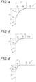
- An outer peripheral edge of each of the piston ring end faces 2a is provided with a chamfered edge 3. That is, the chamfered edge 3 is formed continuously to the piston ring end face 2a and an outer peripheral surface 1a of the piston ring 1.
- the outer peripheral edge of the piston ring end face 2a refers to an edge formed by the piston ring end face 2a and the outer peripheral surface 1a of the piston ring 1.
- the chamfered edge 3 is formed in a curved shape.
- the chamfered edge 3 includes a first arcuate surface 3a, a second arcuate surface 3b formed between the first arcuate surface 3a and the outer peripheral surface 1a of the piston ring 1, and a third arcuate surface 3c formed between the first arcuate surface 1a and the piston ring end face 2a.
- FIG. 2 is an enlarged view of a portion surrounded by broken lines in FIG. 1 .
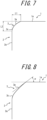
- perpendicular lines perpendicular to an annular profile line that corresponds to the outer peripheral surface 1a of the piston ring 1 are drawn at points 0.005 mm in a circumferential direction from (on left and right sides of) an intersection P1 of the first arcuate surface 3a and the outer peripheral surface 1a of the piston ring 1.
- Intersections of these perpendicular lines and the chamfered edge 3 are referred to as intersections P1a and P1b, and a partial region of the chamfered edge 3 between the intersection P1a and the intersection P1b is referred to as the second arcuate surface 3b.
- perpendicular lines perpendicular to a linear profile line that corresponds to the piston ring end face 2a of the piston ring 1 are drawn at points 0.005 mm in a radial direction from (on upper and lower sides of) an intersection P2 of the first arcuate surface 3a and the piston ring end face 2a. Intersections of these perpendicular lines and the chamfered edge 3 are referred to as intersections P2a and P2b, and a partial region of the chamfered edge 3 between the intersection P2a and the intersection P2b is referred to as the third arcuate surface 3c.
- a partial region of the chamfered edge 3 between the second arcuate surface 3b and the third arcuate surface 3c, i.e., the partial region of the chamfered edge 3 between the intersection P1b and the intersection P2b is referred to as the first arcuate surface 3a.
- the chamfered edge 3 is in a shape with a ratio of a radius R2 of the second arcuate surface 3b (see FIG. 2 ) to a radius R1 of the first arcuate surface 3a (see FIG. 2 ), of 0.1 to 0.8. Also, the chamfered edge 3 is in a shape with a ratio of a radius R3 of the third arcuate surface 3c (see FIG. 2 ) to the radius R1 of the first arcuate surface 3a, i.e., R3/R1 of preferably 0.50 or less, more preferably 0.050 to 0.500.
- the chamfered potion 3 is preferably in a shape having: a ratio of the radius R1 of the first arcuate surface 3a to a circumferential width L1 of the chamfered edge 3 (see FIG. 3 ) along a circumferential direction of the piston ring 1, i.e., R1/L1 of between 1.00 and 4.50; a ratio of the radius R1 of the first arcuate surface 3a to a radial width L2 of the chamfered edge 3 (see FIG.
- the chamfered edge 3 having the curved shape as described above may have, for example, a curved shape including the three arcuate surfaces 3a, 3b, and 3c as illustrated in FIG. 4 that is formed by subjecting the outer peripheral edge of the piston ring gap 2 to barrel finishing and brushing. Note that the formation of the chamfered edge 3 having the curved shape is not limited to these methods and may use other methods.
- the chamfered edge 3 having the curved shape formed by removing an edge enables a reduction in the circumferential width L1 of the chamfered edge 3 along the circumferential direction of the piston ring 1 and the radial width L2 along the radial direction of the piston ring 1, that is, enables a reduction in a chamfered amount of the chamfered edge, without making the chamfered edge 3 susceptible to the chipping.
- Sufficient size reduction of the chamfered edge 3 without leading to the chipping achieves sufficient size reduction of a flow passage of a blow-by gas in the piston ring gap 2, effectively restraining the blow-by gas from passing through the piston ring gap 2.
- the chamfered edge 3 preferably has a ratio of the circumferential width L1 to the radial width L2, i.e., L1/L2 of 0.6 to 2.0.
- the chamfered edge 3 has the ratio of the circumferential width L1 to the radial width L2 of 1.0; in other words, the circumferential width L1 and the radial width L2 are equal to each other.
- the chamfered edge 3 may have the circumferential width L1 greater than the radial width L2, thus preventing the chipping of the chamfered edge 3 in a more reliable manner.
- the chamfered edge 3 may include the first arcuate surface 3a and the third arcuate surface 3c omitting the second arcuate surface 3b, and have the circumferential width L1 smaller than the radial width L2.
- the chamfered edge 3 may include the first arcuate surface 3a and the third arcuate surface 3c omitting the second arcuate surface 3b, and have the circumferential width L1 and the radial width L2 equal to each other, or the circumferential width L1 greater than the radial width L2.
- the chamfered edge 3 may include the first arcuate surface 3a and the third arcuate surface 3c omitting the second arcuate surface 3b, and the first arcuate surface 3a may be shaped to be almost flat.
- the chamfered edge 3 may be defined by the circumferential width L1, the radial width L2, and the radial R3 of the third arcuate surface 3c.
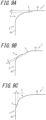
- the chamfered edge 3 is formed in such a manner that, at an intersection of the first arcuate surface 3a and the outer peripheral surface 1a of the piston ring 1, a tangential direction of the first arcuate surface 3a is inclined at an acute angle ⁇ relative to a tangential direction of the outer peripheral surface 1a of the piston ring 1. That is, the chamfered edge 3 includes an edge at the intersection of the first arcuate surface 3a and the outer peripheral surface 1a of the piston ring 1. In this way, the chamfered edge 3 may border the outer peripheral surface 1a of the piston ring 1 in a non-curved manner.
- the chamfered edge 3 may include a step 5.
- the step 5 may be a recess with a height h formed between the chamfered edge 3 and the outer peripheral surface 1a of the piston ring 1 as illustrated in FIG. 9A , or a protuberance with a height h formed between the chamfered edge 3 and the outer peripheral surface 1a of the piston ring 1 as illustrated in FIG. 9B .
- the step 5 may be a step with a height h formed between the chamfered edge 3 and the piston ring end face 2a as illustrated in FIG. 9C .
- the height h of the step 5 is preferably 5 ⁇ m or less.
- the chamfered edge 3 may have the step 5 with the height of 5 ⁇ m or less.
- a ratio of the circumferential width L1 of one of the chamfered edges 3 along the circumferential direction of the piston ring 1 (not illustrated and will be referred to as "L1a” hereinafter) to the circumferential width L1 of the other of the chamfered edges 3 along the circumferential direction of the piston ring 1 (not illustrated and will be referred to as "L1b” hereinafter), i.e., L1a/L1b is preferably 0.30 to 3.00.
- a ratio of the radial width L2 of one of the chamfered edges 3 along the radial direction of the piston ring 1 (not illustrated and will be referred to as "L2a” hereinafter) to the radial width L2 of the other of the chamfered edges 3 along the radial direction of the piston ring 1 (not illustrated and will be referred to as "L2b” hereinafter), i.e., L2a/L2b is preferably 0.30 to 3.00.
- a ratio of the radius R1 of the first arcuate surface 3a of the one of the chamfered edges 3 (not illustrated and will be referred to as "R1a” hereinafter) to the radius R1 of the first arcuate surface 3a of the other of the chamfered edges 3 (not illustrated and will be referred to as "R1b” hereinafter), i.e., R1a/R1b is preferably 0.18 to 5.50.
- a ratio of the radius R2 of the second arcuate surface 3b of the one of the chamfered edges 3 (not illustrated and will be referred to as "R2a” hereinafter) to the radius R2 of the second arcuate surface 3b of the other of the chamfered edges 3 (not illustrated and will be referred to as “R2b” hereinafter), i.e., R2a/R2b is preferably 0.18 to 5.50.
- a ratio of the radius R3 of the third arcuate surface 3c of the one of the chamfered edges 3 (not illustrated and will be referred to as "R3a” hereinafter) to the radius R3 of the third arcuate surface 3c of the other of the chamfered edges 3 (not illustrated and will be referred to as “R3b” hereinafter), i.e., R3a/R3b is preferably 0.18 to 5.50.
- the incidence of the chipping of the chamfered edge 3 may be reduced while the passage area of the piston ring gap 2 may be reduced, abating the amount of the blow-by gas.
- compression rings were prepared for examples 1 and 2, and another compression ring for a comparative example was prepared for comparison with the disclosure herein.
- the amounts of the blow-by gas (blow-by amounts, L/min) of these compression rings were measured and compared with one another.
- the chamfered edge was formed on each of a pair of piston ring end faces facing each other across the piston ring gap.
- the chamfered edge had a curved shape including the first arcuate surface, the second arcuate surface, and the third arcuate surface.
- the circumferential width and the radial width were each 0.055 to 0.075 mm, and a ratio of the circumferential width to the radial width was 0.733 to 1.750.
- a ratio of the circumferential width of one of the chamfered edges to the circumferential width of the other of the chamfered edges was 0.73 to 1.37, while a ratio of the radial width of one of the chamfered edges to the radial width of the other of the chamfered edges was 0.53 to 1.88.
- the radius of the first arcuate surface was 0.10 to 0.24 mm, the radius of the second arcuate surface was 0.04 to 0.16 mm, and the radius of the third arcuate surface was 0.015 to 0.050 mm.
- a ratio of the radius of the first arcuate surface of one of the chamfered edges to the radius of the first arcuate surface of the other of the chamfered edges was 0.41 to 2.40
- a ratio of the radius of the second arcuate surface of one of the chamfered edges to the radius of the second arcuate surface of the other of the chamfered edges was 0.25 to 4.00
- a ratio of the radius of the third arcuate surface of one of the chamfered edges to the radius of the third arcuate surface of the other of the chamfered edges was 0.30 to 3.34.
- a ratio of the radius of the first arcuate surface to the circumferential width of the chamfered edge was 1.333 to 4.364
- a ratio of the radius of the first arcuate surface to the radial width of the chamfered edge was 1.818 to 4.459.
- a ratio of the radius of the second arcuate surface to the radius of the first arcuate surface was 0.261 to 0.800
- a ratio of the radius of the third arcuate surface to the radius of the first arcuate surface was 0.084 to 0.302.
- the chamfered edge was formed on each of a pair of piston ring end faces facing each other across the piston ring gap.
- the chamfered edge had a curved shape including the first arcuate surface, the second arcuate surface, and the third arcuate surface, and had the chamfered amount smaller than that of the example 1. That is, the compression ring according to the example 2 had the circumferential width of 0.017 to 0.044 mm and the radial width of 0.022 to 0.045 mm. Also, the compression ring according to the example 2 had a ratio of the circumferential width to the radial width of 0.640 to 1.471.
- a ratio of the circumferential width of one of the chamfered edges to the circumferential width of the other of the chamfered edges was 0.38 to 2.60, while a ratio of the radial width of one of the chamfered edges to the radial width of the other of the chamfered edges was 0.48 to 2.05.
- a radius of the first arcuate surface was 0.030 to 0.157 mm, a radius of the second arcuate surface was 0.013 to 0.043 mm, and a radius of the third arcuate surface was 0.006 to 0.033 mm.
- a ratio of the radius of the first arcuate surface of one of the chamfered edges to the radius of the first arcuate surface of the other of the chamfered edges was 0.19 to 5.24
- a ratio of the radius of the second arcuate surface of one of the chamfered edges to the radius of the second arcuate surface of the other of the chamfered edges was 0.30 to 3.31
- a ratio of the radius of the third arcuate surface of one of the chamfered edges to the radius of the third arcuate surface of the other of the chamfered edges was 0.18 to 5.50.
- a ratio of the radius of the first arcuate surface to the circumferential width of the chamfered edge was 1.207 to 4.103
- a ratio of the radius of the first arcuate surface to the radial width of the chamfered edge was 1.028 to 4.489.
- a ratio of the radius of the second arcuate surface to the radius of the first arcuate surface was 0.154 to 0.781
- a ratio of the radius of the third arcuate surface to the radius of the first arcuate surface was 0.050 to 0.492.
- chamfered edges in a flat C-shape were formed.
- the chamfered edges had both the circumferential width and the radial width of 0.055 to 0.075 mm, and a ratio of the circumferential width to the radial width of 0.733 to 1.136.
- a ratio of the circumferential width of one of the chamfered edges to the circumferential width of the other of the chamfered edges was 0.73 to 1.37
- a ratio of the radial width of one of the chamfered edges to the radial width of the other of the chamfered edges was 0.53 to 1.88.
- the compression rings according to the examples 1 and 2 and the comparative example designed as described above were separately mounted on a top-ring groove of the piston ring in a turbo-charged petrol engine of a water-cooled 4-cycle (2.0 L displacement, 4 cylinders). Each of the compression rings being mounted had the piston ring gap of 0.25 mm. Under conditions of 6000 rpm and a full load (Wide Open Throttle, WOT), the amount of the blow-by gas when this engine was run for a predetermined time period was measured.
- WOT Wide Open Throttle
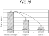
- the amount of the blow-by gas was measured by re-sucking the gas flowing into the crank chamber via the piston and measuring an amount of the re-sucked gas. Results of the measurements of the incidence of the chipping and the amount of the blow-by gas are illustrated in Table 1 and FIG. 10 .
- the columns of "a” are for those of one of the ring gap end surfaces (L1a, L2a, R1a, R2a, and R3a as mentioned above), while columns of "b” are for those of the other of the ring gap end surfaces (L1b, L2b, R1b, R2b, and R3b as mentioned above).
- the incidence of the chipping of the chamfered or chamfered edges was 0.35 % for the compression ring according to the example 1, 0.41 % for the compression ring according to the example 2, and 2.25 % for the compression ring according to the comparative example.
- the chamfered edge of the compression ring having the curved shape such as one according to the example 1 is capable of further reducing the incidence of the chipping of the chamfered edge than that of the chamfered edge of the compression ring having the flat C-shape such as one according to the comparative example.
- the chamfered edge is capable of further reducing the incidence of the chipping than that of the chamfered edge of the compression ring having the flat C-shape such as one according to the comparative example.
- the amount of the blow-by gas was 85 for the compression ring according to the example 1, and 72 for the compression ring according to the example 2.
- the chamfered edge of the compression ring having the curved shape such as one according to the example 1 is capable of reducing the amount of the blow-by gas 15% more than the chamfered edge of the compression ring having the flat C-shape such as one according to the comparative example.
- the chamfered edge is capable of reducing the amount of the blow-by gas 28% more than the chamfered edge of the compression ring having the flat C-shape such as one according to the comparative example.
- the chamfered edge having the curved shape enables the size reduction thereof without increasing the incidence of the chipping and the size reduction of the flow passage of the blow-by gas in the piston ring gap, effectively restraining the blow-by gas from passing through the piston ring gap.
- the chamfered edge 3 has the curved shape including the first, second, and third arcuate surfaces 3a, 3b, and 3c or first and third arcuate surfaces 3a and 3c.
- the chamfered edge 3 is not limited thereto and may have a curved shape including at least two arcuate surfaces overlapping one another.
Landscapes
- Engineering & Computer Science (AREA)
- General Engineering & Computer Science (AREA)
- Mechanical Engineering (AREA)
- Chemical & Material Sciences (AREA)
- Combustion & Propulsion (AREA)
- Pistons, Piston Rings, And Cylinders (AREA)
Applications Claiming Priority (2)
| Application Number | Priority Date | Filing Date | Title |
|---|---|---|---|
| JP2015137671A JP6695663B2 (ja) | 2015-07-09 | 2015-07-09 | 内燃機関用のピストンリング |
| PCT/JP2016/003124 WO2017006545A1 (ja) | 2015-07-09 | 2016-06-29 | 内燃機関用のピストンリング |
Publications (4)
| Publication Number | Publication Date |
|---|---|
| EP3321543A1 EP3321543A1 (en) | 2018-05-16 |
| EP3321543A4 EP3321543A4 (en) | 2019-03-06 |
| EP3321543B1 EP3321543B1 (en) | 2021-04-28 |
| EP3321543B2 true EP3321543B2 (en) | 2024-04-17 |
Family
ID=57685397
Family Applications (1)
| Application Number | Title | Priority Date | Filing Date |
|---|---|---|---|
| EP16821021.9A Active EP3321543B2 (en) | 2015-07-09 | 2016-06-29 | Internal combustion engine piston ring |
Country Status (5)
| Country | Link |
|---|---|
| US (1) | US10670146B2 (zh) |
| EP (1) | EP3321543B2 (zh) |
| JP (1) | JP6695663B2 (zh) |
| CN (1) | CN107835909B (zh) |
| WO (1) | WO2017006545A1 (zh) |
Families Citing this family (2)
| Publication number | Priority date | Publication date | Assignee | Title |
|---|---|---|---|---|
| USD909186S1 (en) * | 2019-01-08 | 2021-02-02 | Jian Wang | Quilt clip |
| JP7116718B2 (ja) * | 2019-12-11 | 2022-08-10 | 株式会社リケン | 圧力リング |
Citations (7)
| Publication number | Priority date | Publication date | Assignee | Title |
|---|---|---|---|---|
| GB633457A (en) † | 1947-10-09 | 1949-12-19 | Walter Perkins | Improvements in or relating to piston rings and the like packing rings |
| DE3441919C2 (zh) † | 1984-11-16 | 1987-11-19 | M.A.N.- B & W Diesel Gmbh, 8900 Augsburg, De | |
| JPH0624608Y2 (ja) † | 1988-04-20 | 1994-06-29 | 日本ピストンリング株式会社 | 組合せオイルリング |
| US5934680A (en) † | 1995-05-31 | 1999-08-10 | Ntn Corporation | Split resin seal ring with chamfered end connection structures |
| EP1767834A1 (en) † | 2004-07-05 | 2007-03-28 | Kabushiki Kaisha Riken | Piston ring for internal combustion engine |
| DE102009052587A1 (de) † | 2009-11-10 | 2011-05-12 | Federal-Mogul Burscheid Gmbh | Kolbenring |
| DE102015004814A1 (de) † | 2015-04-14 | 2016-10-20 | Daimler Ag | Verfahren zum Bearbeiten einer Kolbenbaugruppe und Kolbenbaugruppe |
Family Cites Families (33)
| Publication number | Priority date | Publication date | Assignee | Title |
|---|---|---|---|---|
| US2092413A (en) * | 1934-06-22 | 1937-09-07 | Westinghouse Air Brake Co | Piston ring joint |
| US2253739A (en) * | 1939-05-01 | 1941-08-26 | Trexler Jay | Piston and ring |
| US2404616A (en) * | 1943-07-14 | 1946-07-23 | Harry M Bramberry | Piston ring |
| US3455565A (en) * | 1964-07-29 | 1969-07-15 | Air Prod & Chem | Piston rings |
| US4533149A (en) | 1981-06-10 | 1985-08-06 | J. I. Case Company | Split seal ring with interlocking cut |
| JPS5867946A (ja) * | 1981-10-17 | 1983-04-22 | Honda Motor Co Ltd | 内燃機関のピストンリング |
| JPH0258165U (zh) | 1988-10-21 | 1990-04-26 | ||
| JPH0364654A (ja) * | 1989-07-31 | 1991-03-20 | Nissan Motor Co Ltd | 内燃機関用ピストン |
| US5469616A (en) * | 1990-11-15 | 1995-11-28 | Teikoku Piston Ring Co., Ltd. | Method of manufacturing a side rail of a combined oil ring |
| DE4202927C2 (de) * | 1992-02-01 | 2000-11-09 | Continental Teves Ag & Co Ohg | Scheibenbremse mit verbessertem Lüftverhalten |
| JPH0875007A (ja) | 1994-06-30 | 1996-03-19 | Ntn Corp | 合成樹脂製シールリング |
| CN1075594C (zh) * | 1995-01-26 | 2001-11-28 | 张明智 | 一种活塞组件 |
| JPH0989111A (ja) | 1995-09-29 | 1997-03-31 | Ntn Corp | 合成樹脂製シールリング |
| US5882012A (en) * | 1995-11-30 | 1999-03-16 | Ntn Corporation | Oil seal ring |
| JPH1089476A (ja) | 1996-09-19 | 1998-04-07 | Nippon Piston Ring Co Ltd | 組合せオイルリングのサイドレール |
| US5934685A (en) * | 1997-07-14 | 1999-08-10 | Danzer; Edward Leo | Step lock piston ring insert |
| DE10041954C1 (de) * | 2000-08-25 | 2002-02-14 | Mannesmann Sachs Ag | Kolbenring, insbesondere für einen Kolben eines Schwingungsdämpfers |
| CN2763548Y (zh) | 2005-02-02 | 2006-03-08 | 赵见喜 | 弧面环口式内燃机密封活塞环 |
| JP5101827B2 (ja) * | 2006-03-10 | 2012-12-19 | Ntn株式会社 | シールリング |
| CN101581259A (zh) | 2008-05-15 | 2009-11-18 | 高敦华 | 建立活塞环的机制密封单环活塞发动机 |
| JP2010031835A (ja) * | 2008-06-23 | 2010-02-12 | Nissan Motor Co Ltd | 内燃機関用オイルリング及びピストン |
| CN202039965U (zh) | 2010-10-26 | 2011-11-16 | 中外合资安庆帝伯格茨活塞环有限公司 | 一种降低环槽磨损的活塞环 |
| WO2013031548A1 (ja) | 2011-08-29 | 2013-03-07 | 旭硝子株式会社 | ガラス板 |
| USD668941S1 (en) * | 2012-05-10 | 2012-10-16 | Ellen Taurins | Circle ring |
| DE102013206399A1 (de) * | 2013-04-11 | 2014-10-16 | Federal-Mogul Friedberg Gmbh | Kolbenring mit periodisch variierender Laufflächenbreite |
| US10253882B2 (en) * | 2013-12-30 | 2019-04-09 | Mahle International Gmbh | Oil control ring assembly |
| BR102014004402B1 (pt) * | 2014-02-25 | 2022-08-09 | Mahle Metal Leve S/A | Anel de pistão e seu processo de fabricação |
| EP3163129B1 (en) * | 2014-06-27 | 2020-10-14 | Kabushiki Kaisha Riken | Piston ring |
| JP6122901B2 (ja) * | 2014-07-31 | 2017-04-26 | 日本ピストンリング株式会社 | 組合せオイルリング |
| US9334959B2 (en) * | 2014-09-04 | 2016-05-10 | Matthew Hartford | Radially notched piston rings |
| JP6222023B2 (ja) * | 2014-09-12 | 2017-11-01 | マツダ株式会社 | オイルリング |
| MX356143B (es) * | 2014-09-12 | 2018-05-16 | Tpr Co Ltd | Anillo de aceite de combinación. |
| JP6533670B2 (ja) * | 2015-03-12 | 2019-06-19 | 株式会社リケン | サイドレール |
-
2015
- 2015-07-09 JP JP2015137671A patent/JP6695663B2/ja active Active
-
2016
- 2016-06-29 WO PCT/JP2016/003124 patent/WO2017006545A1/ja active Application Filing
- 2016-06-29 US US15/740,064 patent/US10670146B2/en active Active
- 2016-06-29 EP EP16821021.9A patent/EP3321543B2/en active Active
- 2016-06-29 CN CN201680039829.XA patent/CN107835909B/zh active Active
Patent Citations (7)
| Publication number | Priority date | Publication date | Assignee | Title |
|---|---|---|---|---|
| GB633457A (en) † | 1947-10-09 | 1949-12-19 | Walter Perkins | Improvements in or relating to piston rings and the like packing rings |
| DE3441919C2 (zh) † | 1984-11-16 | 1987-11-19 | M.A.N.- B & W Diesel Gmbh, 8900 Augsburg, De | |
| JPH0624608Y2 (ja) † | 1988-04-20 | 1994-06-29 | 日本ピストンリング株式会社 | 組合せオイルリング |
| US5934680A (en) † | 1995-05-31 | 1999-08-10 | Ntn Corporation | Split resin seal ring with chamfered end connection structures |
| EP1767834A1 (en) † | 2004-07-05 | 2007-03-28 | Kabushiki Kaisha Riken | Piston ring for internal combustion engine |
| DE102009052587A1 (de) † | 2009-11-10 | 2011-05-12 | Federal-Mogul Burscheid Gmbh | Kolbenring |
| DE102015004814A1 (de) † | 2015-04-14 | 2016-10-20 | Daimler Ag | Verfahren zum Bearbeiten einer Kolbenbaugruppe und Kolbenbaugruppe |
Also Published As
| Publication number | Publication date |
|---|---|
| CN107835909B (zh) | 2020-06-19 |
| EP3321543A4 (en) | 2019-03-06 |
| US10670146B2 (en) | 2020-06-02 |
| US20180187780A1 (en) | 2018-07-05 |
| EP3321543B1 (en) | 2021-04-28 |
| JP6695663B2 (ja) | 2020-05-20 |
| CN107835909A (zh) | 2018-03-23 |
| JP2017020553A (ja) | 2017-01-26 |
| WO2017006545A1 (ja) | 2017-01-12 |
| EP3321543A1 (en) | 2018-05-16 |
Similar Documents
| Publication | Publication Date | Title |
|---|---|---|
| US8157268B2 (en) | Piston for internal combustion engines | |
| US9482153B2 (en) | Oil retention in the bore/piston interfaces of ported cylinders in opposed-piston engines | |
| EP2045488B1 (en) | Piston ring of reciprocating engine | |
| US20070272078A1 (en) | Piston Device for Internal Combustion Engine | |
| EP3279524B1 (en) | Side rail | |
| EP3270012A1 (en) | Side rail | |
| US7267602B2 (en) | Seal assembly manufacturing methods | |
| EP3176474B1 (en) | Combination oil ring | |
| EP2812553B1 (en) | Piston with enhanced cooling gallery | |
| EP3321543B2 (en) | Internal combustion engine piston ring | |
| KR102624586B1 (ko) | 실린더 라이너 및 실린더 보어 | |
| KR102002662B1 (ko) | 내연 엔진용 피스톤 링 | |
| US9163725B2 (en) | Oil control ring with ferrous body less than 2.0 millimeters high for internal combustion engines | |
| US10359112B2 (en) | Piston ring set for internal combustion engine and system and method thereof | |
| EP2905454A1 (en) | Cylinder liner with deposit wiping face | |
| EP3677764B1 (en) | Side rail | |
| US20240110625A1 (en) | Compression Ring | |
| JP2013148026A (ja) | シリンダライナ | |
| JP2023050681A (ja) | ピストンリングの組合せ、及び内燃機関 | |
| JPH04159441A (ja) | エンジン | |
| JPH0478375A (ja) | ピストン用オイルリング | |
| CN217682005U (zh) | 气缸 | |
| US20210062916A1 (en) | Piston assembly for an internal combustion engine of a motor vehicle | |
| JPS6392867A (ja) | 第二圧力リング |
Legal Events
| Date | Code | Title | Description |
|---|---|---|---|
| STAA | Information on the status of an ep patent application or granted ep patent |
Free format text: STATUS: THE INTERNATIONAL PUBLICATION HAS BEEN MADE |
|
| PUAI | Public reference made under article 153(3) epc to a published international application that has entered the european phase |
Free format text: ORIGINAL CODE: 0009012 |
|
| STAA | Information on the status of an ep patent application or granted ep patent |
Free format text: STATUS: REQUEST FOR EXAMINATION WAS MADE |
|
| 17P | Request for examination filed |
Effective date: 20180103 |
|
| AK | Designated contracting states |
Kind code of ref document: A1 Designated state(s): AL AT BE BG CH CY CZ DE DK EE ES FI FR GB GR HR HU IE IS IT LI LT LU LV MC MK MT NL NO PL PT RO RS SE SI SK SM TR |
|
| AX | Request for extension of the european patent |
Extension state: BA ME |
|
| DAV | Request for validation of the european patent (deleted) | ||
| DAX | Request for extension of the european patent (deleted) | ||
| A4 | Supplementary search report drawn up and despatched |
Effective date: 20190131 |
|
| RIC1 | Information provided on ipc code assigned before grant |
Ipc: F16J 9/20 20060101AFI20190125BHEP Ipc: F02F 5/00 20060101ALI20190125BHEP Ipc: F16J 9/14 20060101ALI20190125BHEP |
|
| GRAP | Despatch of communication of intention to grant a patent |
Free format text: ORIGINAL CODE: EPIDOSNIGR1 |
|
| STAA | Information on the status of an ep patent application or granted ep patent |
Free format text: STATUS: GRANT OF PATENT IS INTENDED |
|
| INTG | Intention to grant announced |
Effective date: 20201204 |
|
| GRAS | Grant fee paid |
Free format text: ORIGINAL CODE: EPIDOSNIGR3 |
|
| GRAA | (expected) grant |
Free format text: ORIGINAL CODE: 0009210 |
|
| STAA | Information on the status of an ep patent application or granted ep patent |
Free format text: STATUS: THE PATENT HAS BEEN GRANTED |
|
| AK | Designated contracting states |
Kind code of ref document: B1 Designated state(s): AL AT BE BG CH CY CZ DE DK EE ES FI FR GB GR HR HU IE IS IT LI LT LU LV MC MK MT NL NO PL PT RO RS SE SI SK SM TR |
|
| REG | Reference to a national code |
Ref country code: GB Ref legal event code: FG4D |
|
| REG | Reference to a national code |
Ref country code: CH Ref legal event code: EP |
|
| REG | Reference to a national code |
Ref country code: AT Ref legal event code: REF Ref document number: 1387426 Country of ref document: AT Kind code of ref document: T Effective date: 20210515 |
|
| REG | Reference to a national code |
Ref country code: DE Ref legal event code: R096 Ref document number: 602016057032 Country of ref document: DE |
|
| REG | Reference to a national code |
Ref country code: IE Ref legal event code: FG4D |
|
| REG | Reference to a national code |
Ref country code: LT Ref legal event code: MG9D |
|
| REG | Reference to a national code |
Ref country code: AT Ref legal event code: MK05 Ref document number: 1387426 Country of ref document: AT Kind code of ref document: T Effective date: 20210428 |
|
| PG25 | Lapsed in a contracting state [announced via postgrant information from national office to epo] |
Ref country code: HR Free format text: LAPSE BECAUSE OF FAILURE TO SUBMIT A TRANSLATION OF THE DESCRIPTION OR TO PAY THE FEE WITHIN THE PRESCRIBED TIME-LIMIT Effective date: 20210428 Ref country code: BG Free format text: LAPSE BECAUSE OF FAILURE TO SUBMIT A TRANSLATION OF THE DESCRIPTION OR TO PAY THE FEE WITHIN THE PRESCRIBED TIME-LIMIT Effective date: 20210728 Ref country code: AT Free format text: LAPSE BECAUSE OF FAILURE TO SUBMIT A TRANSLATION OF THE DESCRIPTION OR TO PAY THE FEE WITHIN THE PRESCRIBED TIME-LIMIT Effective date: 20210428 Ref country code: NL Free format text: LAPSE BECAUSE OF FAILURE TO SUBMIT A TRANSLATION OF THE DESCRIPTION OR TO PAY THE FEE WITHIN THE PRESCRIBED TIME-LIMIT Effective date: 20210428 Ref country code: LT Free format text: LAPSE BECAUSE OF FAILURE TO SUBMIT A TRANSLATION OF THE DESCRIPTION OR TO PAY THE FEE WITHIN THE PRESCRIBED TIME-LIMIT Effective date: 20210428 Ref country code: FI Free format text: LAPSE BECAUSE OF FAILURE TO SUBMIT A TRANSLATION OF THE DESCRIPTION OR TO PAY THE FEE WITHIN THE PRESCRIBED TIME-LIMIT Effective date: 20210428 |
|
| PG25 | Lapsed in a contracting state [announced via postgrant information from national office to epo] |
Ref country code: LV Free format text: LAPSE BECAUSE OF FAILURE TO SUBMIT A TRANSLATION OF THE DESCRIPTION OR TO PAY THE FEE WITHIN THE PRESCRIBED TIME-LIMIT Effective date: 20210428 Ref country code: IS Free format text: LAPSE BECAUSE OF FAILURE TO SUBMIT A TRANSLATION OF THE DESCRIPTION OR TO PAY THE FEE WITHIN THE PRESCRIBED TIME-LIMIT Effective date: 20210828 Ref country code: GR Free format text: LAPSE BECAUSE OF FAILURE TO SUBMIT A TRANSLATION OF THE DESCRIPTION OR TO PAY THE FEE WITHIN THE PRESCRIBED TIME-LIMIT Effective date: 20210729 Ref country code: PL Free format text: LAPSE BECAUSE OF FAILURE TO SUBMIT A TRANSLATION OF THE DESCRIPTION OR TO PAY THE FEE WITHIN THE PRESCRIBED TIME-LIMIT Effective date: 20210428 Ref country code: NO Free format text: LAPSE BECAUSE OF FAILURE TO SUBMIT A TRANSLATION OF THE DESCRIPTION OR TO PAY THE FEE WITHIN THE PRESCRIBED TIME-LIMIT Effective date: 20210728 Ref country code: PT Free format text: LAPSE BECAUSE OF FAILURE TO SUBMIT A TRANSLATION OF THE DESCRIPTION OR TO PAY THE FEE WITHIN THE PRESCRIBED TIME-LIMIT Effective date: 20210830 Ref country code: SE Free format text: LAPSE BECAUSE OF FAILURE TO SUBMIT A TRANSLATION OF THE DESCRIPTION OR TO PAY THE FEE WITHIN THE PRESCRIBED TIME-LIMIT Effective date: 20210428 Ref country code: RS Free format text: LAPSE BECAUSE OF FAILURE TO SUBMIT A TRANSLATION OF THE DESCRIPTION OR TO PAY THE FEE WITHIN THE PRESCRIBED TIME-LIMIT Effective date: 20210428 |
|
| REG | Reference to a national code |
Ref country code: NL Ref legal event code: MP Effective date: 20210428 |
|
| REG | Reference to a national code |
Ref country code: DE Ref legal event code: R026 Ref document number: 602016057032 Country of ref document: DE |
|
| PG25 | Lapsed in a contracting state [announced via postgrant information from national office to epo] |
Ref country code: SK Free format text: LAPSE BECAUSE OF FAILURE TO SUBMIT A TRANSLATION OF THE DESCRIPTION OR TO PAY THE FEE WITHIN THE PRESCRIBED TIME-LIMIT Effective date: 20210428 Ref country code: SM Free format text: LAPSE BECAUSE OF FAILURE TO SUBMIT A TRANSLATION OF THE DESCRIPTION OR TO PAY THE FEE WITHIN THE PRESCRIBED TIME-LIMIT Effective date: 20210428 Ref country code: RO Free format text: LAPSE BECAUSE OF FAILURE TO SUBMIT A TRANSLATION OF THE DESCRIPTION OR TO PAY THE FEE WITHIN THE PRESCRIBED TIME-LIMIT Effective date: 20210428 Ref country code: ES Free format text: LAPSE BECAUSE OF FAILURE TO SUBMIT A TRANSLATION OF THE DESCRIPTION OR TO PAY THE FEE WITHIN THE PRESCRIBED TIME-LIMIT Effective date: 20210428 Ref country code: EE Free format text: LAPSE BECAUSE OF FAILURE TO SUBMIT A TRANSLATION OF THE DESCRIPTION OR TO PAY THE FEE WITHIN THE PRESCRIBED TIME-LIMIT Effective date: 20210428 Ref country code: DK Free format text: LAPSE BECAUSE OF FAILURE TO SUBMIT A TRANSLATION OF THE DESCRIPTION OR TO PAY THE FEE WITHIN THE PRESCRIBED TIME-LIMIT Effective date: 20210428 Ref country code: CZ Free format text: LAPSE BECAUSE OF FAILURE TO SUBMIT A TRANSLATION OF THE DESCRIPTION OR TO PAY THE FEE WITHIN THE PRESCRIBED TIME-LIMIT Effective date: 20210428 Ref country code: MC Free format text: LAPSE BECAUSE OF FAILURE TO SUBMIT A TRANSLATION OF THE DESCRIPTION OR TO PAY THE FEE WITHIN THE PRESCRIBED TIME-LIMIT Effective date: 20210428 |
|
| REG | Reference to a national code |
Ref country code: CH Ref legal event code: PL |
|
| PLBI | Opposition filed |
Free format text: ORIGINAL CODE: 0009260 |
|
| 26 | Opposition filed |
Opponent name: MAHLE INTERNATIONAL GMBH Effective date: 20220127 |
|
| REG | Reference to a national code |
Ref country code: BE Ref legal event code: MM Effective date: 20210630 |
|
| GBPC | Gb: european patent ceased through non-payment of renewal fee |
Effective date: 20210728 |
|
| PG25 | Lapsed in a contracting state [announced via postgrant information from national office to epo] |
Ref country code: LU Free format text: LAPSE BECAUSE OF NON-PAYMENT OF DUE FEES Effective date: 20210629 |
|
| PLAX | Notice of opposition and request to file observation + time limit sent |
Free format text: ORIGINAL CODE: EPIDOSNOBS2 |
|
| PG25 | Lapsed in a contracting state [announced via postgrant information from national office to epo] |
Ref country code: LI Free format text: LAPSE BECAUSE OF NON-PAYMENT OF DUE FEES Effective date: 20210630 Ref country code: IE Free format text: LAPSE BECAUSE OF NON-PAYMENT OF DUE FEES Effective date: 20210629 Ref country code: GB Free format text: LAPSE BECAUSE OF NON-PAYMENT OF DUE FEES Effective date: 20210728 Ref country code: CH Free format text: LAPSE BECAUSE OF NON-PAYMENT OF DUE FEES Effective date: 20210630 |
|
| PG25 | Lapsed in a contracting state [announced via postgrant information from national office to epo] |
Ref country code: IS Free format text: LAPSE BECAUSE OF FAILURE TO SUBMIT A TRANSLATION OF THE DESCRIPTION OR TO PAY THE FEE WITHIN THE PRESCRIBED TIME-LIMIT Effective date: 20210828 Ref country code: AL Free format text: LAPSE BECAUSE OF FAILURE TO SUBMIT A TRANSLATION OF THE DESCRIPTION OR TO PAY THE FEE WITHIN THE PRESCRIBED TIME-LIMIT Effective date: 20210428 Ref country code: FR Free format text: LAPSE BECAUSE OF NON-PAYMENT OF DUE FEES Effective date: 20210630 |
|
| PG25 | Lapsed in a contracting state [announced via postgrant information from national office to epo] |
Ref country code: IT Free format text: LAPSE BECAUSE OF FAILURE TO SUBMIT A TRANSLATION OF THE DESCRIPTION OR TO PAY THE FEE WITHIN THE PRESCRIBED TIME-LIMIT Effective date: 20210428 Ref country code: BE Free format text: LAPSE BECAUSE OF NON-PAYMENT OF DUE FEES Effective date: 20210630 |
|
| PLBB | Reply of patent proprietor to notice(s) of opposition received |
Free format text: ORIGINAL CODE: EPIDOSNOBS3 |
|
| P01 | Opt-out of the competence of the unified patent court (upc) registered |
Effective date: 20230517 |
|
| PG25 | Lapsed in a contracting state [announced via postgrant information from national office to epo] |
Ref country code: CY Free format text: LAPSE BECAUSE OF FAILURE TO SUBMIT A TRANSLATION OF THE DESCRIPTION OR TO PAY THE FEE WITHIN THE PRESCRIBED TIME-LIMIT Effective date: 20210428 |
|
| PG25 | Lapsed in a contracting state [announced via postgrant information from national office to epo] |
Ref country code: HU Free format text: LAPSE BECAUSE OF FAILURE TO SUBMIT A TRANSLATION OF THE DESCRIPTION OR TO PAY THE FEE WITHIN THE PRESCRIBED TIME-LIMIT; INVALID AB INITIO Effective date: 20160629 |
|
| PUAH | Patent maintained in amended form |
Free format text: ORIGINAL CODE: 0009272 |
|
| STAA | Information on the status of an ep patent application or granted ep patent |
Free format text: STATUS: PATENT MAINTAINED AS AMENDED |
|
| 27A | Patent maintained in amended form |
Effective date: 20240417 |
|
| AK | Designated contracting states |
Kind code of ref document: B2 Designated state(s): AL AT BE BG CH CY CZ DE DK EE ES FI FR GB GR HR HU IE IS IT LI LT LU LV MC MK MT NL NO PL PT RO RS SE SI SK SM TR |
|
| REG | Reference to a national code |
Ref country code: DE Ref legal event code: R102 Ref document number: 602016057032 Country of ref document: DE |
|
| PG25 | Lapsed in a contracting state [announced via postgrant information from national office to epo] |
Ref country code: MK Free format text: LAPSE BECAUSE OF FAILURE TO SUBMIT A TRANSLATION OF THE DESCRIPTION OR TO PAY THE FEE WITHIN THE PRESCRIBED TIME-LIMIT Effective date: 20210428 |
|
| PGFP | Annual fee paid to national office [announced via postgrant information from national office to epo] |
Ref country code: DE Payment date: 20240507 Year of fee payment: 9 |