EP3319496B1 - Küchengerät - Google Patents
Küchengerät Download PDFInfo
- Publication number
- EP3319496B1 EP3319496B1 EP16820557.3A EP16820557A EP3319496B1 EP 3319496 B1 EP3319496 B1 EP 3319496B1 EP 16820557 A EP16820557 A EP 16820557A EP 3319496 B1 EP3319496 B1 EP 3319496B1
- Authority
- EP
- European Patent Office
- Prior art keywords
- temperature
- attachment
- mixer
- chocolate
- kitchen appliance
- Prior art date
- Legal status (The legal status is an assumption and is not a legal conclusion. Google has not performed a legal analysis and makes no representation as to the accuracy of the status listed.)
- Active
Links
- 238000010438 heat treatment Methods 0.000 claims description 24
- 238000012545 processing Methods 0.000 claims description 10
- 239000002184 metal Substances 0.000 claims description 4
- 244000299461 Theobroma cacao Species 0.000 description 41
- 235000019219 chocolate Nutrition 0.000 description 39
- 238000002156 mixing Methods 0.000 description 38
- 235000013305 food Nutrition 0.000 description 23
- 238000002360 preparation method Methods 0.000 description 22
- 239000004615 ingredient Substances 0.000 description 15
- 235000013361 beverage Nutrition 0.000 description 14
- 238000001816 cooling Methods 0.000 description 12
- 235000015243 ice cream Nutrition 0.000 description 9
- 239000000203 mixture Substances 0.000 description 9
- 235000021185 dessert Nutrition 0.000 description 7
- 238000009529 body temperature measurement Methods 0.000 description 5
- 238000000034 method Methods 0.000 description 5
- 238000013019 agitation Methods 0.000 description 4
- 238000005259 measurement Methods 0.000 description 4
- 238000005496 tempering Methods 0.000 description 4
- 238000012546 transfer Methods 0.000 description 4
- 230000001276 controlling effect Effects 0.000 description 3
- 238000010411 cooking Methods 0.000 description 3
- 235000013601 eggs Nutrition 0.000 description 3
- 230000005291 magnetic effect Effects 0.000 description 3
- 238000002844 melting Methods 0.000 description 3
- 230000008018 melting Effects 0.000 description 3
- 230000001105 regulatory effect Effects 0.000 description 3
- 239000000523 sample Substances 0.000 description 3
- 244000291564 Allium cepa Species 0.000 description 2
- 235000002732 Allium cepa var. cepa Nutrition 0.000 description 2
- 241000195940 Bryophyta Species 0.000 description 2
- 235000009470 Theobroma cacao Nutrition 0.000 description 2
- 238000005452 bending Methods 0.000 description 2
- 235000008429 bread Nutrition 0.000 description 2
- 238000002425 crystallisation Methods 0.000 description 2
- 230000008025 crystallization Effects 0.000 description 2
- 235000011850 desserts Nutrition 0.000 description 2
- 238000010586 diagram Methods 0.000 description 2
- 235000019197 fats Nutrition 0.000 description 2
- 230000006698 induction Effects 0.000 description 2
- 238000004898 kneading Methods 0.000 description 2
- 239000000463 material Substances 0.000 description 2
- 235000011929 mousse Nutrition 0.000 description 2
- NJPPVKZQTLUDBO-UHFFFAOYSA-N novaluron Chemical compound C1=C(Cl)C(OC(F)(F)C(OC(F)(F)F)F)=CC=C1NC(=O)NC(=O)C1=C(F)C=CC=C1F NJPPVKZQTLUDBO-UHFFFAOYSA-N 0.000 description 2
- 238000004804 winding Methods 0.000 description 2
- 229920001634 Copolyester Polymers 0.000 description 1
- 240000006766 Cornus mas Species 0.000 description 1
- 235000003363 Cornus mas Nutrition 0.000 description 1
- 238000004873 anchoring Methods 0.000 description 1
- 238000010009 beating Methods 0.000 description 1
- 239000000872 buffer Substances 0.000 description 1
- 230000003139 buffering effect Effects 0.000 description 1
- 229940110456 cocoa butter Drugs 0.000 description 1
- 235000019868 cocoa butter Nutrition 0.000 description 1
- 238000004891 communication Methods 0.000 description 1
- 238000005520 cutting process Methods 0.000 description 1
- 230000001419 dependent effect Effects 0.000 description 1
- 230000001627 detrimental effect Effects 0.000 description 1
- 235000013399 edible fruits Nutrition 0.000 description 1
- 230000000694 effects Effects 0.000 description 1
- 230000005294 ferromagnetic effect Effects 0.000 description 1
- 238000000227 grinding Methods 0.000 description 1
- 238000010348 incorporation Methods 0.000 description 1
- 235000015250 liver sausages Nutrition 0.000 description 1
- 238000011068 loading method Methods 0.000 description 1
- 238000003801 milling Methods 0.000 description 1
- 238000013021 overheating Methods 0.000 description 1
- 229920003023 plastic Polymers 0.000 description 1
- 239000004033 plastic Substances 0.000 description 1
- 229920001296 polysiloxane Polymers 0.000 description 1
- 229920002631 room-temperature vulcanizate silicone Polymers 0.000 description 1
- 239000007787 solid Substances 0.000 description 1
- 235000021055 solid food Nutrition 0.000 description 1
- 229910001220 stainless steel Inorganic materials 0.000 description 1
- 239000010935 stainless steel Substances 0.000 description 1
- 238000003756 stirring Methods 0.000 description 1
- 239000006188 syrup Substances 0.000 description 1
- 235000020357 syrup Nutrition 0.000 description 1
- 229920002725 thermoplastic elastomer Polymers 0.000 description 1
- 230000007704 transition Effects 0.000 description 1
- 230000000007 visual effect Effects 0.000 description 1
- 235000013618 yogurt Nutrition 0.000 description 1
Images


Classifications
-
- A—HUMAN NECESSITIES
- A47—FURNITURE; DOMESTIC ARTICLES OR APPLIANCES; COFFEE MILLS; SPICE MILLS; SUCTION CLEANERS IN GENERAL
- A47J—KITCHEN EQUIPMENT; COFFEE MILLS; SPICE MILLS; APPARATUS FOR MAKING BEVERAGES
- A47J43/00—Implements for preparing or holding food, not provided for in other groups of this subclass
- A47J43/04—Machines for domestic use not covered elsewhere, e.g. for grinding, mixing, stirring, kneading, emulsifying, whipping or beating foodstuffs, e.g. power-driven
- A47J43/07—Parts or details, e.g. mixing tools, whipping tools
- A47J43/0705—Parts or details, e.g. mixing tools, whipping tools for machines with tools driven from the upper side
- A47J43/0711—Parts or details, e.g. mixing tools, whipping tools for machines with tools driven from the upper side mixing, whipping or cutting tools
-
- A—HUMAN NECESSITIES
- A47—FURNITURE; DOMESTIC ARTICLES OR APPLIANCES; COFFEE MILLS; SPICE MILLS; SUCTION CLEANERS IN GENERAL
- A47J—KITCHEN EQUIPMENT; COFFEE MILLS; SPICE MILLS; APPARATUS FOR MAKING BEVERAGES
- A47J43/00—Implements for preparing or holding food, not provided for in other groups of this subclass
- A47J43/04—Machines for domestic use not covered elsewhere, e.g. for grinding, mixing, stirring, kneading, emulsifying, whipping or beating foodstuffs, e.g. power-driven
- A47J43/06—Machines for domestic use not covered elsewhere, e.g. for grinding, mixing, stirring, kneading, emulsifying, whipping or beating foodstuffs, e.g. power-driven with a plurality of interchangeable working units, e.g. with a single driving-unit
-
- A—HUMAN NECESSITIES
- A47—FURNITURE; DOMESTIC ARTICLES OR APPLIANCES; COFFEE MILLS; SPICE MILLS; SUCTION CLEANERS IN GENERAL
- A47J—KITCHEN EQUIPMENT; COFFEE MILLS; SPICE MILLS; APPARATUS FOR MAKING BEVERAGES
- A47J43/00—Implements for preparing or holding food, not provided for in other groups of this subclass
- A47J43/04—Machines for domestic use not covered elsewhere, e.g. for grinding, mixing, stirring, kneading, emulsifying, whipping or beating foodstuffs, e.g. power-driven
- A47J43/07—Parts or details, e.g. mixing tools, whipping tools
-
- A—HUMAN NECESSITIES
- A47—FURNITURE; DOMESTIC ARTICLES OR APPLIANCES; COFFEE MILLS; SPICE MILLS; SUCTION CLEANERS IN GENERAL
- A47J—KITCHEN EQUIPMENT; COFFEE MILLS; SPICE MILLS; APPARATUS FOR MAKING BEVERAGES
- A47J43/00—Implements for preparing or holding food, not provided for in other groups of this subclass
- A47J43/04—Machines for domestic use not covered elsewhere, e.g. for grinding, mixing, stirring, kneading, emulsifying, whipping or beating foodstuffs, e.g. power-driven
- A47J43/044—Machines for domestic use not covered elsewhere, e.g. for grinding, mixing, stirring, kneading, emulsifying, whipping or beating foodstuffs, e.g. power-driven with tools driven from the top side
- A47J2043/04454—Apparatus of counter top type
-
- A—HUMAN NECESSITIES
- A47—FURNITURE; DOMESTIC ARTICLES OR APPLIANCES; COFFEE MILLS; SPICE MILLS; SUCTION CLEANERS IN GENERAL
- A47J—KITCHEN EQUIPMENT; COFFEE MILLS; SPICE MILLS; APPARATUS FOR MAKING BEVERAGES
- A47J2202/00—Devices having temperature indicating means
Definitions
- the present invention relates generally to kitchen appliances used in the preparation of food and beverage.
- Some kitchen appliances such as stand mixers, have the ability to heat its content being mixed, while other kitchen appliances, such as ice cream makers, have the ability to cool the ingredients. In order to fully control the heating or cooling process, accurate temperature sensing of the content is desirable.
- a beverage container assembly for use with a blender comprising a beverage container having an open top portion and a closed bottom portion.
- a first removable cover is for selectively covering the top portion of the beverage container.
- a kitchen appliance comprising a motor and a controller for controlling the speed of the motor.
- the kitchen appliance further comprises a base, a head comprising an attachment interface adapted to receive a kitchen appliance attachment, and a stand for supporting the head on the base.
- the head is pivotable with respect to the stand between a raised and a lowered position.
- a bench mixer having a combined whisk and scraper attachment.
- the mixer has a processor configured to access data indicative of a respective power limit to be applied to a motor for each of a plurality of user selectable speed settings and monitors motor speed to compare against a user selected speed setting.
- a food processing apparatus having a blade assembly that can be driven at both stirring and processing speeds.
- the blade assembly rotates in a vessel that may be heated
- the apparatus includes stored sequences for operating a processing tool.
- the stored sequences may address various challenging aspects of blending solid foods and/or ice.
- preparation and “processing”, and variations thereof, as used herein refer to all aspects of food and/or beverage preparation including, but not limited to, grinding, cutting, kneading, milling, mixing, and cooking.
- a kitchen appliance as defined in claim 1.
- the one or more sensors being used to sense that property of the food or beverage to be in close proximity to the food or beverage being prepared.
- the sensors should be in contact with the food or beverage during the preparation thereof.
- the temperature probe would typically interfere with the beater's motion.
- One solution proposed herein is incorporating sensors into the bowl within which the content is being mixed or processed. However, such bowls are removable, making connection and powering of such sensors difficult and susceptible to damage under high loading of the bowl.
- Another solution proposed herein is incorporating sensors into the attachments used for processing the content. However, those attachments are not only removable, but also rotate at high speeds. In addition, the rotation of the attachments is often accompanied by complex planetary mixing actions.
- Fig. 1A shows a side view of a stand mixer 100 according to the current disclosure.
- Fig. 1B shows a sectional view of the stand mixer 100 shown in Fig. 1A .
- the stand mixer 100 has a pedestal 120 having a base 121 for supporting a mixing bowl 110, and an upright portion 122 for pivotally supporting a head assembly 130 of the stand mixer 100.
- the head assembly 130 houses an electric motor and drive system 132.
- the head assembly 130 also has a rotating head 133 and a drive shaft 131 extending therefrom, overhead of the bowl 110.
- the attachment shown in Figs. 1A and 1B is a beater 140. When attached, the attachment is suspended into the bowl 110 from the drive shaft 131.
- the stand mixer 100 is a planetary mixer which operates to impart a planetary mixing action to the attachment 140.
- the stand mixer 100 can be a non-planetary mixer and impart a different (non-planetary) type of mixing action to the attachment 140, for example a spiral mixing action or the like.
- the drive shaft 131 and rotating head 133 when driven by the electric motor and drive system 132, imparts a planetary mixing action to the attachment in the example described in relation to Fig. 1A .
- Each attachment has special features, allowing a wide variety of tasks to be performed by the stand mixer 100, including whisking, beating, dough kneading, etc.
- the base 121 includes a heating means (not shown) for heating the bowl 110, which in turn transfers that heat to the content 150 of the bowl 110 whilst that content is being subjected to the planetary mixing action.
- the heating means uses induction heating to heat the bowl 110 containing a ferromagnetic metal, such as magnetic stainless steel. More particularly, coils (not shown) are incorporated into the base 121, and when energized, those coils induce eddy currents in the base of the bowl 110, causing the bowl 110 to heat. Other methods of heating the bowl may also be used.
- the heating means referred to herein is able to heat the bowl 110 to any temperature from ambient up to 180 degrees Celsius.
- the stand mixer 100 further includes one or more temperature sensors 112, such as negative temperature coefficient (NTC) sensors, for sensing the temperature of the content 150 of the bowl 110.
- NTC negative temperature coefficient
- the temperature sensors 112 are incorporated within the attachment.
- the attachment may be made of a plastics material, allowing the temperature sensors 112 to be moulded within the attachment.
- the attachment may also be diecast in the manner described below with reference to Fig. 3A . In use the temperature sensors 112 are not only in contact with the content 150, but also move through the content 150 following the planetary mixing action, thereby sensing the temperature throughout the content 150 to permit accurate temperature measurements to be made.
- the upright portion 122 of the pedestal 120 further includes a user interface 123 for receiving user settings, including mixing speed, temperature and mixing and/or heating times.
- a microprocessor based controller (not shown) is also provided for controlling the operation of the stand mixer 100. More particularly, the controller uses user settings received through the user interface 123 and input from sensors, including the temperature sensors 112, to control the electric motor (i.e. motor speed and operation period) and the heating means (i.e. temperature and duration of heating).
- Speed and/or temperature profile controls are also provided by which the speed and/or temperature settings change over time.
- a “slow start” control causes the speed setting to be low initially, and causes the speed setting to gradually increase to the speed set by the user.
- a “slow heat” control causes the temperature of the content to slowly increase to the user set temperature.
- the controller has stored therein pre-programmed cooking operations which may be selected through the user interface 123 to cause the stand mixer 100 to perform a series of predetermined operational cooking and mixing sequences without requiring the user to input all of the individual instructions.
- the controller may use one or more measured food characteristics (such as the measured temperature), lapsed food preparation time, or a combination of both to advance through the sequence.
- the temperature sensed by the temperature sensors 112 is transmitted wirelessly, for example by means of infrared and/or radio frequency communication, such as using the Bluetooth protocols. Accordingly, the attachment (i.e. the beater 140 shown in Fig. 1A ) includes or attaches to a transmitter 115, the transmitter 115 receiving input from the temperature sensors 112.
- the wireless transmitter includes a processor (e.g. microcontroller) and is not positioned with the temperature sensor on the main mixing body of the mixing attachment. Instead, the electronics of the transmitter and its processor are positioned to reduce the effects of centripetal force of the rotating attachment, to avoid the transfer of force and strain of the attachment as it rotates with a planetary mixing action, and to separate the electronics from the heat source and heated bowl contents which may have a temperature as high as 70, 100 or even 180 degrees Celsius (i.e. possibly detrimental to standard electronic components). To achieve this, the electronic components are positioned as close to the axis of rotation as possible (i.e. against the spindle, or drive shaft 131), and also positioned up towards the head assembly away from the heat source and heated bowl.
- a processor e.g. microcontroller
- the transmitter and processor electronics are positioned between the mixing attachment and the head assembly in a manner that isolates or buffers the electronics from the torsional forces experienced by the mixing attachment resulting from the rotating and planetary action. In one example, this is done by attaching the electronics to the neck of the mixing attachment seated in a buffering material such as a soft silicone, e.g. RTV silicone. Another example is described elsewhere herein with reference to Figs. 3A-3D .
- the head assembly 130 includes a receiver (not shown) incorporated therein, the receiver communicating the sensed temperature to the controller.
- the transmitted data is received by a remote computer device (not shown), such as a smartphone or a tablet computer, where the data is user in an application, such as a recipe composer application.
- the remote computer device may also issue control instructions to the controller of the stand mixer 100, with those control instructions being issued based upon the data received from the transmitter 115.
- the transmitter 115 and associated circuitry are powered using wireless power transfer (WPT) from the head assembly 130.
- Fig. 2 shows a schematic block diagram of the preferred implementation of WPT used, wherein the head assembly 130 ( Fig. 1B ) includes a primary coil 210 positioned proximal the rotating head 133, and the attachment includes a secondary coil 220 arranged around the aperture for receiving the drive shaft 131.
- An oscillator circuit 215 generates a high frequency alternating current to drive the primary coil 210.
- the coils 210 and 220 are inductively coupled to induce an alternating current in secondary coil 220.
- the induced alternating current is rectified and regulated by rectifier circuit 225 to supply a regulated direct current voltage to the transmitter 115 and associated circuitry.
- WPT (not illustrated)
- An alternative form of WPT includes a magnet array in the head assembly 130, and a magnetic winding in the attachment.
- the magnet array may be either stationary or rotating.
- a voltage is induced in the winding. That voltage is regulated and used to power transmitter 115 and associated circuitry.
- Fig. 3A shows an exploded view of the beater 140 shown in Fig. 1A .
- Fig. 3B shows a sectional view of the beater 140.
- the beater 140 mainly includes three portions, those being a body 142, a scrapper 143 and sensor assembly.
- the body 142 of the beater 140 is preferably made from a copolyester, such as Tritan TM , whereas the scrapper 143 is preferably moulded from a thermoplastic elastomer, such as Hytrel ® .
- the sensor assembly includes the temperature sensor 112, a frame 113 for supporting the sensor 112, and a seal 114 for preventing foodstuff from entering the frame 113.
- the seal 114, frame 113 and sensor 112 are received in an aperture 144 moulded in the body 142.
- Wires 116 lead from the sensor 112, nested in a channel formed between the body 142 and the scrapper 143, to a head assembly 117.
- the sensor 112 protrudes from the frame 113 when assembled, thereby allowing the sensor to be in direct contact with the content 150 in use.
- the beater 140 includes only a single temperature sensor 112, but as would be understood, any number of temperature sensors may be included.
- the head assembly 117 either contains the transmitter 115 or, as in the implementation shown, has contacts 118 for contacting the wires 116 to a detachable transmitter assembly 240.
- Figs. 3C and 3D show the detachable transmitter assembly 240 and the manner in which the transmitter assembly 240 attaches to the beater 140.
- the detachable transmitter assembly 240 includes contacts 119 for contacting the contacts 118 of the wires 116 ( Fig. 3A ), the transmitter 115 ( Fig. 1B ), the secondary coil 220 ( Fig. 1B ), and associated circuitry (not shown).
- the transmitter assembly 240 is preferably removable from the rotating head 133, as described in relation to Fig. 3D . Nonetheless, in alternative examples, the transmitter assembly 240 can be assembled fixedly to the rotating head 133.
- the transmitter assembly 240 being assembled fixedly to the rotating head 133 allows the attachment 240 to couple with the transmitter assembly 240 and shaft, but does not allow the transmitter assembly 240 to be removed from the rotating head 133.
- Fig. 4 shows a dough hook 500 including load cells 502 attached to an upright portion 503 situated between a hook 504 and the attachment 505 for attaching to the shaft 131 of the mixer 100.
- the load cells 502 measure bending forces experienced by the upright portion 503. Those bending forces are indicative of the viscosity or hardness of the content 150.
- a moisture sensor on the mixing attachment may be used to provide information on moisture and pH as a food characteristic, and also moisture as an indication of level/volume.
- a moisture sensor or array of moisture sensors may also be positioned along the inside of the mixing bowl 110, from top to bottom (comparable to a conventional printed volume indicator), thereby being able to sense the level (and therefore volume) of contents in the mixing bowl 110.
- a level sensor positioned along the length inside the mixing bowl 110 may be used to provide information on volume and volume change.
- the power induced in the attachment may also be used for other purposes.
- light emitting diodes may be placed on the attachment to illuminate bowl content 150, providing visual feedback to the user.
- the attachment may be heated, for example a beater 140 used to melt chocolate.
- the attachments of the stand mixer 100 include attachment identification.
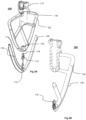
- Fig. 5A shows an attachment in the form of a whisk 410 having a removable universal identifier and data transmitter assembly 430 attached thereto.
- the removable universal identifier and data transmitter assembly 430 identifies the type of attachment it is attached to, that being a whisk 430 in the illustrated case, and transmits data associated with that identity to a receiver (not shown) in the stand mixer 100.
- Fig. 5B shows only a bayonet collar 412 of the whisk 410 for attaching to the shaft 131 ( Fig. 1A ) of the mixer 100, and the universal identifier and data transmitter assembly 430 removed therefrom.
- the collar 412 has a slot 413 for receiving an identifier part 420 having contacts 414 moulded therein.
- the removable universal identifier and data transmitter assembly 430 when attached to the removable attachment (i.e. the whisk 410 in the illustrated example), uses the configuration of the contacts 414 on the identifier part 420 to identify the type of attachment.
- the array of contacts 414 is adapted to encode an identity for the type of attachment.
- the removable universal identifier and data transmitter assembly 430 is preferably powered using WPT in a manner described with reference to Fig. 2 .
- the controller of the mixer 100 may use the identity of the type of attachment 410 being used, for example, to set the maximum speed or speed intervals available for use by the user. Additionally or alternatively, in the event where the controller provides recipe information, and/or appliance control based on the recipes, the group of recipes provided to the user (e.g. via the user interface 123 of the mixer 100, or via an associated application on the remote computer device) may be determined based on the attachment in use. For example, if the attachment is identified to be a dough hook, dough recipes are provided on a recipe application associated with the stand mixer 100 so that the user can select one of those recipes to be executed. Some recipes may require more than one accessory to be used.
- sensors are placed on attachments that rotate relative to the stand mixer 100, such as beater 140 and whish 410. Also described are sensors place on "attachments" that do not rotate in use, such as adding sensors to the inside of the bowl 110 to measure properties of the content 150 of the bowl 110 while being in contact with the content 150.
- the above description describes the stand mixer 100 in detail.
- the disclosure above may equally be implemented in a large selection of other possible kitchen appliances.
- the disclosure above may equally be implemented in food processors, or in blenders whether heated or not, and more particularly having sensors inside a removable container.
- the disclosure above may equally be implemented in ice cream makers and bread makers, with sensors applied either to a bowl or bread pan respectively, or to attachments mixing the content.
- the kitchen appliance includes the ability to "play back" a sequence of user or default factory settings.
- the parameters associated with certain food characteristics that are sensed by the sensors in direct contact with the content of the kitchen appliance may be used as an input to controlling the play back.
- the controller of the appliance determines when to transition from one recipe step to the next based on the measured temperature derived from the sensors.
- One reason why current kitchen appliances do not provide this functionality is because the temperature cannot be measured accurately enough in an appliance that has a moving mixing or blending attachment. This is at least in part because temperature sensors are positioned outside the container, either because of the difficulties in using a temperature probe when there is a moving blade or mixer, or because fixed sensors inside the container (in direct contact with the contents of the container) have not been considered either feasible or useful for kitchen appliances.
- the present inventors have found that measuring characteristics of the content being mixed or processed is not only possible (e.g. by incorporating the sensors in a position where the food is contacted), but can also be done accurately because a sensor positioned on a moving blade or mixing attachment is, under some processing circumstances, more likely to provide an accurate measurement (e.g. as opposed to measuring "cold spots” or "hot spots” of heated food contents.)
- the measured characteristic(s) can be used in the direct feedback to the controller that controls operation of the kitchen appliance (e.g. temperature measurements that provide feedback to a heating controller), but can also be used as a useful data input to a recipe play back functionality.
- the controller of the mixer 100 uses temperature data received from the temperature sensors 112 positioned on the beater 140 as feedback to control the temperature of the content 150.
- the mixer 100 also includes one or more temperature sensors (not illustrated) associated with the bowl, allowing the temperature of the bowl that is being heated also to be measured. Temperature measurements taken with the bowl temperature sensor(s) are also used as feedback to the controller.
- the controller uses the different temperature measurements to calculate a rate of change, and then relies on equilibrium or steady state temperature values (i.e. once the rate of change drops below a certain threshold). Because the sensors 112 on the beater 140 move around the content 150 that is being heated and has pockets of different temperatures, the sensed temperatures are initially variable. For this reason, the controller determines a steady state before relying on those measurements.
- the measured values may be averaged over time, over predefined time intervals, or over time once a steady state temperature is approached.
- the appliance is a heated bench mixer, and the heated bench mixer is used for tempering chocolate.
- the process of tempering chocolate is used to ensure a smooth surface and consistent texture of chocolate by managing the crystallization of the cocoa butter.
- Fig. 6A shows an example of a preparation profile (i.e. agitation speed) recorded on the bench mixer. More particularly, the preparation profile is used for tempering a small amount of chocolate.
- the chocolate has an initial temperature of approximately 20 degrees (room temperature) at time 0.
- the bench mixer sets the heating temperature to around 45 degrees at time 0, and based on a small amount of chocolate the set temperature is predicted to be reached at around 120 seconds.
- the bench mixer also agitates the contents of the mixing bowl 5 times, at speeds ranging between 25 and 100 RPM.
- the preparation profile at time 120 seconds includes a 50 second medium speed (120 RPM) agitation period used to mix the melted chocolate well. If seed chocolate (room temperature well-tempered chocolate) is added at this stage, this mixing section will incorporate that seed chocolate into the melted chocolate. At 120 seconds, heating is switched off so that the melted chocolate can cool down to room temperature. With the temperature sensor on the mixing accessory immersed in the melted chocolate, the bench mixer is able to sense when room temperature is approached.
- 120 RPM medium speed
- the mixer agitates the cooling chocolate to ensure an even consistency of the cooling chocolate.
- the temperature sensor is also better able to sense the average temperature throughout the cooling chocolate (as opposed to the temperature at one specific place in the mixing bowl).
- the predicted cooling time lasts until 300 seconds.
- the immersed sensor senses that the cooling chocolate is approaching room temperature, and the heated bench mixer sets the set temperature to 28 degrees to ensure that the cooling chocolate does not begin to recrystallise.
- the mixing accessory once again is set to agitate the chocolate for 10 seconds at about 60 RPM to improve the reliability of the sensed temperature.
- the bench mixer then changes the set temperature to 32 degrees ( ⁇ 1 degree) to ensure that the chocolate is heated and maintained in a range of 31-33 degrees so that appropriate crystallization of the cocoa fat will occur to temper the chocolate properly.
- the set temperature is changed at around 300 seconds, and the second heating stage, commences. It will be appreciated that such accurate temperature control ( ⁇ 1 degree) is very difficult, if not impossible, if only the temperature of the surface of the bowl is measured, without using an in-food sensor.
- the regular and controlled movement of the sensor through the contents of the bowl further adds to the accuracy of the temperature measurements.
- the set temperature is reached at around 360 seconds, after which the tempered chocolate is maintained within the 31-33 temperature range, and is periodically agitated to ensure the even distribution of temperature during the use of the tempered chocolate. This final stage is maintained for as long as the user requires the chocolate at this temperature during use, e.g. for 5-10 minutes, or 10-20 minutes.
- the chocolate used may deviate from the assumed model, e.g. more than 100 grams is used, or characteristics of the chocolate may differ such as starting temperature of refrigerated chocolate, high cocoa solid content, or fat characteristics resulting in a higher melting point. If this happens, the preparation profile as shown in Figure 1 will be adapted by the bench mixer based on sensor measurements taken during the preparation process.
- the bench mixer's heating means will operate with increased power.
- the melting chocolate temperature during the first heating stage e.g. at 60 seconds, as well as the heating rate (as determined from successive measurements during Stage 1) are both higher than expected by the original preparation profile.
- the bench mixer is able to adapt the profile accordingly. Because the temperature is being measured continually with the immersed in-food sensor, feedback to the controller is provided in a timely fashion, enabling more control over the preparation process.
- the temperature sensor provides the controller with measured parameters continuously. In other examples, the temperature sensor provides the controller with measured parameters with a certain period, e.g. every 10 seconds, every 30 seconds, every minute, etc. In some examples the user is able to select the sensing period.
- the controller is able to adapt the operation of the heating means, e.g. by switching the heating means off before 120 seconds to cool the melted chocolate, for example at around 90 seconds. This way overheating of the chocolate may be prevented.
- the controller of the bench mixer will change the operation of the bench mixer so that the cooling stage (between 120 seconds and 300 seconds in Fig. 6A ) lasts longer as it takes longer for 28 degrees to be reached.
- the controller in addition to being able to change the temperature profile by modifying the operation of the heating means, the controller is also able to modify the operation of the mixing accessory.
- the mixing accessory As illustrated in Fig. 6B , by increasing the rate and/or duration for the periods of agitation (as shown in black), the ingredients will be less likely to burn on the bowl wall, and agitating the ingredients more vigorously will promote cooling. Conversely, reduced motor speed will increase the time for ingredient heating if required.
- the cooling stage can also be extended if required for the melted chocolate to return to 28 degrees (with or without additional agitation).
- frozen desserts are made in an ice cream maker (e.g. sorbet, frozen yoghurt, gelato or ice cream).
- ice cream maker e.g. sorbet, frozen yoghurt, gelato or ice cream.
- Such frozen desserts set at different times depending on the ingredients and hardness requirements. For example, in addition to the volume of dessert introduced into the ice cream maker, the amount of sugar in a mixture will greatly affect the rate in which the dessert mixture sets.
- the mix-ins In the dessert mixture, it is preferable to add the mix-ins at a prescribed time. It is usually towards the end of a cycle to ensure that the churning action does not 'break down' or 'pulverise' the mix-in ingredients (e.g. soft fruits), but also have enough time to adequately mix the ingredients through the dessert mixture to allow for even distribution. Additionally, the ice cream maker should also ensure that the dessert mixture is not too 'frozen' as to allow the distribution of the mix-in ingredients. The ideal time could approximately be 1 minute prior to the completion of the dessert making cycle, for example.
- Load cells on the mixing paddle of the ice cream maker determine the consistency of the mixture through deflection of the paddle arm resisting the load applied (which changes because of the changing viscosity of the ingredients), while temperature sensors on the mixing paddle and/or on the inside of the bowl of the ice cream maker determine the temperature of the dessert mixture.
- the additional information and accuracy of the sensed data allows the ice cream maker to better approximate the ideal time to introduce mix-ins or to complete the recipe.
- Another example relates to an induction cooktop or a heated blender. If the quantity of ingredients is known (even to the extent of a look-up table when scaling recipes), the time to progress in a recipe would be prescribed. However, when the user places different amounts of ingredients to that prescribed in the recipe (including, for example, varying ratios of ingredients), or the temperature of the ingredients is different (for example, onions that have been stored in the fridge or ones stored at room temperature), sensed food characteristics are helpful in adapting recipe programs.
- a sensed temperature provides a useful input for recipe step progression as an alternative for time. For example, in a recipe that includes a step for sautéing onions, the controller will wait until the sensed temperature reaches 150°C (for a time interval between 3 mins and a maximum of 15mins) before proceeding to the next step.
- a level sensor or moisture sensor
- a timer may be used in conjunction with a level sensor.
- the level sensor will sense when the eggs have been volumised. The next step of whipping the sugar and eggs together will continue until the temperature sensor indicates that the mousse has cooled to around 40 degrees.
Claims (4)
- Ein Küchengerät zum Verarbeiten von Inhalt, wobei das Küchengerät folgende Merkmale aufweist:ein entfernbares Zubehör (140, 410), das durch den Körperabschnitt (120, 122, 130) aufgenommen wird;eine Senderanordnung, die angepasst ist, mit dem entfernbaren Zubehör (140, 410) zusammenzuwirken zum Identifizieren des entfernbaren Zubehörs (140, 410) und zum Senden von Daten, die einer Identät des entfernbaren Zubehörs (140, 410) zugeordnet sind; undeinen Empfänger, der dem Körperabschnitt zugeordnet ist, zum Empfangen der Daten, die der Identät zugeordnet sind;dadurch gekennzeichnet, dass das entfernbare Zubehör (140, 410) eine Einfassung (412) mit einem Schlitz (413) zum Aufnehmen eines Identifiziererteils (420) aufweist, wobei in dem Identifiziererteil ein oder mehrere Metallkontakte (414) geformt sind, undwobei die Senderanordnung eine Sensoranordnung zum Erfassen der Metallkon-takte (414) aufweist, wobei eine Konfiguration des einen oder der mehreren Metallkontakte (414) die Identät codiert.
- Das Küchengerät gemäß Anspruch 1, das ferner eine Steuerung zum Steuern eines Betriebs des Küchengeräts basierend auf der Identät aufweist, wobei die Steuerung die Identät verwendet, um einen Geschwindigkeitsparameter und eine Heiztemperatur des Küchengeräts einzustellen.
- Das Küchengerät gemäß Anspruch 2, bei dem die Steuerung die Identität verwendet, um einem Nutzer eine Gruppe von Rezepten zu präsentieren, die dem entfernbaren Zubehör (140, 410) zugeordnet sind.
- Das Küchengerät gemäß einem der Ansprüche 1 bis 3, bei dem die Senderanordnung entfernbar ist.
Applications Claiming Priority (2)
| Application Number | Priority Date | Filing Date | Title |
|---|---|---|---|
| AU2015902693A AU2015902693A0 (en) | 2015-07-08 | Kitchen appliance for sensing food and beverage properties | |
| PCT/AU2016/000244 WO2017004661A1 (en) | 2015-07-08 | 2016-07-06 | Kitchen appliance for sensing food and beverage properties |
Publications (3)
| Publication Number | Publication Date |
|---|---|
| EP3319496A1 EP3319496A1 (de) | 2018-05-16 |
| EP3319496A4 EP3319496A4 (de) | 2019-03-27 |
| EP3319496B1 true EP3319496B1 (de) | 2023-11-15 |
Family
ID=57684673
Family Applications (1)
| Application Number | Title | Priority Date | Filing Date |
|---|---|---|---|
| EP16820557.3A Active EP3319496B1 (de) | 2015-07-08 | 2016-07-06 | Küchengerät |
Country Status (6)
| Country | Link |
|---|---|
| US (1) | US11213170B2 (de) |
| EP (1) | EP3319496B1 (de) |
| CN (1) | CN107847086B (de) |
| AU (2) | AU2016290887B2 (de) |
| RU (1) | RU2722120C2 (de) |
| WO (1) | WO2017004661A1 (de) |
Families Citing this family (10)
| Publication number | Priority date | Publication date | Assignee | Title |
|---|---|---|---|---|
| EP3525641B1 (de) * | 2016-10-13 | 2021-07-07 | Breville Pty Limited | Aufschlagsvorgangsüberwachung eines standmixers |
| US11039715B2 (en) * | 2017-07-05 | 2021-06-22 | Illinois Tool Works Inc. | Food processing machine adaptive to food load |
| IT201700086975A1 (it) | 2017-07-28 | 2019-01-28 | Freni Brembo Spa | Metodo per realizzare un disco freno e disco freno per freni a disco |
| FR3083686B1 (fr) * | 2018-07-11 | 2020-06-19 | Seb S.A. | Appareil de preparation culinaire comprenant une cuve et un organe de travail |
| DE102018217416A1 (de) * | 2018-10-11 | 2020-04-16 | BSH Hausgeräte GmbH | Küchengerät mit adaptiver Einstellung eines Betriebsparameters |
| CN114007473A (zh) * | 2019-12-12 | 2022-02-01 | 皇家飞利浦有限公司 | 智能食物加工装置及方法 |
| US11963637B2 (en) * | 2020-03-31 | 2024-04-23 | Midea Group Co., Ltd. | Multi-purpose handheld kitchen appliance |
| FR3112668A1 (fr) * | 2020-07-26 | 2022-01-28 | Patrick Herbault | Dispositif de pilotage de l'élaboration de crème glacée dans une sorbetière par un capteur de température infra-rouge |
| USD990236S1 (en) | 2021-06-21 | 2023-06-27 | Whirlpool Corporation | Beater attachment |
| USD1010392S1 (en) * | 2021-12-30 | 2024-01-09 | Caiying Li | Flex edge beater |
Family Cites Families (30)
| Publication number | Priority date | Publication date | Assignee | Title |
|---|---|---|---|---|
| EP0589093A1 (de) * | 1992-09-22 | 1994-03-30 | Sigma-Delta N.V. | Küchenmaschine mit intelligentem Mischwerkzeug |
| US5746114A (en) * | 1995-08-15 | 1998-05-05 | Harris; David P. | Intelligent cooking system with wireless control |
| US6465432B1 (en) * | 2000-08-28 | 2002-10-15 | Kraft Food Holdings, Inc. | Isolated antioxidant peptides form casein and methods for preparing, isolating, and identifying antioxidant peptides |
| US8529118B2 (en) | 2001-04-13 | 2013-09-10 | Sunbeam Products, Inc. | Blender cup with lid storage |
| US7278545B2 (en) * | 2002-03-05 | 2007-10-09 | Chep Technology Pty Limited | Interchangeable fitment apparatus and system |
| GB0711752D0 (en) | 2007-06-18 | 2007-07-25 | Otter Controls Ltd | Electrical appliances |
| DE102008038833B4 (de) | 2008-08-13 | 2014-02-27 | Hans Heidolph Gmbh & Co. Kg | Laborrührer |
| FR2956009B1 (fr) | 2010-02-10 | 2013-01-04 | Michel Marcel Andre Loiselet | Dispositif de preparation culinaire avec melange des ingredients contenus dans celui-ci et mesure integree de la temperature du melange |
| US20120230149A1 (en) * | 2010-02-15 | 2012-09-13 | Peter Martin | Methods, systems and apparatus for promoting the pourability of semi-frozen and semi-fluidic beverages from beverage containers |
| US9259122B2 (en) * | 2010-02-15 | 2016-02-16 | Peter Martin | Methods, systems and apparatus for promoting the pourability of semi-frozen and semi-fluidic beverages from beverage containers |
| US8596308B2 (en) * | 2010-11-08 | 2013-12-03 | John Bean Technologies Corporation | Method and apparatus for aseptic filling of food product |
| SI23686A (sl) | 2011-03-03 | 2012-09-28 | Albin Smrke | Univerzalna naprava za regulacijo energije v obliki gumba |
| ES1075104Y (es) | 2011-06-21 | 2011-11-11 | Sammic Sl | Maquina combinada procesadora de alimentos |
| CN202234932U (zh) | 2011-09-13 | 2012-05-30 | 九阳股份有限公司 | 一种制浆安全的料理机 |
| DE102011053990A1 (de) * | 2011-09-27 | 2013-03-28 | Vorwerk & Co. Interholding Gmbh | Verfahren zur benutzerdefinierten Freischaltung einer elektrischen Küchenmaschine sowie elektrisch betriebene Küchenmaschine |
| CN102366308A (zh) * | 2011-10-11 | 2012-03-07 | 南通芯迎设计服务有限公司 | 狭缝式鸡蛋处理器 |
| CN103054482B (zh) | 2012-01-06 | 2015-04-15 | 惠阳亚伦塑胶电器实业有限公司 | 一种可识别刀具的食品加工机及加工刀具识别控制方法 |
| CN104205137B (zh) * | 2012-04-07 | 2018-08-28 | 三星电子株式会社 | 向与产品相关的装置提供控制信息的系统和方法 |
| US9326544B2 (en) * | 2012-06-06 | 2016-05-03 | Momentum Machines Company | System and method for dispensing toppings |
| AU2013277942B2 (en) * | 2012-06-22 | 2018-03-01 | Breville Pty Limited | Improved bench mixer |
| CN104486979A (zh) | 2012-07-18 | 2015-04-01 | 皇家飞利浦有限公司 | 豆浆机及用于制作豆浆的方法 |
| WO2014075923A1 (en) | 2012-11-14 | 2014-05-22 | Arcelik Anonim Sirketi | A food preparation appliance operated on an induction heating cooktop |
| EP4316324A3 (de) * | 2013-03-15 | 2024-03-13 | Vita-Mix Management Corporation | Elektrisch betriebener mischbehälter |
| CN103142089A (zh) * | 2013-03-23 | 2013-06-12 | 钟伟 | 有食物信息标识的餐具 |
| WO2014201509A2 (en) * | 2013-06-19 | 2014-12-24 | Breville Pty Limited | Improved cooking apparatus and method |
| EP3021956B1 (de) | 2013-07-16 | 2019-08-21 | Breville PTY Limited | Verbesserte eismaschine |
| AU2014101657B4 (en) | 2013-09-26 | 2020-02-06 | Newell Australia Pty Ltd | Kitchen appliance |
| US9943190B2 (en) | 2014-08-08 | 2018-04-17 | Sharkninja Operating Llc | Food processing apparatus and method |
| US10524614B2 (en) * | 2014-10-07 | 2020-01-07 | Whirlpool Corporation | Powered cooking accessory for an oven cavity |
| CN204288000U (zh) | 2014-12-05 | 2015-04-22 | 筷子兄弟科技有限公司 | 智能烹饪厨具、以及锅具 |
-
2016
- 2016-07-06 EP EP16820557.3A patent/EP3319496B1/de active Active
- 2016-07-06 AU AU2016290887A patent/AU2016290887B2/en active Active
- 2016-07-06 RU RU2018104577A patent/RU2722120C2/ru active
- 2016-07-06 WO PCT/AU2016/000244 patent/WO2017004661A1/en active Application Filing
- 2016-07-06 CN CN201680044232.4A patent/CN107847086B/zh active Active
- 2016-07-06 US US15/742,866 patent/US11213170B2/en active Active
-
2021
- 2021-07-28 AU AU2021209231A patent/AU2021209231A1/en active Pending
Also Published As
| Publication number | Publication date |
|---|---|
| EP3319496A4 (de) | 2019-03-27 |
| EP3319496A1 (de) | 2018-05-16 |
| RU2018104577A (ru) | 2019-08-08 |
| AU2016290887A1 (en) | 2018-01-25 |
| AU2016290887B2 (en) | 2021-06-10 |
| WO2017004661A1 (en) | 2017-01-12 |
| CN107847086B (zh) | 2023-05-12 |
| US11213170B2 (en) | 2022-01-04 |
| AU2021209231A1 (en) | 2021-08-19 |
| RU2018104577A3 (de) | 2019-12-19 |
| US20180368622A1 (en) | 2018-12-27 |
| RU2722120C2 (ru) | 2020-05-26 |
| CN107847086A (zh) | 2018-03-27 |
Similar Documents
| Publication | Publication Date | Title |
|---|---|---|
| EP3319496B1 (de) | Küchengerät | |
| CN105705027B (zh) | 用于以受控方式制备具有充气或搅打质构的冷却食品的机器和系统 | |
| EP3021956B1 (de) | Verbesserte eismaschine | |
| US20220273141A1 (en) | Variable Temperature Blender | |
| EP3062629B1 (de) | Maschine, system und verfahren zur herstellung eines gekühlten süsswarenprodukts mit belüfteter textur | |
| JP6971232B2 (ja) | 焦げ付きを防止した流動性食品の加熱 | |
| US20060044935A1 (en) | Method and system for producing a temperature profile in a food preparation container | |
| US20130340456A1 (en) | Ice Cream Maker | |
| US20090223385A1 (en) | Home cheese curd making device | |
| CN219846092U (zh) | 混合系统 |
Legal Events
| Date | Code | Title | Description |
|---|---|---|---|
| STAA | Information on the status of an ep patent application or granted ep patent |
Free format text: STATUS: THE INTERNATIONAL PUBLICATION HAS BEEN MADE |
|
| PUAI | Public reference made under article 153(3) epc to a published international application that has entered the european phase |
Free format text: ORIGINAL CODE: 0009012 |
|
| STAA | Information on the status of an ep patent application or granted ep patent |
Free format text: STATUS: REQUEST FOR EXAMINATION WAS MADE |
|
| 17P | Request for examination filed |
Effective date: 20180104 |
|
| AK | Designated contracting states |
Kind code of ref document: A1 Designated state(s): AL AT BE BG CH CY CZ DE DK EE ES FI FR GB GR HR HU IE IS IT LI LT LU LV MC MK MT NL NO PL PT RO RS SE SI SK SM TR |
|
| AX | Request for extension of the european patent |
Extension state: BA ME |
|
| DAV | Request for validation of the european patent (deleted) | ||
| DAX | Request for extension of the european patent (deleted) | ||
| RIC1 | Information provided on ipc code assigned before grant |
Ipc: A47J 43/07 20060101AFI20181113BHEP Ipc: A47J 43/06 20060101ALI20181113BHEP Ipc: A47J 44/00 20060101ALI20181113BHEP |
|
| A4 | Supplementary search report drawn up and despatched |
Effective date: 20190222 |
|
| RIC1 | Information provided on ipc code assigned before grant |
Ipc: A47J 43/06 20060101ALI20190218BHEP Ipc: A47J 43/07 20060101AFI20190218BHEP Ipc: A47J 44/00 20060101ALI20190218BHEP |
|
| STAA | Information on the status of an ep patent application or granted ep patent |
Free format text: STATUS: EXAMINATION IS IN PROGRESS |
|
| 17Q | First examination report despatched |
Effective date: 20220119 |
|
| GRAP | Despatch of communication of intention to grant a patent |
Free format text: ORIGINAL CODE: EPIDOSNIGR1 |
|
| STAA | Information on the status of an ep patent application or granted ep patent |
Free format text: STATUS: GRANT OF PATENT IS INTENDED |
|
| INTG | Intention to grant announced |
Effective date: 20230525 |
|
| GRAS | Grant fee paid |
Free format text: ORIGINAL CODE: EPIDOSNIGR3 |
|
| GRAA | (expected) grant |
Free format text: ORIGINAL CODE: 0009210 |
|
| STAA | Information on the status of an ep patent application or granted ep patent |
Free format text: STATUS: THE PATENT HAS BEEN GRANTED |
|
| AK | Designated contracting states |
Kind code of ref document: B1 Designated state(s): AL AT BE BG CH CY CZ DE DK EE ES FI FR GB GR HR HU IE IS IT LI LT LU LV MC MK MT NL NO PL PT RO RS SE SI SK SM TR |
|
| REG | Reference to a national code |
Ref country code: CH Ref legal event code: EP Ref country code: GB Ref legal event code: FG4D |
|
| REG | Reference to a national code |
Ref country code: DE Ref legal event code: R096 Ref document number: 602016084167 Country of ref document: DE |
|
| REG | Reference to a national code |
Ref country code: IE Ref legal event code: FG4D |
|
| REG | Reference to a national code |
Ref country code: LT Ref legal event code: MG9D |
|
| REG | Reference to a national code |
Ref country code: NL Ref legal event code: MP Effective date: 20231115 |
|
| PG25 | Lapsed in a contracting state [announced via postgrant information from national office to epo] |
Ref country code: GR Free format text: LAPSE BECAUSE OF FAILURE TO SUBMIT A TRANSLATION OF THE DESCRIPTION OR TO PAY THE FEE WITHIN THE PRESCRIBED TIME-LIMIT Effective date: 20240216 |
|
| PG25 | Lapsed in a contracting state [announced via postgrant information from national office to epo] |
Ref country code: IS Free format text: LAPSE BECAUSE OF FAILURE TO SUBMIT A TRANSLATION OF THE DESCRIPTION OR TO PAY THE FEE WITHIN THE PRESCRIBED TIME-LIMIT Effective date: 20240315 |
|
| PG25 | Lapsed in a contracting state [announced via postgrant information from national office to epo] |
Ref country code: LT Free format text: LAPSE BECAUSE OF FAILURE TO SUBMIT A TRANSLATION OF THE DESCRIPTION OR TO PAY THE FEE WITHIN THE PRESCRIBED TIME-LIMIT Effective date: 20231115 |
|
| REG | Reference to a national code |
Ref country code: AT Ref legal event code: MK05 Ref document number: 1630958 Country of ref document: AT Kind code of ref document: T Effective date: 20231115 |
|
| PG25 | Lapsed in a contracting state [announced via postgrant information from national office to epo] |
Ref country code: NL Free format text: LAPSE BECAUSE OF FAILURE TO SUBMIT A TRANSLATION OF THE DESCRIPTION OR TO PAY THE FEE WITHIN THE PRESCRIBED TIME-LIMIT Effective date: 20231115 |
|
| PG25 | Lapsed in a contracting state [announced via postgrant information from national office to epo] |
Ref country code: AT Free format text: LAPSE BECAUSE OF FAILURE TO SUBMIT A TRANSLATION OF THE DESCRIPTION OR TO PAY THE FEE WITHIN THE PRESCRIBED TIME-LIMIT Effective date: 20231115 |
|
| PG25 | Lapsed in a contracting state [announced via postgrant information from national office to epo] |
Ref country code: ES Free format text: LAPSE BECAUSE OF FAILURE TO SUBMIT A TRANSLATION OF THE DESCRIPTION OR TO PAY THE FEE WITHIN THE PRESCRIBED TIME-LIMIT Effective date: 20231115 |
|
| PG25 | Lapsed in a contracting state [announced via postgrant information from national office to epo] |
Ref country code: NL Free format text: LAPSE BECAUSE OF FAILURE TO SUBMIT A TRANSLATION OF THE DESCRIPTION OR TO PAY THE FEE WITHIN THE PRESCRIBED TIME-LIMIT Effective date: 20231115 Ref country code: LT Free format text: LAPSE BECAUSE OF FAILURE TO SUBMIT A TRANSLATION OF THE DESCRIPTION OR TO PAY THE FEE WITHIN THE PRESCRIBED TIME-LIMIT Effective date: 20231115 Ref country code: IS Free format text: LAPSE BECAUSE OF FAILURE TO SUBMIT A TRANSLATION OF THE DESCRIPTION OR TO PAY THE FEE WITHIN THE PRESCRIBED TIME-LIMIT Effective date: 20240315 Ref country code: GR Free format text: LAPSE BECAUSE OF FAILURE TO SUBMIT A TRANSLATION OF THE DESCRIPTION OR TO PAY THE FEE WITHIN THE PRESCRIBED TIME-LIMIT Effective date: 20240216 Ref country code: ES Free format text: LAPSE BECAUSE OF FAILURE TO SUBMIT A TRANSLATION OF THE DESCRIPTION OR TO PAY THE FEE WITHIN THE PRESCRIBED TIME-LIMIT Effective date: 20231115 Ref country code: BG Free format text: LAPSE BECAUSE OF FAILURE TO SUBMIT A TRANSLATION OF THE DESCRIPTION OR TO PAY THE FEE WITHIN THE PRESCRIBED TIME-LIMIT Effective date: 20240215 Ref country code: AT Free format text: LAPSE BECAUSE OF FAILURE TO SUBMIT A TRANSLATION OF THE DESCRIPTION OR TO PAY THE FEE WITHIN THE PRESCRIBED TIME-LIMIT Effective date: 20231115 Ref country code: PT Free format text: LAPSE BECAUSE OF FAILURE TO SUBMIT A TRANSLATION OF THE DESCRIPTION OR TO PAY THE FEE WITHIN THE PRESCRIBED TIME-LIMIT Effective date: 20240315 |