EP3318332B1 - Ensemble de projection pneumatique, restricteur pour un tel ensemble et installation de projection de produit de revêtement comprenant un tel ensemble ou un tel restricteur - Google Patents
Ensemble de projection pneumatique, restricteur pour un tel ensemble et installation de projection de produit de revêtement comprenant un tel ensemble ou un tel restricteur Download PDFInfo
- Publication number
- EP3318332B1 EP3318332B1 EP17199970.9A EP17199970A EP3318332B1 EP 3318332 B1 EP3318332 B1 EP 3318332B1 EP 17199970 A EP17199970 A EP 17199970A EP 3318332 B1 EP3318332 B1 EP 3318332B1
- Authority
- EP
- European Patent Office
- Prior art keywords
- restrictor
- coating product
- sprayer
- supply line
- pressure
- Prior art date
- Legal status (The legal status is an assumption and is not a legal conclusion. Google has not performed a legal analysis and makes no representation as to the accuracy of the status listed.)
- Active
Links
- 239000011248 coating agent Substances 0.000 title claims description 71
- 238000000576 coating method Methods 0.000 title claims description 71
- 238000005507 spraying Methods 0.000 title claims description 21
- 238000009434 installation Methods 0.000 title claims description 18
- 238000011144 upstream manufacturing Methods 0.000 claims description 15
- 239000000463 material Substances 0.000 claims description 11
- 229920002994 synthetic fiber Polymers 0.000 claims description 3
- 230000007423 decrease Effects 0.000 claims description 2
- 230000008878 coupling Effects 0.000 claims 4
- 238000010168 coupling process Methods 0.000 claims 4
- 238000005859 coupling reaction Methods 0.000 claims 4
- 230000000295 complement effect Effects 0.000 description 3
- 230000000694 effects Effects 0.000 description 2
- 239000007788 liquid Substances 0.000 description 2
- 230000001105 regulatory effect Effects 0.000 description 2
- 238000007789 sealing Methods 0.000 description 2
- 238000010146 3D printing Methods 0.000 description 1
- 229910001369 Brass Inorganic materials 0.000 description 1
- 229910000906 Bronze Inorganic materials 0.000 description 1
- 208000031968 Cadaver Diseases 0.000 description 1
- 229910000831 Steel Inorganic materials 0.000 description 1
- 239000010951 brass Substances 0.000 description 1
- 239000010974 bronze Substances 0.000 description 1
- 238000004891 communication Methods 0.000 description 1
- 230000001276 controlling effect Effects 0.000 description 1
- KUNSUQLRTQLHQQ-UHFFFAOYSA-N copper tin Chemical compound [Cu].[Sn] KUNSUQLRTQLHQQ-UHFFFAOYSA-N 0.000 description 1
- 229920001971 elastomer Polymers 0.000 description 1
- 239000000806 elastomer Substances 0.000 description 1
- 238000003780 insertion Methods 0.000 description 1
- 230000037431 insertion Effects 0.000 description 1
- 238000003754 machining Methods 0.000 description 1
- 238000012423 maintenance Methods 0.000 description 1
- 230000014759 maintenance of location Effects 0.000 description 1
- 239000002184 metal Substances 0.000 description 1
- 238000000465 moulding Methods 0.000 description 1
- 210000000056 organ Anatomy 0.000 description 1
- 230000007425 progressive decline Effects 0.000 description 1
- 230000000284 resting effect Effects 0.000 description 1
- 239000007921 spray Substances 0.000 description 1
- 239000010959 steel Substances 0.000 description 1
- 239000002699 waste material Substances 0.000 description 1
- XLYOFNOQVPJJNP-UHFFFAOYSA-N water Substances O XLYOFNOQVPJJNP-UHFFFAOYSA-N 0.000 description 1
- 239000002023 wood Substances 0.000 description 1
Images


Classifications
-
- B—PERFORMING OPERATIONS; TRANSPORTING
- B05—SPRAYING OR ATOMISING IN GENERAL; APPLYING FLUENT MATERIALS TO SURFACES, IN GENERAL
- B05B—SPRAYING APPARATUS; ATOMISING APPARATUS; NOZZLES
- B05B9/00—Spraying apparatus for discharge of liquids or other fluent material, without essentially mixing with gas or vapour
- B05B9/03—Spraying apparatus for discharge of liquids or other fluent material, without essentially mixing with gas or vapour characterised by means for supplying liquid or other fluent material
-
- B—PERFORMING OPERATIONS; TRANSPORTING
- B05—SPRAYING OR ATOMISING IN GENERAL; APPLYING FLUENT MATERIALS TO SURFACES, IN GENERAL
- B05B—SPRAYING APPARATUS; ATOMISING APPARATUS; NOZZLES
- B05B1/00—Nozzles, spray heads or other outlets, with or without auxiliary devices such as valves, heating means
- B05B1/30—Nozzles, spray heads or other outlets, with or without auxiliary devices such as valves, heating means designed to control volume of flow, e.g. with adjustable passages
- B05B1/3033—Nozzles, spray heads or other outlets, with or without auxiliary devices such as valves, heating means designed to control volume of flow, e.g. with adjustable passages the control being effected by relative coaxial longitudinal movement of the controlling element and the spray head
- B05B1/304—Nozzles, spray heads or other outlets, with or without auxiliary devices such as valves, heating means designed to control volume of flow, e.g. with adjustable passages the control being effected by relative coaxial longitudinal movement of the controlling element and the spray head the controlling element being a lift valve
- B05B1/3046—Nozzles, spray heads or other outlets, with or without auxiliary devices such as valves, heating means designed to control volume of flow, e.g. with adjustable passages the control being effected by relative coaxial longitudinal movement of the controlling element and the spray head the controlling element being a lift valve the valve element, e.g. a needle, co-operating with a valve seat located downstream of the valve element and its actuating means, generally in the proximity of the outlet orifice
-
- B—PERFORMING OPERATIONS; TRANSPORTING
- B05—SPRAYING OR ATOMISING IN GENERAL; APPLYING FLUENT MATERIALS TO SURFACES, IN GENERAL
- B05B—SPRAYING APPARATUS; ATOMISING APPARATUS; NOZZLES
- B05B12/00—Arrangements for controlling delivery; Arrangements for controlling the spray area
- B05B12/004—Arrangements for controlling delivery; Arrangements for controlling the spray area comprising sensors for monitoring the delivery, e.g. by displaying the sensed value or generating an alarm
- B05B12/006—Pressure or flow rate sensors
-
- B—PERFORMING OPERATIONS; TRANSPORTING
- B05—SPRAYING OR ATOMISING IN GENERAL; APPLYING FLUENT MATERIALS TO SURFACES, IN GENERAL
- B05B—SPRAYING APPARATUS; ATOMISING APPARATUS; NOZZLES
- B05B7/00—Spraying apparatus for discharge of liquids or other fluent materials from two or more sources, e.g. of liquid and air, of powder and gas
- B05B7/02—Spray pistols; Apparatus for discharge
- B05B7/04—Spray pistols; Apparatus for discharge with arrangements for mixing liquids or other fluent materials before discharge
- B05B7/0416—Spray pistols; Apparatus for discharge with arrangements for mixing liquids or other fluent materials before discharge with arrangements for mixing one gas and one liquid
-
- B—PERFORMING OPERATIONS; TRANSPORTING
- B05—SPRAYING OR ATOMISING IN GENERAL; APPLYING FLUENT MATERIALS TO SURFACES, IN GENERAL
- B05B—SPRAYING APPARATUS; ATOMISING APPARATUS; NOZZLES
- B05B7/00—Spraying apparatus for discharge of liquids or other fluent materials from two or more sources, e.g. of liquid and air, of powder and gas
- B05B7/02—Spray pistols; Apparatus for discharge
- B05B7/12—Spray pistols; Apparatus for discharge designed to control volume of flow, e.g. with adjustable passages
-
- B—PERFORMING OPERATIONS; TRANSPORTING
- B05—SPRAYING OR ATOMISING IN GENERAL; APPLYING FLUENT MATERIALS TO SURFACES, IN GENERAL
- B05B—SPRAYING APPARATUS; ATOMISING APPARATUS; NOZZLES
- B05B7/00—Spraying apparatus for discharge of liquids or other fluent materials from two or more sources, e.g. of liquid and air, of powder and gas
- B05B7/24—Spraying apparatus for discharge of liquids or other fluent materials from two or more sources, e.g. of liquid and air, of powder and gas with means, e.g. a container, for supplying liquid or other fluent material to a discharge device
- B05B7/2489—Spraying apparatus for discharge of liquids or other fluent materials from two or more sources, e.g. of liquid and air, of powder and gas with means, e.g. a container, for supplying liquid or other fluent material to a discharge device an atomising fluid, e.g. a gas, being supplied to the discharge device
-
- B—PERFORMING OPERATIONS; TRANSPORTING
- B05—SPRAYING OR ATOMISING IN GENERAL; APPLYING FLUENT MATERIALS TO SURFACES, IN GENERAL
- B05B—SPRAYING APPARATUS; ATOMISING APPARATUS; NOZZLES
- B05B9/00—Spraying apparatus for discharge of liquids or other fluent material, without essentially mixing with gas or vapour
- B05B9/007—At least a part of the apparatus, e.g. a container, being provided with means, e.g. wheels, for allowing its displacement relative to the ground
-
- B—PERFORMING OPERATIONS; TRANSPORTING
- B05—SPRAYING OR ATOMISING IN GENERAL; APPLYING FLUENT MATERIALS TO SURFACES, IN GENERAL
- B05B—SPRAYING APPARATUS; ATOMISING APPARATUS; NOZZLES
- B05B9/00—Spraying apparatus for discharge of liquids or other fluent material, without essentially mixing with gas or vapour
- B05B9/03—Spraying apparatus for discharge of liquids or other fluent material, without essentially mixing with gas or vapour characterised by means for supplying liquid or other fluent material
- B05B9/04—Spraying apparatus for discharge of liquids or other fluent material, without essentially mixing with gas or vapour characterised by means for supplying liquid or other fluent material with pressurised or compressible container; with pump
- B05B9/0403—Spraying apparatus for discharge of liquids or other fluent material, without essentially mixing with gas or vapour characterised by means for supplying liquid or other fluent material with pressurised or compressible container; with pump with pumps for liquids or other fluent material
Definitions
- the invention relates to a pneumatic spraying assembly for coating product intended for use in a spraying installation for coating product, as well as a restrictor forming a spare part for such an assembly and to an installation for spraying coating product. comprising such a projector and / or such a restrictor.
- a coating product spraying installation it is known practice to supply one or more manual or automatic projectors with a coating product under pressure, as well as with air for spraying this coating product.
- a pump capable of delivering both air under pressure and the coating product under pressure.
- each sprayer can be supplied by a hose of different length and / or diameter.
- pressure regulators are mounted on the pump or the pump part which delivers the coating product under pressure. The regulators are used to avoid or limit the pressure fluctuations in a coating product supply pipe to the projector and to adjust the pressures in each pipe independently, in order to obtain iso pressure at each projector.
- Certain coating products such as those used to apply a stain to wood, are very liquid, that is to say have a particularly low viscosity, close to that of water.
- the supply pressure of the spraying zone of a projector must be low, in particular less than 0.5 bar.
- a volume provided inside the body of a sprayer to supply this spraying zone must itself be at low pressure. This involves supplying the projector with a coating product at low pressure, which causes the regulator to operate outside its nominal pressure range, to the point that it is no longer efficient and no longer allows hide pump stroke reversals. This results in pressure fluctuations in the feed pipe to the projector, which leads to uneven application of the coating material.
- the invention more particularly intends to remedy by proposing a new assembly for pneumatic spraying of coating product which makes it possible to supply a spraying zone with a coating product under low pressure, without the risk of operating. a pressure relief valve outside its operating range.
- the invention relates to an assembly for pneumatic spraying of coating product
- a pneumatic sprayer of coating product and a line for supplying this pneumatic sprayer from a source of pressurized coating product to which the supply line is connected by its upstream end
- the pneumatic sprayer comprising a sprayer body and a valve for controlling the flow of the coating product to a spraying zone of this product, this valve itself comprising a needle of 'selective sealing of an outlet of an internal volume of the body of the projector and the projection assembly defining a flow path of the coating product, from the upstream end of the supply line to the internal volume outlet.
- the flow path includes a feed line connecting member to the projector body, while a coating material flow restrictor is mounted on the coating material flow path to create a waste. load upstream of the outlet.
- the restrictor is made of a material that is more flexible than the material of the connecting member, in particular of synthetic material.
- the pressure drop created by the restrictor upstream of the projector makes it possible to maintain a relatively high pressure in the upstream part of the coating product supply line from the projector, while the pressure in the internal volume of the body of the sprayer may be sufficiently low, in particular less than 0.7 bar, to allow low pressure supply to the spraying zone.
- a pressure regulator arranged at the outlet of a feed pump of the sprayer can be implemented in its nominal operating pressure range, so that it remains effective, even when the pressure of the sprayed coating product. is weak.
- the fact that the restrictor is made of a material that is softer than the material of the connecting member promotes sealing.
- the pressures indicated are relative and dynamic pressures, that is to say measured when the coating product circulates in the conduits and supply volume of the spray zone.
- the invention relates to a restrictor forming a spare part for an assembly as mentioned above.
- This restrictor is formed by a part which defines at least one calibrated flow conduit for coating product, the length of which is between 1 and 25 mm, preferably between 8 and 15 mm, more preferably of the order of 10 mm. , and whose maximum transverse dimension is less than 2 mm, preferably between 0.5 and 1.8 mm.
- one end of the restrictor, which defines a mouth thereof is of frustoconical outer and inner shapes, with angles at the top of the same value. This allows the restrictor to take place in a conventional member for connecting the projector with the supply line.
- the invention relates to a coating product spraying installation which comprises at least one coating product reservoir, at least one pneumatic coating product sprayer, a feed pump for at least one sprayer in coating product from the tank, as well as a supply line to the pneumatic projector from the pump.
- the pneumatic projector and the supply line form an assembly as mentioned above and / or include a restrictor as mentioned above.
- the restrictor makes it possible to create a controlled pressure drop and to obtain, within the installation, the same pressure in each projector, while using a single pressure regulator, even in the case where it there are several projectors connected to the same output of the regulator.
- the pump is equipped, at the outlet, with a pressure regulator set to deliver the coating product to a supply line of the coating product sprayer, at a pressure of between 0.5 and 3 bars, while the pressure restrictor is configured to deliver the coating product to the outlet of the internal volume of the projector body under a pressure less than 1 bar, preferably between 0.3 and 0.7 bar.
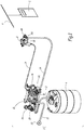
- Installation 2 shown in figure 1 is intended to coat objects O, such as wooden panels transported by a conveyor 4, with a liquid coating product stored in a tank 6.
- the installation 2 comprises a projector 8 which is here formed by a pneumatic gun, of the “Airspray” type, intended to be handled by an operator.
- the projector 8 is an automatic pneumatic Airspray type projector intended to be mounted on a support, possibly mobile, and controlled by an automatic device.
- the installation 2 also comprises a pump 10 connected to the reservoir 6 by a suction tube 12.
- the pump 10 is, moreover, connected to the projector 8 by a line 14 for supplying this projector with coating product under pressure.
- a pressure regulator 16 is mounted at the outlet of the pump 10, on the side of the line 14, and makes it possible to regulate the pressure of the coating product circulating in this line, as a function of a set value adjusted by means of a button 18. Note 141 the upstream end of line 14 via which this line is connected to regulator 16.
- the pump 10 delivers the coating product under a pressure of between 2 and 40 bars.
- the pressure regulator is constructed so that the setpoint is between 0.5 and 3 bar. In other words, the regulated pressure in the pipe 14 can normally be set between 0.3 and 3 bar.
- the pump 10 is connected to an air source 20 which may be a source of compressed air.
- An air suction tube 22 connects the source 20 to the pump 10.
- the lines 14 and 24 can be formed by flexible pipes.
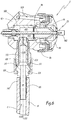
- the projector 8 comprises a body 82 on which is mounted a head or cap 84 immobilized by a nut 86, with the interposition of seals 88 and 90.
- the head 84 is intended to deliver a flat jet and for this purpose comprises two horns, only one of which is visible at the bottom. figure 2 with the references 842.
- the head is provided with air circulation channels coming from the pipe 24. Some of these channels are visible at figure 2 with the reference 844.
- the body 82 is, for its part, provided with channels 824 for circulating air from a zone of connection of the pipe 24 on the body 82 and up to the head 84. Only one of these channels is visible at the bottom. figure 2 , it being specified that the number and the representation of the channels 824 and 844 are not limiting any more than their number.
- the sprayer 8 comprises a valve 92 which makes it possible to control the output of coating product by means of a trigger 94.
- the valve comprises a needle 96 and a nozzle 98 which defines a seat 981 on which the needle 96 comes into play. support in the closed configuration of the valve 92 shown in figures 2 , 5 and 6 .
- the nozzle 98 cooperates with a jacket 100 disposed inside the body 2 to define a volume V82 internal to the body 82, which is intended to receive the coating product flowing towards an outlet orifice 982 of the nozzle 98. Downstream of this outlet orifice 982, there is formed a spraying zone Z8 of the sprayer 8 in which the coating product leaving the volume V82 through the orifice 982 is sprayed by the air coming from the channels 844 and shaped by the air coming from channels in the horns 842.
- a connecting member 102 is mounted on the body 82 such that its internal volume V102 is in communication with the volume 82.
- the member 102 is screwed onto the body 82.
- This connecting member 102 is intended for to be connected to the downstream end 142 of the supply pipe 14. It thus constitutes part of an inlet connection for the coating product in the body 82, more particularly in the volume V82.
- the member 102 is sometimes called “inlet connection”.
- the connecting member 102 is equipped with an external thread 104 intended to cooperate with a nut 106 mounted to rotate freely around a connecting element 108 provided with a crenellated rod inserted and immobilized by cooperation of shapes in the end. downstream 142 of the supply line 14.
- the elements 108 and 110 are visible at the figure 6 .
- the connecting member 102 is provided with a mouth 112 of frustoconical shape converging towards the body 82. Furthermore, the connecting element 108 is provided with a front surface 114 also frustoconical and of geometry complementary to that of the mouthpiece 112.
- a flow path C of coating material under pressure is defined between the end 141 of the line 14 and the orifice 982.
- This flow path C comprises the internal volume of the pipe forming the supply line 14, the internal volume V102 of organ 102 and internal volume V82.
- a restrictor 120 is mounted in the volume V102, that is to say within the flow path C, in order to create a pressure drop on the path of the coating product, upstream of the volume V82.
- the restrictor 120 is in one piece and has a circular section. Its external surface 122 is complementary to the internal surface 103 of the member 102 which is also of circular section. We denote respectively X102 and X120 of the longitudinal and central axes of the parts 102 and 120.
- the external surface 122 comprises a frustoconical section 122a of complementary shape to the mouth 112. In particular, the angle at the apex a122 of the section 122a is the same as the apex angle a112 of the mouth 112. This allows a surface support of the section 122a on the mouth 112.
- the restrictor 120 comprises a downstream end 124 which has the smallest outside diameter of the restrictor 120 and which is intended to be engaged to the bottom of the volume V102 towards the volume V82.
- the terminal surface 124a of the end 124 is in the form of an annular disc centered on the axis X120 of the restrictor 120 and pierced with an orifice 126 which constitutes the outlet of a calibrated duct 128 of circular section formed in the restrictor 120 and centered on the X120 axis.
- the surface 124a participates in the limitation of the volume V82.
- the upstream end of restrictor 120 opposite to the downstream end 124 and which defines a mouth 132 of this restrictor.
- This mouthpiece is tapered in shape.
- ⁇ 132 its angle at the top.
- the angles ⁇ 122 and a132 have the same value.
- the upstream end 130 of the restrictor 120 is of frustoconical exterior and interior shapes, with a constant thickness along its length except at the level of an end collar 134 which protrudes from the volume V102 in the mounted configuration of the restrictor 120 in the connecting member 102, as shown in figure 5 .
- angles ⁇ 112, ⁇ 122 and ⁇ 130 can have a value of between 45 and 70 °, preferably equal to 60 °.
- the restrictor 120 defines an internal volume V120, the diameter of which is denoted d120. This volume V120 forms a chamber for the passage of the coating product between the mouth 132 and the calibrated duct 128.
- L128 denotes the length of duct 128 measured parallel to the axis X120.
- the diameter of this duct is denoted by d128.
- L128 and d128 are selected so as to create a significant pressure drop during the passage of the coating product from the volume V120 to the volume V82.
- the length L128 is chosen between 1 and 25 mm, preferably between 8 and 15 mm, more preferably of the order of 10 mm, while the diameter d128 is chosen less than 2 mm, preferably between 0, 5 and 1.8 mm.
- the diameter d128 is strictly less than the diameter d120 and the internal surface 123 of the restrictor 120 comprises a frustoconical section 123b converging towards the mouth 127 of the calibrated duct 128.
- the frustoconical section 123B has the effect that the cross section of the flow path gradually decreases between that of the pipe forming the line 14, which is substantially equal to that of the interior volume V120, and that of the calibrated duct 128. This avoids creating nooks where the coating product could get stuck.
- the duct 128 is not of circular section.
- its maximum transverse dimension is selected as less than 2 mm, preferably between 0.5 and 1.8 mm.
- its maximum transverse dimension is equal to the diameter d128 of this duct 128.
- the apex half-angles ⁇ 102 and ⁇ 122 of the surfaces 102b and 122b are equal, with a value between 15 and 30 °, preferably equal to 20 °.
- the restrictor 120 is made by molding, machining or 3D printing of a synthetic material that is softer than the material constituting the fitting 102.
- the fitting 102 can be made of steel or brass, while the restrictor 102 is made of elastomer. This allows the restrictor 120 to adapt to the internal shape of the connecting member 102 and to ensure the seal between the parts 102 and 120.
- the restrictor 120 can be made of metal, for example bronze.
- the projector is in the configuration of the figure 5 where the outer surface 122 of the restrictor substantially matches the inner shape of the fitting 102, while the flange 134 projects from the volume V102.
- the member 102 is configured to cooperate with the elements 106 and 108 both in the absence of the restrictor 120 and in the presence of the restrictor 120 in the volume V102.
- the pressure P82 in the volume 82 can be much lower than the pressure P16 because a significant pressure drop is created by the restriction made up of the calibrated duct 128.
- the diameter d128 of the duct 128 can be chosen equal to 0.8 mm, 0.9 mm, 1 mm, 1.2 mm, 1.4 mm or 1.8 mm, which makes it possible to adapt the pressure P82 to the nature of the coating product to be sprayed, in particular its viscosity.
- the restrictor 120 constitutes a wearing part which can be mounted reversibly and without tools inside the connecting member 102 and which avoids the areas of retention of the coating product contained in its internal shape, in particular due to the progressive decrease in the passage section due to the frustoconical surface 123b.
- No tools are required to install restrictor 120 into fitting 102 by pushing it in the direction of arrow F1.
- a conventional wrench is sufficient to tighten the nut 106 on the connecting member 102.
- the connecting member 102 can be integral with the body 82 or fixed to the latter other than by screwing.
- the restrictor 120 can be integrated within the pipe constituting the supply line 14.
- this restrictor is preferably integrated into the flow path of the coating product in an area close to the outlet orifice 982, that is to say at most near the downstream end 142 of line 14 or within projector 8, as in the two embodiments shown in the figures.
- the installation of the restrictor 120 in the connection member 102, in the body 82 or elsewhere in the flow path C of the projector 8 therefore makes it possible to maintain a relatively high pressure P16 in a part upstream of the pipe which forms the pipe 14, while the pressure P82 of the coating product at the outlet of the volume V82 and the pressure of this product in the spraying zone Z8 are low and adapted to the viscosity of the sprayed coating product.
Landscapes
- Chemical & Material Sciences (AREA)
- Analytical Chemistry (AREA)
- Physics & Mathematics (AREA)
- Fluid Mechanics (AREA)
- Nozzles (AREA)
Applications Claiming Priority (1)
| Application Number | Priority Date | Filing Date | Title |
|---|---|---|---|
| FR1660689A FR3058331B1 (fr) | 2016-11-04 | 2016-11-04 | Ensemble de projection pneumatique, restricteur pour un tel ensemble et installation de projection de produit de revetement comprenant un tel ensemble ou un tel restricteur |
Publications (2)
| Publication Number | Publication Date |
|---|---|
| EP3318332A1 EP3318332A1 (fr) | 2018-05-09 |
| EP3318332B1 true EP3318332B1 (fr) | 2020-09-16 |
Family
ID=57963301
Family Applications (1)
| Application Number | Title | Priority Date | Filing Date |
|---|---|---|---|
| EP17199970.9A Active EP3318332B1 (fr) | 2016-11-04 | 2017-11-03 | Ensemble de projection pneumatique, restricteur pour un tel ensemble et installation de projection de produit de revêtement comprenant un tel ensemble ou un tel restricteur |
Country Status (9)
| Country | Link |
|---|---|
| US (1) | US10315207B2 (ru) |
| EP (1) | EP3318332B1 (ru) |
| JP (1) | JP7114238B2 (ru) |
| KR (1) | KR102447021B1 (ru) |
| CN (1) | CN108014940B (ru) |
| BR (1) | BR102017023557A2 (ru) |
| ES (1) | ES2829327T3 (ru) |
| FR (1) | FR3058331B1 (ru) |
| RU (1) | RU2753345C2 (ru) |
Families Citing this family (1)
| Publication number | Priority date | Publication date | Assignee | Title |
|---|---|---|---|---|
| DE102020002351A1 (de) * | 2020-04-19 | 2021-10-21 | Exel Industries Sa | Druckkopf mit mikropneumatischer Steuereinheit |
Family Cites Families (17)
| Publication number | Priority date | Publication date | Assignee | Title |
|---|---|---|---|---|
| US2504117A (en) * | 1945-08-24 | 1950-04-18 | Eclipse Air Brush Co | Method of spraying multicolored coatings |
| US2513081A (en) * | 1946-09-05 | 1950-06-27 | Sherwin Williams Co | Multichromatic spraying apparatus |
| US3645447A (en) * | 1968-12-31 | 1972-02-29 | Electrogasdynamics | Electrostatic paint spray system |
| JPS59102468A (ja) * | 1982-11-12 | 1984-06-13 | Konpon:Kk | スプレ−ガン |
| JPH0746359Y2 (ja) * | 1990-01-29 | 1995-10-25 | 岩田塗装機工業株式会社 | 内部混合式スプレーガンの塗料噴出量調節装置 |
| JP2599940Y2 (ja) * | 1993-10-28 | 1999-09-27 | トリニティ工業株式会社 | 塗装用スプレーガンの吐出量調整装置 |
| JP3371031B2 (ja) * | 1994-04-14 | 2003-01-27 | アネスト岩田株式会社 | スプレーガンおよび塗装装置 |
| US5836517A (en) * | 1995-01-03 | 1998-11-17 | Ransburg Corporation | Spray gun with fluid valve |
| JP3633233B2 (ja) * | 1996-11-12 | 2005-03-30 | 日産自動車株式会社 | エアスプレーガン |
| US5887801A (en) * | 1997-06-03 | 1999-03-30 | Stevens; Barry A. | High pressure hose recoil reduction device |
| US6179223B1 (en) * | 1999-08-16 | 2001-01-30 | Illinois Tool Works | Spray nozzle fluid regulator and restrictor combination |
| DE10250531A1 (de) * | 2002-10-29 | 2004-05-19 | ITW Oberflächentechnik GmbH & Co. KG | Spritzbeschichtungsvorrichtung für Beschichtungsflüssigkeit |
| US7757973B2 (en) * | 2005-04-04 | 2010-07-20 | Illinois Tool Works Inc. | Hand-held coating dispensing device |
| JP2010281431A (ja) * | 2009-06-08 | 2010-12-16 | Ntn Corp | 軸継手および等速自在継手 |
| FR2949983B1 (fr) * | 2009-09-14 | 2013-06-14 | Air Et Pulverisation | Dispositif de pulverisation de peinture |
| EP2929944A1 (de) * | 2014-04-08 | 2015-10-14 | J. Wagner GmbH | Farbsprüheinrichtung |
| CN105817353A (zh) * | 2016-05-20 | 2016-08-03 | 厦门建霖工业有限公司 | 一种限流装置及方法 |
-
2016
- 2016-11-04 FR FR1660689A patent/FR3058331B1/fr active Active
-
2017
- 2017-10-25 US US15/792,783 patent/US10315207B2/en active Active
- 2017-10-30 JP JP2017208876A patent/JP7114238B2/ja active Active
- 2017-10-31 BR BR102017023557-2A patent/BR102017023557A2/pt not_active Application Discontinuation
- 2017-11-02 RU RU2017138269A patent/RU2753345C2/ru active
- 2017-11-03 ES ES17199970T patent/ES2829327T3/es active Active
- 2017-11-03 CN CN201711070534.1A patent/CN108014940B/zh active Active
- 2017-11-03 KR KR1020170146131A patent/KR102447021B1/ko active IP Right Grant
- 2017-11-03 EP EP17199970.9A patent/EP3318332B1/fr active Active
Non-Patent Citations (1)
| Title |
|---|
| None * |
Also Published As
| Publication number | Publication date |
|---|---|
| CN108014940B (zh) | 2021-05-28 |
| RU2753345C2 (ru) | 2021-08-13 |
| EP3318332A1 (fr) | 2018-05-09 |
| KR20180050242A (ko) | 2018-05-14 |
| FR3058331A1 (fr) | 2018-05-11 |
| RU2017138269A (ru) | 2019-05-06 |
| FR3058331B1 (fr) | 2023-05-19 |
| US20180126397A1 (en) | 2018-05-10 |
| KR102447021B1 (ko) | 2022-09-23 |
| RU2017138269A3 (ru) | 2021-02-19 |
| US10315207B2 (en) | 2019-06-11 |
| CN108014940A (zh) | 2018-05-11 |
| JP7114238B2 (ja) | 2022-08-08 |
| ES2829327T3 (es) | 2021-05-31 |
| JP2018069238A (ja) | 2018-05-10 |
| BR102017023557A2 (pt) | 2018-05-29 |
Similar Documents
| Publication | Publication Date | Title |
|---|---|---|
| EP2986857B1 (fr) | Pompe a effet venturi et installation d'application de revetement de peinture | |
| CA2621843C (fr) | Controle d'alignement pour un systeme de decoupe par jet d'eau | |
| EP3686427A1 (fr) | Pompe pour produit liquide comprenant un dispositif d'étanchéité et installation de pulvérisation comprenant une telle pompe | |
| EP3318332B1 (fr) | Ensemble de projection pneumatique, restricteur pour un tel ensemble et installation de projection de produit de revêtement comprenant un tel ensemble ou un tel restricteur | |
| EP1386668B1 (fr) | Dispositif de pulvérisation d'eau sous forme d'un jet creux a paroi mince, pour la formation de neige artificielle | |
| FR3030464A1 (fr) | Dispositif distributeur de fluide et procede de fabrication d’un tel dispositif | |
| WO2017207902A1 (fr) | Chambre entre un embout d'entree et un obturateur, pour injecteur de turbomachine | |
| EP1683580B1 (fr) | Pistolet de projection ou d'enduction de matériau de construction | |
| EP3785803B1 (fr) | Vanne et système d'application de produit de revêtement comprenant une telle vanne | |
| EP0134726A1 (fr) | Valve de décharge brutale commandée par un piston | |
| FR2905611A1 (fr) | Buse de pulverisation,organe de distribution comprenant une telle buse,distributeur comprenant un tel organe de distribution et utilisation d'une telle buse. | |
| FR3073155A1 (fr) | Buse de pulverisation avec retrecissement de pre-atomisation, et tete de pulverisation et dispositif de pulverisation comprenant une telle buse | |
| EP3066371B1 (fr) | Dispositif d'alimentation d'un projecteur en produit de revetement liquide | |
| FR2459679A1 (fr) | Melangeur pour l'introduction d'un produit liquide en proportion determinee dans une canalisation de liquide sous pression | |
| EP2775142A1 (fr) | Dispositif d'éjection de matière granuleuse à venturi | |
| EP3892906A1 (fr) | Prise de distribution de fluide à chambre à bille-clapet extractible utilisable en milieu hospitalier | |
| EP1932595B1 (fr) | Buse de pulvérisation, organe de distribution comprenant une telle buse, distributeur comprenant un tel organe et utilisation d'une telle buse | |
| FR3105938A1 (fr) | Vanne, système d’application de produit de revêtement comprenant une telle vanne et outil dédié de montage et démontage | |
| FR2674773A1 (fr) | Pistolet automatique pour projeter un produit de revetement sur des objets. | |
| CH468597A (fr) | Installation de mise en émulsion d'hydrocarbures liquides et d'eau, destinée à l'alimentation d'un brûleur | |
| FR2558922A1 (fr) | Dispositif d'obturation pour conduite de circulation de fluide | |
| FR2887474A1 (fr) | Dispositif et installation de projection de produit de revetement comportant un reservoir | |
| FR2945086A1 (fr) | Pompe a air pneumatique et installation d'aspiration et de soufflage correspondante | |
| EP3106957B1 (fr) | Régulateur de pression et système de pulvérisation associé | |
| FR2902351A1 (fr) | Buse de brumisation du type a effet tourbillonnaire |
Legal Events
| Date | Code | Title | Description |
|---|---|---|---|
| PUAI | Public reference made under article 153(3) epc to a published international application that has entered the european phase |
Free format text: ORIGINAL CODE: 0009012 |
|
| STAA | Information on the status of an ep patent application or granted ep patent |
Free format text: STATUS: THE APPLICATION HAS BEEN PUBLISHED |
|
| AK | Designated contracting states |
Kind code of ref document: A1 Designated state(s): AL AT BE BG CH CY CZ DE DK EE ES FI FR GB GR HR HU IE IS IT LI LT LU LV MC MK MT NL NO PL PT RO RS SE SI SK SM TR |
|
| AX | Request for extension of the european patent |
Extension state: BA ME |
|
| STAA | Information on the status of an ep patent application or granted ep patent |
Free format text: STATUS: REQUEST FOR EXAMINATION WAS MADE |
|
| 17P | Request for examination filed |
Effective date: 20181015 |
|
| RBV | Designated contracting states (corrected) |
Designated state(s): AL AT BE BG CH CY CZ DE DK EE ES FI FR GB GR HR HU IE IS IT LI LT LU LV MC MK MT NL NO PL PT RO RS SE SI SK SM TR |
|
| STAA | Information on the status of an ep patent application or granted ep patent |
Free format text: STATUS: EXAMINATION IS IN PROGRESS |
|
| 17Q | First examination report despatched |
Effective date: 20190603 |
|
| RIC1 | Information provided on ipc code assigned before grant |
Ipc: B05B 7/02 20060101AFI20200325BHEP Ipc: B05B 1/30 20060101ALI20200325BHEP Ipc: B05B 7/24 20060101ALI20200325BHEP Ipc: B05B 7/12 20060101ALI20200325BHEP |
|
| GRAP | Despatch of communication of intention to grant a patent |
Free format text: ORIGINAL CODE: EPIDOSNIGR1 |
|
| STAA | Information on the status of an ep patent application or granted ep patent |
Free format text: STATUS: GRANT OF PATENT IS INTENDED |
|
| INTG | Intention to grant announced |
Effective date: 20200506 |
|
| GRAS | Grant fee paid |
Free format text: ORIGINAL CODE: EPIDOSNIGR3 |
|
| GRAA | (expected) grant |
Free format text: ORIGINAL CODE: 0009210 |
|
| STAA | Information on the status of an ep patent application or granted ep patent |
Free format text: STATUS: THE PATENT HAS BEEN GRANTED |
|
| AK | Designated contracting states |
Kind code of ref document: B1 Designated state(s): AL AT BE BG CH CY CZ DE DK EE ES FI FR GB GR HR HU IE IS IT LI LT LU LV MC MK MT NL NO PL PT RO RS SE SI SK SM TR |
|
| REG | Reference to a national code |
Ref country code: GB Ref legal event code: FG4D Free format text: NOT ENGLISH |
|
| REG | Reference to a national code |
Ref country code: CH Ref legal event code: EP |
|
| REG | Reference to a national code |
Ref country code: DE Ref legal event code: R096 Ref document number: 602017023659 Country of ref document: DE |
|
| REG | Reference to a national code |
Ref country code: IE Ref legal event code: FG4D Free format text: LANGUAGE OF EP DOCUMENT: FRENCH |
|
| REG | Reference to a national code |
Ref country code: AT Ref legal event code: REF Ref document number: 1313669 Country of ref document: AT Kind code of ref document: T Effective date: 20201015 Ref country code: DE Ref legal event code: R082 Ref document number: 602017023659 Country of ref document: DE Representative=s name: LAVOIX MUNICH, DE |
|
| PG25 | Lapsed in a contracting state [announced via postgrant information from national office to epo] |
Ref country code: SE Free format text: LAPSE BECAUSE OF FAILURE TO SUBMIT A TRANSLATION OF THE DESCRIPTION OR TO PAY THE FEE WITHIN THE PRESCRIBED TIME-LIMIT Effective date: 20200916 Ref country code: NO Free format text: LAPSE BECAUSE OF FAILURE TO SUBMIT A TRANSLATION OF THE DESCRIPTION OR TO PAY THE FEE WITHIN THE PRESCRIBED TIME-LIMIT Effective date: 20201216 Ref country code: HR Free format text: LAPSE BECAUSE OF FAILURE TO SUBMIT A TRANSLATION OF THE DESCRIPTION OR TO PAY THE FEE WITHIN THE PRESCRIBED TIME-LIMIT Effective date: 20200916 Ref country code: GR Free format text: LAPSE BECAUSE OF FAILURE TO SUBMIT A TRANSLATION OF THE DESCRIPTION OR TO PAY THE FEE WITHIN THE PRESCRIBED TIME-LIMIT Effective date: 20201217 Ref country code: FI Free format text: LAPSE BECAUSE OF FAILURE TO SUBMIT A TRANSLATION OF THE DESCRIPTION OR TO PAY THE FEE WITHIN THE PRESCRIBED TIME-LIMIT Effective date: 20200916 Ref country code: BG Free format text: LAPSE BECAUSE OF FAILURE TO SUBMIT A TRANSLATION OF THE DESCRIPTION OR TO PAY THE FEE WITHIN THE PRESCRIBED TIME-LIMIT Effective date: 20201216 |
|
| REG | Reference to a national code |
Ref country code: AT Ref legal event code: MK05 Ref document number: 1313669 Country of ref document: AT Kind code of ref document: T Effective date: 20200916 |
|
| REG | Reference to a national code |
Ref country code: NL Ref legal event code: MP Effective date: 20200916 |
|
| PG25 | Lapsed in a contracting state [announced via postgrant information from national office to epo] |
Ref country code: LV Free format text: LAPSE BECAUSE OF FAILURE TO SUBMIT A TRANSLATION OF THE DESCRIPTION OR TO PAY THE FEE WITHIN THE PRESCRIBED TIME-LIMIT Effective date: 20200916 Ref country code: RS Free format text: LAPSE BECAUSE OF FAILURE TO SUBMIT A TRANSLATION OF THE DESCRIPTION OR TO PAY THE FEE WITHIN THE PRESCRIBED TIME-LIMIT Effective date: 20200916 |
|
| REG | Reference to a national code |
Ref country code: LT Ref legal event code: MG4D |
|
| PG25 | Lapsed in a contracting state [announced via postgrant information from national office to epo] |
Ref country code: EE Free format text: LAPSE BECAUSE OF FAILURE TO SUBMIT A TRANSLATION OF THE DESCRIPTION OR TO PAY THE FEE WITHIN THE PRESCRIBED TIME-LIMIT Effective date: 20200916 Ref country code: SM Free format text: LAPSE BECAUSE OF FAILURE TO SUBMIT A TRANSLATION OF THE DESCRIPTION OR TO PAY THE FEE WITHIN THE PRESCRIBED TIME-LIMIT Effective date: 20200916 Ref country code: PT Free format text: LAPSE BECAUSE OF FAILURE TO SUBMIT A TRANSLATION OF THE DESCRIPTION OR TO PAY THE FEE WITHIN THE PRESCRIBED TIME-LIMIT Effective date: 20210118 Ref country code: RO Free format text: LAPSE BECAUSE OF FAILURE TO SUBMIT A TRANSLATION OF THE DESCRIPTION OR TO PAY THE FEE WITHIN THE PRESCRIBED TIME-LIMIT Effective date: 20200916 Ref country code: CZ Free format text: LAPSE BECAUSE OF FAILURE TO SUBMIT A TRANSLATION OF THE DESCRIPTION OR TO PAY THE FEE WITHIN THE PRESCRIBED TIME-LIMIT Effective date: 20200916 Ref country code: LT Free format text: LAPSE BECAUSE OF FAILURE TO SUBMIT A TRANSLATION OF THE DESCRIPTION OR TO PAY THE FEE WITHIN THE PRESCRIBED TIME-LIMIT Effective date: 20200916 |
|
| PG25 | Lapsed in a contracting state [announced via postgrant information from national office to epo] |
Ref country code: IS Free format text: LAPSE BECAUSE OF FAILURE TO SUBMIT A TRANSLATION OF THE DESCRIPTION OR TO PAY THE FEE WITHIN THE PRESCRIBED TIME-LIMIT Effective date: 20210116 Ref country code: PL Free format text: LAPSE BECAUSE OF FAILURE TO SUBMIT A TRANSLATION OF THE DESCRIPTION OR TO PAY THE FEE WITHIN THE PRESCRIBED TIME-LIMIT Effective date: 20200916 Ref country code: AT Free format text: LAPSE BECAUSE OF FAILURE TO SUBMIT A TRANSLATION OF THE DESCRIPTION OR TO PAY THE FEE WITHIN THE PRESCRIBED TIME-LIMIT Effective date: 20200916 Ref country code: AL Free format text: LAPSE BECAUSE OF FAILURE TO SUBMIT A TRANSLATION OF THE DESCRIPTION OR TO PAY THE FEE WITHIN THE PRESCRIBED TIME-LIMIT Effective date: 20200916 |
|
| REG | Reference to a national code |
Ref country code: ES Ref legal event code: FG2A Ref document number: 2829327 Country of ref document: ES Kind code of ref document: T3 Effective date: 20210531 |
|
| REG | Reference to a national code |
Ref country code: DE Ref legal event code: R097 Ref document number: 602017023659 Country of ref document: DE |
|
| PG25 | Lapsed in a contracting state [announced via postgrant information from national office to epo] |
Ref country code: MC Free format text: LAPSE BECAUSE OF FAILURE TO SUBMIT A TRANSLATION OF THE DESCRIPTION OR TO PAY THE FEE WITHIN THE PRESCRIBED TIME-LIMIT Effective date: 20200916 Ref country code: SK Free format text: LAPSE BECAUSE OF FAILURE TO SUBMIT A TRANSLATION OF THE DESCRIPTION OR TO PAY THE FEE WITHIN THE PRESCRIBED TIME-LIMIT Effective date: 20200916 |
|
| REG | Reference to a national code |
Ref country code: CH Ref legal event code: PL |
|
| PLBE | No opposition filed within time limit |
Free format text: ORIGINAL CODE: 0009261 |
|
| STAA | Information on the status of an ep patent application or granted ep patent |
Free format text: STATUS: NO OPPOSITION FILED WITHIN TIME LIMIT |
|
| PG25 | Lapsed in a contracting state [announced via postgrant information from national office to epo] |
Ref country code: LU Free format text: LAPSE BECAUSE OF NON-PAYMENT OF DUE FEES Effective date: 20201103 |
|
| REG | Reference to a national code |
Ref country code: BE Ref legal event code: MM Effective date: 20201130 |
|
| 26N | No opposition filed |
Effective date: 20210617 |
|
| PG25 | Lapsed in a contracting state [announced via postgrant information from national office to epo] |
Ref country code: CH Free format text: LAPSE BECAUSE OF NON-PAYMENT OF DUE FEES Effective date: 20201130 Ref country code: SI Free format text: LAPSE BECAUSE OF FAILURE TO SUBMIT A TRANSLATION OF THE DESCRIPTION OR TO PAY THE FEE WITHIN THE PRESCRIBED TIME-LIMIT Effective date: 20200916 Ref country code: LI Free format text: LAPSE BECAUSE OF NON-PAYMENT OF DUE FEES Effective date: 20201130 Ref country code: DK Free format text: LAPSE BECAUSE OF FAILURE TO SUBMIT A TRANSLATION OF THE DESCRIPTION OR TO PAY THE FEE WITHIN THE PRESCRIBED TIME-LIMIT Effective date: 20200916 |
|
| PG25 | Lapsed in a contracting state [announced via postgrant information from national office to epo] |
Ref country code: IE Free format text: LAPSE BECAUSE OF NON-PAYMENT OF DUE FEES Effective date: 20201103 |
|
| PG25 | Lapsed in a contracting state [announced via postgrant information from national office to epo] |
Ref country code: MT Free format text: LAPSE BECAUSE OF FAILURE TO SUBMIT A TRANSLATION OF THE DESCRIPTION OR TO PAY THE FEE WITHIN THE PRESCRIBED TIME-LIMIT Effective date: 20200916 Ref country code: CY Free format text: LAPSE BECAUSE OF FAILURE TO SUBMIT A TRANSLATION OF THE DESCRIPTION OR TO PAY THE FEE WITHIN THE PRESCRIBED TIME-LIMIT Effective date: 20200916 |
|
| PG25 | Lapsed in a contracting state [announced via postgrant information from national office to epo] |
Ref country code: MK Free format text: LAPSE BECAUSE OF FAILURE TO SUBMIT A TRANSLATION OF THE DESCRIPTION OR TO PAY THE FEE WITHIN THE PRESCRIBED TIME-LIMIT Effective date: 20200916 |
|
| PG25 | Lapsed in a contracting state [announced via postgrant information from national office to epo] |
Ref country code: BE Free format text: LAPSE BECAUSE OF NON-PAYMENT OF DUE FEES Effective date: 20201130 |
|
| PG25 | Lapsed in a contracting state [announced via postgrant information from national office to epo] |
Ref country code: NL Free format text: LAPSE BECAUSE OF NON-PAYMENT OF DUE FEES Effective date: 20200923 |
|
| PGFP | Annual fee paid to national office [announced via postgrant information from national office to epo] |
Ref country code: GB Payment date: 20231120 Year of fee payment: 7 |
|
| PGFP | Annual fee paid to national office [announced via postgrant information from national office to epo] |
Ref country code: ES Payment date: 20231218 Year of fee payment: 7 |
|
| PGFP | Annual fee paid to national office [announced via postgrant information from national office to epo] |
Ref country code: TR Payment date: 20231025 Year of fee payment: 7 Ref country code: IT Payment date: 20231110 Year of fee payment: 7 Ref country code: FR Payment date: 20231124 Year of fee payment: 7 Ref country code: DE Payment date: 20231107 Year of fee payment: 7 |