EP3312032B1 - Electric storage apparatus - Google Patents
Electric storage apparatus Download PDFInfo
- Publication number
- EP3312032B1 EP3312032B1 EP17205195.5A EP17205195A EP3312032B1 EP 3312032 B1 EP3312032 B1 EP 3312032B1 EP 17205195 A EP17205195 A EP 17205195A EP 3312032 B1 EP3312032 B1 EP 3312032B1
- Authority
- EP
- European Patent Office
- Prior art keywords
- case
- electric storage
- heat transfer
- cooling
- transfer member
- Prior art date
- Legal status (The legal status is an assumption and is not a legal conclusion. Google has not performed a legal analysis and makes no representation as to the accuracy of the status listed.)
- Active
Links
- 238000003860 storage Methods 0.000 title claims description 135
- 238000001816 cooling Methods 0.000 claims description 250
- 238000012546 transfer Methods 0.000 claims description 166
- 239000002826 coolant Substances 0.000 claims description 92
- 229910052751 metal Inorganic materials 0.000 claims description 18
- 239000002184 metal Substances 0.000 claims description 18
- 239000000463 material Substances 0.000 claims description 17
- 239000007788 liquid Substances 0.000 claims description 13
- 239000003960 organic solvent Substances 0.000 claims description 11
- 239000003792 electrolyte Substances 0.000 claims description 7
- 239000011810 insulating material Substances 0.000 claims description 7
- 230000000052 comparative effect Effects 0.000 description 26
- 238000005516 engineering process Methods 0.000 description 26
- 230000000694 effects Effects 0.000 description 24
- LYCAIKOWRPUZTN-UHFFFAOYSA-N Ethylene glycol Chemical compound OCCO LYCAIKOWRPUZTN-UHFFFAOYSA-N 0.000 description 18
- 230000007423 decrease Effects 0.000 description 16
- 230000008602 contraction Effects 0.000 description 9
- 239000000126 substance Substances 0.000 description 8
- XLYOFNOQVPJJNP-UHFFFAOYSA-N water Substances O XLYOFNOQVPJJNP-UHFFFAOYSA-N 0.000 description 8
- 238000004804 winding Methods 0.000 description 7
- 239000003990 capacitor Substances 0.000 description 6
- 239000010410 layer Substances 0.000 description 6
- YLZOPXRUQYQQID-UHFFFAOYSA-N 3-(2,4,6,7-tetrahydrotriazolo[4,5-c]pyridin-5-yl)-1-[4-[2-[[3-(trifluoromethoxy)phenyl]methylamino]pyrimidin-5-yl]piperazin-1-yl]propan-1-one Chemical compound N1N=NC=2CN(CCC=21)CCC(=O)N1CCN(CC1)C=1C=NC(=NC=1)NCC1=CC(=CC=C1)OC(F)(F)F YLZOPXRUQYQQID-UHFFFAOYSA-N 0.000 description 5
- 230000002528 anti-freeze Effects 0.000 description 5
- WHXSMMKQMYFTQS-UHFFFAOYSA-N Lithium Chemical compound [Li] WHXSMMKQMYFTQS-UHFFFAOYSA-N 0.000 description 4
- HBBGRARXTFLTSG-UHFFFAOYSA-N Lithium ion Chemical compound [Li+] HBBGRARXTFLTSG-UHFFFAOYSA-N 0.000 description 4
- 239000004020 conductor Substances 0.000 description 4
- 230000001419 dependent effect Effects 0.000 description 4
- 229910052744 lithium Inorganic materials 0.000 description 4
- 229910001416 lithium ion Inorganic materials 0.000 description 4
- 229920003002 synthetic resin Polymers 0.000 description 4
- 239000000057 synthetic resin Substances 0.000 description 4
- RYGMFSIKBFXOCR-UHFFFAOYSA-N Copper Chemical compound [Cu] RYGMFSIKBFXOCR-UHFFFAOYSA-N 0.000 description 3
- -1 LiClO4 Chemical class 0.000 description 3
- 229910052802 copper Inorganic materials 0.000 description 3
- 239000010949 copper Substances 0.000 description 3
- YEJRWHAVMIAJKC-UHFFFAOYSA-N 4-Butyrolactone Chemical compound O=C1CCCO1 YEJRWHAVMIAJKC-UHFFFAOYSA-N 0.000 description 2
- 229920000178 Acrylic resin Polymers 0.000 description 2
- 239000004925 Acrylic resin Substances 0.000 description 2
- 229910000838 Al alloy Inorganic materials 0.000 description 2
- WYURNTSHIVDZCO-UHFFFAOYSA-N Tetrahydrofuran Chemical compound C1CCOC1 WYURNTSHIVDZCO-UHFFFAOYSA-N 0.000 description 2
- NIXOWILDQLNWCW-UHFFFAOYSA-N acrylic acid group Chemical group C(C=C)(=O)O NIXOWILDQLNWCW-UHFFFAOYSA-N 0.000 description 2
- 239000012790 adhesive layer Substances 0.000 description 2
- 229910052782 aluminium Inorganic materials 0.000 description 2
- XAGFODPZIPBFFR-UHFFFAOYSA-N aluminium Chemical compound [Al] XAGFODPZIPBFFR-UHFFFAOYSA-N 0.000 description 2
- 238000005260 corrosion Methods 0.000 description 2
- 230000007797 corrosion Effects 0.000 description 2
- 238000000354 decomposition reaction Methods 0.000 description 2
- 230000003247 decreasing effect Effects 0.000 description 2
- 238000007599 discharging Methods 0.000 description 2
- 238000009826 distribution Methods 0.000 description 2
- 238000002474 experimental method Methods 0.000 description 2
- GAEKPEKOJKCEMS-UHFFFAOYSA-N gamma-valerolactone Chemical compound CC1CCC(=O)O1 GAEKPEKOJKCEMS-UHFFFAOYSA-N 0.000 description 2
- 230000020169 heat generation Effects 0.000 description 2
- 230000002401 inhibitory effect Effects 0.000 description 2
- 229910003002 lithium salt Inorganic materials 0.000 description 2
- 159000000002 lithium salts Chemical class 0.000 description 2
- 238000000034 method Methods 0.000 description 2
- 238000003825 pressing Methods 0.000 description 2
- 238000012360 testing method Methods 0.000 description 2
- IUVGGESEBFJHPK-UHFFFAOYSA-N 2-ethoxy-1,3,2$l^{5}-dioxaphospholane 2-oxide Chemical compound CCOP1(=O)OCCO1 IUVGGESEBFJHPK-UHFFFAOYSA-N 0.000 description 1
- LDMIKSKELVYBIZ-UHFFFAOYSA-N 2-methoxy-1,3,2$l^{5}-dioxaphospholane 2-oxide Chemical compound COP1(=O)OCCO1 LDMIKSKELVYBIZ-UHFFFAOYSA-N 0.000 description 1
- JWUJQDFVADABEY-UHFFFAOYSA-N 2-methyltetrahydrofuran Chemical compound CC1CCCO1 JWUJQDFVADABEY-UHFFFAOYSA-N 0.000 description 1
- BVKZGUZCCUSVTD-UHFFFAOYSA-L Carbonate Chemical compound [O-]C([O-])=O BVKZGUZCCUSVTD-UHFFFAOYSA-L 0.000 description 1
- 229910000881 Cu alloy Inorganic materials 0.000 description 1
- OIFBSDVPJOWBCH-UHFFFAOYSA-N Diethyl carbonate Chemical compound CCOC(=O)OCC OIFBSDVPJOWBCH-UHFFFAOYSA-N 0.000 description 1
- XTHFKEDIFFGKHM-UHFFFAOYSA-N Dimethoxyethane Chemical compound COCCOC XTHFKEDIFFGKHM-UHFFFAOYSA-N 0.000 description 1
- KMTRUDSVKNLOMY-UHFFFAOYSA-N Ethylene carbonate Chemical compound O=C1OCCO1 KMTRUDSVKNLOMY-UHFFFAOYSA-N 0.000 description 1
- 229910000552 LiCF3SO3 Inorganic materials 0.000 description 1
- 229910001290 LiPF6 Inorganic materials 0.000 description 1
- RJUFJBKOKNCXHH-UHFFFAOYSA-N Methyl propionate Chemical compound CCC(=O)OC RJUFJBKOKNCXHH-UHFFFAOYSA-N 0.000 description 1
- 229920002302 Nylon 6,6 Polymers 0.000 description 1
- 239000004952 Polyamide Substances 0.000 description 1
- XBDQKXXYIPTUBI-UHFFFAOYSA-M Propionate Chemical compound CCC([O-])=O XBDQKXXYIPTUBI-UHFFFAOYSA-M 0.000 description 1
- DHXVGJBLRPWPCS-UHFFFAOYSA-N Tetrahydropyran Chemical compound C1CCOCC1 DHXVGJBLRPWPCS-UHFFFAOYSA-N 0.000 description 1
- KXKVLQRXCPHEJC-UHFFFAOYSA-N acetic acid trimethyl ester Natural products COC(C)=O KXKVLQRXCPHEJC-UHFFFAOYSA-N 0.000 description 1
- 150000004996 alkyl benzenes Chemical class 0.000 description 1
- NKDDWNXOKDWJAK-UHFFFAOYSA-N dimethoxymethane Chemical compound COCOC NKDDWNXOKDWJAK-UHFFFAOYSA-N 0.000 description 1
- IEJIGPNLZYLLBP-UHFFFAOYSA-N dimethyl carbonate Chemical compound COC(=O)OC IEJIGPNLZYLLBP-UHFFFAOYSA-N 0.000 description 1
- JBTWLSYIZRCDFO-UHFFFAOYSA-N ethyl methyl carbonate Chemical compound CCOC(=O)OC JBTWLSYIZRCDFO-UHFFFAOYSA-N 0.000 description 1
- 238000011156 evaluation Methods 0.000 description 1
- 238000009413 insulation Methods 0.000 description 1
- 238000010030 laminating Methods 0.000 description 1
- MHCFAGZWMAWTNR-UHFFFAOYSA-M lithium perchlorate Chemical compound [Li+].[O-]Cl(=O)(=O)=O MHCFAGZWMAWTNR-UHFFFAOYSA-M 0.000 description 1
- 229910001486 lithium perchlorate Inorganic materials 0.000 description 1
- 229910001496 lithium tetrafluoroborate Inorganic materials 0.000 description 1
- 238000004519 manufacturing process Methods 0.000 description 1
- 229940017219 methyl propionate Drugs 0.000 description 1
- 239000002480 mineral oil Substances 0.000 description 1
- 235000010446 mineral oil Nutrition 0.000 description 1
- 239000000203 mixture Substances 0.000 description 1
- 239000003921 oil Substances 0.000 description 1
- 229920002647 polyamide Polymers 0.000 description 1
- 229920006122 polyamide resin Polymers 0.000 description 1
- 229920001083 polybutene Polymers 0.000 description 1
- 239000004645 polyester resin Substances 0.000 description 1
- 229920001225 polyester resin Polymers 0.000 description 1
- 229920005672 polyolefin resin Polymers 0.000 description 1
- RUOJZAUFBMNUDX-UHFFFAOYSA-N propylene carbonate Chemical compound CC1COC(=O)O1 RUOJZAUFBMNUDX-UHFFFAOYSA-N 0.000 description 1
- 229920002545 silicone oil Polymers 0.000 description 1
- 229920002050 silicone resin Polymers 0.000 description 1
- 239000008399 tap water Substances 0.000 description 1
- 235000020679 tap water Nutrition 0.000 description 1
- YLQBMQCUIZJEEH-UHFFFAOYSA-N tetrahydrofuran Natural products C=1C=COC=1 YLQBMQCUIZJEEH-UHFFFAOYSA-N 0.000 description 1
- DQWPFSLDHJDLRL-UHFFFAOYSA-N triethyl phosphate Chemical compound CCOP(=O)(OCC)OCC DQWPFSLDHJDLRL-UHFFFAOYSA-N 0.000 description 1
- WVLBCYQITXONBZ-UHFFFAOYSA-N trimethyl phosphate Chemical compound COP(=O)(OC)OC WVLBCYQITXONBZ-UHFFFAOYSA-N 0.000 description 1
Images


Classifications
-
- H—ELECTRICITY
- H01—ELECTRIC ELEMENTS
- H01M—PROCESSES OR MEANS, e.g. BATTERIES, FOR THE DIRECT CONVERSION OF CHEMICAL ENERGY INTO ELECTRICAL ENERGY
- H01M10/00—Secondary cells; Manufacture thereof
- H01M10/60—Heating or cooling; Temperature control
- H01M10/61—Types of temperature control
- H01M10/613—Cooling or keeping cold
-
- H—ELECTRICITY
- H01—ELECTRIC ELEMENTS
- H01M—PROCESSES OR MEANS, e.g. BATTERIES, FOR THE DIRECT CONVERSION OF CHEMICAL ENERGY INTO ELECTRICAL ENERGY
- H01M10/00—Secondary cells; Manufacture thereof
- H01M10/60—Heating or cooling; Temperature control
- H01M10/65—Means for temperature control structurally associated with the cells
- H01M10/655—Solid structures for heat exchange or heat conduction
- H01M10/6554—Rods or plates
-
- B—PERFORMING OPERATIONS; TRANSPORTING
- B60—VEHICLES IN GENERAL
- B60H—ARRANGEMENTS OF HEATING, COOLING, VENTILATING OR OTHER AIR-TREATING DEVICES SPECIALLY ADAPTED FOR PASSENGER OR GOODS SPACES OF VEHICLES
- B60H1/00—Heating, cooling or ventilating [HVAC] devices
- B60H1/00271—HVAC devices specially adapted for particular vehicle parts or components and being connected to the vehicle HVAC unit
- B60H1/00278—HVAC devices specially adapted for particular vehicle parts or components and being connected to the vehicle HVAC unit for the battery
-
- H—ELECTRICITY
- H01—ELECTRIC ELEMENTS
- H01M—PROCESSES OR MEANS, e.g. BATTERIES, FOR THE DIRECT CONVERSION OF CHEMICAL ENERGY INTO ELECTRICAL ENERGY
- H01M10/00—Secondary cells; Manufacture thereof
- H01M10/60—Heating or cooling; Temperature control
- H01M10/62—Heating or cooling; Temperature control specially adapted for specific applications
- H01M10/625—Vehicles
-
- H—ELECTRICITY
- H01—ELECTRIC ELEMENTS
- H01M—PROCESSES OR MEANS, e.g. BATTERIES, FOR THE DIRECT CONVERSION OF CHEMICAL ENERGY INTO ELECTRICAL ENERGY
- H01M10/00—Secondary cells; Manufacture thereof
- H01M10/60—Heating or cooling; Temperature control
- H01M10/64—Heating or cooling; Temperature control characterised by the shape of the cells
- H01M10/643—Cylindrical cells
-
- H—ELECTRICITY
- H01—ELECTRIC ELEMENTS
- H01M—PROCESSES OR MEANS, e.g. BATTERIES, FOR THE DIRECT CONVERSION OF CHEMICAL ENERGY INTO ELECTRICAL ENERGY
- H01M10/00—Secondary cells; Manufacture thereof
- H01M10/60—Heating or cooling; Temperature control
- H01M10/64—Heating or cooling; Temperature control characterised by the shape of the cells
- H01M10/647—Prismatic or flat cells, e.g. pouch cells
-
- H—ELECTRICITY
- H01—ELECTRIC ELEMENTS
- H01M—PROCESSES OR MEANS, e.g. BATTERIES, FOR THE DIRECT CONVERSION OF CHEMICAL ENERGY INTO ELECTRICAL ENERGY
- H01M10/00—Secondary cells; Manufacture thereof
- H01M10/60—Heating or cooling; Temperature control
- H01M10/65—Means for temperature control structurally associated with the cells
- H01M10/653—Means for temperature control structurally associated with the cells characterised by electrically insulating or thermally conductive materials
-
- H—ELECTRICITY
- H01—ELECTRIC ELEMENTS
- H01M—PROCESSES OR MEANS, e.g. BATTERIES, FOR THE DIRECT CONVERSION OF CHEMICAL ENERGY INTO ELECTRICAL ENERGY
- H01M10/00—Secondary cells; Manufacture thereof
- H01M10/60—Heating or cooling; Temperature control
- H01M10/65—Means for temperature control structurally associated with the cells
- H01M10/655—Solid structures for heat exchange or heat conduction
- H01M10/6551—Surfaces specially adapted for heat dissipation or radiation, e.g. fins or coatings
-
- H—ELECTRICITY
- H01—ELECTRIC ELEMENTS
- H01M—PROCESSES OR MEANS, e.g. BATTERIES, FOR THE DIRECT CONVERSION OF CHEMICAL ENERGY INTO ELECTRICAL ENERGY
- H01M10/00—Secondary cells; Manufacture thereof
- H01M10/60—Heating or cooling; Temperature control
- H01M10/65—Means for temperature control structurally associated with the cells
- H01M10/655—Solid structures for heat exchange or heat conduction
- H01M10/6556—Solid parts with flow channel passages or pipes for heat exchange
-
- H—ELECTRICITY
- H01—ELECTRIC ELEMENTS
- H01M—PROCESSES OR MEANS, e.g. BATTERIES, FOR THE DIRECT CONVERSION OF CHEMICAL ENERGY INTO ELECTRICAL ENERGY
- H01M10/00—Secondary cells; Manufacture thereof
- H01M10/60—Heating or cooling; Temperature control
- H01M10/65—Means for temperature control structurally associated with the cells
- H01M10/656—Means for temperature control structurally associated with the cells characterised by the type of heat-exchange fluid
- H01M10/6567—Liquids
- H01M10/6568—Liquids characterised by flow circuits, e.g. loops, located externally to the cells or cell casings
-
- H—ELECTRICITY
- H01—ELECTRIC ELEMENTS
- H01M—PROCESSES OR MEANS, e.g. BATTERIES, FOR THE DIRECT CONVERSION OF CHEMICAL ENERGY INTO ELECTRICAL ENERGY
- H01M50/00—Constructional details or processes of manufacture of the non-active parts of electrochemical cells other than fuel cells, e.g. hybrid cells
- H01M50/20—Mountings; Secondary casings or frames; Racks, modules or packs; Suspension devices; Shock absorbers; Transport or carrying devices; Holders
- H01M50/204—Racks, modules or packs for multiple batteries or multiple cells
-
- B—PERFORMING OPERATIONS; TRANSPORTING
- B60—VEHICLES IN GENERAL
- B60H—ARRANGEMENTS OF HEATING, COOLING, VENTILATING OR OTHER AIR-TREATING DEVICES SPECIALLY ADAPTED FOR PASSENGER OR GOODS SPACES OF VEHICLES
- B60H1/00—Heating, cooling or ventilating [HVAC] devices
- B60H1/00271—HVAC devices specially adapted for particular vehicle parts or components and being connected to the vehicle HVAC unit
- B60H2001/00307—Component temperature regulation using a liquid flow
-
- H—ELECTRICITY
- H01—ELECTRIC ELEMENTS
- H01M—PROCESSES OR MEANS, e.g. BATTERIES, FOR THE DIRECT CONVERSION OF CHEMICAL ENERGY INTO ELECTRICAL ENERGY
- H01M2220/00—Batteries for particular applications
- H01M2220/20—Batteries in motive systems, e.g. vehicle, ship, plane
-
- H—ELECTRICITY
- H01—ELECTRIC ELEMENTS
- H01M—PROCESSES OR MEANS, e.g. BATTERIES, FOR THE DIRECT CONVERSION OF CHEMICAL ENERGY INTO ELECTRICAL ENERGY
- H01M50/00—Constructional details or processes of manufacture of the non-active parts of electrochemical cells other than fuel cells, e.g. hybrid cells
- H01M50/10—Primary casings; Jackets or wrappings
- H01M50/102—Primary casings; Jackets or wrappings characterised by their shape or physical structure
- H01M50/103—Primary casings; Jackets or wrappings characterised by their shape or physical structure prismatic or rectangular
-
- Y—GENERAL TAGGING OF NEW TECHNOLOGICAL DEVELOPMENTS; GENERAL TAGGING OF CROSS-SECTIONAL TECHNOLOGIES SPANNING OVER SEVERAL SECTIONS OF THE IPC; TECHNICAL SUBJECTS COVERED BY FORMER USPC CROSS-REFERENCE ART COLLECTIONS [XRACs] AND DIGESTS
- Y02—TECHNOLOGIES OR APPLICATIONS FOR MITIGATION OR ADAPTATION AGAINST CLIMATE CHANGE
- Y02E—REDUCTION OF GREENHOUSE GAS [GHG] EMISSIONS, RELATED TO ENERGY GENERATION, TRANSMISSION OR DISTRIBUTION
- Y02E60/00—Enabling technologies; Technologies with a potential or indirect contribution to GHG emissions mitigation
- Y02E60/10—Energy storage using batteries
Definitions
- the present disclosure relates to an electric storage device and an electric storage apparatus.
- a battery module (electric storage apparatus) described in JP-A-2000-348781 is conventionally known.
- the battery module is formed by arranging a plurality of cells (electric storage devices) to be electrically connected.
- the cell is formed by housing a power generating element in a case.
- Heat is generated from the power generating element when the cell charges or discharges.
- the heat accumulates in the cell, and it is feared that the performance of the battery decreases if the temperature of the cell increases.
- temperature variations in cells are caused by heat generation, and variations in the degrees of the decrease in battery performance are caused, too.
- a cooling device for cooling a cell is placed on the exterior of the case.
- a coolant is circulated in the cooling device.
- An outer surface of the case is in contact with the cooling device; accordingly, heat generated in the power generating element upon charge or discharge is transferred to the cooling device through the case. Accordingly, the temperature inside the case decreases, so that the battery performance is inhibited from decreasing.
- the power generating element expands upon charge. Accordingly, it is feared that in an area where the power generating element is in contact with an inner surface of the case, the case is pressed and expanded by the expanded power generating element.
- the gap includes an air layer. Since thermal conductivity is relatively low in the air layer, it is feared that heat is not sufficiently transferred from the case to the cooling device in the area where the gap is formed between the cooling device and the case. Consequently, it is feared that the temperature of the cell becomes high locally.
- the case repeats expansion and contraction. Accordingly, it becomes easy for a gap to be formed between the case and the cooling device, so that the need to cool the cell evenly is high.
- the present invention is defined by the subject-matter of the appended claims and has been completed based on the above situation, and an object thereof is to provide an electric storage device and an electric storage apparatus, where the temperature of the electric storage device is inhibited from becoming high locally.
- An aspect of the present invention is an electric storage apparatus comprising a plurality of electric storage devices that are arranged side by side in electric connection with one another, wherein each electric storage device is comprising:a cuboid case having a plurality of walls that includes a long side wall, a short side wall and a bottom wall; an electric storage element in the case and away from an inner surface of at least one wall of the plurality of walls; and a heat transfer member in contact with an outer surface of the bottom wall, the inner surface of which is away from the electric storage element; wherein the inner surface of the bottom wall has a shorter distance apart from the electric storage element than that of the short side wall; and wherein the bottom wall is configured to resist expansion even if the electric storage element expands or an internal pressure of the electric storage device increases.
- the wall surface away from the electric storage element among the inner surfaces of the case is in contact with the heat transfer member.
- the configuration where the inner surface of the wall of the case is away from the electric storage element includes a configuration where a gap is formed between the inner surface of the wall of the case and the electric storage element, and also includes a configuration where the case is not in direct contact with the electric storage element by positioning a buffer material between the inner surface of the wall of the case and the electric storage element.
- the heat transfer member should serve as a cooling member.
- heat generated in the electric storage element is transferred from the case to the heat transfer member. Since the heat transfer member serves as a cooling member, too, the heat transferred to the heat transfer member is cooled by the cooling member. Accordingly, it is possible to cool the case efficiently.
- the heat generated in the electric storage element is transferred from the case to the heat transfer member.
- the heat transferred to the heat transfer member is transferred to the cooling member in contact with the heat transfer member to be cooled by the cooling member. Accordingly, it is possible to cool the case efficiently.
- the cooling member should include a coolant to be circulated therein, and the cooling member should include a metal outer surface.
- the cooling member since the outer surface of the cooling member is made of metal that is relatively hard, the cooling member resists deformation by the external pressure. Accordingly, it is possible to inhibit the cooling member from deforming even if the cooling member is pressed directly or via the heat transfer member by the expansion of the case. As a result, it is possible to inhibit a circulation path of the coolant from deforming; accordingly, it is possible to inhibit pressure drop from being caused in the coolant circulated in the cooling member. Hence, it is possible to inhibit a decrease in cooling efficiency of the cooling member.
- the cooling member should include a coolant to be circulated therein, and the coolant should be a liquid.
- the coolant is set to be a liquid, it is possible to inhibit the entry of a foreign substance into the cooling member.
- radiator coolant can be suitably used as the coolant.
- radiator coolant used for a vehicle can be used.
- the radiator coolant can include antifreeze such as ethylene glycol.
- the case should be cuboid shaped, and should include a terminal surface having electrode terminals electrically connected to the electric storage element, a bottom surface opposite to the terminal surface, a long side surface and a short side surface, and the heat transfer member should be in thermal contact with both or one of the bottom surface and the short side surface.
- the long side surface deforms more largely than the short side surface when the internal pressure of the case increases.
- the heat transfer member is brought into contact with both or one of the bottom and short side surfaces that are different from the long side surface; accordingly, it is possible to securely hold the outer surface of the case and the heat transfer member in contact with each other.
- the heat transfer member can deform elastically, and should be formed of material having higher thermal conductivity than air.
- the electric storage element may expand. Consequently, the expanded electric storage element presses and expands the case.
- the heat transfer member in contact with the outer surface of the case is then pressed by the outer surface of the case.
- the heat transfer member deforms elastically by being pressed by the outer surface of the case. Accordingly, the outer surface of the case and the outer surface of the heat transfer member are held in contact with each other. As a result, the heat generated in the electric storage element upon charge or discharge is transferred from the case to the heat transfer member; accordingly, it is possible to inhibit the temperature of the cell from becoming high locally.
- the electric storage element contracts upon discharge, and accordingly the case, too, contracts.
- the heat transfer member is restored and deformed following the outer surface of the contracted case. Accordingly, the outer surface of the case and the outer surface of the heat transfer member are held in contact with each other.
- the case repeats expansion and contraction the heat generated in the electric storage element upon charge or discharge is securely transferred from the case to the heat transfer member and therefore it is possible to inhibit the temperature of the electric storage device from becoming high locally.
- the case may be configured to be filled with an electrolyte including an organic solvent.
- an electrolyte includes an organic solvent
- gas being a product of the decomposition of the organic solvent evolves. Consequently, it is feared that as the internal pressure of the case increases and the number of charge and discharge cycles increases, the case gradually expands.
- the heat transfer member can deform following the expansion of the case. As a result, it is possible to hold the outer surfaces of the case and the heat transfer member in contact with each other. Accordingly, even if the number of charge and discharge cycles increases, it is possible to securely inhibit the temperature of the electric storage device from becoming high locally.
- the heat transfer member should be formed of insulating material.
- a potential is generated in the electric storage element; accordingly, a potential is generated between the electric storage element and the case. Consequently, a potential is generated between the case and the cooling member, too.
- the heat transfer member placed between the case and the cooling member is formed of insulating material, current is inhibited from flowing between the case and the cooling member. As a result, current is inhibited from corroding the case or the cooling member.
- the battery module is formed by arranging a plurality of cells to be electrically connected.
- the cell is formed by housing a power generating element in a case.
- Heat is generated from the power generating element upon charge or discharge of the cell.
- the heat accumulates in the cell; accordingly, if the temperature of the cell increases, the decrease in the performance of the battery is promoted.
- temperature variations in cells are caused by heat generation, and variations in the degrees of the decrease in the battery performance are caused, too.
- a cooling device for cooling the cell is placed on the exterior of the case.
- a coolant is circulated in the cooling device.
- the outer surface of the case is in contact with the cooling device; accordingly, the heat generated in the power generating element upon charge or discharge is transferred to the cooling device through the case. Accordingly, the temperature inside the case decreases, so that the battery performance is inhibited from decreasing.
- the gap includes an air layer. Since thermal conductivity is relatively low in the air layer, it is feared that heat is not sufficiently transferred from the case to the cooling device in the area where the gap is formed between the cooling device and the case. Consequently, it is feared that the cell becomes high temperature locally.
- the case repeats expansion and contraction. Accordingly, it becomes easier for a gap to be formed between the case and the cooling device, so that the need to cool the cell evenly is high.
- the technology disclosed in the specification has been completed based on the above situation, and an object thereof is to provide an electric storage device and an electric storage apparatus, which are inhibited from becoming high temperature locally.
- the technology disclosed in the specification is an electric storage device including: a case; an electric storage element housed in the case; electrode terminals provided on the case and electrically connected to the electric storage element; a cooling member placed outside the case; and a heat transfer member placed between the case and the cooling member in contact with an outer surface of the case and an outer surface of the cooling member, and the heat transfer member can deform elastically and is formed of material having high thermal conductivity than air.
- the technology disclosed in the specification is an electric storage apparatus where a plurality of the electric storage devices is arranged and electrically connected.
- the electric storage element may expand. Consequently, the expanded electric storage element presses and expands the case.
- the heat transfer member in contact with the outer surface of the case is then pressed by the outer surface of the case while being sandwiched between the outer surface of the case and the outer surface of the cooling member.
- the heat transfer member deforms elastically by being pressed by the outer surface of the case. Accordingly, the outer surface of the case and the outer surface of the heat transfer member are held in contact with each other as well as the outer surface of the heat transfer member and the outer surface of the cooling member are held in contact with each other, too.
- the heat generated in the electric storage element upon charge or discharge is transferred from the case to the cooling member through the heat transfer member; accordingly, it is possible to inhibit the temperature of the electric storage device from becoming high locally.
- the electric storage element contracts upon discharge and accordingly the case, too, contracts.
- the heat transfer member is restored and deformed following the outer surface of the contracted case. Accordingly, the outer surface of the case and the outer surface of the heat transfer member are held in contact with each other.
- the outer surface of the case, the outer surface of the heat transfer member and the outer surface of the cooling member are held in contact with one another.
- the cooling member should include a coolant to be circulated therein, and the cooling member should include a metal outer surface.
- the cooling member since the outer surface of the cooling member is made of metal that is relatively hard, the cooling member resists deformation by the external pressure. Accordingly, it is possible to inhibit the cooling member from deforming even if the cooling member is pressed via the heat transfer member by the expansion of the case. As a result, it is possible to inhibit a circulation path of the coolant from deforming; accordingly, it is possible to inhibit pressure drop from being caused in the coolant circulated in the cooling member. Hence, it is possible to inhibit a decrease in the cooling efficiency of the cooling member.
- the cooling member should include a coolant to be circulated therein, and the coolant should be a liquid.
- the coolant is set to be a liquid, it is possible to inhibit the entry of a foreign substance into the cooling member.
- radiator coolant can be suitably used as the coolant.
- radiator coolant used for a vehicle can be used.
- the radiator coolant can include antifreeze such as ethylene glycol.
- the case should be cuboid shaped, and the wall surfaces of the case should include a terminal surface where the electrode terminals are formed, a bottom surface opposite to the terminal surface, a long side surface and a short side surface, and the heat transfer member should be in contact with both or one of the bottom surface and the short side surface.
- the long side surface deforms more largely than the short side surface when the internal pressure of the case increases.
- the heat transfer member is brought into contact with both or one of the bottom and short side surfaces that are different from the long side surface; accordingly, it is possible to securely hold the outer surface of the case and the heat transfer member in contact with each other.
- the heat transfer member should be in contact with the wall surface away from the electric storage element among the wall surfaces of the case.
- the wall surface away from the electric storage element among the inner surfaces of the case is in contact with the heat transfer member.
- the heat transfer member should be formed of insulating material.
- a potential is generated in the electric storage element; accordingly, a potential is generated between the electric storage element and the case. Consequently, a potential is generated between the case and the cooling member, too.
- the heat transfer member placed between the case and the cooling member is formed of insulating material, current is inhibited from flowing between the case and the cooling member. As a result, current is inhibited from corroding the case or the cooling member.
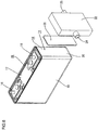
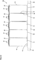
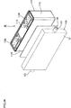
- a cell (electric storage device) 10 according to the embodiment is formed by housing power generating elements (electric storage elements) 12 in a case 11.
- the case 11 includes a plurality of walls to form a flat and approximately cuboid shape.
- the case 11 includes a case body 14 where an opening 13 opening upward is formed, and a lid member 15 assembled to the case body 14 and covering the opening 13 of the case 11.
- the case body 14 is made of metal, and it is possible to use, for the case body 14, arbitrary metal such as aluminum, aluminum alloy and stainless as necessary.
- Two electrode terminals 16 and 16 electrically connected with the power generating elements 12 protrude upward to be formed in places near both left and right ends in Fig. 4 on the lid member 15.
- the electrode terminals 16 are formed of a positive terminal and a negative terminal. Although the details are not illustrated, the positive terminal is electrically connected to a positive plate of the power generating element 12, and the negative plate is electrically connected to a negative plate of the power generating element 12.
- the power generating element 12 is formed by winding the positive and negative plates being laminated via a separator.
- two power generating elements 12 and 12 are housed in one case 11.
- outer surfaces of the case 11 include a terminal surface 17 where the electrode terminals 16 are formed (the top surface in Fig. 2 ), a bottom surface 18 located on an opposite side to the terminal surface 17 (the bottom surface in Fig. 2 ), a long side surface 19 having a relatively large area, and a short side surface 20 having a relatively small area.
- the walls of the case 11 is configured of the terminal surface 17, the bottom surface 18, the long side surface 19 and the short side surface 20.
- the power generating elements 12 are housed in the case 11 in positions where the winding axes are oriented in a direction intersecting with the short side surface 20.
- the two power generating elements 12 and 12 are housed by being arranged in a direction intersecting with the long side surface 19 of the case 11.
- the power generating elements 12 are housed in the case 11 in a position away from the bottom surface 18 and the terminal surface 17 among the inner surfaces of the case 11.
- the power generating elements 12 being away from the inner surface of the case 11 includes a configuration where a buffer material is positioned between the power generating elements 12 and the inner surface of the case 11.
- the case 11 is configured to be filled with an electrolyte (not shown) including an organic solvent.
- an organic solvent it is possible to use, for example, ethylene carbonate, propylene carbonate, buthylene carbonate, dimethyl carbonate, diethyl carbonate, ethyl methyl carbonate, gamma-butyrolactone, gamma-valerolactone, methyl acetate, methyl propionate, tetrahydrofuran, 2-methyltetrahydrofuran, tetrahydropyran, dimethoxyethane, dimethoxymethane, ethylene methyl phosphate, ethyl ethylene phosphate, trimethyl phosphate, and triethyl phosphate. Only one kind may be selected from these organic solvents to be used, or the combination of two or more kinds may be used.
- Cited as a dissolved substance of an electrolyte are an inorganic lithium salt such as LiClO 4 , LiPF 6 , and LiBF 4 , a fluorinated organic lithium salt such as LiCF 3 SO 3 , LiN(CF 3 SO 2 ) 2, LiN (CF 3 CF 2 SO 2 ) 2 , and LiC (CF 3 SO 2 ) 3 , and the like. Only one kind may be selected from these dissolved substances to be used, or the combination of two or more kinds may be used.
- a heat transfer member 21 made of synthetic resin is placed on the bottom surface 18 of the case 11 in contact with the bottom surface 18 of the case 11.
- the heat transfer member 21 can deform elastically, and is formed of synthetic resin with insulation properties.
- the heat transfer member 21 is formed of material having higher thermal conductivity than air. In the embodiment, material having a thermal conductivity of 0.2 W/m ⁇ K to 5.0 W/m ⁇ K is used. It is possible to use, for the heat transfer member 21, an arbitrary synthetic resin, such as polyamide including nylon 66, acrylic resin, silicone resin, polyester resin, or polyolefin resin, as necessary.
- the heat transfer member 21 has a sheet shape having a thickness of 1 mm.
- the heat transfer member 21 is approximately rectangular shaped, and is formed into a shape slightly smaller than the bottom surface 18 of the case 11.
- the thickness of the heat transfer member 21 is set to 1 mm in the embodiment, but is not limited to this, and can be formed into an arbitrary thickness as necessary.
- a cooling member 22 is placed on an undersurface of the heat transfer member 21.
- the undersurface of the heat transfer member 21 is in contact with a top surface of the cooling member 22.
- the cooling member 22 has an approximately cuboid shape and is formed into a shape slightly larger than the heat transfer member 21.
- At least the outer surface of the cooling member 22 is made of metal such as copper, copper alloy, stainless, aluminum, or aluminum alloy. Copper is used in the embodiment.
- a circulation path 23 for circulating a coolant (not shown) is formed in the cooling member 22.
- An inlet port 24 that communicates with the circulation path 23 and through which the coolant flows into the circulation path 23 and an outlet port 25 through which the coolant flows out of the circulation path 23 are formed in the cooling member 22.
- the inlet port 24 or the outlet port 25 is connected to an unillustrated pump via an unillustrated pipe 55, and the coolant circulates in the order of the pipe 55, the inlet port 24, the circulation path 23, the outlet port 25 and the pipe 55.
- a liquid such as water, an organic solvent, or oil is used as a coolant in the embodiment.
- An arbitrary liquid such as water, mineral oil, alkylbenzene, polybutene, alkylnaphthalene, alkyldiphenylethane, silicone oil or ethylene glycol can be used as a coolant as necessary.
- the heat transfer member 21 may be formed of material having viscosity. Moreover, an adhesive layer may be formed on the surface of the heat transfer member 21. Moreover, the heat transfer member 21, the bottom surface 18 of the case 11 and an outer surface of the cooling member 22 may be bonded via the adhesive layer. The above configuration makes it possible to securely bring the heat transfer member 21, the bottom surface 18 of the case 11 and the cooling member 22 into contact with one another.
- the heat transfer member 21 is placed between the bottom surface 18 of the case 11 and the top surface of the cooling member 22 in the cell 10 according to the embodiment.
- the heat transfer member 21 is in contact with the outer surface of the case 11 as well as is in contact with the outer surface of the cooling member 22.
- the heat transfer member 21 can deform elastically and is formed of synthetic resin having higher thermal conductivity than air.
- the power generating element 12 may expand. Consequently, the expanded power generating element 12 presses and expands the case 11.
- the heat transfer member 21 in contact with the outer surface of the case 11 is then pressed by the outer surface of the case 11 while being sandwiched between the outer surface of the case 11 and the outer surface of the cooling member 22. Being able to deform elastically, the heat transfer member 21 deforms elastically by being pressed by the outer surface of the case 11. Accordingly, the outer surface of the case 11 and the outer surface of the heat transfer member 21 are held in contact with each other as well as the outer surface of the heat transfer member 21 and the outer surface of the cooling member 22 are held in contact with each other. As a result, the heat generated in the power generating element 12 upon charge or discharge is transferred from the case 11 to the cooling member 22 through the heat transfer member 21; accordingly, it is possible to inhibit the temperature of the cell 10 from becoming high locally.
- the power generating element 12 contracts upon discharge, and accordingly the case 11, too, contracts.
- the heat transfer member 21 is restored and deformed following the outer surface of the contracted case 11. Accordingly, the outer surface of the case 11 and the outer surface of the heat transfer member 21 are held in contact with each other.
- the outer surface of the case 11, the outer surface of the heat transfer member 21 and the outer surface of the cooling member 22 are held in contact with one another.
- the heat generated in the power generating element 12 upon charge or discharge is securely transferred from the case 11 to the cooling member 22 through the heat transfer member 21, and therefore it is possible to inhibit the temperature of the cell 10 from becoming high locally.
- the cooling member 22 resists deformation by the external pressure. Accordingly, it is possible to inhibit the cooling member 22 from deforming even if the cooling member 22 is pressed via the heat transfer member 21 by the expansion of the case 11. As a result, it is possible to inhibit the circulation path 23 of a coolant from deforming; accordingly, it is possible to inhibit pressure drop from being caused in the coolant circulated in the cooling member 22. Therefore, it is possible to inhibit a decrease in the cooling efficiency of the cooling member 22.
- a liquid is used as a coolant in the embodiment. Accordingly, it is possible to obtain an excellent effect that the cooling efficiency is not dependent on the outdoor temperature compared with what is called air cooling that uses air as a coolant.
- the coolant is set to be a liquid, it is possible to inhibit the entry of a foreign substance into the cooling member 22.
- the case 11 is filled with an electrolyte including an organic solvent in the embodiment.
- an electrolyte includes an organic solvent in this manner, it is feared that if a cell is used at relatively high temperature, gas being a product of the decomposition of the organic solvent evolves. Consequently, it is feared that as the internal pressure of the case 11 increases and the number of charge and discharge cycles increases, the case 11 gradually expands.
- the heat transfer member 21 can deform following the expansion of the case 11. As a result, it is possible to hold the outer surfaces of the case 11, the heat transfer member 21 and the cooling member 22 in contact with one another. Accordingly, even if the number of charge and discharge cycles increases, it is possible to securely inhibit the temperature of the cell 10 from becoming high locally.
- the heat transfer member 21 is in contact with the bottom surface 18 in the embodiment. Having a relatively large area, the long side surface 19 of the case 11 deforms more largely than the bottom surface 18 and the short side surface 20 when the internal pressure of the case 11 increases. Hence, the heat transfer member 21 is brought into contact with the bottom surface 18 that is different from the long side surface 19; accordingly, it is possible to securely hold the outer surface of the case 11 and the heat transfer member 21 in contact with each other.
- a sufficient space for attaching the heat transfer member 21 and the cooling member 22 in a state where the heat transfer member 21 and the cooling member 22 are insulated from the electrode terminals 16 may not be secured on the terminal surface 17 where the electrode terminals 16 are formed. Accordingly, it is feared that if the heat transfer member 21 is attempted to be attached to the terminal surface 17, it is not possible to secure a sufficient contact area between the outer surface of the case 11 and the heat transfer member 21. According to the above embodiment, it is possible to secure a sufficient contact area between the outer surface of the case 11 and the heat transfer member 21 by bringing the heat transfer member 21 into contact with the bottom surface 18.
- the power generating element 12 expands upon charge. Accordingly, it is feared that in an area where the power generating element 12 is in contact with the inner surface of the case 11, the case 11 is pressed and expanded by the expanded power generating element 12.
- the heat transfer member 21 is configured to be in contact with the bottom surface 18 having a relatively large space in between with the power generating element 12 among the wall surfaces of the case 11. Accordingly, the wall surface having a relatively large space in between with the power generating element 12 among the wall surfaces of the case 11 is in contact with the heat transfer member 21. Hence, even if the power generating element 12 expands, the wall surface of the case 11 in contact with the heat transfer member 21 is away from the power generating element 12 and accordingly is inhibited from being pressed by the expanded power generating element 12. As a result, even if the power generating element 12 expands, it is possible to securely hold the outer surface of the case 11 and the heat transfer member 21 in contact with each other.
- the heat transfer member 21 is formed of insulating material. Accordingly, current is inhibited from flowing between the case 11 and the cooling member 22. As a result, current is inhibited from corroding the case 11 or the cooling member 22.
- a heat transfer member 31 is configured to be in contact with the short side surface 20 of the case 11.
- the heat transfer member 31 is approximately rectangular shaped, and is formed into a shape slightly smaller than the short side surface 20 of the case 11.
- a cooling member 32 is placed on a surface of the heat transfer member 31 opposite to the short side surface 20 of the case 11.
- the heat transfer member 31 is in contact with both of the short side surface 20 of the case 11 and the cooling member 32.
- the heat transfer member 31 is in contact with the short side surface 20 that is different from the long side surface 19 having a relatively large area. Accordingly, it is possible to securely hold the outer surface of the case 11 and the heat transfer member 31 in contact with each other.
- the power generating elements 12 are housed in the case 11 in positions where the winding axes are oriented in a direction intersecting with the short side surface 20.
- the power generating element 12 repeats expansion and contraction outward in a direction of the diameter of the winding axis.
- the deformation amount of the power generating element 12 relative to the axis direction is relatively small. Accordingly, in the embodiment, even if the power generating element 12 expands, it is hard for the power generating element 12 to apply a pressing force to the short side surface 20 of the case 11 located outward from the axis direction of the power generating element 12. Since the heat transfer member 31 is in contact with the short side surface 20 of the case 11, even if the power generating element 12 expands, it is possible to securely hold the outer surface of the case 11 and the heat transfer member 31 in contact with each other.
- a heat transfer member 41 is configured to be in contact with the long side surface 19 of the case 11.
- the heat transfer member 41 is approximately rectangular shaped, and is formed into a shape slightly smaller than the long side surface 19 of the case 11 (refer to Fig. 9 ).
- a cooling member 42 is placed on a surface of the heat transfer member 41 opposite to the long side surface 19 of the case 11.
- the heat transfer member 41 is in contact with both of the long side surface 19 of the case 11 and the cooling member 42 (refer to Fig. 10 ).
- the heat transfer member 41 is in contact with the long side surface 19 as well as is in contact with the cooling member 42. Accordingly, the heat generated in the power generating element 12 upon charge or discharge is transferred from the long side surface 19 having a relatively large area to the cooling member 42 through the heat transfer member 41.
- the long side surface 19 of the case 11 is a surface having the largest area in the case 11. Since the long side surface 19 is the surface having the largest area in the case 11, it is possible to cool the power generating element 12 efficiently.
- the long side surface 19 is the surface having the largest area in the case 11 and accordingly is most susceptible to deformation, if the case 11 expands due to an increase in the internal pressure.
- the long side surface 19 is configured to be in contact with the heat transfer member 41 capable of deforming elastically in the embodiment. Hence, even if the long side surface 19 deforms, the heat transfer member 41 deforms elastically to follow the deformation of the long side surface 19. As a result, the long side surface 19 and the heat transfer member 41 are held in contact with each other; accordingly, it is possible to inhibit the temperature of the cell 10 from becoming high locally.
- an assembled battery (electric storage apparatus) 56 is formed by arranging a plurality of cells 10 to be electrically connected.
- the cells 10 are connected in series or in parallel.
- the plurality of cells 10 is fixed in an arranged state by a known method such as a band.
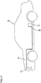
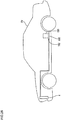
- the assembled battery 56 according to the embodiment is installed on a vehicle 53 such as an electric vehicle or a hybrid vehicle to be used as a power source.
- a radiator 54 is placed in the vehicle 53.
- the radiator 54 and a cooling member 52 are connected by a pipe 55.
- a radiator coolant (not shown) circulates in the radiator 54, the pipe 55, and the cooling member 52.
- An arbitrary liquid such as water, antifreeze including ethylene glycol, or a mixture of water and antifreeze can be used as a radiator coolant as necessary.
- the assembled battery 56 is formed by arranging the plurality of cells 10 in a position that the long side surfaces 19 thereof are opposed to one another.
- the plurality of cells 10 are placed on a top surface of one cooling member 52 via one heat transfer member 51.
- the plurality of cells 10 are configured to be placed on the top surface of one heat transfer member 51 in the embodiment; however, the cells 10 may be configured to be placed on the top surfaces of the heat transfer members 51, respectively.
- an assembled battery 66 is formed by arranging a plurality of cells 10 in a position that the long side surfaces 19 thereof are opposed to one another.
- the plurality of cells 10 are sandwiched between a pair of heat transfer members 61 and 61.
- the heat transfer members 61 are in contact with the short side surfaces 20 of the cells 10.
- Cooling members 62 are placed on surfaces of the heat transfer members 21 opposite to the cells 10, respectively.
- the plurality of cells 10 as a whole is sandwiched between the pair of cooling members 62 and 62 via the pair of heat transfer members 61 and 61.
- LEV50 battery capacity: 50 Ah
- Lithium Energy Japan Lithium Energy Japan
- a battery where a heat transfer member was placed on a bottom surface of a cell and a cooling member was placed on a bottom surface of the heat transfer member was used as a battery 1A.
- 5580H (thickness: 1.0 mm, thermal conductivity: 3W/m ⁇ K) manufactured by Sumitomo 3M Limited was used as a heat transfer member.
- a cooling member made of copper was used. Water was used as a coolant.
- a battery where a heat transfer member was placed on a long side surface of a cell and a cooling member was placed on a surface of the heat transfer member opposite to a case was used as a battery 1B.
- the other configurations were set to be the same as the battery B.
- a battery where neither a heat transfer member nor a cooling member was placed for a cell was used for a comparative example.
- thermocouple attached the long side surface of the case.
- the thermocouple was attached to approximately the center of the long side surface of the case (in proximity to the intersection point of the diagonal lines).
- Charge and discharge of the battery 1A, the battery 1B and the comparative example were carried out in the following conditions.
- the battery 1A, the battery 1B and the comparative example were charged and discharged to the maximum of the rated capacity.
- a constant current was set to 1 CA, a constant voltage to 4.1 V, and a charge time to 4 hours.
- a constant current was set to 1 CA and a cut-off voltage of discharge to 2.75 V. These are set to be one cycle. The above cycle was repeated to measure the temperatures of the outer surfaces of the cases of the battery 1A, the battery 1B and the comparative example at a predetermined number of cycles. The results are shown in Table 1 and Fig. 14 .
- the temperature of the outer surface of the case according to the comparative example increased to as high as 42°C while the temperature of the outer surface of the case of the battery 1A (represented in o in Fig. 14 ) increased only to 39°C and the temperature of the outer surface of the case of the battery 1B (represented in ⁇ in Fig. 14 ) increased only to 40°C.
- the temperature of the outer surface of the case according to the comparative example increased to as high as 51°C while the battery 1A increased only to 41°C and the battery 1B increased only to 45°C.
- the heat transfer member capable of deforming elastically is in contact with the outer surface of the case in the batteries 1A and 1B, the heat transfer member can follow the deformation of the case by deforming elastically even if the case expands with the progress of charge and discharge cycles.
- the outer surface of the case and the heat transfer member can be held in contact with each other; accordingly, heat is efficiently transferred from the outer surface of the case to the heat transfer member.
- the heat generated in the power generating element upon charge and discharge is transferred from the case to the cooling member through the heat transfer member; accordingly, it is possible to inhibit the temperature of the battery from becoming high locally.
- the bottom surface of the case is away from the power generating element housed in the case, it is possible to inhibit the power generating element from pressing the bottom surface of the case even if the power generating element expands with the progress of charge and discharge cycles . Accordingly, the bottom surface of the case is inhibited from expanding, so that the bottom surface of the case is securely in contact with the heat transfer member. As a result, heat is securely transferred from the bottom surface of the case to the heat transfer member; accordingly, it is possible to securely inhibit the temperature of the battery from becoming high locally.
- An assembled battery formed by arranging a plurality of cells is installed on an electric vehicle or the like.
- Circulating cooling air (air) is proposed in JP-A-2000-294302 , for example, in order to cool such an assembled battery.
- battery modules constituting the assembled battery are arranged at intervals as well as a plurality of cells constituting the battery module is arranged at intervals to form a cooling passage.
- the technology disclosed in the specification has been completed based on the above situation, and an object thereof is to provide an electric storage apparatus that is space saving and is superior in cooling performance.
- the technology disclosed in the specification to solve the above problems is an electric storage device including an electric storage element, a case where the electric storage element is housed and electrode terminals are formed to be protruded, and a cooling member placed outside the case for cooling the case.
- the cooling member is placed in direct or indirect contact with a surface other than a surface having the largest area among surfaces of the case except a terminal surface on which the electrode terminals are formed.
- the technology disclosed in the specification is an electric storage apparatus formed by arranging a plurality of the electric storage devices.
- the cooling member Since the cooling member is placed in direct or indirect contact with a surface of the case in the technology disclosed in the specification, unlikely to the configuration where a cooling passage is formed by spacing the electric storage devices, there is no need to widen the spaces to improve the cooling efficiency. Therefore, it is space saving.
- the electric storage devices constituting the electric storage apparatus expand due to the expansion of the electric storage element and an increase in the internal pressure of the battery. Accordingly, if the electric storage devices expand after the cooling member is placed in direct or indirect contact with a surface of the flat square case, for example, and then contact areas of the surface of the case and the cooling member are reduced, the cooling effect by the cooling member cannot be fully obtained. Therefore, the cooling effect for the electric storage devices decreases. Moreover, if the electric storage devices are assembled to the electric storage apparatus, the temperature distribution in the electric storage apparatus may become uneven.
- a surface having the largest area among surfaces of the case of the electric storage device is the most expandable surface when the electric storage device expands; accordingly, it is feared that if the cooling member is placed only on this surface, the contact area with the cooling member becomes smaller and therefore the cooling effect by the cooling member cannot be fully obtained.
- the cooling member is placed in direct or indirect contact with a surface other than the surface having the largest area among the surfaces of the case and accordingly is placed in contact with a surface that resists expansion.
- the cooling member is placed in contact with a surface of the case, the surface resisting expansion; accordingly, it is possible to enlarge the contact area of the cooling member and the surface of the case and fully obtain the cooling effect by the cooling member.
- the cooling member may be a member circulating a coolant to cool the battery case.
- the coolant may be a radiator coolant of a vehicle.
- a radiator coolant of a vehicle.
- the radiator coolant can include antifreeze such as ethylene glycol.
- a thermally conductive member made of material having higher thermal conductivity than air and capable of deforming elastically may be placed between the cooling member and the case.
- the above configuration enables the thermally conductive member to deform following the deformation of the case; accordingly, even if the case deforms due to the long use of the electric storage device, it is possible to maintain the large contact area of the case and the cooling member and therefore it is possible to prevent a decrease in cooling effect.
- the thermally conductive member may have insulating properties.
- the thermally conductive member is made of non-insulated material, there is a concern for safety such as corrosion caused by continuity between the case and the thermally conductive member.
- the case of the electric storage device is made of metal, the above configuration makes it possible to increase safety since there is no continuity between the case and the thermally conductive member.
- the electric storage apparatus may be configured as follows: One cooling member may be provided for two or more electric storage devices. Such a configuration makes it possible to reduce the number of parts and save space.
- the electric storage apparatus may be configured to provide one heat transfer member for two or more electric storage devices. Such a configuration makes it possible to reduce the number of parts and save space.
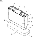
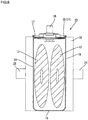
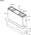
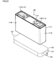
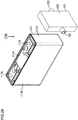
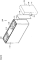
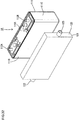
- the cell 110 of the embodiment includes a cuboid (an example of a flat and square shape) battery case (case) 111, a thermally conductive member (heat transfer member) 125 placed beneath the battery case 111, and a cooling member 120.
- a cuboid an example of a flat and square shape
- battery case case
- thermally conductive member heat transfer member
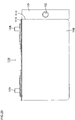
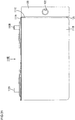
- a top surface 111A of the battery case 111 is a terminal surface 111A formed by protruding a positive terminal 112A and a negative terminal 112B (electrode terminals 112).
- side surfaces 111B and 111C of the battery case 111 are configured of a surface having a large area 111B (also referred to as the "long side surface 111B") and a surface having a small area 111C (also referred to as the "short side surface 111C").
- the cooling member 120 is placed on an undersurface 111D of the battery case 111.
- the undersurface 111D of the case 111 is set to be the bottom surface 111D.
- the terminal surface 111A, the long side surface 111B, the short side surface 111C and the bottom surface 111D constitute a plurality of walls of the battery case 111.
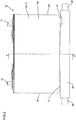
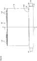
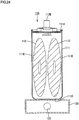
- the battery case 111 is made of metal such as stainless, and houses power generating elements (electric storage elements) 113 therein as shown in Fig. 19 .
- the power generating element 113 is formed by winding a positive plate and a negative plate via a separator.
- two power generating elements 113 and 113 are housed by orienting the winding axes in a direction perpendicular to the short side surface 111C.
- the positive plate is connected to the positive terminal 112A, and the negative plate is connected to the negative terminal 112B.
- a surface having the longest distance apart from the power generating element 113 is the short side surface 111C
- a surface having the shortest distance apart from the power generating element 113 is the long side surface 111B
- a surface having the largest area is the long side surface 111B
- a surface having the smallest area is the short side surface 111C.
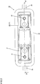
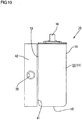
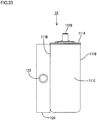
- the cooling member 120 placed beneath the bottom surface 111D of the battery case 111 includes a body portion 121 made of metal for housing an unillustrated coolant therein and circulating the coolant, a coolant inlet port 122 provided at an end portion on the left shown in Fig. 18 of the body portion 121 for introducing the coolant in the body portion 121, and a coolant outlet port 123 provided at an end portion on the right shown in Fig. 18 of the body portion 121 for draining the coolant in the body portion 121 out of the body portion 121.
- a radiator coolant for a vehicle, water, air, or the like can be cited as a coolant to be circulated in the body portion 121 of the cooling member 120.
- Ethylene glycol or the like can be cited as a specific example of a radiator coolant.
- Water and a radiator coolant are preferable among these coolants in the respect that they are not dependent on the outdoor temperature.
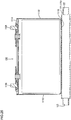
- the sheet-shaped thermally conductive member (heat transfer member) 125 is held between the cooling member 120 and the bottom surface 111D of the battery case 111. Specifically, a top surface of the thermally conductive member 125 is placed in direct contact with the bottom surface 111D of the battery case 111, and an undersurface of the thermally conductive member 125 is placed in direct contact with a top surface of the body portion 121 of the cooling member 120.
- thermally conductive material forming the thermally conductive member 125 is material having higher thermal conductivity than air and capable of deforming elastically following the expansion of the battery.
- the thermally conductive member 125 is made of non-insulated material such as metal, there is a concern for safety such as the corrosion of the battery case 111 caused by continuity between the battery case 111 and the thermally conductive member 125.
- insulating material is preferable as thermally conductive material. Polyamide resin, acrylic resin or the like can be cited as a specific example of such thermally conductive material.
- the cooling member 120 is placed in indirect contact with the bottom surface 111D of the battery case 111 via the thermally conductive material, unlikely to the configuration where a cooling passage is formed by spacing the cells 110, there is no need to widen the spaces to improve the cooling efficiency. Therefore, it is space saving.
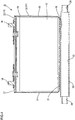
- the short side surface 111C has less influence of the expansion of the power generating element 113.
- the short side surface 111C has the smallest area; accordingly, the cooling efficiency is low.
- the bottom surface 111D of the battery case 111 has a slightly shorter distance apart from the power generating element 113 than the short side surface 111C; however, the bottom surface 111D has a larger area than the short side surface 111C, and has a smaller area than the long side surface 111B.
- the bottom surface 111D resists expansion and cooling efficiency thereof is higher than that of the short side surface 111C. Therefore, in the embodiment, even if the cell 110 itself expands, the cooling member 120 is placed on the surface that resists expansion (bottom surface 111D) among the surfaces of the battery case 111; accordingly, it is possible to enlarge the contact area of the cooling member 120 and the battery case 111. As a result, it is possible to improve the cooling performance of an assembled battery (electric storage apparatus) using the cell 110 of the embodiment.
- the thermally conductive member 125 made of material having higher thermal conductivity than air and capable of deforming elastically is placed between the cooling member 120 and the battery case 111; accordingly, since the thermally conductive member 125 deforms following the deformation of the battery case 111, even if the battery case 111 deforms due to the long use of the cell 110, it is possible to maintain the large contact area of the battery case 111 and the cooling member 120. Therefore it is possible to prevent a decrease in cooling effect.
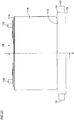
- a cell 130 of Variation 2-1 is different from that of Embodiment 2-1 in the respect that the thermally conductive member 125 is not provided between the battery case 111 and the cooling member 120 .
- the same reference numerals are attached to similar configurations to those in Embodiment 2-1, and the overlapped description will be omitted.
- the cooling member 120 is placed in direct contact with the bottom surface 111D of the battery case 111.
- the configuration other than the above is approximately the same as the cell 110 in Embodiment 2-1 as shown in Figs. 21 to 25 . Therefore, it is possible to provide an assembled battery that is space saving and has improved the cooling performance by the variation, too, similarly to Embodiment 1.
- Embodiment 2-2 A description will be given of an assembled battery 150 of Embodiment 2-2 with reference to Figs. 26 and 27 .
- the assembled battery 150 of the embodiment is installed on the rear of an electric vehicle EV as shown in Fig. 26 .
- the embodiment is different from Embodiment 2-1 in the respects that a plurality of cells 140 is provided and that one cooling member 160 and one thermally conductive member 165 are provided for the plurality of cells 140.
- the same reference numerals are attached to similar configurations to those in Embodiment 2-1, and the overlapped description will be omitted.
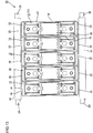
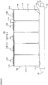
- the assembled battery 150 of the embodiment is formed by arranging a plurality of (five in the embodiment) cells 140 to be opposite to the long side surfaces 111B and 111B.
- the plurality of cells 140 constituting the assembled battery 150 is designed to be electrically connected by connecting an unillustrated conductive member such as a bus bar.
- the cooling member 160 is placed in indirect contact with the bottom surface 111D of the battery case 111 via the sheet-shaped thermally conductive member 165.
- the cooling member 160 includes a body portion 161 made of metal for housing an unillustrated coolant therein and circulating the coolant, a coolant inlet port 162 provided at an end portion on the left shown in Fig. 27 of the body portion 161 for introducing the coolant in the body portion 161, and a coolant outlet port 163 provided at an end portion on the right shown in Fig. 27 of the body portion 161 for draining the coolant in the body portion 161 out of the body portion 161.
- the coolant inlet port 162 and the coolant outlet port 163 are placed on the long side surface 111B sides of the cell 140.
- a coolant circulated in the body portion 161 of the cooling member 160 is a radiator coolant for a vehicle.
- the configuration other than the above is approximately similar to that of Embodiment 2-1.
- the cooling member 160 is placed, via the thermally conductive member 165, in indirect contact with the bottom surface 111D being a surface resisting expansion and having higher cooling efficiency than the short side surface 111C among the surfaces of the battery case 111; accordingly, it is possible to provide the assembled battery 150 that is space saving and where the temperature distribution is even.
- a radiator coolant is used as a coolant, it is possible to use the coolant as a radiator coolant for a vehicle and also for the cooling of the assembled battery 150. Hence, there is no need to separately prepare a coolant for cooling the battery.
- one cooling member 160 is provided for two or more cells 140, and one thermally conductive member 165 is provided for two or more cells 140; accordingly, it is possible to reduce the number of parts and save space.
- a cell 2A (reference numeral 110A in the drawing) was set to be one where the cooling member 120 for one cell was placed in direct contact with the surface having a small area 111C (short side surface 111C) among the side surfaces of the cuboid battery case 111 of a lithium-ion battery (product number: LEV50, battery capacity: 50 Ah) manufactured by Lithium Energy Japan.
- the same reference numerals are attached to similar configurations to those in Embodiment 2-1.
- a cell 2B (reference numeral 110B in the drawing) was obtained in a similar manner to the cell 2A other than a point that the thermally conductive member 125 (a thermally conductive acrylic gel sheet manufactured by Sumitomo 3M Limited, product number: 5580H, thermal conductivity: 3 W/m ⁇ K, thickness: 1.0 mm) was placed between the short side surface 111C of the battery case 111 and the cooling member 120.
- the same reference numerals are attached to the same configurations as those in Embodiment 2-1.
- a cell 2C was obtained in a similar manner to the cell 2A other than a point that the cooling member 120 for one cell was placed in contact with the bottom surface 111D of the battery case 111 (refer to Figs. 21 and 23 ).
- a cell 2D was obtained in a similar manner to the cell 2C other than a point that the thermally conductive member 125 was placed between the bottom surface 111D of the battery case 111 and the cooling member 120 (refer to Figs. 16 and 18 ).
- a cell of Comparative Example 2-1 was set to be a lithium-ion battery (a lithium-ion battery manufactured by Lithium Energy Japan (product number: LEV50)) where the cooling member 120 and the thermally conductive member 125 were not placed.
- LEV50 Lithium Energy Japan
- a cell 1A of Comparative Example 2-2 was set to be one where the cooling member 120 for one cell was placed in direct contact with the surface having a large area 111B (long side surface 111B) among the side surfaces of the cuboid battery case 111 of a lithium-ion battery (product number: LEV50, battery capacity: 50 Ah) manufactured by Lithium Energy Japan.
- the same reference numerals are attached to similar configurations to those in Embodiment 2-1.
- a cell 1B of Comparative Example 2-3 was obtained in a similar manner to the cell 2A other than a point that the thermally conductive member 125 (a thermally conductive acrylic gel sheet manufactured by Sumitomo 3M Limited, product number: 5580H, thermal conductivity: 3 W/m ⁇ K, thickness: 1.0 mm) was placed between the long side surface 111B of the battery case 111 and the cooling member 120 .
- the thermally conductive member 125 a thermally conductive acrylic gel sheet manufactured by Sumitomo 3M Limited, product number: 5580H, thermal conductivity: 3 W/m ⁇ K, thickness: 1.0 mm
- the same reference numerals are attached to similar configurations to those in Embodiment 2-1.
- a cycle test was carried out under an atmosphere of 40°C in the following method for the cells manufactured in 1. (the cells 2A to 2D and the cells of Comparative Examples 2-1 to 2-3) respectively.
- Tap water at 35°C was used as a coolant of the cooling member 120, and was circulated in the body portion 121 of the cooling member 120 at the velocity of 2.5 liter per minute.
- the cells were charged at a constant current (1 CA) and a constant voltage (4.1 V) for four hours, and were discharged at a constant current (1 CA) and a cut-off voltage of discharge of 2.75 V. These were set to one cycle, and charge and discharge were repeated up to 1600 cycles.
- the battery surface temperature of each cell was measured at intervals of 200 cycles and shown in Table 2.
- thermocouple was attached to approximately the center of the long side surface 111B of the battery, and a maximum temperature in one cycle was measured.
- the cell of the present invention makes it possible to fully obtain the cooling effect by the cooling member; accordingly, the cooling performance of an assembled battery can be improved.
- an increase in the battery surface temperature of the cell 2C where only the cooling member was placed on the bottom surface was more gentle than that of the cell 2A where only the cooling member was placed on the short side surface.
- An increase in the battery surface temperature of the cell 2D where the cooling member and the thermally conductive sheet were placed on the bottom surface was more gentle than that of the cell 2B where the cooling member and the thermally conductive sheet were placed on the short side surface.
- the cell 2B having the thermally conductive sheet had a higher effect of inhibiting temperature from increasing after 400 cycles than the cell 2A without the thermally conductive sheet. Also in a comparison between the cells 2C and 2D, the cell 2D having the thermally conductive sheet had a higher effect of inhibiting temperature from increasing after 600 cycles. The results show that even if a battery case deforms due to the long use of a battery, a cell having a thermally conductive member can maintain a large contact area of the battery case and a cooling member, and therefore it is possible to prevent a decrease in cooling effect.
Landscapes
- Chemical & Material Sciences (AREA)
- Chemical Kinetics & Catalysis (AREA)
- Electrochemistry (AREA)
- General Chemical & Material Sciences (AREA)
- Engineering & Computer Science (AREA)
- Manufacturing & Machinery (AREA)
- Physics & Mathematics (AREA)
- Thermal Sciences (AREA)
- Mechanical Engineering (AREA)
- Secondary Cells (AREA)
- Battery Mounting, Suspending (AREA)
Applications Claiming Priority (4)
| Application Number | Priority Date | Filing Date | Title |
|---|---|---|---|
| JP2011002553 | 2011-01-07 | ||
| JP2011002552 | 2011-01-07 | ||
| JP2011266933A JP5804323B2 (ja) | 2011-01-07 | 2011-12-06 | 蓄電素子及び蓄電装置 |
| EP12150302.3A EP2475025B1 (en) | 2011-01-07 | 2012-01-05 | Electric storage device and electric storage apparatus |
Related Parent Applications (2)
| Application Number | Title | Priority Date | Filing Date |
|---|---|---|---|
| EP12150302.3A Division-Into EP2475025B1 (en) | 2011-01-07 | 2012-01-05 | Electric storage device and electric storage apparatus |
| EP12150302.3A Division EP2475025B1 (en) | 2011-01-07 | 2012-01-05 | Electric storage device and electric storage apparatus |
Publications (2)
| Publication Number | Publication Date |
|---|---|
| EP3312032A1 EP3312032A1 (en) | 2018-04-25 |
| EP3312032B1 true EP3312032B1 (en) | 2019-03-27 |
Family
ID=45444549
Family Applications (2)
| Application Number | Title | Priority Date | Filing Date |
|---|---|---|---|
| EP12150302.3A Active EP2475025B1 (en) | 2011-01-07 | 2012-01-05 | Electric storage device and electric storage apparatus |
| EP17205195.5A Active EP3312032B1 (en) | 2011-01-07 | 2012-01-05 | Electric storage apparatus |
Family Applications Before (1)
| Application Number | Title | Priority Date | Filing Date |
|---|---|---|---|
| EP12150302.3A Active EP2475025B1 (en) | 2011-01-07 | 2012-01-05 | Electric storage device and electric storage apparatus |
Country Status (6)
| Country | Link |
|---|---|
| US (4) | US8846226B2 (zh) |
| EP (2) | EP2475025B1 (zh) |
| JP (1) | JP5804323B2 (zh) |
| KR (1) | KR101736886B1 (zh) |
| CN (2) | CN102593549B (zh) |
| DE (2) | DE202012013315U1 (zh) |
Families Citing this family (47)
| Publication number | Priority date | Publication date | Assignee | Title |
|---|---|---|---|---|
| JP5804323B2 (ja) | 2011-01-07 | 2015-11-04 | 株式会社Gsユアサ | 蓄電素子及び蓄電装置 |
| US8859128B2 (en) * | 2012-04-30 | 2014-10-14 | Robert Bosch Gmbh | Enhanced thermal contact |
| DE102012218991A1 (de) * | 2012-10-18 | 2014-06-12 | Bayerische Motoren Werke Aktiengesellschaft | Energiespeicherzelle und Energiespeichermodul |
| JP6144522B2 (ja) | 2013-04-01 | 2017-06-07 | カルソニックカンセイ株式会社 | 温調装置 |
| JP6174381B2 (ja) * | 2013-06-06 | 2017-08-02 | 日立オートモティブシステムズ株式会社 | 蓄電ブロックおよび蓄電モジュール |
| US10153526B2 (en) * | 2013-07-17 | 2018-12-11 | Calsonic Kansei Corporation | Assembled battery |
| TWI489674B (zh) * | 2014-01-13 | 2015-06-21 | 新普科技股份有限公司 | 散熱件及其組成之電池模組 |
| JP6492400B2 (ja) * | 2014-01-31 | 2019-04-03 | 株式会社Gsユアサ | 蓄電素子及び蓄電モジュール |
| DE102014203846A1 (de) * | 2014-03-03 | 2015-09-03 | MAHLE Behr GmbH & Co. KG | Anordnung mit einer elektrischen Komponente und einem Wärmetauscher |
| FR3019688B1 (fr) * | 2014-04-03 | 2016-05-06 | Renault Sa | "batterie de vehicule automobile equipee d'une conduite de fluide caloporteur separee des elements de batterie par une cloison souple" |
| DE102014209273A1 (de) * | 2014-05-16 | 2015-11-19 | Bayerische Motoren Werke Aktiengesellschaft | Verbindung zwischen zwei Batteriemodulen eines Batteriesystems |
| DE102015202173B4 (de) * | 2015-02-06 | 2017-06-01 | Bayerische Motoren Werke Aktiengesellschaft | Anschlusseinrichtung für einen Energiespeicher an ein kraftfahrzeuginternes Kühlsystem |
| JP2018060594A (ja) * | 2015-02-25 | 2018-04-12 | パナソニックIpマネジメント株式会社 | 電池モジュール |
| CN107710493B (zh) * | 2015-07-20 | 2020-04-17 | 微宏动力系统(湖州)有限公司 | 电池组及电池组系统 |
| DE102015115602A1 (de) | 2015-09-16 | 2017-03-16 | Dr. Ing. H.C. F. Porsche Aktiengesellschaft | Batteriezelle für die Traktionsbatterie eines elektrisch betriebenen Fahrzeugs und entsprechendes Herstellungsverfahren |
| US11296370B2 (en) * | 2015-12-03 | 2022-04-05 | Eaglepicher Technologies, Llc | Battery having high thermal conductivity case |
| JP6387362B2 (ja) * | 2016-01-29 | 2018-09-05 | 本田技研工業株式会社 | コンデンサユニット |
| KR102173142B1 (ko) * | 2016-02-12 | 2020-11-02 | 주식회사 엘지화학 | 배터리 모듈 및 이를 포함하는 배터리 팩 |
| EP3220444A1 (de) * | 2016-03-14 | 2017-09-20 | Nordfels GmbH | Batterie |
| KR102130818B1 (ko) | 2016-09-28 | 2020-07-06 | 주식회사 엘지화학 | 냉각 유로를 구비한 배터리 모듈 및 그 조립방법과 프레임 어셈블리 |
| DE102016118864A1 (de) | 2016-10-05 | 2018-04-05 | Johnson Controls Advanced Power Solutions Gmbh | Energiespeichermodul mit einem Temperaturmanagement-System und ein Energiespeichersystem |
| KR20180069989A (ko) * | 2016-12-15 | 2018-06-26 | 현대자동차주식회사 | 냉각 구조가 구비된 배터리 모듈 |
| CN111247686A (zh) * | 2017-09-22 | 2020-06-05 | 株式会社杰士汤浅国际 | 蓄电装置 |
| KR20190051300A (ko) | 2017-11-06 | 2019-05-15 | 주식회사 엘지화학 | 배터리의 냉각 플레이트 부착 방법 및 이를 통해 제작된 배터리 팩 |
| KR102518184B1 (ko) * | 2017-11-21 | 2023-04-07 | 현대자동차주식회사 | 차량용 고전압배터리의 냉난방시스템 |
| JP7170457B2 (ja) * | 2017-12-27 | 2022-11-14 | 昭和電工株式会社 | 組電池装置 |
| USD877063S1 (en) * | 2018-01-03 | 2020-03-03 | Merry Electronics (Shenzhen) Co., Ltd. | Power expansion accessory |
| JP7010007B2 (ja) * | 2018-01-12 | 2022-02-10 | トヨタ自動車株式会社 | 組電池の製造方法 |
| GB2570300B (en) * | 2018-01-17 | 2020-11-25 | Siemens Ag | Energy storage system |
| KR20190102755A (ko) | 2018-02-27 | 2019-09-04 | 안준배 | 권리 소멸 특허 활용 플랫폼 및 방법 |
| EP3584877A1 (en) | 2018-05-16 | 2019-12-25 | Samsung SDI Co., Ltd. | Battery pack comprising a frame profile with integral coolant circuit elements |
| JP6931626B2 (ja) * | 2018-06-05 | 2021-09-08 | 株式会社Subaru | 車両用電池の冷却構造 |
| CN108520932A (zh) * | 2018-06-14 | 2018-09-11 | 北京科易动力科技有限公司 | 电池包及具有其的车辆 |
| DE102018213546A1 (de) * | 2018-08-10 | 2020-02-13 | Audi Ag | Hochvoltbatterie für ein Kraftfahrzeug und Kraftfahrzeug |
| CN108923008B (zh) * | 2018-08-21 | 2024-08-20 | 广东亿鑫丰智能装备股份有限公司 | 一种改进型液冷电池箱 |
| DE102018214543A1 (de) * | 2018-08-28 | 2020-03-05 | Audi Ag | Batteriezelle mit integrierter Kühlung und Batteriemodul für ein Kraftfahrzeug mit mehreren Batteriezellen |
| DE102018216075A1 (de) * | 2018-09-20 | 2020-03-26 | Bayerische Motoren Werke Aktiengesellschaft | Speicherzelle zum elektrochemischen Speichern von elektrischer Energie, insbesondere für ein Kraftfahrzeug, Energiespeicher zum elektrochemischen Speichern von elektrischer Energie für ein Kraftfahrzeug, Kraftfahrzeug und Verfahren zum Herstellen einer solchen Speicherzelle |
| GB2578738B (en) * | 2018-11-05 | 2020-12-09 | Xerotech Ltd | Thermal management system for a battery |
| JP7074085B2 (ja) * | 2019-01-23 | 2022-05-24 | トヨタ自動車株式会社 | 電池装置 |
| KR20210011639A (ko) * | 2019-07-23 | 2021-02-02 | 에스케이이노베이션 주식회사 | 이차전지 및 이를 포함하는 배터리 모듈 |
| US11646461B2 (en) * | 2020-03-17 | 2023-05-09 | The Boeing Company | Battery cooling systems and methods |
| US11799150B2 (en) * | 2020-07-17 | 2023-10-24 | Toyota Motor Engineering & Manufacturing North America, Inc. | Cooling structure for hybrid-electric vehicle battery cell assemblies |
| WO2022074282A1 (en) | 2020-10-05 | 2022-04-14 | Turun Ammattikorkeakoulu Oy | Battery lid and battery assembly |
| JP7111237B1 (ja) | 2021-10-14 | 2022-08-02 | 大日本印刷株式会社 | 放熱シートを用いた蓄電デバイスモジュール、電動モビリティ |
| CN118451590A (zh) * | 2021-12-27 | 2024-08-06 | 日产自动车株式会社 | 导热构件 |
| KR20240117127A (ko) * | 2022-02-21 | 2024-07-31 | 컨템포러리 엠퍼렉스 테크놀로지 씨오., 리미티드 | 전지 및 전기 장치 |
| US20240128532A1 (en) * | 2022-10-14 | 2024-04-18 | Rivian Ip Holdings, Llc | Structural side thermal components |
Family Cites Families (46)
| Publication number | Priority date | Publication date | Assignee | Title |
|---|---|---|---|---|
| JP3451142B2 (ja) * | 1994-11-18 | 2003-09-29 | 本田技研工業株式会社 | 温度制御機構を備えたバッテリ組立体 |
| JPH09199093A (ja) | 1996-01-17 | 1997-07-31 | Matsushita Electric Ind Co Ltd | 蓄電池用電槽および蓄電池 |
| US5756229A (en) * | 1996-12-17 | 1998-05-26 | Wilson Greatbatch Ltd. | Electrochemical cell having mechanical shock tolerance |
| US6087036A (en) * | 1997-07-25 | 2000-07-11 | 3M Innovative Properties Company | Thermal management system and method for a solid-state energy storing device |
| JP4355865B2 (ja) * | 1998-11-10 | 2009-11-04 | 株式会社ジーエス・ユアサコーポレーション | 電池 |
| JP2000294302A (ja) | 1999-04-08 | 2000-10-20 | Japan Storage Battery Co Ltd | 蓄電池ユニット |
| JP2000348781A (ja) | 1999-06-04 | 2000-12-15 | Japan Storage Battery Co Ltd | 非水電解質電池 |
| JP4826686B2 (ja) * | 2001-01-29 | 2011-11-30 | 株式会社Gsユアサ | 組電池 |
| JP4096162B2 (ja) | 2002-05-28 | 2008-06-04 | 株式会社ジーエス・ユアサコーポレーション | 電池 |
| JP2004303500A (ja) * | 2003-03-31 | 2004-10-28 | Sanyo Electric Co Ltd | 角形電池 |
| KR100599709B1 (ko) | 2004-07-28 | 2006-07-12 | 삼성에스디아이 주식회사 | 이차 전지 |
| FR2883665B1 (fr) | 2005-03-25 | 2007-06-15 | Valeo Equip Electr Moteur | Dispositif d'alimentation electrique pour vehicule automobile |
| RU2008114327A (ru) * | 2005-09-13 | 2009-10-20 | Валео Экипман Электрик Мотер (Fr) | Компактное устройство электрического питания для автотранспортного средства |
| KR100671648B1 (ko) | 2005-12-08 | 2007-01-19 | 삼성에스디아이 주식회사 | 데이터 구동부 및 이를 이용한 유기 발광 표시장치와 그의구동방법 |
| KR100942986B1 (ko) * | 2006-03-21 | 2010-02-17 | 주식회사 엘지화학 | 전지셀 사이에 접착부재가 부착되어 있는 전지모듈 |
| JP4997819B2 (ja) * | 2006-04-28 | 2012-08-08 | トヨタ自動車株式会社 | 電池モジュール |
| JP4857896B2 (ja) * | 2006-05-11 | 2012-01-18 | トヨタ自動車株式会社 | 組電池および車両 |
| JP5061502B2 (ja) * | 2006-05-20 | 2012-10-31 | 日産自動車株式会社 | 電池構造体 |
| JP2008016250A (ja) | 2006-07-04 | 2008-01-24 | Toyota Motor Corp | 電池及び電池の製造方法 |
| JP4501080B2 (ja) * | 2006-10-23 | 2010-07-14 | トヨタ自動車株式会社 | 組電池およびその製造方法 |
| JP2008108651A (ja) * | 2006-10-27 | 2008-05-08 | Toyota Motor Corp | 組電池およびその製造方法 |
| JP4906538B2 (ja) * | 2007-02-28 | 2012-03-28 | 日立ビークルエナジー株式会社 | リチウム二次電池 |
| JP4396716B2 (ja) | 2007-03-02 | 2010-01-13 | トヨタ自動車株式会社 | 温度調節機構および車両 |
| JP4442628B2 (ja) | 2007-03-30 | 2010-03-31 | トヨタ自動車株式会社 | 電源装置及び車両 |
| JP2009004237A (ja) | 2007-06-21 | 2009-01-08 | Toyota Motor Corp | 蓄電装置及び車両 |
| JP5142605B2 (ja) * | 2007-06-28 | 2013-02-13 | 三洋電機株式会社 | 車両用の電源装置 |
| JP2009110832A (ja) | 2007-10-31 | 2009-05-21 | Sanyo Electric Co Ltd | 角形電池及び電池パック |
| JP2009146645A (ja) | 2007-12-12 | 2009-07-02 | Toyota Motor Corp | 溶接構造体の製造方法及び電池の製造方法 |
| JP4587055B2 (ja) | 2008-03-06 | 2010-11-24 | トヨタ自動車株式会社 | 組電池 |
| JP5433160B2 (ja) | 2008-04-04 | 2014-03-05 | 株式会社Uacj | 電気化学デバイスユニットモジュール |
| FR2935995B1 (fr) | 2008-09-18 | 2011-07-22 | Arjowiggins Security | Procede de fabrication d'un jet a base de matiere fibreuse utilisant une bande disposee dans une cuve et document comportant un tel jet. |
| JP5481827B2 (ja) | 2008-10-15 | 2014-04-23 | 株式会社Gsユアサ | 電池 |
| DE102008059954B4 (de) * | 2008-12-02 | 2013-11-07 | Daimler Ag | Batterie mit mehreren parallel und/oder seriell miteinander elektrisch verschalteten Batteriezellen und einer Kühlvorrichtung und die Verwendung der Batterie |
| JP5646812B2 (ja) | 2008-12-15 | 2014-12-24 | スリーエム イノベイティブ プロパティズ カンパニー | アクリル系熱伝導性シートおよびその製造方法 |
| DE102009000066A1 (de) | 2009-01-08 | 2010-07-15 | Robert Bosch Gmbh | Kühlung von Batteriezellen |
| JP2010186715A (ja) * | 2009-02-13 | 2010-08-26 | Mitsubishi Heavy Ind Ltd | 組電池の放熱構造及び組電池 |
| JP2010192207A (ja) * | 2009-02-17 | 2010-09-02 | Mitsubishi Heavy Ind Ltd | 電池用冷却装置及び組電池 |
| US8697275B2 (en) * | 2009-03-04 | 2014-04-15 | Samsung Sdi Co., Ltd. | Rechargeable battery having an extendable case region |
| JP2010244978A (ja) | 2009-04-09 | 2010-10-28 | Toyota Motor Corp | 熱交換媒体および蓄電装置 |
| JP5456371B2 (ja) * | 2009-05-28 | 2014-03-26 | 三洋電機株式会社 | 車両用のバッテリシステム及びこのバッテリシステムを搭載する車両 |
| JP5584433B2 (ja) | 2009-06-17 | 2014-09-03 | 株式会社ジャパンディスプレイ | 液晶表示装置 |
| JP5418007B2 (ja) | 2009-06-17 | 2014-02-19 | 富士ゼロックス株式会社 | 光定着用カラートナー、静電荷像現像剤、現像剤カートリッジ、及びカラー画像形成装置 |
| KR101093890B1 (ko) * | 2010-01-12 | 2011-12-13 | 삼성에스디아이 주식회사 | 이차전지 |
| DE102010041285A1 (de) * | 2010-09-23 | 2012-03-29 | Sb Limotive Company Ltd. | Batterie mit verbesserter Wärmeabfuhr durch Nutzung des Kapillareffekts |
| US9343772B2 (en) * | 2010-10-08 | 2016-05-17 | Samsung Sdi Co., Ltd. | Rechargeable battery |
| JP5804323B2 (ja) * | 2011-01-07 | 2015-11-04 | 株式会社Gsユアサ | 蓄電素子及び蓄電装置 |
-
2011
- 2011-12-06 JP JP2011266933A patent/JP5804323B2/ja active Active
-
2012
- 2012-01-05 US US13/344,453 patent/US8846226B2/en active Active
- 2012-01-05 EP EP12150302.3A patent/EP2475025B1/en active Active
- 2012-01-05 DE DE202012013315.2U patent/DE202012013315U1/de not_active Expired - Lifetime
- 2012-01-05 EP EP17205195.5A patent/EP3312032B1/en active Active
- 2012-01-05 DE DE202012013288.1U patent/DE202012013288U1/de not_active Expired - Lifetime
- 2012-01-06 KR KR1020120001767A patent/KR101736886B1/ko active IP Right Grant
- 2012-01-06 CN CN201210003942.6A patent/CN102593549B/zh active Active
- 2012-01-06 CN CN201510738725.5A patent/CN105406151B/zh active Active
-
2014
- 2014-08-26 US US14/469,328 patent/US9509022B2/en active Active
-
2016
- 2016-10-20 US US15/298,788 patent/US10122053B2/en active Active
-
2018
- 2018-10-19 US US16/165,648 patent/US20190058228A1/en not_active Abandoned
Also Published As
| Publication number | Publication date |
|---|---|
| EP2475025A1 (en) | 2012-07-11 |
| JP2012156124A (ja) | 2012-08-16 |
| US20170040652A1 (en) | 2017-02-09 |
| EP2475025B1 (en) | 2018-03-14 |
| US8846226B2 (en) | 2014-09-30 |
| US20190058228A1 (en) | 2019-02-21 |
| US20140363709A1 (en) | 2014-12-11 |
| CN105406151A (zh) | 2016-03-16 |
| KR20120080543A (ko) | 2012-07-17 |
| US10122053B2 (en) | 2018-11-06 |
| JP5804323B2 (ja) | 2015-11-04 |
| DE202012013288U1 (de) | 2016-01-18 |
| KR101736886B1 (ko) | 2017-05-17 |
| CN105406151B (zh) | 2018-06-22 |
| US9509022B2 (en) | 2016-11-29 |
| CN102593549B (zh) | 2015-12-09 |
| DE202012013315U1 (de) | 2016-06-24 |
| CN102593549A (zh) | 2012-07-18 |
| EP3312032A1 (en) | 2018-04-25 |
| US20120177960A1 (en) | 2012-07-12 |
Similar Documents
| Publication | Publication Date | Title |
|---|---|---|
| EP3312032B1 (en) | Electric storage apparatus | |
| JP6020942B2 (ja) | 蓄電装置 | |
| EP2337112B1 (en) | Battery pack and vehicle including the battery pack | |
| US11870046B2 (en) | Battery pack | |
| US10632848B2 (en) | Battery module of improved safety | |
| KR101990590B1 (ko) | 배터리 모듈, 배터리 모듈을 포함하는 배터리 팩 및 배터리 팩을 포함하는 자동차 | |
| US9673495B2 (en) | Battery module assembly having coolant flow channel | |
| US10283822B2 (en) | Battery module assembly | |
| US9219261B2 (en) | Battery pack | |
| US20150064540A1 (en) | Battery module having structure of improved stability and high cooling efficiency | |
| KR101496523B1 (ko) | 배터리 셀의 방열판 | |
| KR20190001410A (ko) | 배터리 모듈 | |
| KR20180045838A (ko) | 전지시스템 및 전지시스템과 전기자동차를 위한 베이스플레이트 | |
| CN115152081A (zh) | 电池组及包括其的装置 | |
| CN112350011A (zh) | 电池模块 | |
| EP3772122B1 (en) | Battery module with a multifunctional end-plate | |
| US10886582B2 (en) | Cooling fin spacer | |
| KR20180081235A (ko) | 냉각 효율성이 향상된 전지셀 | |
| US20230268583A1 (en) | Battery | |
| KR20220013633A (ko) | 이차전지 및 이를 포함하는 배터리 모듈 |
Legal Events
| Date | Code | Title | Description |
|---|---|---|---|
| PUAI | Public reference made under article 153(3) epc to a published international application that has entered the european phase |
Free format text: ORIGINAL CODE: 0009012 |
|
| STAA | Information on the status of an ep patent application or granted ep patent |
Free format text: STATUS: THE APPLICATION HAS BEEN PUBLISHED |
|
| AC | Divisional application: reference to earlier application |
Ref document number: 2475025 Country of ref document: EP Kind code of ref document: P |
|
| AK | Designated contracting states |
Kind code of ref document: A1 Designated state(s): AL AT BE BG CH CY CZ DE DK EE ES FI FR GB GR HR HU IE IS IT LI LT LU LV MC MK MT NL NO PL PT RO RS SE SI SK SM TR |
|
| STAA | Information on the status of an ep patent application or granted ep patent |
Free format text: STATUS: REQUEST FOR EXAMINATION WAS MADE |
|
| 17P | Request for examination filed |
Effective date: 20180629 |
|
| RBV | Designated contracting states (corrected) |
Designated state(s): AL AT BE BG CH CY CZ DE DK EE ES FI FR GB GR HR HU IE IS IT LI LT LU LV MC MK MT NL NO PL PT RO RS SE SI SK SM TR |
|
| GRAP | Despatch of communication of intention to grant a patent |
Free format text: ORIGINAL CODE: EPIDOSNIGR1 |
|
| STAA | Information on the status of an ep patent application or granted ep patent |
Free format text: STATUS: GRANT OF PATENT IS INTENDED |
|
| RIC1 | Information provided on ipc code assigned before grant |
Ipc: H01M 10/6556 20140101ALI20180920BHEP Ipc: H01M 10/64 20140101ALI20180920BHEP Ipc: H01M 10/6551 20140101ALI20180920BHEP Ipc: H01M 10/625 20140101ALI20180920BHEP Ipc: H01M 10/643 20140101ALI20180920BHEP Ipc: B60H 1/00 20060101AFI20180920BHEP Ipc: H01M 2/02 20060101ALN20180920BHEP Ipc: H01M 10/653 20140101ALI20180920BHEP Ipc: H01M 2/10 20060101ALI20180920BHEP Ipc: H01M 10/6567 20140101ALI20180920BHEP Ipc: H01M 10/613 20140101ALI20180920BHEP Ipc: H01M 10/647 20140101ALI20180920BHEP Ipc: H01M 10/6554 20140101ALI20180920BHEP Ipc: H01M 10/6568 20140101ALI20180920BHEP |
|
| INTG | Intention to grant announced |
Effective date: 20181008 |
|
| GRAS | Grant fee paid |
Free format text: ORIGINAL CODE: EPIDOSNIGR3 |
|
| GRAA | (expected) grant |
Free format text: ORIGINAL CODE: 0009210 |
|
| STAA | Information on the status of an ep patent application or granted ep patent |
Free format text: STATUS: THE PATENT HAS BEEN GRANTED |
|
| AC | Divisional application: reference to earlier application |
Ref document number: 2475025 Country of ref document: EP Kind code of ref document: P |
|
| AK | Designated contracting states |
Kind code of ref document: B1 Designated state(s): AL AT BE BG CH CY CZ DE DK EE ES FI FR GB GR HR HU IE IS IT LI LT LU LV MC MK MT NL NO PL PT RO RS SE SI SK SM TR |
|
| REG | Reference to a national code |
Ref country code: GB Ref legal event code: FG4D |
|
| REG | Reference to a national code |
Ref country code: CH Ref legal event code: EP |
|
| REG | Reference to a national code |
Ref country code: AT Ref legal event code: REF Ref document number: 1112619 Country of ref document: AT Kind code of ref document: T Effective date: 20190415 |
|
| REG | Reference to a national code |
Ref country code: IE Ref legal event code: FG4D |
|
| REG | Reference to a national code |
Ref country code: DE Ref legal event code: R096 Ref document number: 602012058460 Country of ref document: DE |
|
| PG25 | Lapsed in a contracting state [announced via postgrant information from national office to epo] |
Ref country code: FI Free format text: LAPSE BECAUSE OF FAILURE TO SUBMIT A TRANSLATION OF THE DESCRIPTION OR TO PAY THE FEE WITHIN THE PRESCRIBED TIME-LIMIT Effective date: 20190327 Ref country code: LT Free format text: LAPSE BECAUSE OF FAILURE TO SUBMIT A TRANSLATION OF THE DESCRIPTION OR TO PAY THE FEE WITHIN THE PRESCRIBED TIME-LIMIT Effective date: 20190327 Ref country code: SE Free format text: LAPSE BECAUSE OF FAILURE TO SUBMIT A TRANSLATION OF THE DESCRIPTION OR TO PAY THE FEE WITHIN THE PRESCRIBED TIME-LIMIT Effective date: 20190327 Ref country code: NO Free format text: LAPSE BECAUSE OF FAILURE TO SUBMIT A TRANSLATION OF THE DESCRIPTION OR TO PAY THE FEE WITHIN THE PRESCRIBED TIME-LIMIT Effective date: 20190627 |
|
| REG | Reference to a national code |
Ref country code: NL Ref legal event code: MP Effective date: 20190327 |
|
| PG25 | Lapsed in a contracting state [announced via postgrant information from national office to epo] |
Ref country code: GR Free format text: LAPSE BECAUSE OF FAILURE TO SUBMIT A TRANSLATION OF THE DESCRIPTION OR TO PAY THE FEE WITHIN THE PRESCRIBED TIME-LIMIT Effective date: 20190628 Ref country code: HR Free format text: LAPSE BECAUSE OF FAILURE TO SUBMIT A TRANSLATION OF THE DESCRIPTION OR TO PAY THE FEE WITHIN THE PRESCRIBED TIME-LIMIT Effective date: 20190327 Ref country code: NL Free format text: LAPSE BECAUSE OF FAILURE TO SUBMIT A TRANSLATION OF THE DESCRIPTION OR TO PAY THE FEE WITHIN THE PRESCRIBED TIME-LIMIT Effective date: 20190327 Ref country code: BG Free format text: LAPSE BECAUSE OF FAILURE TO SUBMIT A TRANSLATION OF THE DESCRIPTION OR TO PAY THE FEE WITHIN THE PRESCRIBED TIME-LIMIT Effective date: 20190627 Ref country code: LV Free format text: LAPSE BECAUSE OF FAILURE TO SUBMIT A TRANSLATION OF THE DESCRIPTION OR TO PAY THE FEE WITHIN THE PRESCRIBED TIME-LIMIT Effective date: 20190327 Ref country code: RS Free format text: LAPSE BECAUSE OF FAILURE TO SUBMIT A TRANSLATION OF THE DESCRIPTION OR TO PAY THE FEE WITHIN THE PRESCRIBED TIME-LIMIT Effective date: 20190327 |
|
| REG | Reference to a national code |
Ref country code: AT Ref legal event code: MK05 Ref document number: 1112619 Country of ref document: AT Kind code of ref document: T Effective date: 20190327 |
|
| PG25 | Lapsed in a contracting state [announced via postgrant information from national office to epo] |
Ref country code: AL Free format text: LAPSE BECAUSE OF FAILURE TO SUBMIT A TRANSLATION OF THE DESCRIPTION OR TO PAY THE FEE WITHIN THE PRESCRIBED TIME-LIMIT Effective date: 20190327 Ref country code: PT Free format text: LAPSE BECAUSE OF FAILURE TO SUBMIT A TRANSLATION OF THE DESCRIPTION OR TO PAY THE FEE WITHIN THE PRESCRIBED TIME-LIMIT Effective date: 20190727 Ref country code: EE Free format text: LAPSE BECAUSE OF FAILURE TO SUBMIT A TRANSLATION OF THE DESCRIPTION OR TO PAY THE FEE WITHIN THE PRESCRIBED TIME-LIMIT Effective date: 20190327 Ref country code: SK Free format text: LAPSE BECAUSE OF FAILURE TO SUBMIT A TRANSLATION OF THE DESCRIPTION OR TO PAY THE FEE WITHIN THE PRESCRIBED TIME-LIMIT Effective date: 20190327 Ref country code: RO Free format text: LAPSE BECAUSE OF FAILURE TO SUBMIT A TRANSLATION OF THE DESCRIPTION OR TO PAY THE FEE WITHIN THE PRESCRIBED TIME-LIMIT Effective date: 20190327 Ref country code: IT Free format text: LAPSE BECAUSE OF FAILURE TO SUBMIT A TRANSLATION OF THE DESCRIPTION OR TO PAY THE FEE WITHIN THE PRESCRIBED TIME-LIMIT Effective date: 20190327 Ref country code: CZ Free format text: LAPSE BECAUSE OF FAILURE TO SUBMIT A TRANSLATION OF THE DESCRIPTION OR TO PAY THE FEE WITHIN THE PRESCRIBED TIME-LIMIT Effective date: 20190327 Ref country code: ES Free format text: LAPSE BECAUSE OF FAILURE TO SUBMIT A TRANSLATION OF THE DESCRIPTION OR TO PAY THE FEE WITHIN THE PRESCRIBED TIME-LIMIT Effective date: 20190327 |
|
| PG25 | Lapsed in a contracting state [announced via postgrant information from national office to epo] |
Ref country code: PL Free format text: LAPSE BECAUSE OF FAILURE TO SUBMIT A TRANSLATION OF THE DESCRIPTION OR TO PAY THE FEE WITHIN THE PRESCRIBED TIME-LIMIT Effective date: 20190327 Ref country code: SM Free format text: LAPSE BECAUSE OF FAILURE TO SUBMIT A TRANSLATION OF THE DESCRIPTION OR TO PAY THE FEE WITHIN THE PRESCRIBED TIME-LIMIT Effective date: 20190327 |
|
| PG25 | Lapsed in a contracting state [announced via postgrant information from national office to epo] |
Ref country code: IS Free format text: LAPSE BECAUSE OF FAILURE TO SUBMIT A TRANSLATION OF THE DESCRIPTION OR TO PAY THE FEE WITHIN THE PRESCRIBED TIME-LIMIT Effective date: 20190727 Ref country code: AT Free format text: LAPSE BECAUSE OF FAILURE TO SUBMIT A TRANSLATION OF THE DESCRIPTION OR TO PAY THE FEE WITHIN THE PRESCRIBED TIME-LIMIT Effective date: 20190327 |
|
| REG | Reference to a national code |
Ref country code: DE Ref legal event code: R097 Ref document number: 602012058460 Country of ref document: DE |
|
| PG25 | Lapsed in a contracting state [announced via postgrant information from national office to epo] |
Ref country code: DK Free format text: LAPSE BECAUSE OF FAILURE TO SUBMIT A TRANSLATION OF THE DESCRIPTION OR TO PAY THE FEE WITHIN THE PRESCRIBED TIME-LIMIT Effective date: 20190327 |
|
| PLBE | No opposition filed within time limit |
Free format text: ORIGINAL CODE: 0009261 |
|
| STAA | Information on the status of an ep patent application or granted ep patent |
Free format text: STATUS: NO OPPOSITION FILED WITHIN TIME LIMIT |
|
| 26N | No opposition filed |
Effective date: 20200103 |
|
| PG25 | Lapsed in a contracting state [announced via postgrant information from national office to epo] |
Ref country code: TR Free format text: LAPSE BECAUSE OF FAILURE TO SUBMIT A TRANSLATION OF THE DESCRIPTION OR TO PAY THE FEE WITHIN THE PRESCRIBED TIME-LIMIT Effective date: 20190327 |
|
| PG25 | Lapsed in a contracting state [announced via postgrant information from national office to epo] |
Ref country code: MC Free format text: LAPSE BECAUSE OF FAILURE TO SUBMIT A TRANSLATION OF THE DESCRIPTION OR TO PAY THE FEE WITHIN THE PRESCRIBED TIME-LIMIT Effective date: 20190327 |
|
| REG | Reference to a national code |
Ref country code: CH Ref legal event code: PL |
|
| REG | Reference to a national code |
Ref country code: BE Ref legal event code: MM Effective date: 20200131 |
|
| PG25 | Lapsed in a contracting state [announced via postgrant information from national office to epo] |
Ref country code: LU Free format text: LAPSE BECAUSE OF NON-PAYMENT OF DUE FEES Effective date: 20200105 |
|
| PG25 | Lapsed in a contracting state [announced via postgrant information from national office to epo] |
Ref country code: CH Free format text: LAPSE BECAUSE OF NON-PAYMENT OF DUE FEES Effective date: 20200131 Ref country code: LI Free format text: LAPSE BECAUSE OF NON-PAYMENT OF DUE FEES Effective date: 20200131 Ref country code: BE Free format text: LAPSE BECAUSE OF NON-PAYMENT OF DUE FEES Effective date: 20200131 |
|
| PG25 | Lapsed in a contracting state [announced via postgrant information from national office to epo] |
Ref country code: IE Free format text: LAPSE BECAUSE OF NON-PAYMENT OF DUE FEES Effective date: 20200105 |
|
| PG25 | Lapsed in a contracting state [announced via postgrant information from national office to epo] |
Ref country code: MT Free format text: LAPSE BECAUSE OF FAILURE TO SUBMIT A TRANSLATION OF THE DESCRIPTION OR TO PAY THE FEE WITHIN THE PRESCRIBED TIME-LIMIT Effective date: 20190327 Ref country code: CY Free format text: LAPSE BECAUSE OF FAILURE TO SUBMIT A TRANSLATION OF THE DESCRIPTION OR TO PAY THE FEE WITHIN THE PRESCRIBED TIME-LIMIT Effective date: 20190327 |
|
| PG25 | Lapsed in a contracting state [announced via postgrant information from national office to epo] |
Ref country code: MK Free format text: LAPSE BECAUSE OF FAILURE TO SUBMIT A TRANSLATION OF THE DESCRIPTION OR TO PAY THE FEE WITHIN THE PRESCRIBED TIME-LIMIT Effective date: 20190327 |
|
| P01 | Opt-out of the competence of the unified patent court (upc) registered |
Effective date: 20230522 |
|
| PG25 | Lapsed in a contracting state [announced via postgrant information from national office to epo] |
Ref country code: SI Free format text: LAPSE BECAUSE OF FAILURE TO SUBMIT A TRANSLATION OF THE DESCRIPTION OR TO PAY THE FEE WITHIN THE PRESCRIBED TIME-LIMIT Effective date: 20190327 |
|
| PGFP | Annual fee paid to national office [announced via postgrant information from national office to epo] |
Ref country code: GB Payment date: 20231130 Year of fee payment: 13 |
|
| PGFP | Annual fee paid to national office [announced via postgrant information from national office to epo] |
Ref country code: FR Payment date: 20231212 Year of fee payment: 13 |
|
| PGFP | Annual fee paid to national office [announced via postgrant information from national office to epo] |
Ref country code: DE Payment date: 20231128 Year of fee payment: 13 |