EP3310233B1 - Buse d'aspiration pour un aspirateur - Google Patents
Buse d'aspiration pour un aspirateur Download PDFInfo
- Publication number
- EP3310233B1 EP3310233B1 EP16727182.4A EP16727182A EP3310233B1 EP 3310233 B1 EP3310233 B1 EP 3310233B1 EP 16727182 A EP16727182 A EP 16727182A EP 3310233 B1 EP3310233 B1 EP 3310233B1
- Authority
- EP
- European Patent Office
- Prior art keywords
- suction
- suction nozzle
- obstacle
- cleaned
- sensor
- Prior art date
- Legal status (The legal status is an assumption and is not a legal conclusion. Google has not performed a legal analysis and makes no representation as to the accuracy of the status listed.)
- Active
Links
Images


Classifications
-
- A—HUMAN NECESSITIES
- A47—FURNITURE; DOMESTIC ARTICLES OR APPLIANCES; COFFEE MILLS; SPICE MILLS; SUCTION CLEANERS IN GENERAL
- A47L—DOMESTIC WASHING OR CLEANING; SUCTION CLEANERS IN GENERAL
- A47L9/00—Details or accessories of suction cleaners, e.g. mechanical means for controlling the suction or for effecting pulsating action; Storing devices specially adapted to suction cleaners or parts thereof; Carrying-vehicles specially adapted for suction cleaners
- A47L9/28—Installation of the electric equipment, e.g. adaptation or attachment to the suction cleaner; Controlling suction cleaners by electric means
- A47L9/2836—Installation of the electric equipment, e.g. adaptation or attachment to the suction cleaner; Controlling suction cleaners by electric means characterised by the parts which are controlled
- A47L9/2842—Suction motors or blowers
-
- A—HUMAN NECESSITIES
- A47—FURNITURE; DOMESTIC ARTICLES OR APPLIANCES; COFFEE MILLS; SPICE MILLS; SUCTION CLEANERS IN GENERAL
- A47L—DOMESTIC WASHING OR CLEANING; SUCTION CLEANERS IN GENERAL
- A47L9/00—Details or accessories of suction cleaners, e.g. mechanical means for controlling the suction or for effecting pulsating action; Storing devices specially adapted to suction cleaners or parts thereof; Carrying-vehicles specially adapted for suction cleaners
- A47L9/02—Nozzles
-
- A—HUMAN NECESSITIES
- A47—FURNITURE; DOMESTIC ARTICLES OR APPLIANCES; COFFEE MILLS; SPICE MILLS; SUCTION CLEANERS IN GENERAL
- A47L—DOMESTIC WASHING OR CLEANING; SUCTION CLEANERS IN GENERAL
- A47L5/00—Structural features of suction cleaners
- A47L5/12—Structural features of suction cleaners with power-driven air-pumps or air-compressors, e.g. driven by motor vehicle engine vacuum
- A47L5/22—Structural features of suction cleaners with power-driven air-pumps or air-compressors, e.g. driven by motor vehicle engine vacuum with rotary fans
- A47L5/28—Suction cleaners with handles and nozzles fixed on the casings, e.g. wheeled suction cleaners with steering handle
-
- A—HUMAN NECESSITIES
- A47—FURNITURE; DOMESTIC ARTICLES OR APPLIANCES; COFFEE MILLS; SPICE MILLS; SUCTION CLEANERS IN GENERAL
- A47L—DOMESTIC WASHING OR CLEANING; SUCTION CLEANERS IN GENERAL
- A47L9/00—Details or accessories of suction cleaners, e.g. mechanical means for controlling the suction or for effecting pulsating action; Storing devices specially adapted to suction cleaners or parts thereof; Carrying-vehicles specially adapted for suction cleaners
- A47L9/02—Nozzles
- A47L9/06—Nozzles with fixed, e.g. adjustably fixed brushes or the like
- A47L9/0633—Nozzles with fixed, e.g. adjustably fixed brushes or the like with retractable brushes, combs, lips or pads
-
- A—HUMAN NECESSITIES
- A47—FURNITURE; DOMESTIC ARTICLES OR APPLIANCES; COFFEE MILLS; SPICE MILLS; SUCTION CLEANERS IN GENERAL
- A47L—DOMESTIC WASHING OR CLEANING; SUCTION CLEANERS IN GENERAL
- A47L9/00—Details or accessories of suction cleaners, e.g. mechanical means for controlling the suction or for effecting pulsating action; Storing devices specially adapted to suction cleaners or parts thereof; Carrying-vehicles specially adapted for suction cleaners
- A47L9/28—Installation of the electric equipment, e.g. adaptation or attachment to the suction cleaner; Controlling suction cleaners by electric means
- A47L9/2805—Parameters or conditions being sensed
Definitions
- the invention relates to a suction nozzle for a vacuum cleaner for sucking up suction material from a surface to be cleaned by means of a suction air flow, wherein the suction nozzle has a suction mouth which can be arranged adjacent to the surface to be cleaned and which has a suction edge and a suction air flow outlet opening which delimits a partial surface acted upon by the suction air flow, and a limiting means associated with the suction edge, which is controllable as a function of a detection result of a sensor, wherein the sensor is an obstacle sensor for detecting a substantially stationary obstacle located in front of the suction nozzle, in particular a wall or a piece of furniture, wherein the obstacle sensor is arranged outside the arranged of the suction nozzle portion of the surface arranged and with respect to an arrangement of the suction nozzle during a conventional cleaning operation on a Sauoffice having Sauebene protruding obstacles to detect.
- Suction nozzles of the aforementioned type are well known in the art.
- the publication WO 2007/074035 A1 discloses, for example, a suction nozzle for sucking up suction material, which has a vertically movable limiting means in the usual direction of advance.
- This suction nozzle has a sensor directed at the surface to be cleaned for detecting a size property of the suction material, wherein the limiting means can be actively raised or lowered depending on the sensor-detected size property of the suction material.
- the publication WO 2008/078238 A1 discloses a suction nozzle further comprising a suction nozzle having an obstacle sensor for detecting an obstacle located in front of the suction nozzle, the obstacle sensor being arranged outside the portion of the surface protruding from the suction nozzle, and an arrangement of the suction nozzle during a usual cleaning operation detected over a Saugrand having Saugrandebene protruding obstacles.
- the publication WO 2009/128762 A1 further discloses a suction nozzle for a vacuum cleaner with displaceable bristle elements, which can be displaced between a first and a second position by actuation of a switch.
- the limiting means is variable displaced when other events occur.
- the suction properties can be adapted to different events and / or cleaning tasks.
- the limiting means is displaced only when falling below a defined limit distance between the suction nozzle and the obstacle in the open state. Only when falling below this limit distance evaluates standing in communication with the obstacle sensor evaluation and control device detected by the obstacle sensor obstacle as an opportunity to relocate the limiting means of the respective Saugrandabiteses or the respective Saugrandabête. If the Distance between the suction nozzle and the obstacle is greater than this limit distance, recognizes the evaluation and control device in the evaluation of the detection result of the obstacle sensor, that currently no conditions for a displacement of the limiting means are given, so that the limiting means remains in its previous state.
- the limit distance can be defined depending on the suction force of the suction nozzle associated with the suction nozzle or geometric conditions of the suction nozzle.
- the suction nozzle is equipped with an obstacle sensor, which is an obstacle lifting up substantially perpendicularly from the surface to be cleaned, such as a wall, a baseboard, a piece of furniture or the like. can detect.
- the obstacle sensor is advantageously arranged so that its detection range is outside the area of the area to be cleaned which is overlapped by the suction nozzle.
- the obstacle sensor measures obstacles which lie outside the suction nozzle, in particular in the direction of movement in front of the suction nozzle.
- the limiting means may be a sealing lip, a bristle strip or the like, but also a suction channel, which is switched on or off completely depending on the detection result of the obstacle sensor. For example, in a lateral approach of the suction nozzle to an obstacle up to this time fluidly not with the
- Suction air flow outlet opening connected suction channel are released to flow through, the end of which opens at the suction nozzle in the region of the surface to be cleaned and is oriented so that the area between the surface and the vertically rising obstacle can be selectively sucked.
- the suction edge is divided into several Saugrandabitese, each having independently movable limiters.
- a presence of obstacles can be detected and the corresponding limiting means are raised.
- suction material in particular coarse material
- the limiting means of the corresponding Saugrandabiteses in front of which the obstacle is lifted from the surface to be cleaned or further away from the surface to be cleaned, so that the suction material in the Saugmund can get.
- the invention uses the effect that between the suction nozzle and the obstacle, a narrow, elongated flow channel is formed, in which the suction force of the suction nozzle associated blower is focused to a certain volume, so that lying in front of the suction Grobgut particularly easy in the suction mouth can be sucked.
- the limiting means can be displaced in different ways.
- one or more limiting means can be moved in a sliding movement away from the surface to be cleaned or pivoted away about a pivot axis from the surface to be cleaned.
- the limiting means is again approximated to the surface to be cleaned.
- the limiting means can either be approximated to the extent that it rests on the surface to be cleaned, or only to the extent that still leaves a more or less large flow path between the limiting means and the surface to be cleaned.
- At least one limiting means can be displaced from a blocking state which at least partially blocks a suction edge section of the suction edge to an opening state which completely releases the suction edge section, and vice versa.
- the blocking state may consist in that the limiting means on the respective Saugrandabites either in contact with the surface to be cleaned, or that the limiting means has a certain distance from the surface to be cleaned, so that a flow path to the Saugluftstrom-exhaust opening is still given.
- suction material in particular smaller coarse material, for example smaller plant leaves or the like, can also enter the suction mouth during the blocking state, ie during a conventional cleaning operation of the suction nozzle without the presence of an obstacle. Only very big Grobgut, ie, for example, large plant leaves or the like, are pushed in front of the Sauofficeabêt.
- a first suction edge portion of the suction edge has a first limiting means
- a second suction edge portion of the suction edge has a second limiting means
- the limiting means being independent of each other, in particular also in opposite directions, depending on the detection result of one obstacle sensor or several obstacle sensors.
- a common obstacle sensor is assigned to a plurality of suction edge sections, the detection area of which covers a plurality of suction edge sections, wherein a specific suction edge section is assigned to each partial area of the detection area.
- the obstacle sensor may be a conventional camera chip whose pixels can be evaluated in defined subareas.
- a limiting means of a Saugrandabiteses before which an obstacle has been detected, be raised while the limiting means of all other Saugrandabitese the suction nozzle to be approximated to the surface to be cleaned.
- the suction force can be concentrated on the area in front of that Saugrandabites, in the area where the obstacle is located.
- all limiting means, except for the raised limiting means are placed completely on the surface to be cleaned, it is important that the suction mouth is not completely closed off from the ambient air of the suction nozzle, as otherwise the suction nozzle could become stuck to the surface to be cleaned. Rather, it must be ensured that secondary air can enter the suction mouth. This is done advantageously in that at least some of the limiting means are formed as air-permeable bristle strips through which a certain air flow can pass.
- the limiting means is displaceable into the open state only when it falls below a limit distance of less than 50 mm, preferably less than 15 mm.
- the limit distance is less than 50 mm, preferably less than 15 mm or even is less than 10 mm.
- the obstacle sensor of the suction nozzle detects, for example. From below the limit distance of 15 mm an approaching skirting and displaces a nearest limiting means for releasing a flow path between the respective limiting means and the surface to be cleaned.
- the suction edge thus has Saugrandabitese with mutually perpendicular orientations.
- a first Saugrandabites is perpendicular to a conventional direction of movement of the suction nozzle, that is, this first Saugrandabrough is pushed in relation to a conventional advance of the suction nozzle in front of the suction mouth.
- the forward stroke designates a direction of movement in which a user pushes the vacuum cleaner away from him.
- second Saugrandabitese which are aligned substantially parallel to the direction of movement.
- the obstacle sensor may be an acoustic or optical sensor, in particular an ultrasonic sensor, radar sensor or laser distance meter.
- the measuring plane of this sensor is substantially parallel to a plane defined by the suction edge plane, advantageously also in the region of a usual height of a baseboard, so that the presence of a baseboard can be detected.
- optical and acoustic sensors it is also possible to use electromagnetic sensors, for example, a corresponding sensor can change the magnetic field or a magnetic field Detect capacity change due to the presence of an obstacle.
- the suction nozzle has at least one cleaning element, in particular a bristle element, which can be displaced in dependence on the detection result of the obstacle sensor relative to the remaining sections of the suction nozzle.
- the cleaning element can be used in particular for cleaning an arranged perpendicular to the surface to be cleaned obstacle.
- the cleaning element can advantageously be moved out of the housing of the suction nozzle and / or spread apart from the housing.
- the detection result of the obstacle sensor is thus also used to take an approach of the suction nozzle to an obstacle, for example.
- To a baseboard the occasion to extend cleaning elements such as bristle elements and mechanically clean the obstacle.
- the bristle elements may be formed for cleaning of baseboards, for example.
- the cleaning elements At least at a height of 1 to 10 cm to the surface to be cleaned with bristles whose free end portions can be directed from above and / or from the side on the baseboard.
- the invention also proposes a vacuum cleaner, in particular a hand-held or automatically movable household vacuum cleaner, which serves for sucking up suction material from a surface to be cleaned by means of a suction air flow.
- this vacuum cleaner on a suction nozzle according to the invention.
- the invention also proposes a method for sucking up suction material from a surface to be cleaned by means of a suction nozzle, which has a suction edge which can be arranged adjacent to the surface to be cleaned, wherein a limiting means assigned to the suction edge is dependent on a detection result of a sensor and wherein the sensor as an obstacle sensor, a presence or absence of a substantially stationary obstacle, in particular a wall or a piece of furniture, in front of the suction nozzle outside of the projected by the suction nozzle portion of the surface and with respect to an arrangement of the suction nozzle during a conventional cleaning operation detected over a Saugrand having Sauebene and transmits the detection result to an evaluation and control device, whereupon the evaluation and control device controls the limiting means, in particular of the Fl to be cleaned che approximates removed and / or to the surface to be cleaned.
- the obstacle sensor measures or measures the obstacle sensors continuously the presence or absence of an obstacle in the measurement plane.
- the limiting means allocated to the suction edge sections can either partially or completely obstruct a flow path to the suction air flow discharge opening, in particular if no obstacle is currently detected, wherein the respective limiting means then displaces into an opening state when an obstacle has been detected in the region of a Saugrandabiteses.
- the limiting means is lifted or pivoted away from the surface to be cleaned, so that the greatest possible flow path is released into the suction mouth.
- the obstacle closest limiting means is placed in the open state and the other limiting means, which are not in the range of an obstacle are placed on the surface to be cleaned to the greatest possible suction in the area of the obstacle available to have.
- At least one limiting means at least partially obstruct a suction edge portion of the suction edge in the absence of an obstacle, and wherein the limiting means is further removed from the surface to be cleaned as soon as an obstacle falls below a defined limit distance to the suction nozzle.
- a limiting means of a suction edge portion before which no obstacle is detected, is lowered onto the surface to be cleaned, when an obstacle is detected in front of another suction edge portion.
- Vacuum cleaner 1 shown is a conventional hand-held vacuum cleaner, which has a suction nozzle 2 according to the invention.
- the suction nozzle 2 has a suction mouth 3, the Saug povertystrom-exhaust opening 5 is connected via a corresponding channel connection fluidly connected to a blower of the vacuum cleaner 1.
- Suction material sucked up through the suction mouth 3 of the suction nozzle 2 thus passes through the suction air flow outlet 5 into a filter chamber of the vacuum cleaner 1, which is provided, for example, with a dust filter bag in the usual way.
- the suction edge 4 defines the acted upon by negative partial surface of a surface to be cleaned 13.
- the suction edge 4 has a plurality of suction edge portions 6, 7, of which a first suction edge portion 6 is aligned substantially perpendicular to a conventional direction of movement x of the suction nozzle 2, and wherein a second Saugrandabites 7 substantially parallel to the usual direction of movement x of the suction nozzle. 2 is aligned.
- the direction of movement x results from the usual working movement of a user of the vacuum cleaner 1, namely generally alternately back and forth, this possibly further while avoiding in a nearest cleaning track.
- Each Saugrandabites 6, 7 is associated with its own limiting means 8, 9, which is from a blocking state to an open state, and vice versa, displaced.
- the limiting means 8, 9 blocks the suction-edge section 6, 7 lying between the surface 13 to be cleaned and the housing of the suction nozzle 2, at least partially.
- the limiting means 8, 9 are in a complete blocking state in direct contact with the surface to be cleaned 13, wherein at a partially blocked blocking state, a flow path from the Saugrandabites 6, 7 remains open to the Saugluftstrom-exhaust opening 5.
- the limiting means 8, 9 completely clears the suction edge section 6, 7, so that the greatest possible suction air flow can reach the suction air flow outlet opening 5.
- Each of the suction edge sections 6, 7 is here associated with an obstacle sensor 10, 11, which checks the respective detection area 16 for the presence or absence of an obstacle 15.
- An obstacle 15 is here, for example, a cabinet, which approaches the suction nozzle 2 laterally with the Saugrandabites 7.
- the obstacle sensors 10, 11 of the suction nozzle 2 are designed here as ultrasonic sensors. This obstacle sensors 10, 11 is associated with a common evaluation and control device 12, which receives the detection results from the obstacle sensors 10, 11 and then controls a displacement of the limiting means 8, 9.
- the limiting means 8, 9 are arranged here linearly displaceable within the housing of the suction nozzle 2, so that they can be raised or lowered vertically from the open state into the blocking state, and vice versa.
- the limiting means 8, 9 of the different Saugrandabitese 6, 7 are independently displaceable, so that a limiting means 8 of a first Saugrandabiteses 6 can rest on the surface to be cleaned 13, while a limiting means 9 of a second Saugrandabiteses 7 may be removed from the surface to be cleaned 13, so that a flow path is given by the second Saugrandabites 7 to the Saugluftstrom-exhaust opening 5.
- FIG. 3 shows the suction nozzle 2 in a view from above, wherein the subdivision of the suction edge 4 into a plurality of individual Saugrandabitese 6, 7 can be seen.
- Each Saugrandabites 6, 7 is associated with its own limiting means 8, 9 and a separate obstacle sensor 10, 11 which monitors a front of the respective Saugrandabites 6, 7 detection area 16.
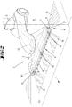
- FIG. 4 a further embodiment of the suction nozzle 2 is shown, which has a cleaning element 14, here a bristle element.
- the cleaning element 14 can be displaced relative to the housing of the suction nozzle 2, depending on the detection result of the obstacle sensor 10, 11, ie the presence of an obstacle 15.
- the cleaning element 14 can be arranged pivotably about an axis of rotation on the housing of the suction nozzle 2 and, for example, by means of a servomotor from a cleaning position to a rest position, and vice versa, be displaced.
- the invention works in such a way that the vacuum cleaner 1 is guided with the suction nozzle 2 over the surface 13 to be cleaned.
- the obstacle sensors 10, 11 in operation and detect in their respective detection area 16 a presence or Absence of an obstacle 15 on the to be cleaned Area 13.
- a basic position of the limiting means 8, 9 of the suction nozzle 2 provide that both the front of the suction nozzle 2 frontally arranged limiting means 8 and the parallel to the direction of movement x aligned lateral limiting means 9 in a blocking state on the Saugrandabêten 6, the 7th are arranged.
- the limiting means 8, 9 with their free end portion in contact with the surface to be cleaned 13.
- fine suction material such as. Dust, as before by the limiting means 8, 9 pass into the suction mouth 3 of the suction nozzle 2, so that the surface to be cleaned 13 can be sucked off in a conventional cleaning operation.
- the obstacle sensors 10, 11 continuously transmit their detection result to the evaluation and control device 12, which compares the detection results with reference results stored in a data memory.
- the detection result of the obstacle sensor 10, 11 may, for example, be a measured distance to an obstacle 15.
- the stored reference result is a limit distance which indicates the distance between the suction nozzle 2 and an obstacle 15, below which a limiting means 8, 9 nearest the obstacle 15 are displaced into an opening state.
- the evaluation and control device 12 controls an actuator assigned to the respective limiting means 8, 9, for example a servomotor, so that the limiting means 8, 9 can be removed from the surface 13 to be cleaned.
- the evaluation and control device 12 determines that the detection results transmitted by the obstacle sensors 10, 11 again have a distance which is greater than the limit distance, the previously raised limiting means 8, 9 are again shifted into the blocking state, in which the latter cleaning surface 13 contacted.
- the evaluation and control device 12 also take into account operating or sensor data of the vacuum cleaner 1, so that, for example, a displacement of the limiting means 8, 9 is possible only when a minimum value for negative pressure and / or volume flow of a blower of the vacuum cleaner 1 is exceeded.
- the limiting means 8, 9 of the Saugrandabitese 6, 7 are spaced in a blocking state of the surface to be cleaned 13 by a defined amount, so that smaller coarse material between the surface to be cleaned 13 and the limiting means 8, 9 in the suction mouth 3 can get. If one of the obstacle sensors 11 detects an obstacle 15, which has a distance to the suction nozzle 2 which is smaller than the limit distance, the limiting means 9 of the closest to the obstacle 15 Saugrandabêtes 7 is shifted to the open state, so that between the obstacle 15 and the suction nozzle 2 forms a flow channel which concentrates the suction force of the suction fan on this flow channel and thus enables optimal dust absorption in front of the obstacle 15.
- the evaluation and control device 12 controls the other limiting means 8 so that they are placed on the surface to be cleaned 13, so that the remaining Saugrandabitese 6 are blocked by the limiting means 8, so that only fine material on this Saugrandabitese 6 get into the suction 3 can.
- the limiting means 9 arranged there is also placed on the surface 13 to be cleaned.
- blocking states and opening states of different limiting means 8, 9 are possible.
- one or more Limiting means 8, 9 are displaced in an open state, while other limiting means 8, 9 are in a partially blocking blocking state, in which the limiting means 8, 9 are also not placed on the surface to be cleaned 13, but these are approximated.
- the suction nozzle 2 is also moved as usual on the surface to be cleaned 13.
- the obstacle sensors 10, 11 monitor the detection area 16 in front of the respective associated suction edge section 6, 7.
- the cleaning agent 14 which is the respective obstacle 15 closest, such that the cleaning element 14 is pivoted out of a portion of the housing of the suction nozzle 2, and can be brought to the obstacle 15 for conditioning.
- the cleaning element 14 is here, for example, a bristle element whose bristles with their free end regions on the obstacle 15, here a baseboard and a portion of a wall, can stroke.
- the cleaning element 14 is advantageously immediately adjacent to the respective suction edge section 6, 7, so that the suction material released from the obstacle 15 can be sucked into the suction mouth 3 immediately through the opened suction edge section 6, 7.
- the cleaning elements 14 are shaped and dimensioned so that the bristles are arranged at least in a range of about 1 to 10 cm to the surface to be cleaned 13 and thus can free the horizontally extending edge of a skirting of suction material.
- the obstacle sensor 10, 11 assigned to the corresponding suction edge section 6, 7 measures an exceeding of the limit distance to the obstacle 15
- the cleaning element 14 is returned to the housing of the suction nozzle 2 shifted back so that it no longer protrudes beyond the contour of the suction nozzle 2.
Landscapes
- Engineering & Computer Science (AREA)
- Mechanical Engineering (AREA)
- Nozzles For Electric Vacuum Cleaners (AREA)
- Electric Vacuum Cleaner (AREA)
Claims (10)
- Buse d'aspiration (2) pour un aspirateur (1) pour aspirer un matériau d'aspiration depuis une surface à nettoyer (13) au moyen d'un flux d'air d'aspiration, dans laquelle la buse d'aspiration (2) présente une bouche d'aspiration (3) pouvant être agencée à proximité de la surface à nettoyer (13) et présentant un bord d'aspiration (4) délimitant une surface partielle sur laquelle vient agir le flux d'air d'aspiration et une ouverture (5) de sortie du flux d'air d'aspiration, ainsi qu'un moyen de délimitation (8, 9) associé au bord d'aspiration (4), qui peut être commandé en fonction d'un résultat de détection d'un capteur, le capteur étant un capteur d'obstacle (10, 11) pour détecter un obstacle {15) sensiblement fixe situé devant la buse d'aspiration (2), en particulier un mur ou un meuble, le capteur d'obstacle {10, 11) étant agencé pour détecter des obstacles {15) qui sont disposés à l'extérieur de la zone partielle de la surface (13) surplombée par la buse d'aspiration (2) et qui, par rapport à un agencement de la buse d'aspiration (2) lors d'une opération de nettoyage habituelle, font saillie au-dessus d'un plan de bord d'aspiration comprenant le bord d'aspiration (4), caractérisé en ce que le moyen de délimitation (8, 9) ne peut être déplacé dans l'état d'ouverture que lorsque la distance entre la buse d'aspiration (2) et l'obstacle (15) passe sous une distance limite définie.
- Buse d'aspiration (2) selon la revendication 1, caractérisée en ce qu'au moins un moyen de délimitation (8, 9) peut être déplacé d'un état d'obstruction qui obstrue au moins partiellement une partie de bord d'aspiration (6, 7) du bord d'aspiration (4) à un état d'ouverture qui libère complètement la partie de bord d'aspiration (6, 7), et vice versa.
- Buse d'aspiration (2) selon la revendication 1 ou 2, caractérisée en ce qu'une première partie de bord d'aspiration (6, 7) du bord d'aspiration (4) présente un premier moyen de délimitation (8) et en ce qu'une deuxième partie de bord d'aspiration (7) du bord d'aspiration (4) présente un deuxième moyen de délimitation (9), lesquels moyens de délimitation (8, 9) peuvent être déplacés indépendamment l'un de l'autre, notamment aussi dans des directions opposées, en fonction du résultat de détection d'un détecteur d'obstacle (10, 11) ou de plusieurs détecteurs d'obstacle (10, 11).
- Buse d'aspiration (2) selon l'une des revendications précédentes, caractérisée en ce que la distance limite est inférieure à 50 mm, de préférence inférieure à 15 mm.
- Buse d'aspiration (2) selon l'une des revendications précédentes, caractérisée en ce qu'une première partie de bord d'aspiration (6) est orientée sensiblement perpendiculairement à une direction de déplacement habituelle (x) de la buse d'aspiration (2), et qu'une deuxième partie de bord d'aspiration (7) est orientée sensiblement parallèlement à la direction de déplacement (x).
- Buse d'aspiration (2) selon l'une des revendications précédentes, caractérisée par au moins un élément de nettoyage (14), en particulier un élément à poils, qui est déplaçable par rapport aux autres zones partielles de la buse d'aspiration (2) en fonction du résultat de détection du capteur d'obstacle (10, 11), en particulier pour nettoyer un obstacle (15) agencé perpendiculairement à la surface à nettoyer (13).
- Aspirateur (1), en particulier aspirateur de sol domestique guidé à la main ou à déplacement automatique, pour aspirer un matériau d'aspiration d'une surface à nettoyer (13) au moyen d'un flux d'air d'aspiration, caractérisé par une buse d'aspiration (2) selon l'une des revendications précédentes.
- Procédé pour aspirer un matériau d'aspiration depuis une surface à nettoyer (13) au moyen d'une buse d'aspiration (2) qui présente une bouche d'aspiration (3) pouvant être agencée à proximité de la surface à nettoyer (13) et présentant un bord d'aspiration (4), dans lequel un moyen de délimitation (8, 9) associé au bord d'aspiration (4) est commandé en fonction du résultat de détection d'un capteur, dans lequel le capteur en tant que capteur d'obstacle (10, 11) détecte une présence ou absence d'un obstacle (15) sensiblement fixe, en particulier un mur ou un meuble, devant la buse d'aspiration (2) à l'extérieur de la zone partielle de la surface (13) surplombée par la buse d'aspiration (2) et au-dessus d'un plan de bord d'aspiration comprenant le bord d'aspiration (4) en référence à un agencement de la buse d'aspiration (2) lors d'une opération de nettoyage habituelle, et transmet le résultat de détection à un dispositif d'évaluation et de commande (12), à la suite de quoi le dispositif d'évaluation et de commande commande le moyen de délimitation (8, 9), en particulier l'éloigne de la surface à nettoyer (13) et/ou l'approche de la surface à nettoyer (13), caractérisé en ce que le moyen de délimitation (8, 9) n'est déplacé dans l'état d'ouverture que lorsque la distance entre la buse d'aspiration (2) et l'obstacle (15) passe au-dessous d'une distance limite définie.
- Procédé selon la revendication 8, caractérisé en ce qu'au moins un moyen de délimitation (8, 9) obstrue au moins partiellement une partie de bord d'aspiration (6, 7) du bord d'aspiration (4) en l'absence d'un obstacle (15), et dans lequel le moyen de délimitation (8, 9) est éloigné de la surface à nettoyer (13) dès qu'un obstacle (15) passe sous la distance limite définie avec le bord d'aspiration (2).
- Procédé selon la revendication 9, caractérisé en ce qu'un moyen de délimitation (8, 9) d'une partie de bord d'aspiration (6, 7) devant laquelle aucun obstacle (15) n'est détecté, est abaissé sur la surface à nettoyer (13) lorsqu'un obstacle (15) est détecté devant une autre partie de bord d'aspiration (6, 7).
Applications Claiming Priority (2)
| Application Number | Priority Date | Filing Date | Title |
|---|---|---|---|
| DE102015109838.5A DE102015109838A1 (de) | 2015-06-19 | 2015-06-19 | Saugdüse für einen Staubsauger |
| PCT/EP2016/062629 WO2016202610A1 (fr) | 2015-06-19 | 2016-06-03 | Buse d'aspiration pour un aspirateur |
Publications (2)
| Publication Number | Publication Date |
|---|---|
| EP3310233A1 EP3310233A1 (fr) | 2018-04-25 |
| EP3310233B1 true EP3310233B1 (fr) | 2019-11-27 |
Family
ID=56101458
Family Applications (1)
| Application Number | Title | Priority Date | Filing Date |
|---|---|---|---|
| EP16727182.4A Active EP3310233B1 (fr) | 2015-06-19 | 2016-06-03 | Buse d'aspiration pour un aspirateur |
Country Status (9)
| Country | Link |
|---|---|
| US (1) | US10555654B2 (fr) |
| EP (1) | EP3310233B1 (fr) |
| JP (1) | JP2018517475A (fr) |
| CN (1) | CN107708512B (fr) |
| DE (1) | DE102015109838A1 (fr) |
| ES (1) | ES2762921T3 (fr) |
| SG (1) | SG11201708990RA (fr) |
| TW (1) | TWI692340B (fr) |
| WO (1) | WO2016202610A1 (fr) |
Families Citing this family (11)
| Publication number | Priority date | Publication date | Assignee | Title |
|---|---|---|---|---|
| DE102017112741A1 (de) * | 2017-06-09 | 2018-12-13 | Vorwerk & Co. Interholding Gmbh | Staubsauger mit Objekterkennung und Verfahren zum Betreiben eines Staubsaugers |
| JP6848798B2 (ja) * | 2017-10-03 | 2021-03-24 | 三菱電機株式会社 | 電気掃除機 |
| CN108113575A (zh) * | 2018-02-08 | 2018-06-05 | 江苏美的清洁电器股份有限公司 | 吸尘器的吸头组件及吸尘器 |
| FR3078244B1 (fr) * | 2018-02-23 | 2021-02-19 | Seb Sa | Suceur d'aspirateur combinant une premiere et une deuxieme tete d'aspiration reliees entre elles par un systeme d'articulation |
| FR3078245B1 (fr) | 2018-02-23 | 2020-02-07 | Seb S.A. | Suceur d’aspirateur combinant une premiere tete d’aspiration et une deuxieme tete d’aspiration |
| CN108720715A (zh) * | 2018-04-04 | 2018-11-02 | 宛敏玖 | 一种分体式家用吸尘器 |
| CN110522351A (zh) * | 2018-05-23 | 2019-12-03 | 天佑电器(苏州)有限公司 | 吸尘器 |
| DE102018126107A1 (de) * | 2018-10-19 | 2020-04-23 | Vorwerk & Co. Interholding Gmbh | Saugreinigungsgerät mit Sensoren zur Detektion von elektrisch geladenen Partikeln |
| JP2020081333A (ja) * | 2018-11-22 | 2020-06-04 | 東芝ライフスタイル株式会社 | 電気掃除機 |
| BR112023001161A2 (pt) * | 2020-07-23 | 2023-04-04 | Koninklijke Philips Nv | Dispositivo de bocal e eletrodoméstico de limpeza sem fio |
| WO2022242851A1 (fr) | 2021-05-19 | 2022-11-24 | Alfred Kärcher SE & Co. KG | Appareil de buse pour sol et dispositif de nettoyage par aspiration |
Family Cites Families (10)
| Publication number | Priority date | Publication date | Assignee | Title |
|---|---|---|---|---|
| JPH05253122A (ja) * | 1992-03-12 | 1993-10-05 | Matsushita Electric Ind Co Ltd | 電気掃除機用床ノズル |
| DE50110028D1 (de) * | 2000-12-13 | 2006-07-20 | Vorwerk Co Interholding | Düse für einen Staubsauger |
| JP4268911B2 (ja) * | 2004-08-04 | 2009-05-27 | 日立アプライアンス株式会社 | 自走式掃除機 |
| JP4621544B2 (ja) * | 2005-06-08 | 2011-01-26 | 株式会社東芝 | 吸込口体及びこれを備える電気掃除機 |
| DE102005061646A1 (de) * | 2005-12-22 | 2007-06-28 | Vorwerk & Co. Interholding Gmbh | Verfahren zum Betreiben einer Bodendüse, sowie Bodendüse für einen Staubsauger |
| ATE545356T1 (de) * | 2006-12-21 | 2012-03-15 | Koninkl Philips Electronics Nv | Reinigungsdüse und verfahren zum staubsaugen |
| SE532296C2 (sv) * | 2008-04-15 | 2009-12-08 | Electrolux Ab | Munstycke |
| CA2658161A1 (fr) * | 2009-03-13 | 2010-09-13 | G.B.D. Corp. | Tete de nettoyage de surfaces |
| JP2013248194A (ja) * | 2012-05-31 | 2013-12-12 | Twinbird Corp | 掃除機用ノズル装置 |
| US9962051B2 (en) * | 2013-09-04 | 2018-05-08 | Bissell Homecare, Inc. | Vacuum cleaner |
-
2015
- 2015-06-19 DE DE102015109838.5A patent/DE102015109838A1/de not_active Withdrawn
-
2016
- 2016-06-03 SG SG11201708990RA patent/SG11201708990RA/en unknown
- 2016-06-03 EP EP16727182.4A patent/EP3310233B1/fr active Active
- 2016-06-03 JP JP2017560276A patent/JP2018517475A/ja active Pending
- 2016-06-03 CN CN201680033335.0A patent/CN107708512B/zh active Active
- 2016-06-03 US US15/575,012 patent/US10555654B2/en active Active
- 2016-06-03 ES ES16727182T patent/ES2762921T3/es active Active
- 2016-06-03 WO PCT/EP2016/062629 patent/WO2016202610A1/fr active Application Filing
- 2016-06-13 TW TW105118369A patent/TWI692340B/zh not_active IP Right Cessation
Non-Patent Citations (1)
| Title |
|---|
| None * |
Also Published As
| Publication number | Publication date |
|---|---|
| TW201709863A (zh) | 2017-03-16 |
| SG11201708990RA (en) | 2017-11-29 |
| DE102015109838A1 (de) | 2016-12-22 |
| JP2018517475A (ja) | 2018-07-05 |
| EP3310233A1 (fr) | 2018-04-25 |
| US20180146832A1 (en) | 2018-05-31 |
| CN107708512A (zh) | 2018-02-16 |
| WO2016202610A1 (fr) | 2016-12-22 |
| US10555654B2 (en) | 2020-02-11 |
| TWI692340B (zh) | 2020-05-01 |
| CN107708512B (zh) | 2021-04-06 |
| ES2762921T3 (es) | 2020-05-26 |
Similar Documents
| Publication | Publication Date | Title |
|---|---|---|
| EP3310233B1 (fr) | Buse d'aspiration pour un aspirateur | |
| EP2939582B1 (fr) | Buse d'aspirateur | |
| EP2875765B1 (fr) | Suceur d'aspiration pour un aspirateur | |
| EP3351156B1 (fr) | Appareil de nettoyage se déplaçant automatiquement | |
| EP2893860B1 (fr) | Appareil d'entretien du sol doté d'une brosse à rouleaux entraînée | |
| EP3095368B1 (fr) | Buse de sol dur pour produits grossiers ou fines poussières | |
| EP3095369B1 (fr) | Buse d'aspiration pour produits grossiers et poussiere fine | |
| EP2116165B1 (fr) | Bas d'aspiration pour aspirateurs | |
| EP3095367B1 (fr) | Buse d'aspiration pour produits grossiers et poussiere fine | |
| DE102015108157A1 (de) | Saugdüse für einen Staubsauger | |
| EP2937029B1 (fr) | Buse d'aspiration destinée à aspirer des sols lisses, notamment des sols dallés | |
| DE102017208960A1 (de) | Staubsauger mit einem motorisch betriebenen Dichtmittel | |
| DE102018120544B4 (de) | Saugdüse für einen Staubsauger | |
| EP3050475A1 (fr) | Buse d'aspiration pour surfaces dures | |
| DE102017118487A1 (de) | Saugdüse für ein ein Sauggebläse aufweisendes Reinigungsgerät | |
| DE3131380A1 (de) | Reinigungswerkzeug zum saugreinigen | |
| EP3420872B1 (fr) | Buse de sol pour aspirateur et aspirateur | |
| DE19602723C2 (de) | Vorrichtung zum Betrieb eines Staubsaugers | |
| DE102015105173A1 (de) | Saugdüse für einen Staubsauger | |
| DE102018201237A1 (de) | Vorsatzgerät für einen Staubsauger | |
| EP3970589A1 (fr) | Robot aspirateur | |
| DE102015100873A1 (de) | Saugdüse | |
| EP2534991B1 (fr) | Buse de sol pour un aspirateur et aspirateur doté d'une telle buse de sol | |
| DE102017129800A1 (de) | Bodenplatte und Saugdüse mit einer Bodenplatte | |
| DE102014114030A1 (de) | Grobgutdichtlippen |
Legal Events
| Date | Code | Title | Description |
|---|---|---|---|
| STAA | Information on the status of an ep patent application or granted ep patent |
Free format text: STATUS: THE INTERNATIONAL PUBLICATION HAS BEEN MADE |
|
| PUAI | Public reference made under article 153(3) epc to a published international application that has entered the european phase |
Free format text: ORIGINAL CODE: 0009012 |
|
| STAA | Information on the status of an ep patent application or granted ep patent |
Free format text: STATUS: REQUEST FOR EXAMINATION WAS MADE |
|
| 17P | Request for examination filed |
Effective date: 20180115 |
|
| AK | Designated contracting states |
Kind code of ref document: A1 Designated state(s): AL AT BE BG CH CY CZ DE DK EE ES FI FR GB GR HR HU IE IS IT LI LT LU LV MC MK MT NL NO PL PT RO RS SE SI SK SM TR |
|
| AX | Request for extension of the european patent |
Extension state: BA ME |
|
| DAV | Request for validation of the european patent (deleted) | ||
| DAX | Request for extension of the european patent (deleted) | ||
| GRAP | Despatch of communication of intention to grant a patent |
Free format text: ORIGINAL CODE: EPIDOSNIGR1 |
|
| STAA | Information on the status of an ep patent application or granted ep patent |
Free format text: STATUS: GRANT OF PATENT IS INTENDED |
|
| INTG | Intention to grant announced |
Effective date: 20190626 |
|
| GRAS | Grant fee paid |
Free format text: ORIGINAL CODE: EPIDOSNIGR3 |
|
| GRAA | (expected) grant |
Free format text: ORIGINAL CODE: 0009210 |
|
| STAA | Information on the status of an ep patent application or granted ep patent |
Free format text: STATUS: THE PATENT HAS BEEN GRANTED |
|
| AK | Designated contracting states |
Kind code of ref document: B1 Designated state(s): AL AT BE BG CH CY CZ DE DK EE ES FI FR GB GR HR HU IE IS IT LI LT LU LV MC MK MT NL NO PL PT RO RS SE SI SK SM TR |
|
| REG | Reference to a national code |
Ref country code: GB Ref legal event code: FG4D Free format text: NOT ENGLISH |
|
| REG | Reference to a national code |
Ref country code: CH Ref legal event code: EP |
|
| REG | Reference to a national code |
Ref country code: AT Ref legal event code: REF Ref document number: 1205776 Country of ref document: AT Kind code of ref document: T Effective date: 20191215 |
|
| REG | Reference to a national code |
Ref country code: DE Ref legal event code: R096 Ref document number: 502016007747 Country of ref document: DE |
|
| REG | Reference to a national code |
Ref country code: IE Ref legal event code: FG4D Free format text: LANGUAGE OF EP DOCUMENT: GERMAN |
|
| REG | Reference to a national code |
Ref country code: NL Ref legal event code: MP Effective date: 20191127 |
|
| REG | Reference to a national code |
Ref country code: LT Ref legal event code: MG4D |
|
| PG25 | Lapsed in a contracting state [announced via postgrant information from national office to epo] |
Ref country code: NL Free format text: LAPSE BECAUSE OF FAILURE TO SUBMIT A TRANSLATION OF THE DESCRIPTION OR TO PAY THE FEE WITHIN THE PRESCRIBED TIME-LIMIT Effective date: 20191127 Ref country code: NO Free format text: LAPSE BECAUSE OF FAILURE TO SUBMIT A TRANSLATION OF THE DESCRIPTION OR TO PAY THE FEE WITHIN THE PRESCRIBED TIME-LIMIT Effective date: 20200227 Ref country code: BG Free format text: LAPSE BECAUSE OF FAILURE TO SUBMIT A TRANSLATION OF THE DESCRIPTION OR TO PAY THE FEE WITHIN THE PRESCRIBED TIME-LIMIT Effective date: 20200227 Ref country code: LT Free format text: LAPSE BECAUSE OF FAILURE TO SUBMIT A TRANSLATION OF THE DESCRIPTION OR TO PAY THE FEE WITHIN THE PRESCRIBED TIME-LIMIT Effective date: 20191127 Ref country code: FI Free format text: LAPSE BECAUSE OF FAILURE TO SUBMIT A TRANSLATION OF THE DESCRIPTION OR TO PAY THE FEE WITHIN THE PRESCRIBED TIME-LIMIT Effective date: 20191127 Ref country code: SE Free format text: LAPSE BECAUSE OF FAILURE TO SUBMIT A TRANSLATION OF THE DESCRIPTION OR TO PAY THE FEE WITHIN THE PRESCRIBED TIME-LIMIT Effective date: 20191127 Ref country code: LV Free format text: LAPSE BECAUSE OF FAILURE TO SUBMIT A TRANSLATION OF THE DESCRIPTION OR TO PAY THE FEE WITHIN THE PRESCRIBED TIME-LIMIT Effective date: 20191127 Ref country code: GR Free format text: LAPSE BECAUSE OF FAILURE TO SUBMIT A TRANSLATION OF THE DESCRIPTION OR TO PAY THE FEE WITHIN THE PRESCRIBED TIME-LIMIT Effective date: 20200228 |
|
| REG | Reference to a national code |
Ref country code: ES Ref legal event code: FG2A Ref document number: 2762921 Country of ref document: ES Kind code of ref document: T3 Effective date: 20200526 |
|
| PG25 | Lapsed in a contracting state [announced via postgrant information from national office to epo] |
Ref country code: RS Free format text: LAPSE BECAUSE OF FAILURE TO SUBMIT A TRANSLATION OF THE DESCRIPTION OR TO PAY THE FEE WITHIN THE PRESCRIBED TIME-LIMIT Effective date: 20191127 Ref country code: HR Free format text: LAPSE BECAUSE OF FAILURE TO SUBMIT A TRANSLATION OF THE DESCRIPTION OR TO PAY THE FEE WITHIN THE PRESCRIBED TIME-LIMIT Effective date: 20191127 Ref country code: IS Free format text: LAPSE BECAUSE OF FAILURE TO SUBMIT A TRANSLATION OF THE DESCRIPTION OR TO PAY THE FEE WITHIN THE PRESCRIBED TIME-LIMIT Effective date: 20200327 |
|
| PG25 | Lapsed in a contracting state [announced via postgrant information from national office to epo] |
Ref country code: AL Free format text: LAPSE BECAUSE OF FAILURE TO SUBMIT A TRANSLATION OF THE DESCRIPTION OR TO PAY THE FEE WITHIN THE PRESCRIBED TIME-LIMIT Effective date: 20191127 |
|
| PG25 | Lapsed in a contracting state [announced via postgrant information from national office to epo] |
Ref country code: PT Free format text: LAPSE BECAUSE OF FAILURE TO SUBMIT A TRANSLATION OF THE DESCRIPTION OR TO PAY THE FEE WITHIN THE PRESCRIBED TIME-LIMIT Effective date: 20200419 Ref country code: RO Free format text: LAPSE BECAUSE OF FAILURE TO SUBMIT A TRANSLATION OF THE DESCRIPTION OR TO PAY THE FEE WITHIN THE PRESCRIBED TIME-LIMIT Effective date: 20191127 Ref country code: EE Free format text: LAPSE BECAUSE OF FAILURE TO SUBMIT A TRANSLATION OF THE DESCRIPTION OR TO PAY THE FEE WITHIN THE PRESCRIBED TIME-LIMIT Effective date: 20191127 Ref country code: DK Free format text: LAPSE BECAUSE OF FAILURE TO SUBMIT A TRANSLATION OF THE DESCRIPTION OR TO PAY THE FEE WITHIN THE PRESCRIBED TIME-LIMIT Effective date: 20191127 |
|
| PGFP | Annual fee paid to national office [announced via postgrant information from national office to epo] |
Ref country code: CZ Payment date: 20200521 Year of fee payment: 5 |
|
| REG | Reference to a national code |
Ref country code: DE Ref legal event code: R097 Ref document number: 502016007747 Country of ref document: DE |
|
| PG25 | Lapsed in a contracting state [announced via postgrant information from national office to epo] |
Ref country code: SM Free format text: LAPSE BECAUSE OF FAILURE TO SUBMIT A TRANSLATION OF THE DESCRIPTION OR TO PAY THE FEE WITHIN THE PRESCRIBED TIME-LIMIT Effective date: 20191127 Ref country code: SK Free format text: LAPSE BECAUSE OF FAILURE TO SUBMIT A TRANSLATION OF THE DESCRIPTION OR TO PAY THE FEE WITHIN THE PRESCRIBED TIME-LIMIT Effective date: 20191127 |
|
| PLBE | No opposition filed within time limit |
Free format text: ORIGINAL CODE: 0009261 |
|
| STAA | Information on the status of an ep patent application or granted ep patent |
Free format text: STATUS: NO OPPOSITION FILED WITHIN TIME LIMIT |
|
| 26N | No opposition filed |
Effective date: 20200828 |
|
| PG25 | Lapsed in a contracting state [announced via postgrant information from national office to epo] |
Ref country code: SI Free format text: LAPSE BECAUSE OF FAILURE TO SUBMIT A TRANSLATION OF THE DESCRIPTION OR TO PAY THE FEE WITHIN THE PRESCRIBED TIME-LIMIT Effective date: 20191127 Ref country code: PL Free format text: LAPSE BECAUSE OF FAILURE TO SUBMIT A TRANSLATION OF THE DESCRIPTION OR TO PAY THE FEE WITHIN THE PRESCRIBED TIME-LIMIT Effective date: 20191127 |
|
| PG25 | Lapsed in a contracting state [announced via postgrant information from national office to epo] |
Ref country code: MC Free format text: LAPSE BECAUSE OF FAILURE TO SUBMIT A TRANSLATION OF THE DESCRIPTION OR TO PAY THE FEE WITHIN THE PRESCRIBED TIME-LIMIT Effective date: 20191127 |
|
| REG | Reference to a national code |
Ref country code: CH Ref legal event code: PL |
|
| GBPC | Gb: european patent ceased through non-payment of renewal fee |
Effective date: 20200603 |
|
| PG25 | Lapsed in a contracting state [announced via postgrant information from national office to epo] |
Ref country code: LU Free format text: LAPSE BECAUSE OF NON-PAYMENT OF DUE FEES Effective date: 20200603 |
|
| REG | Reference to a national code |
Ref country code: BE Ref legal event code: MM Effective date: 20200630 |
|
| PG25 | Lapsed in a contracting state [announced via postgrant information from national office to epo] |
Ref country code: LI Free format text: LAPSE BECAUSE OF NON-PAYMENT OF DUE FEES Effective date: 20200630 Ref country code: CH Free format text: LAPSE BECAUSE OF NON-PAYMENT OF DUE FEES Effective date: 20200630 Ref country code: IE Free format text: LAPSE BECAUSE OF NON-PAYMENT OF DUE FEES Effective date: 20200603 Ref country code: GB Free format text: LAPSE BECAUSE OF NON-PAYMENT OF DUE FEES Effective date: 20200603 |
|
| PG25 | Lapsed in a contracting state [announced via postgrant information from national office to epo] |
Ref country code: BE Free format text: LAPSE BECAUSE OF NON-PAYMENT OF DUE FEES Effective date: 20200630 |
|
| PG25 | Lapsed in a contracting state [announced via postgrant information from national office to epo] |
Ref country code: CZ Free format text: LAPSE BECAUSE OF NON-PAYMENT OF DUE FEES Effective date: 20210603 |
|
| PG25 | Lapsed in a contracting state [announced via postgrant information from national office to epo] |
Ref country code: TR Free format text: LAPSE BECAUSE OF FAILURE TO SUBMIT A TRANSLATION OF THE DESCRIPTION OR TO PAY THE FEE WITHIN THE PRESCRIBED TIME-LIMIT Effective date: 20191127 Ref country code: MT Free format text: LAPSE BECAUSE OF FAILURE TO SUBMIT A TRANSLATION OF THE DESCRIPTION OR TO PAY THE FEE WITHIN THE PRESCRIBED TIME-LIMIT Effective date: 20191127 Ref country code: CY Free format text: LAPSE BECAUSE OF FAILURE TO SUBMIT A TRANSLATION OF THE DESCRIPTION OR TO PAY THE FEE WITHIN THE PRESCRIBED TIME-LIMIT Effective date: 20191127 |
|
| PG25 | Lapsed in a contracting state [announced via postgrant information from national office to epo] |
Ref country code: MK Free format text: LAPSE BECAUSE OF FAILURE TO SUBMIT A TRANSLATION OF THE DESCRIPTION OR TO PAY THE FEE WITHIN THE PRESCRIBED TIME-LIMIT Effective date: 20191127 |
|
| REG | Reference to a national code |
Ref country code: AT Ref legal event code: MM01 Ref document number: 1205776 Country of ref document: AT Kind code of ref document: T Effective date: 20210603 |
|
| PG25 | Lapsed in a contracting state [announced via postgrant information from national office to epo] |
Ref country code: AT Free format text: LAPSE BECAUSE OF NON-PAYMENT OF DUE FEES Effective date: 20210603 |
|
| P01 | Opt-out of the competence of the unified patent court (upc) registered |
Effective date: 20230517 |
|
| PGFP | Annual fee paid to national office [announced via postgrant information from national office to epo] |
Ref country code: FR Payment date: 20230620 Year of fee payment: 8 Ref country code: DE Payment date: 20230620 Year of fee payment: 8 |
|
| PGFP | Annual fee paid to national office [announced via postgrant information from national office to epo] |
Ref country code: IT Payment date: 20230630 Year of fee payment: 8 Ref country code: ES Payment date: 20230719 Year of fee payment: 8 |