EP3308874B1 - Procédé, module et appareil destinés à un traitement par roulage de filet externe sur un tuyau et ligne de production de filet externe sur un tuyau - Google Patents
Procédé, module et appareil destinés à un traitement par roulage de filet externe sur un tuyau et ligne de production de filet externe sur un tuyau Download PDFInfo
- Publication number
- EP3308874B1 EP3308874B1 EP16806858.3A EP16806858A EP3308874B1 EP 3308874 B1 EP3308874 B1 EP 3308874B1 EP 16806858 A EP16806858 A EP 16806858A EP 3308874 B1 EP3308874 B1 EP 3308874B1
- Authority
- EP
- European Patent Office
- Prior art keywords
- rolling
- rolling wheel
- head
- pipe thread
- disc
- Prior art date
- Legal status (The legal status is an assumption and is not a legal conclusion. Google has not performed a legal analysis and makes no representation as to the accuracy of the status listed.)
- Active
Links
- 238000000034 method Methods 0.000 title claims description 94
- 238000012545 processing Methods 0.000 title claims description 82
- 238000004519 manufacturing process Methods 0.000 title claims description 16
- 238000005096 rolling process Methods 0.000 claims description 1294
- 230000008569 process Effects 0.000 claims description 53
- 238000002156 mixing Methods 0.000 claims description 29
- 238000005520 cutting process Methods 0.000 description 32
- 229910000831 Steel Inorganic materials 0.000 description 30
- 239000010959 steel Substances 0.000 description 30
- 238000013461 design Methods 0.000 description 14
- 239000000463 material Substances 0.000 description 14
- 230000005540 biological transmission Effects 0.000 description 12
- 230000004323 axial length Effects 0.000 description 11
- 238000005516 engineering process Methods 0.000 description 10
- 238000012937 correction Methods 0.000 description 9
- 238000009826 distribution Methods 0.000 description 9
- 238000007667 floating Methods 0.000 description 9
- 230000009286 beneficial effect Effects 0.000 description 6
- 230000001965 increasing effect Effects 0.000 description 6
- 238000009434 installation Methods 0.000 description 6
- 230000000630 rising effect Effects 0.000 description 6
- 230000009467 reduction Effects 0.000 description 5
- 230000009471 action Effects 0.000 description 4
- 238000003754 machining Methods 0.000 description 4
- 229910052751 metal Inorganic materials 0.000 description 4
- 239000002184 metal Substances 0.000 description 4
- 238000002360 preparation method Methods 0.000 description 4
- 238000004080 punching Methods 0.000 description 4
- RYGMFSIKBFXOCR-UHFFFAOYSA-N Copper Chemical compound [Cu] RYGMFSIKBFXOCR-UHFFFAOYSA-N 0.000 description 3
- 241000692569 Stylephorus chordatus Species 0.000 description 3
- 230000008901 benefit Effects 0.000 description 3
- 239000010949 copper Substances 0.000 description 3
- 238000001125 extrusion Methods 0.000 description 3
- 230000001788 irregular Effects 0.000 description 3
- 230000003321 amplification Effects 0.000 description 2
- 239000011248 coating agent Substances 0.000 description 2
- 238000000576 coating method Methods 0.000 description 2
- 229910052802 copper Inorganic materials 0.000 description 2
- 238000010586 diagram Methods 0.000 description 2
- 230000002708 enhancing effect Effects 0.000 description 2
- 238000000227 grinding Methods 0.000 description 2
- 238000010438 heat treatment Methods 0.000 description 2
- 239000000203 mixture Substances 0.000 description 2
- 238000003199 nucleic acid amplification method Methods 0.000 description 2
- 238000012360 testing method Methods 0.000 description 2
- 239000002699 waste material Substances 0.000 description 2
- BEIGFKLRGRRJJA-JLHYYAGUSA-O 2-(2f-benzothiazolyl)-5-styryl-3-(4f-phthalhydrazidyl)tetrazolium chloride Chemical compound C=1C=C2C(=O)NNC(=O)C2=CC=1[N+](N(N=1)C=2SC3=CC=CC=C3N=2)=NC=1\C=C\C1=CC=CC=C1 BEIGFKLRGRRJJA-JLHYYAGUSA-O 0.000 description 1
- 229910000838 Al alloy Inorganic materials 0.000 description 1
- 229910000851 Alloy steel Inorganic materials 0.000 description 1
- 229910000975 Carbon steel Inorganic materials 0.000 description 1
- 229910000881 Cu alloy Inorganic materials 0.000 description 1
- 229910001200 Ferrotitanium Inorganic materials 0.000 description 1
- 229910001335 Galvanized steel Inorganic materials 0.000 description 1
- 229910001209 Low-carbon steel Inorganic materials 0.000 description 1
- 239000008186 active pharmaceutical agent Substances 0.000 description 1
- 229910052782 aluminium Inorganic materials 0.000 description 1
- XAGFODPZIPBFFR-UHFFFAOYSA-N aluminium Chemical compound [Al] XAGFODPZIPBFFR-UHFFFAOYSA-N 0.000 description 1
- 238000004458 analytical method Methods 0.000 description 1
- 230000015572 biosynthetic process Effects 0.000 description 1
- 238000004364 calculation method Methods 0.000 description 1
- 239000010962 carbon steel Substances 0.000 description 1
- 238000010276 construction Methods 0.000 description 1
- 230000003247 decreasing effect Effects 0.000 description 1
- 230000007547 defect Effects 0.000 description 1
- 230000000694 effects Effects 0.000 description 1
- 230000005489 elastic deformation Effects 0.000 description 1
- 239000012530 fluid Substances 0.000 description 1
- 239000008397 galvanized steel Substances 0.000 description 1
- 230000006698 induction Effects 0.000 description 1
- 230000013011 mating Effects 0.000 description 1
- 230000009347 mechanical transmission Effects 0.000 description 1
- 230000001151 other effect Effects 0.000 description 1
- 238000003672 processing method Methods 0.000 description 1
- 230000000750 progressive effect Effects 0.000 description 1
- 238000012797 qualification Methods 0.000 description 1
- 230000002040 relaxant effect Effects 0.000 description 1
- 238000011160 research Methods 0.000 description 1
- 238000010079 rubber tapping Methods 0.000 description 1
- 238000007789 sealing Methods 0.000 description 1
- 239000010935 stainless steel Substances 0.000 description 1
- 229910001220 stainless steel Inorganic materials 0.000 description 1
- 238000005728 strengthening Methods 0.000 description 1
- 238000012546 transfer Methods 0.000 description 1
Images


Classifications
-
- B—PERFORMING OPERATIONS; TRANSPORTING
- B21—MECHANICAL METAL-WORKING WITHOUT ESSENTIALLY REMOVING MATERIAL; PUNCHING METAL
- B21H—MAKING PARTICULAR METAL OBJECTS BY ROLLING, e.g. SCREWS, WHEELS, RINGS, BARRELS, BALLS
- B21H3/00—Making helical bodies or bodies having parts of helical shape
- B21H3/02—Making helical bodies or bodies having parts of helical shape external screw-threads ; Making dies for thread rolling
- B21H3/04—Making by means of profiled-rolls or die rolls
- B21H3/042—Thread-rolling heads
-
- B—PERFORMING OPERATIONS; TRANSPORTING
- B21—MECHANICAL METAL-WORKING WITHOUT ESSENTIALLY REMOVING MATERIAL; PUNCHING METAL
- B21H—MAKING PARTICULAR METAL OBJECTS BY ROLLING, e.g. SCREWS, WHEELS, RINGS, BARRELS, BALLS
- B21H3/00—Making helical bodies or bodies having parts of helical shape
- B21H3/02—Making helical bodies or bodies having parts of helical shape external screw-threads ; Making dies for thread rolling
- B21H3/04—Making by means of profiled-rolls or die rolls
-
- B—PERFORMING OPERATIONS; TRANSPORTING
- B21—MECHANICAL METAL-WORKING WITHOUT ESSENTIALLY REMOVING MATERIAL; PUNCHING METAL
- B21H—MAKING PARTICULAR METAL OBJECTS BY ROLLING, e.g. SCREWS, WHEELS, RINGS, BARRELS, BALLS
- B21H3/00—Making helical bodies or bodies having parts of helical shape
- B21H3/02—Making helical bodies or bodies having parts of helical shape external screw-threads ; Making dies for thread rolling
Definitions
- the present invention relates to a method, a module, an apparatus for rolling external pipe thread and an external pipe thread production line of a steel pipe or a hollow blank, especially a common steel pipe, belonging to the pipe processing mechanical field.
- the external pipe thread by rolling has significant advantages of good quality, good sealing performance and high mechanical connection strength, and is valued by more and more people.
- outer diameter, wall thickness and other parameters of existing general steel pipe are formulated based on the cutting process requirements.
- the outer diameter is too large and the steep pipe has a certain degree of non-roundness.
- the both constitute two biggest problems for rolling an external pipe thread.
- the problem of the large outer diameter can be solved by methods such as axial punching of a conical surface or a cylindrical surface or a radial rolling to reduce diameter, or using a medium-diameter pipe conforming to the rolling requirement.
- the method adopted at present for solving the irregularity of non-roundness problem is a kind of axially punched perfect conical surface disclosed in patent CN1251820C or a method of firstly cutting the perfect conical surface with the tool in the external pipe thread section of the steel pipe for processing pipe and then performing the conical external pipe thread rolling processing disclosed by the patent CN2582780Y .
- SU 782937A relates to the field of metal forming and, in particular, can be used in the manufacture of external cylindrical threads on pipes and pipe products.
- This document discloses a process module for rolling an external pipe thread, comprising a first rolling head and a second rolling head, wherein the first rolling head comprises circumferentially arranged first rolling wheels; the first rolling wheel is a rolling wheel with a smooth outer surface; and wherein the second rolling head comprises circumferentially arranged second rolling wheels having an external pipe thread forming portion.
- Axially punching has the problems of complex apparatus and damage to the steel pipe, and firstly cutting the perfect conical surface with the tool in the external pipe thread section needs high processing precision, such as high concentricity of the workpiece and the tool, which can not be easily achieved in construction site for installing the pipe network.
- the market needs new external pipe thread processing technology and pipe external pipe thread processing apparatus which has reasonable structural design and high applicability.
- the purpose of the present invention is to provide a method, a module and an apparatus for rolling external pipe thread and a rolling production line thereof with high applicability. More specifically, the present invention provides a method, module, an apparatus and a rolling production line that can use conventional steel pipe having a standard outer diameter and non-roundness as a blank, without applying a preparatory process that need a die stamping or cutting a conical surface with a tool, and complete the preparation process by the pre-rolling of the present invention, and then form external pipe thread by rolling.
- the present invention provides a rolling method for forming an external pipe thread, comprising rolling a hollow blank in sequence by a first rolling wheel group and a second rolling wheel group, wherein the first rolling wheel group comprises at least four circumferentially arranged first rolling wheels, the second rolling wheel group comprises at least three circumferentially arranged second rolling wheels, wherein the first rolling wheels are rolling wheels with smooth outer surface, and the second rolling wheels have external pipe thread forming portion, and the rolling method includes the following steps:
- the number of the first rolling wheels in the first rolling wheel group is greater than the number of the second rolling wheels in the second rolling wheel group.
- the hollow blank has non-roundness greater than 100 um.
- the rolling process of the first rolling wheel group and the second rolling wheel group is selected from one of the following cooperation:
- both the number of the first rolling wheels in the first rolling wheel group and the number of the second rolling wheels in the second rolling wheel group is no more than 15, preferably 4, 5, 6, 7, 8, or 9; or when used to process an external pipe thread on a hollow blank having a size between 2 and 4 inches, both the number of the first rolling wheels in the first rolling wheel group and the second rolling wheels in the second rolling wheel group is no more than 19, preferably 4, 5, 6, 7, 8, 9, 10, or 11; or when used to process an external pipe thread on a hollow blank having a size of 4 inches or more, both the number of the first rolling wheels in the first rolling wheel group and the number of the second rolling wheels in the second rolling wheel group is no more than 35, preferably 4, 5, 6, 7, 8, 9, 10, 11, 12, 13,14,15,16 , 17, 18, 19 or 20.
- the number of the first rolling wheels in the first rolling wheel group is different from the number of the second rolling wheels in the second rolling wheel group by 1 to 11, more preferably by 1, 3, 5 or 7.
- the number of the first rolling wheels in the first rolling wheel group is four and the number of the second rolling wheels in the second rolling wheel group is three ; or the number of the first rolling wheels in the first rolling wheel group is five and the number of the second rolling wheels in the second rolling wheel group is four; or the number of the first rolling wheels in the first rolling wheel group is six, and the number of the second rolling wheels in the second rolling wheel group is five.
- the rolling method for an external pipe thread of the present invention preferably further comprises a chamfering process before performing the rolling process of the step 1, and the cylindrical blanks are cut using chamfering tools to an axial length of 1 - 3 pitch in the chamfering process.
- the external port diameter of the cylindrical surface or conical surface or the cylindrical conical mixing surface is preferably the port median diameter of the conical external pipe thread plus 5% -90% of the tooth height of the conical external pipe thread, more preferably the port median diameter of the conical external pipe thread plus 15% -85% of the tooth height of the conical external pipe thread.
- the axial length of the cylindrical surface or conical surface or the cylindrical conical mixing surface is greater than or equal to the axial length of the external pipe thread to be processed; preferably 1 to 3 pitch greater, particularly preferably 2 pitch greater.
- the first rolling wheel group rolls the outer surface of the portion of the hollow blank to be provided with thread into a cone surface, and the taper of the cone surface is 2°-5°, preferably 2°30 "-4°30".
- the conical external pipe thread is processed using the method for rolling external pipe thread of the present invention, and the first rolling wheel has one or more of the following features:
- the first rolling wheel is a conical rolling wheel with a smooth outer surface, and the axis thereof has a deflection angle of not more than 9 degrees in the vertical direction with respect to the axis of the hollow blank to be processed.
- the external diameter of the port of the cylindrical surface or the conical surface or the cylindrical conical mixing surface is preferably the port median diameter of the cylindrical external pipe thread plus 5% -90% of the tooth height of the cylindrical external pipe thread, more preferably the port median diameter of the cylindrical external pipe thread plus 20% -85 of the tooth height of the cylindrical external pipe thread.
- the present invention further provides a module for rolling an external pipe thread, comprising a first rolling head and a second rolling head, wherein the first rolling head comprises at least four circumferentially arranged first rolling wheels; the first rolling wheel is a rolling wheel with a smooth outer surface; and
- the number of the first rolling wheels in the first rolling wheel group is greater than the number of the second rolling wheels in the second rolling wheel group.
- the first rolling wheel is a conical rolling wheel with a smooth outer surface
- the taper of the conical rolling wheel is 2°-5°, preferably 2°30 "-4°30".
- the present invention also provides a module for rolling an external pipe thread, comprising a first rolling head and a second rolling head which are combined into one body and the first rolling head and the second rolling head are arranged coaxially with the hollow blank to be processed, wherein the first rolling head is arranged on the side close to the start of the external pipe thread processed; more preferably, the first rolling head comprises a corresponding first rolling wheel disc (70A), a second rolling wheel disc (70B) and a connecting pin (763).
- the first rolling wheel disc (70A) and the second rolling wheel disc (70B) are provided with radial grooves (71), workpiece processing holes (704) and pin holes (701) corresponding to each other.
- the rolling wheel (8) cooperates with the radial grooves (71) on the first rolling wheel disc (70A) and the second rolling wheel disc (70B) via the rolling wheel axle (83), and mounting surface of the radial groove (71) and the rolling wheel (8) is an inclined plane (703).
- the first rolling wheel disc (70A) and the second rolling wheel disc (70B) are fixedly connected to each other by a connecting pin (763) matched with the pin hole (701), coaxially formed as the rolling head, and two ends of the rolling wheel axle (83) is provided with inclined planes (832a, 832b) parallel to each other and the rolling wheel axle (83) is mounted on a radial groove (71) of the rolling wheel disc through the inclined planes (832a, 832b).
- the axis X of the rolling wheel forms an included angle with the inclined planes (832a, 832b), and the included angle is less than 9 degrees, preferably less than 3 degrees, and the first rolling head further comprises a control adjusting rod.
- the control adjusting rod is installed on the top or the tail of the rolling head on the side where the rolling is finished;
- the second rolling head also comprises a corresponding first rolling wheel disk, a second rolling wheel disk and a connecting pin.
- the first rolling wheel disk and the second rolling wheel disk are provided with radial grooves, wornkpiece processing holes, and pin holes corresponding to each other.
- the rolling wheel cooperates with the radial grooves on the first rolling wheel disc and the second rolling wheel disc via its rolling wheel axle.
- the first rolling wheel disc and the second rolling wheel disc are fixedly connected to each other by a connecting pin matched with the pin hole, coaxially formed as the rolling head.
- the second rolling head further comprises a control adjusting rod.
- the control adjusting rod is installed on the end of the second rolling head on the side where the rolling is finished.
- the first rolling head and the second rolling head are coaxially arranged together by a pin.
- the first rolling head further comprises a corresponding first adjusting disc, a second adjusting disc and an adjusting disc pin.
- the first adjusting disc and the second adjusting disc are provided with positioning and installing blind holes, arc-shaped grooves, workpiece processing holes and pin holes corresponding to each other.
- the first adjusting disc and the second adjusting disc are respectively and coaxially mounted on the outer sides of the first rolling wheel disc and the second rolling wheel disc through the positioning and installing blind holes and are mutually connected by the adjusting disc pin.
- Both ends of the rolling wheel axle further have an extension on the outer side of the inclined plane, and the extension part of the rolling wheel axle is installed in the arc-shaped groove of the adjusting disc.
- Rotating the adjusting disc can drive the rolling wheel axle to slide in the arc-shaped groove so as to drive the rolling wheel axle to move radially in the radial groove of the rolling wheel disc.
- the second rolling head further comprises a corresponding first adjusting disc, a second adjusting disc and an adjusting disc pin.
- the first adjusting disc and the second adjusting disc are provided with positioning and installing blind holes, arc-shaped grooves, workpiece processing holes and pin holes corresponding to each other.
- the first adjusting disc and the second adjusting disc are respectively and coaxially mounted on the outer sides of the first rolling wheel disc and the second rolling wheel disc through the positioning and installing blind holes and are mutually connected by the adjusting disc pin.
- Both ends of the rolling wheel axle further have an extension on the outer side of the inclined plane, and the extension part of the rolling wheel axle is installed in the arc-shaped groove of the adjusting disc.
- Rotating the adjusting disc can drive the rolling wheel axle to slide in the arc-shaped groove so as to drive the rolling wheel axle to move radially in the radial groove of the rolling wheel disc.
- the present invention also provides an apparatus for rolling external pipe thread comprising at least one of the above-mentioned rolling modules.
- the present invention also provides a production line for external pipe thread comprising at least one of the above-mentioned rolling modules, and the first rolling head and the second rolling head are respectively mounted on independent rolling devices thereof.
- the first rolling head and the second rolling head are used to roll the hollow blank in turn.
- Japanese Patent JP6039470 discloses a rolling pre-preparation process which rolls a double conical surface on a hollow cylindrical blank and at the same time cuts the workpiece.
- Chinese patent CN102423789A discloses a rolling pre-preparation process of a radial rolling diameter reduction.
- the problems to be solved by the above two patents are merely the formation of the conical surface of the hollow blank or the diameter reduction of the hollow blank, which does not solve the problem of non-roundness, which is crucial for the subsequent rolling.
- the present invention has been systematically tested, analyzed and studied.
- the present invention discloses the successive causalities between the port outer diameter, the taper and the length of the hollow blank formed by pre-rolling, and the number of the pre-formed spiral line as well as the subsequent thread profile, the length precision and the number of thread rolling spiral line, and creatively adopts the unique idea that the number of the rolling wheels in the two rolling processes is odd-even different, especial preferably, the unique idea that the number of pre-forming rolling wheels is greater than the number of pipe thread forming rolling wheels; on one hand, by using the rolling wheel to contact the hollow blank gradually during the process of pre-forming rolling, the section of the rolling part of the hollow blank is formed by rolling from the original irregular polygons into the controllable and regular polygons.
- the regular polygon conforms to the subsequent thread rolling requirements, and the non-roundness increase during pre-rolling will not exceed 10% of the original. During this period, some residual stress of hollow blank is also released and the original residual curvature of hollow blank is reduced gradually to make the stress of hollow blank gradually come to uniform; on the other hand, creatively using the technical solution that the number of pipe thread forming rolling wheel and the number of pre-forming rolling wheel matches with each other in odd-even, making the rolling pipe thread rolling wheel at the same time equip with two major functions of rounding and pipe thread forming, the rolled portion having the regular polygons is further formed by rolling into an external pipe thread with non-roundness conforming to the requirement, to solve the technical bottlenecks that in the pipe thread rolling, especially welded pipe and thin-walled pipe, where it is easy to increase the non-roundness and deformation resulting in rolling failure, and greatly relax the hollow blank non-roundness applicability.
- the invention has the beneficial effects of greatly relaxing the requirement of non-roundness of the ordinary steel pipe (hollow cylindrical blank) accounting for 95% of the market by the rolling pipe external thread process, simplifying the rolling apparatus and realizing the basically the same processing steps as that threading machine used 100% for the current pipe external thread processing. At the same time, compared with the existing external pipe thread products, the product stress distribution more reasonable and better quality.
- Term "odd-even different” refers to in any two rolling wheel groups that are connected one after another in the processing order, when the number of rolling wheels contained in one rolling wheel group is an odd number, the number of rolling wheels contained in the other rolling wheel group is an even number.
- Non-roundness there is a phenomenon that the outer diameters are not equal in the cross-section of the circular steel pipe, that is, the maximum outer diameter and the minimum outer diameter are not mutually perpendicular to each other, that is, the absolute value of the difference between the maximum outer diameter and the minimum outer diameter is not-roundness. Due to the presence of non-roundness, the steel pipe (hollow blank) is of actually an irregular polygon.
- inclined plane refers to a plane that has an included angle (spiral rising angle) with the reference horizontal plane from the axis of the rolling wheel.
- the two lines (assumed to be a-line and b-line) of the present invention have angles in the "vertical direction". It can be understood that in the XYZ three-dimensional coordinate system, the plane parallel to the a-line and the b-line is defined as XY plane, then the angle formed between the two lines (the a'-line and the b'-line) when the a-line and the b-line are projected along the Z axis in the XY plane is the angle that the a-line and the b-line exist in the "vertical direction".
- the axis of the rolling wheel and the axis of the hollow blank to be processed have a deflection angle of not more than 9 degrees in the vertical direction.
- the plane parallel to the axis of the rolling wheel and the axis of the hollow blank to be processed is defined as the XY plane.
- the angle formed between the two lines of the axis of the rolling wheel and the axis of the hollow blank to be processed being projected along the Z axis in the XY plane is not more than 9 degrees in the XYZ three-dimensional coordinate system.
- Thread length accuracy tightly screw the standard ring gauge and pipe threads to be tested, and examine the parallelism of the thread port and the first, second or third step plane of the ring gauge, wherein being parallel with the second step it is standard thread length accuracy, parallel with the first step it is upper limit of the standard thread length accuracy, and parallel with the third step it is the lower limit of the standard thread length accuracy.
- Hollow blanks according to the present invention refers to hollow blanks that can be cold formed, including not only metal pipes such as steel pipes, aluminum pipes and copper pipes, but also metal workpieces having a hollow tubular portion structure such as the pipe joint, tee, and it is also possible to include other plastic pipes or workpieces of similar shape that can be cold formed.
- the pre-forming rolling according to the present invention refers to the rolling process of rolling out the cylindrical or conical or cylindrical conical mixing surface on the hollow blank by the rolling wheel.
- the pipe thread forming rolling according to the present invention refers to the rolling process of rolling out a cylindrical or conical pipe thread on a pre-formed hollow blank by a rolling wheel.
- the rolling process by the "first rolling wheel group” or the “first rolling head” is also referred to as “pre-forming rolling” or the “first rolling wheel group” is referred to as a" pre-forming rolling wheel group” and a “first rolling head” is referred to as a “pre-forming rolling head”
- the rolling process by the "second rolling wheel group” or “second rolling head” is referred to as "pipe thread forming rolling”
- “second rolling wheel group” is referred to as” pipe thread forming rolling wheel group”
- second rolling head is referred to as "pipe thread forming rolling head”.
- the structure of the pre-forming rolling head of the present invention may be the same as or similar to the structure of the pipe thread rolling head of the present invention.
- the concept that the rolling head of the present invention rotates while the hollow blank does not rotate or the rolling head of the present invention does not rotate but the hollow blank rotates is relative to each other and is also switchable or both rotate with each other.
- the rolling wheel group according to the present invention refers to a combination of a plurality of rolling wheels used in the same rolling process.
- the specific setting methods of these rolling wheels in the rolling process can be set by techniques well known to those skilled in the art (for example " Thread Processing", edited by Wang Xiangkui, Mechanical Industry Press, 2008 ). Therefore, the method of the present invention is not limited to a certain specific rolling apparatus.
- the rolling process module of the present invention refers to a combination of a plurality of rolling heads or a combination of a plurality of rolling heads and other processing tools.
- Each rolling head may be completely independent or may be disposed in an integral structure.
- Said other processing tools include taper cutting tool, the correction tool for the inner chamber of blank, the chamfering cutting tools inside and outside end port, and thread surface processing tools.
- the term “rolling along axial radial mixing direction” or “axially radially hybrid rolling” means that the relative movement between the rolling wheel and the blank during the rolling process includes the axial and radial directions movement at the same time, and the relative movement is the relative axial movement of the rolling wheel and the hollow cylindrical blank caused by the axial component, which is generated by the spiral rising angle of the rolling wheel with respect to the hollow blank or the deviation angle in vertical deflection between the axis of the rolling wheel and the axis of the hollow cylindrical blank when the rolling wheel is engaged with and rotated relative to the hollow cylindrical blank, while the rolling wheel is radial fed according to certain process requirements to complete the rolling process.
- the relative movement speed in the radial direction is zero, i.e.
- cylindrical conical mixing surface refers to the outer surface of the hollow blank comprising both the cylindrical surface and the conical surface, or it can be understood as the outer surface composed of one or more cylindrical surfaces and one or more conical surfaces.
- the "inner side of the hollow blank" and the “end of the hollow blank” described in the present invention can be understood as the position corresponding to the thread tail and the thread head in the portion to be processed with external pipe thread.
- Completing the axial rolling from the inner side of the hollow blank to the end of the hollow blank can be understood as completing the axial rolling from the corresponding position of the thread tail to the corresponding position of the thread head.
- Pre-rolling in the axial radial mixing direction using this method may be referenced to the rolling method of the external pipe thread shown in the patent WO2014161447A1 .
- Fig. 1 shows an existing rolling process schematic view.
- the hollow blank 40 is first axially instant punched into a conical surface 425 by a taper punching die 13 before performing the thread rolling.
- the cutting blade 91 in the axial cutting device 9 cuts the entire conical surface 425, and then use the rolling wheel 80 to perform thread rolling process of the hollow blank 46 containing the conical surface 425.
- Process in Fig. 1a requires using taper mold machinery (or hydraulic) to axially move stamping workpiece. Firstly, it is processed to form a conical surface, and then the pipe thread are processed in the conical surface through rolling, otherwise, the pipe thread tooth is incomplete, and the body of the pipe is easy to crack.
- the pipe thread forming rolling process of the present invention comprises two basic steps of pre-forming rolling and pipe thread forming rolling, that is, the pre-forming rolling is first performed on a hollow blank by using a pre-forming rolling wheel, and then thread forming rolling process is further performed by using the pipe thread forming rolling wheel on the hollow blank that its non-roundness, the outer diameter of the port, the taper and the axial length conforms with the subsequent rolling requirements, and during the process, the number of pre-forming rolling wheels and the number of pipe thread forming rolling wheels must be odd-even different.
- Figs. 2 to 4 respectively show three pre-forming rolling process embodiments of the present invention.
- Fig. 2 shows an embodiment of a radial pre-forming rolling process according to the present invention.
- the rolling wheel 81 completes the pre-forming rolling of the cylindrical surface 424 ( Fig. 2a ) and the conical surface 425 ( Fig. 2b ) by gradually increasing the rolling pressure with radial feed.
- the rolling wheel is designed as a conical cylinder mixture
- the pre-formed hollow blank is also a conical cylinder mixture. Its rolling method and the existing radial rolling thread process is similar, which are not repeated here.
- the pre-forming process of the present invention preferably adopts an axial pre-forming rolling process.
- Fig. 3 shows an embodiment of the axial pre-forming rolling process of the present invention.
- the pre-forming rolling wheel 81 is a smooth cylindrical rolling wheel, and a radial offset angle is provided between the rolling wheel 81 and the hollow blank.
- at least four cylindrical rolling wheels perform cylindrical surface rolling on the outer surface of the hollow blank.
- the rolling of the cylindrical surface means that the outer surface of the rolled hollow blank is a cylindrical surface 424.
- Fig. 3b when the pre-forming rolling wheel 81 is a conical smooth rolling wheel, at least four conical rolling wheels perform conical surface rolling on the outer surface of the hollow blank, and the conical rolling means the outer surface of the hollow blank is a conical surface 425.
- the port of the hollow blank axially exceeds the conical rolling wheel 81, the exceeded portion is a cylindrical portion, and the pre-forming rolled hollow blank has a cylindrical conical mixing surface.
- the smooth pre-forming rolling wheel actually corresponds to a special annular rolling wheel whose tooth height is zero and pitch can be set.
- the smooth rolling wheel is changed into an annular rolling wheel with a certain pitch; the size of the pitch depends on value of the radial offset angle ⁇ .
- the radial offset angle ⁇ causes the axial relative movement between the hollow blank and rolling wheel when the hollow blank is in rotary contact with the rolling wheel at 400, completing the axial pre-forming rolling at 401, which changes a technical bias that the smooth rolling wheel only can be used for radial feed rolling. Due to the zero tooth height, the pressure deformation on the steel pipe is minimized when the hollow bland is fed in the axial direction by progressive automatic feeding.
- an axial radial mixing pre-forming rolling process is preferably employed.
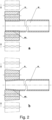
- Fig. 4 shows an embodiment of an axial radial mixing pre-forming rolling process according to the present invention, in which the pre-forming rolling wheel 81 is a smooth cylindrical rolling wheel ( Fig. 4a ) or a conical rolling wheel ( Fig. 4b ), and the effective length of the rolling wheel is less than the thread length of the pipe external thread product to be processed.
- a radial offset angle is provided between the rolling wheel 81 and the hollow blank.
- the rolling wheel 81 moves axially from the inner side 400 of the hollow blank to the end 401 of the hollow blank, while the rolling wheel 81 is radially fed to a certain process position to remain unchanged or synchronously radial feed or synchronously radially fed to a certain process position to remain unchanged, so that outer surface of part of the hollow blank to be provided with thread were processed into a cylindrical surface ( Fig. 4a ) or a conical surface ( Fig. 4b ) or a cylindrical conical mixing surface ( Fig. 4c ).
- the port outer diameter, taper and axial length of the formed cylindrical or conical or cylindrical conical mixing surfaces described in Figs. 2 , 3 and 4 can be provided as follows.
- Port outer diameter when used for rolling the cylindrical external pipe thread, the port outer diameter of the pre-formed blank is its corresponding median diameter of the cylindrical pipe external thread to be processed plus its tooth height by 5% to 90%, preferably by 20% to 85%.
- the port diameter of the pre-formed blank is equal to its corresponding median diameter of the conical pipe external thread to be processed plus its tooth height by 5% -90%, preferably plus its tooth height by 15% to 85%.
- the taper of the cylindrical surface formed by the pre-forming rolling is zero; the taper of the conical surface formed by the pre-forming rolling is generally from 2° to 5°, preferably from 2°30 "to 4°30".
- Axial length it is to be noted that the length thereof after being pre-formed rolling should be greater than or equal to the length of the subsequent thread product, preferably 1 to 3 pitch greater.
- the port outer diameter, taper and axial length thereof are further optimized according to the outer diameter, wall thickness, material of the hollow blank and the like as well as pipe thread profile and the thread length accuracy to be rolled subsequently.
- the stress of the blank section that is to be provided with the thread is partially released, and the non-roundness of the blank as well as the port diameter, taper and length (or height) of the cylindrical and conical surface reach the requirement of subsequent rolling pipe thread, which are more suitable for subsequent pipe thread forming rolling, and essential for the next step of the pipe thread forming rolling.
- the shape of the pre-forming rolling wheel of the present invention is not limited to three types of cylindrical rolling wheel, conical rolling wheel and conical cylindrical mixing wheel.
- the cylindrical rolling wheel and the conical rolling wheel may not only be the rolling wheel with smooth outside surface, can also be the rolling wheel with a thread on outer surface.
- the thread profile and thread pitch of the rolling wheel must be adapted to the thread profile and thread pitch of the external pipe thread to be processed in the external pipe thread forming rolling step, and the thread may be a complete thread or an incomplete tread with a complete tooth bottom and an incomplete tooth top; shapes and combination of the rolling wheel may also be provided by referring to patent WO2014056419A1 ;
- the pre-forming rolling wheel can be an annular rolling wheel and can also be a spiral rolling wheel.
- the axis of the pre-forming rolling wheel in order to be able to automatically feed the hollow blank in the pre-forming rolling step, has a certain deflection angle in vertical deviation from the axis of the hollow blank. The deflection angle is the same as the spiral rising angle of the pre-formed pipe thread.
- the pre-formed rolling wheel of the present invention utilizes a conical rolling wheel with a smooth surface, and in order to be able to automatically axial feed the hollow blank in the pre-forming rolling step, the axis of the pre-forming rolling wheel has a radial certain deflection angle in vertical deviation from the axis of the hollow blank.
- the axial feed for the pre-forming rolling is accomplished by an axial component incurred by the deflection angle.
- the pre-forming rolling process of the invention can only use a group of pre-forming rolling wheels to perform pre-forming rolling of hollow blank, and can also use a plurality of groups of pre-forming rolling wheels to repeatedly perform pre-forming rolling of the hollow blank. After repeated pre-rolling, the hollow blank is processed with thread rolling in accordance with the spirit of the present invention, so as to form the external pipe thread.
- Fig. 5 is a schematic view of the process of the present invention for further axial rolling to form a pipe external thread on a pre-rolled hollow blank.
- the pipe thread forming rolling wheel of the present invention comprises an external pipe thread forming portion through which a desired external pipe thread can be formed on a pre-rolled hollow blank by rolling.
- the external pipe thread rolling process of the present invention can be understood as according to the outer diameter, the wall thickness and the material of the hollow blank, as well as the subsequent pipe thread profile and the thread length accuracy, the portion of the hollow blank to be processed with the pipe thread is firstly performed in the radial or axial or axial radial direction, so that the cross-section of the rolled portion of the hollow blank is formed by rolling from the original random polygons into a regular polygon that can be controlled.
- the regular polygon conforms to the subsequent thread rolling requirements, and the non-roundness increase during pre-rolling will not exceed 10% of the original one.
- the invention also comprises, prior to the pre-forming rolling, a chamfering process for cutting the port of the cylindrical blank to be provided with thread using a chamfering tool with an axial length of 1 - 3 pitch, so that stability of the pipe thread rolling process can be further improved.
- the number of rolling wheels in two successive rolling steps must be different; that is, in the embodiment with two different process steps of pre-forming rolling and pipe thread forming rolling, the number of rolling wheels for pre-forming rolling and the number of rolling wheels for pipe thread forming rolling must be odd-even different.
- the number of rolling wheels for the pre-forming rolling process is an odd number
- the number of rolling wheels in the successive pipe thread forming rolling process must be an even number
- the number of rolling wheels for the pre-forming rolling process is even
- the number of rolling wheels in the successive pipe thread forming rolling process must be an odd number. In the case of even and odd numbers matching, it can significantly improve the yield of pipe thread forming rolling products by effectively controlling the port outer diameter, taper and axial length.
- the number of the pre-rolling wheels for correction is greater than or equal to 4, the number of the pipe thread forming rolling wheels is greater than or equal to 3, and the number of the pre-forming rolling wheels for correction is greater than that of the pipe thread forming rolling wheels.
- the pre-forming rolling wheels adopt a smooth rolling wheel axial rolling or axial radial mixing rolling.
- the length of the pre-forming rolling wheel must be greater than or equal to the axial length of the pipe thread product, preferably a pitch of 1 to 3 teeth larger.
- pre-rolling process in the pipe thread forming rolling process may be implemented by one pre-rolling or may be achieved by multiple rolling operations, for example, performing firstly, secondly, thirdly correcting pre-rolling, and then performing the pipe thread forming rolling, but the number of rolling wheels at two successive rolling steps must be different.
- the number of rolling wheels in two successive rolling steps must be different and mating with the smooth annual rolling wheels and its length.
- the rolling concept is not only beneficial for pipe thread forming rolling, but also for the roundness correcting, straightening and diameter shrinking of general hollow blank can also bring unexpected benefits.
- One possible application is to use multiple groups of rolling wheels for straightening, rounding and diameter shrinking of hollow blanks.
- the number of rolling wheels in successive rolling wheel groups can be provided to be different.
- the hollow blank in the prior and inferior multiple rolling process has a no-overlapped spiral, and a hollow blank with a unit cross-section of the non-irregular polygons is pre-rolled into a controllable regular polygons, during which part of the residual stress of the hollow blank is released, and the stress distribution is more uniform, while correcting non-roundness of the blank; then the regular polygons matches with the number of the follow-up correcting rolling wheels, making the original residual stress of the hollow blank is further released, thereby enhancing the quality of the roughness and the straightness of the hollow blank.
- This application is expected to replace the steel drawing technology current commonly used in steel pipe industry.
- Fig. 6 shows a schematic view of a pre-forming rolling head with only one rolling wheel disc 60 according to the present invention.
- the number of pre-forming rolling wheels 81 is five, and the five pre-forming rolling wheels are equally distributed around the processing axis of the hollow blank.
- the rolling head is rotated by the power motor via the pin 67, to form a structure of the rolling wheel 81 around the rolling wheel axle 83.
- Fig. 7 shows an embodiment of a plurality of pre-forming rolling wheels of the present invention.
- the pre-forming rolling wheel of the present invention may be a smooth-surfaced conical rolling wheel (7a), a cylindrical rolling wheel (7b) with a smooth annular rolling wheel and a rolling wheel axle formed integrally, a cylindrical rolling wheel (7c) in combination with cutting tools and a cylindrical rolling wheel (7d) which are integrally provided with the cutting tools, and so on.
- the hollow blank can be formed with the desired cylindrical or conical surface or cylindrical conical mixing surface at the same time to complete the hollow blank cutting, greatly improving the external pipe thread processing effectiveness.
- Figure 8 shows a schematic view of a rolling head corresponding to Fig.6 for forming pipe thread of the present invention, which includes a radial adjusting disc 76 and a rolling wheel disc 70, comprising four pipe thread forming rolling wheels 82.
- the four pipe thread forming rolling wheels are equally distributed around the processing axis of the hollow blank.
- the rolling head is rotated by the power motor via the pin 67 to form a structure of the rolling wheel 81 around the rolling wheel axle 83.
- the number of pre-forming rolling wheels is four, and the number of pipe thread forming rolling wheels is three.
- the number of pre-forming rolling wheels is six, and the number of pipe thread forming rolling wheels is three or five.
- the number of pre-forming rolling wheels is seven, and the number of pipe thread forming rolling wheels is four or six.
- the number of pre-forming rolling wheels is eight, and the number of pipe thread forming rolling wheels is five or seven.
- the number of pre-forming rolling wheels is nine, and the number of pipe thread forming rolling wheels is four, six or eight.
- the number of pre-forming rolling wheels and the number of pipe thread forming rolling wheels neither do not generally exceed 15, preferably 4, 5, 6, 7, 8 or 9;
- the number of pre-forming rolling wheels and the number of pipe thread forming rolling wheels neither do not generally exceed 19, preferably 4, 5, 6, 7, 8, 9, 10 or 11;
- the number of pre-forming rolling wheels and the number of pipe thread forming rolling wheels neither do not exceed 35, preferably 4, 5, 6, 7, 8, 9,10 , 11, 12, 13, 14, 15, 16, 17, 18, 19 or 20.
- the number of pre-forming rolling wheels and the number of pipe thread forming rolling wheels vary from 1 to 11, preferably 1, 3, 5 or 7.
- the different numbers may be the number that the number of the pre-forming rolling wheels is more or less than the number of the pipe thread forming rolling wheels. It is preferable that the number of the pre-forming rolling wheels is more and odd-even matched, so as to reduce the number of pipe forming rolling wheels and thereby reduce the difficulty of teeth alignment during pipe thread rolling.
- the relationship between the number, the taper and the length of the pre-forming rolling wheels, and the number of pipe thread forming rolling wheels, the length accuracy of the pipe thread products can be increased, decreased or matched according to the outer diameter, the wall thickness and the material, non-roundness of the hollow blank, rolling wheel diameter size, rolling wheel form, thread profile and rolling thread length accuracy requirements, and so on.
- the form of the pre-forming rolling wheels and the pipe thread forming rolling wheels is preferably a structure in which the rolling wheel and the rolling wheel axle are integrated. In this way, the number of rolling wheels can be effectively increased, which is beneficial to reduce the times of rolling in stages and prolonging the life of the rolling wheel.
- a preferable pre-forming rolling and pipe thread forming rolling head there is an axially free movable space 891 ( Figs. 6b and 8b ) between the rolling wheel and the rolling wheel seat, of course there is a certain radial movable space 892 ( Figs. 6b and 8b ).
- the movable space means that there is a space for the rolling wheel to move freely in the space.
- the axial movable space refers to the movable space of the rolling wheel in the axial direction of the rolling wheel axle.
- the axial distance of the axial movable space refers to the maximum distance for rolling wheel freely movable in the axial direction of the rolling wheel axle.
- the radial movable space refers to the movable space of the rolling wheel movable in the vertical direction of the processing axis along the hollow blank, and the radial distance of the radial movable space refers to the maximum distance of the pipe thread forming portion for the rolling wheel freely movable in the vertical direction of the processing axis of the hollow blank relative to the hollow blank to be processed.
- the rolling wheel and the rolling wheel seat or the rolling wheel axle and the rolling wheel seat may be a shaft hole free movable cooperation.
- Figs. 6b and 8b shows this type of cooperation, wherein Fig. 6b is a schematic structural view showing a pipe thread forming rolling head which only comprises a rolling wheel disc, wherein the rolling wheel and the rolling wheel axle are integrated;
- Fig. 8b shows a schematic structural view of a pre-forming rolling head including a rolling wheel disc and a adjusting disc.
- the rolling wheel and the rolling wheel axle are capable of freely cooperating with each other and show the free cooperation schematic view of the rolling wheel and the rolling wheel seat.
- the rolling wheel for forming pipe thread of the present invention may be an annular rolling wheel or a thread rolling wheel, and preferably an annular rolling wheel.
- the rolling wheel for forming pipe thread adopts an annular rolling wheel, there is a deflection angle of not more than 9 degrees in the vertical direction between the axis of rolling wheel for forming pipe thread and the axis of the workpiece processing working hole; meanwhile, in order to make each annular rolling wheel in the floating space achieve automatic teeth alignment in the most economical way, reduce damage of non-roundness by the rolling pressure on the hollow blank, the rolling wheel for forming pipe thread and its rolling wheel seat or rolling wheel axle for forming pipe thread and the rolling wheel seat can be a shaft hole cooperation with clearance for free movement; and each annual rolling wheel has a surface provided with initial part of the thread.
- the initial part of the thread refers to thread that firstly contacts the hollow blank when the annual rolling wheel performs the thread rolling process.
- the initial part of the thread is designed to have an equal extension or equal indent, and the specific design idea is as follows: It is assumed that the rolling head for forming pipe thread comprises a total of N annular rolling wheels, starting from one of the annular rolling wheels R i and the initial part of the thread of the next rolling wheel R i + 1 in the same clockwise direction is: a thread obtained based on the initial part of the thread of the rolling wheel R i to extend a distance of 1 / N pitch in accordance with the original thread profile and the pitch in the direction of the axis of the rolling wheel R i .
- Fig. 9 shows the position distribution of the initial part threads 821, 822, 823 and 824 of the respective annular rolling wheels in the rolling head for forming pipe thread including four annual rolling wheels according to the present invention.
- each annular rolling wheel is arranged in a row from left to right according to the order of clockwise arranged in the rolling head for forming pipe thread.
- the initial part thread 821 of the annular rolling wheel R 1 is shown as a complete annual threads starting from the tail of the tooth;
- the initial portion thread 822 of the rolling wheel R 2 is a thread obtained by extending the initial portion thread 821 of the rolling wheel R 1 by a distance of 1/4 pitch in the axial direction of the rolling wheel R 1 ;
- the initial portion thread 823 of the rolling wheel R 3 is a thread obtained by extending the initial portion thread 822 of the rolling wheel R 2 by a distance of 1/4 pitch in the axial direction of the rolling wheel R 2 ;
- the starting portion thread 824 of the rolling wheel R 4 is a thread obtained by extending the initial portion thread 823 of the rolling wheel R 3 by a distance of 1/4 pitch in the axial direction of the rolling wheel R 3 ;
- a starting portion thread 821 of the rolling wheel R 1 is a thread obtained by extending the
- the pre-forming rolling head and the rolling head for forming pipe thread according to the present invention may adopt the same or similar structural design.
- both the pre-forming rolling head and the rolling head for forming pipe thread can adopt a structural design with a rolling wheel disc and an adjusting disc or a structural design with only a rolling wheel disc.
- Figs. 10 to 16 describe in detail an embodiment of a universal rolling head structure of the present invention.
- Fig. 10 is a schematic structural view of an embodiment of an axially rolling head according to the present invention.
- Fig. 11 is a schematic view of the structure of a rolling wheel disc with six rolling wheels in the rolling head of FIG. 10 .
- Fig. 11a is a front view of the rolling wheel disc
- Fig. 1 1b is a side view of the rolling wheel disc.
- Figs. 11a is a front view of the rolling wheel disc
- Fig. 1 1b is a side view of the rolling wheel disc.
- the rolling head comprises front and rear rolling wheel discs (70A, 70B), a rolling wheel axle 83 matched with the radial groove 71 on the rolling wheel disc and rolling wheel 8 thereof, and a connecting pin 702 matched with the pin hole 701 on the rolling wheel disc; a workpiece processing hole 704 is provided at the center of the rolling wheel disc, and the mounting surface of the radial groove 71 of the rolling wheel disc to the rolling wheel is an inclined plane 703; the rolling wheel axle 83 is mounted on the radial groove 71 of rolling wheel disc by two end inclined planes 832a and 832b matched with the radial grooves 71 on the rolling wheel disc, and the shape and size of the groove 71 allows the rolling wheel axle 83 to be axially mounted.
- the two rolling wheel discs 70A and 70B are connected and fixed with each other through the connecting pin 702 of the rolling wheel disc to form the rolling head coaxially.
- a rolling time and position control adjusting rod 121 is provided at the end of the rolling head for controlling the pre-forming rolling time and the rolling axial length.
- Fig. 12 is a three-dimensional view of the structure of the rolling wheel axle in the rolling head of FIG. 10 and a schematic view of the radial offset angle ⁇ in the vertical direction provided between the axis of the rolling wheel axle and the axis of the hollow cylindrical blank.
- Fig. 12a is a front view of the rolling wheel axle
- Fig. 12b is a top view of the rolling wheel axle
- Fig. 12c is a side view of the rolling wheel axle.
- the two ends of the rolling wheel axle 83 each have upper and lower inclined planes 832a and 832b parallel to each other.
- the axis x' of the inclined plane thereof and the axial center line x of the rolling wheel axle form a radial setting angle ⁇ .
- the axis of the machining center is parallel to x 'and the angle between x and the plane formed by the machining center axis and x' is equal to the radial setting angle ⁇ .
- Fig. 12d clearly shows that when the rolling wheel is coaxially mounted on the center of the rolling wheel axle, the axis of rolling wheel forms a radial setting angle ⁇ with the inclined planes 832a, 832b.
- the axial of the installed rolling wheel axle and the axial of the hollow blank forms a spiral rising angle ⁇ , and when the hollow blank and the rolling wheel make mutual contact and rotation with each other, the hollow blank can be moved axially.
- the greater the spiral rising angle ⁇ is, generally no more than 9 degrees, the faster the hollow blank moves axially.
- the radial setting angle ⁇ is preferably less than 5 degrees for steel pipes below 2 inches; and the radial setting angle ⁇ is preferably less than 3 degrees for those with 2 to 6 inches.
- Fig. 13 is an embodiment further comprising a rolling head for axial rolling of the adjusting disk on the basis of Fig. 10 according to the present invention.
- Fig. 14 is a structural diagram of the rolling wheel disc in Fig. 13.
- Fig. 14a is a front view of the rolling wheel disc
- Fig. 14b is a side view of the rolling wheel disc.
- the rolling wheel disc of Fig. 14 is basically similar in structure to the rolling wheel disc of Fig. 11 , except the shape of the radial groove 71.
- the radial groove 71 of the rolling wheel disc in Fig. 14 is a combination of a cylinder and a cuboid.
- the cylinder exists for the purpose of mounting the rolling wheel axle with a cylindrical end.
- the radial groove 71 of the rolling wheel disc in Fig. 11 is an approximately rectangular structure, cooperating with the rolling wheel axle with an approximating rectangular end. Other structures are the same, which will not be repeated here.
- Fig. 15 is a schematic structural view of the adjusting disc in the rolling head of Fig. 13 .
- Fig. 15a is a front view of the adjusting disc structure
- Fig. 15b is a side view of the adjusting disc structure.
- the radial adjusting device comprises a front and back adjusting disc 76A and 76B and a fixed connecting pin 763 matched with the pin hole 761 on the adjusting disc.
- the center of the adjusting disc is provided with a workpiece processing working hole 764 matched with the rolling wheel disc and a positioning and mounting blind hole 766 in the adjusting disc which is matched with the rolling wheel disc;
- the adjusting disc 76 is coaxially mounted front and rear respectively on the outside of the rolling wheel disc through the positioning blind hole 766 of the adjusting disc and are connected to each other by the adjusting disc pin 763 and to form a shaft hole cooperation with the adjusting disc pin; As shown in Fig.
- a sliding piece 836 is mounted on the two ends 833 of the rolling wheel axle and slides in the arc-shape groove 762 of the adjusting disc, so that the rolling wheel axle 83 moves radially in the radial groove 71 of the rolling wheel disc 70 to form a rolling head whose radial position is adjustable with respect to the rolling wheel.
- a rolling position photo-sensing control adjusting rod 122 is provided on the side where the rolling head is finished rolling for controlling the rolling time and the rolling length.
- the pre-forming rolling time controlled by the photo-sensing control adjusting rod 121 in FIG. 10 and the thread rolling time controlled by the control adjusting rod 122 in Fig. 13 must be matched reasonably in order to roll out the qualified pipe external thread product.
- the power motor is rotated by the rolling head driven by the pin 77 so that the rolling wheel 8 surrounds the rolling wheel axle 83.
- Fig. 16 is a three-dimensional view of the structure of the rolling wheel axle and its radial offset angle according to the present invention.
- Fig. 16a is a front view of the rolling wheel axle
- Fig. 16b is a top view of the rolling wheel axle
- Fig. 16c is a side view of the rolling wheel axle
- Fig. 16d is a schematic view showing the angle ⁇ provided in the vertical direction between the rolling wheel axis and the hollow cylindrical blank axis.
- Fig. 17a is a schematic view of the structure of a rolling wheel according to the present invention.
- the rolling wheel includes a guiding-in portion and a rolling portion.
- the taper of the pre-forming rolling portion on the rolling wheel is 2° to 5°.
- the taper size of the pre-forming rolling portion is determined according to the essence of the present invention, preferably 2°30 " ⁇ 4°30".
- the angle of the guiding-in can be generally 13°; the rolling portion for pipe thread has a pipe thread taper of 1:16.
- Fig. 17b is a schematic view of the rolling wheel, a needle bearing cooperating with a rolling wheel axle according to the present invention.
- the cooperation of the rolling wheel 8 and the needle bearing 831 mainly reduces the rotational friction force of the rolling wheel.
- the rolling wheel 8 is freely mounted on the rolling wheel axle 83 through needle bearings 831.
- the rolling wheel shaft 83 and the rolling wheel 8 can also be matched with each other by balls, aligning or other bearings;
- Figure 17c is a cross-sectional view of a sliding piece that mates with a rolling wheel axle.
- the two cylindrical ends 833 of the rolling wheel axle 83 are mounted (position adjusting) in the holes of the sliding piece 836 to form a shaft hole fitting; the sliding piece 836 is installed in the arc-shaped slot 762 ( Fig.15a )of the adjusting disc, forming a cylinder and circular arc cooperation.
- a rolling position control adjusting rod 122 is provided at the end of the rolling head for controlling the rolling time and the rolling length.
- the rolling wheel disc is movably fixed on the apparatus rack (not shown) by a rolling head frame 68 (as shown in FIG. 18 ).
- the adjusting disc is rotated with respect to the rolling wheel disc.
- a cam device is provided on the adjusting disc (not shown in the fig.). The cam curve controls the radial distance adjustment of the rolling wheel and the radial opening of the rolling head.
- a position relative rotation detecting device 123 (also not shown in the fig.) can also be arranged between the rolling wheel disc and the adjusting disc for numerical control purpose.
- Fig. 18 is a rolling head embodiment that can be passed through by the improved hollow blank on the basis of Fig. 13 rolling in the axial direction.
- Pipe thread rolling time control and pre-forming rolling time and rolling wheel radial position must be a reasonable match.
- the length of the pre-forming conical or the cylindrical surface or the axial radial mixing surface should be greater than or equal to the length of the pipe thread to be rolled, preferably 1 to 3 teeth greater, more preferably 2 teeth pitch greater.
- the setting of the radial position determines the outer diameter of the pre-forming hollow blank end port.
- the frame structure 68 of the rolling head of Fig. 18 has holes (not shown) and pins (not shown) on the side end thereof.
- the frame structure 68 or the side ends of the rolling head are sleeved on the hole of the rolling device carriage, forming a floating connection, so as to achieve self-centering of the rolling module seat and the hollow blank.
- Fig. 19 shows a schematic structural view of an embodiment of a manual axial radial pre-forming rolling head of the present invention.
- the rolling head comprises: an upper rolling wheel seat plate 60A2, a threaded upper rolling wheel seat push rod 60A1, a torque amplifying gear group 69, a screw nut 696, and a rotation handle 691.
- the upper rolling wheel seat plate 60A2 is fixedly connected to the rolling wheel seat 60A and sleeved on the guiding column 611 to form shaft-hole cooperation.
- One end of the upper rolling wheel seat pushrod 60A1 is against and fixed to the upper rolling seat plate 60A2, and the other end cooperates with the screw nut 696, and cooperates with the output gear bearing bore in the torque amplification gear group coaxially.
- the input shaft of the torque amplifying gear group 69 is fixedly connected with the rotation handle 691.
- the lower rolling wheel seat plate 60B2 and the lower rolling wheel seat 60B are fixedly connected and sleeved and fixed on the guide column 611.
- the rotation handle 691 drives the gear input shaft to rotate
- the upper rolling wheel seat pushrod 60A1 is driven to move up and down through the torque amplifying gear group 69 and the screw nut 696.
- the hollow cylindrical blank 40 is engaged and rotated by the rolling wheel 81, the radial feed rolling of the rolling wheel is completed.
- the rolling wheel 81 is arranged so that its axial direction and the hollow blank have a deflection angle ⁇ in the vertical direction (radial direction), the radial rolling becomes an axial radial mixing rolling.
- the rolling wheel is a pre-forming rolling wheel with a cutting blade, the rolling head can also complete the cutting process of the hollow cylindrical blank.
- the rolling head of Fig. 19 has a hole 601 and a number of pins (not shown) on the side end of the frame structure.
- the side end of the rolling head is connected to the hole on the roller carriage by the pins to form a floating connection, thereby achieving self-centering of the rolling module seat and the hollow blank.
- the self-centering design of the rolling head and the hollow blank of Figs. 18, 19 and 20 by the floating connection of the shaft hole clearance relative to the rolling head and the base actually solves the problem of the manufacturing and assembling precision of the apparatus and the hollow blank and the concentricity of the actual mounting of the blank, which is also crucial to the rolling.
- the size of the shaft hole clearance depends on the design and manufacturing precision of the device, preferably no more than +/- 1 mm.
- the structure of the rolling head can also be properly arranged and modified according to the corresponding rolling head device involved in the following patents listed as follows: US5699691A , US3058196A , EP282889A2 , US3452567A , US3058196A , US20060162411A1 , JP10034270A , JP10244340A , JP2003126937A , JP9327742A , CN100542735C , CN2555962Y , CN103264128A , CN103286245A , SU1344479A1 , US20120011912A1 , US4617816A , US4785649A , US5870918A , GB1150525A , JP1273637A , SU703197A1 .
- the pre-forming rolling head and the rolling head for forming pipe thread according to the present invention may be separate or combined into one body. When the two are combined into one, the process can be effectively saved, and the external pipe thread to be processed is formed by rolling sequentially.
- the overall design is more compact and convenient for transportation and installation.
- Fig. 20 shows a schematic view of the structure of a rolling process module in which a pre-forming rolling head 6 and a rolling head 7 for forming pipe thread are combined into one body according to the present invention.
- a pre-forming rolling head 6 with five rolling wheels 81 and on the right-hand a rolling head for7 forming pipe thread with four rolling wheels 82.
- Structure of the pre-forming rolling head 6 is similar to that of FIG. 18
- the pipe thread forming rolling head 7 adopts a rolling head structure similar to that in Fig. 13 .
- the mounting surface of radial grooves (71) in the rolling heads of the rolling wheel (8) may be an inclined plane (703) or a conventional plane (as shown in Fig. 6 or Fig. 8 ).
- the specific structural design is not limited to the rolling head structure disclosed in the present embodiment.
- a relative rotational position angle detecting device 123 is provided between the rolling wheel disc and the adjusting disc of the pre-forming rolling head 6 and the pipe thread forming rolling head 7, and can be determined according to the variation of the blank diameter, the wall thickness and the materials and actual requirements of the pipe thread products.
- the radial position of the rolling wheel of the pre-forming rolling head should be reduced to no more than 0.5 mm.
- the radial position of the rolling wheel of the pre-forming rolling head should be enlarged by no more than 0.5 mm.
- the length of the pre-forming rolling surface controlled by the rolling time is equal to or greater than that of the pipe thread product, preferably greater by the pitch length of 1 to 3 teeth, more preferably the pitch length of 2 teeth.
- the pre-forming rolling head 6 and the pipe thread forming rolling head 7 are connected with each other by a pin to ensure that the pre-forming rolling head 6 and the pipe thread forming rolling head 7 are disposed coaxially with the hollow blank to be processed.
- the workpiece passes through the pre-forming rolling head, directly into the pipe thread rolling.
- the hollow blank 40 enters the rolling head from the left and number reference 121 and 122 are used to mark the control adjusting rod with the photoelectric sensing device which controls the pre-forming rolling time and sequence.
- the control adjusting rod 121 drives the photoelectric sensing device to work, and the adjusting disc 66 is started to turn in the reverse direction to disengage the hollow cylindrical blank from rolling wheel 81, to complete the pre-forming rolling and come into the right pipe thread forming rolling process.
- the photoelectric sensing device When its head contact the control adjusting rod 122, the photoelectric sensing device operates and starts the adjusting disc 76 to rotate in opposite direction to open, so that the hollow cylindrical blank is disengaged from the rolling wheel 81, to complete the pipe thread rolling, and the process is similar to the foregoing, which are not repeated here.
- Fig. 21 shows a schematic structural view of a single head pre-forming rolling and pipe thread forming rolling apparatus comprising a rolling head shown in Figs. 13 and 18 with hollow blank rotating. Except for the design of the rolling head, the design of the other components is consistent with the single head pipe thread forming rolling device with the hollow blank rotating as disclosed in the patent WO2014056419A1 .
- the main structure includes a base 1, a power motor 22, a work clamping device 3, a motor control device 20, and a transmission 21 that couples the power motor to the hollow cylinder blank clamping device or the rolling head.
- the base 1 is provided with the power motor 22, the motor control device 20 and the clamping device 3 for clamping the hollow cylindrical blank to be processed. Under the control of the motor control device 20, the power motor 22 generates a relative rolling and rotational movement of the rolling wheel and the hollow blank 40 clamped by the clamping device 3 through the transmission device 21.
- Fig. 22 is a schematic structural view of a double-ended external pipe thread rolling apparatus which includes two groups of integrated rolling process modules of Fig. 20 . Left and right sides in the figure are provided with the hollow blank pre-forming rolling head 6 and the pipe thread forming rolling head 7. The axial and radial mode of operation of the left and right four rolling heads, the basic configuration and function of the device are the same as that in Figs. 20 and 21 , which are not repeated here. According to the need, a chamfering device 9 can be provided to complete the chamfer function.
- Figs. 23-31 are distribution structures of four embodiments of the rotary rolling process module according to the present invention.
- the rolling head is driven to rotate by a power (servo) motor, through mechanical transmission such as a reduction gear box, a worm gear and the like.
- a pre-forming rolling head, a pipe thread forming rolling head, and other processing tools such as a nozzle port external chamfering machining tool, an inner hole correction tool, a taper correction tools and thread surface grinding or heat treatment tools etc., are installed in the rolling head through the keyway 67 or 77 in Fig. 10 or Fig. 13 .
- This processing method that a hollow blank is fixed, and the rolling head rotate is suitable for external pipe thread processing of long pipe, especially, it is very meaningful for the oil casing pipe external thread processing.
- the size control of the hole is very important.
- we can machine the conic surface by cutting the taper and then roll the external pipe thread without rolling the cylinder or conical surface.
- the structure of the pre-forming rolling head and the pipe thread rolling head is similar to that shown in FIG. 13 , which will not be repeated here.
- Fig. 23 is a schematic structural view of an embodiment of a rolling process module according to the present invention.
- the pre-forming rolling head and pipe thread forming rolling head in figure was front and rear arranged.
- Two (servo) power motors 22 are respectively installed above the middle of the pre-forming rolling head and the pipe thread forming rolling head, and the rotational power is respectively transmitted to the front and rear worm wheels 636 and 736 via the transmission device 21 and the worms 6311 and 6312, and the worm wheels 636 and 736 respectively drives the pre-forming rolling heads 6 (not shown in the figure) and the pipe forming rolling heads 7 (not shown in the figure) on the rolling head seat to rotate through the rolling head seats65 and 75.
- a (servo) power motor whose transmission device 21 controls the worm gear 636 and 736 to transfer correction and the rotation of the pipe thread forming rolling head via the worm gears 6311 and 6312, respectively.
- Fig. 24 shows a schematic structural view of a pipe thread forming rolling device including the rolling process module of Fig. 23 .
- the pre-forming rolling head and the pipe thread forming rolling head are arranged in a front-to-back horizontal arrangement.
- the power motor rotates the rolling head through the transmission device 21 and the worm 631.
- the pre-forming rolling head 6 and the pipe thread forming rolling head 7 are driven to rotate by the transmission device 21, the worm 631 and the worm gears 636 and 736, and the workpiece clamping device 3 installed in the sliding seat 10 is gradually axial fed to the left along the horizontal (left and right) parallel guide rails 11 under the action of rolling axial force, and performs rolling so as to complete the pre-forming rolling.
- the photoelectric sensing device 12 controls motor reversal, rolling head 6 exits, the workpiece clamping device 3 exits to the right axial to complete the pre-forming rolling station. Subsequently, manually turn the rolling head group 180 degrees, so that the pipe thread forming rolling head 7 come into the station, and the semi-finished blank through pre-forming rolling is axially squeezed into the pipe thread forming rolling head 7 to complete the pipe thread axis forming rolling.
- Fig. 25 is a schematic structural view of another embodiment of a rolling process module according to the present invention.
- Pre-forming rolling head and pipe thread forming rolling head in figure are left and right arranged.
- the power motor is meshed with gear 21 to decelerate and amplify torque output power.
- a (servo) power motor 22 is installed above the center of the pre-forming rolling head and the pipe thread forming rolling head, and delivers the rotational power to worm gears 636 and 736 on the left and right sides respectively via a transmission device 21 and a worm 631.
- the worm gears 636 and 736, respectively pass through the rolling head seats 65, 75 therein to rotate the pre-forming rolling head (not shown) and the pipe thread forming rolling head (not shown) mounted on the rolling head seat, respectively.
- Fig. 26 is a schematic structural view of a pipe thread forming rolling device that includes another rolling process module of the rolling head shown in Fig. 10 , Fig. 13 , or Fig. 18 .
- the two rolling heads 6 and 7 are arranged horizontally on the left and right, with an outer or inner circular chamfering device 9 therebetween.
- the hollow blank 40 is clamped and fixed by the workpiece clamping device 3, the chamfering device 9 is coaxial with the hollow blank 40.
- the two rolling heads 6 and 7 of the present invention and the chamfering device 9 are simultaneously rotated by the transmission device 21, and the chamfering device 9 on the sliding seat 9 mounted on the horizontal plane guide rail 111 is axially fed to the chamfering station, and firstly perform external chamfering process of the hollow blank, and the photoelectric sensing device 12 controls the motor to complete the chamfering process and to reverse, and the sliding seat 102 come back to the starting position;
- the second step as shown in Fig.
- the pre-forming rolling head 6 on the sliding seat 103 moves forward along the front-back planar guide rail 112 until its axis is concentric with axis of the hollow blank, and then the pre-forming rolling head 6 moves axially along the right and left horizontal guide rail 111 to pre-forming station, using axial component to axial pre-form the hollow blank 40 to complete the pre-forming rolling, and the photoelectric sensing device 12 controls the motor reversal, and the rolling head 6 exits;
- the sliding seat 103 moves along front and back planar guide rail 112 so that the axis of the rolling head 7 is concentric with the axis of the pre-formed hollow blank 40, not shown in the figure.
- the rolling head 7 moves along the horizontal left-right guide rail 111 to the rolling thread station, and uses axial component to perform thread rolling process of the hollow blank to complete pipe thread rolling, then the photoelectric sensing device 12 controls the motor reversal, and the rolling head 7 exits, the rolling process is completed.
- the plane movement (front, rear, left and right) of sliding seats 102 and 103 may be performed numerically or manually.
- Photoelectric sensing devices can be installed on each process, such as external chamfering, pre-forming and thread rolling.
- the processing time and speed are controlled by control system and the spirit of the present invention. It should be pointed out that it is preferable to adjust the rolling wheel with radial position which can be adjustable according to the outer diameter of the steel blank, its non-roundness, wall thickness and material as well as the subsequent pipe thread requirements; Of course, the number of the rolling wheel in before and after process must be odd and even matching and the total number of rolling wheel.
- Fig. 27 is a schematic structural view of still another embodiment of a rolling process module according to the present invention.
- the pre-forming rolling head and pipe thread forming rolling head in figure are L-shaped configured.
- a (servo) power motor 22 is mounted above the pre-forming rolling head and the pipe thread forming rolling head and transmits rotational power to two groups of the worm gears 636 and 736, respectively, through the transmission device 21 and the worm 631, and then worm gears 636 and 736 pass through the rolling head seats 65, 75 therein to respectively drive the pre-forming rolling head (not shown) and the pipe thread forming rolling head (not shown) mounted on the rolling head seat to rotate.
- Fig. 28 is a further illustration of pre-forming rolling cylindrical blank using the rolling head in L-shaped arrangement of Fig. 27 .
- the movement of the cylindrical blank workpiece and feeding method of rolling head are similar to the foregoing, which will not be repeated here.
- Fig. 29 is an explanatory view of the pipe thread further processed in Fig. 28 .
- the rolling head group is rotated by 90 degrees under the action of external force and the pipe external thread processing is continued.
- the movement of cylindrical blank workpiece and feeding method of rolling head are similar to the foregoing, which are not repeated here.
- Fig. 30 is a schematic structural view of still another embodiment of a rolling process module according to the present invention.
- the pre-forming rolling head, pipe thread forming rolling head and other processing group was arranged in a cross shape.
- a (servo) power motor 22 is mounted above the center of the pre-forming rolling head, pipe thread forming rolling head and other process groups, transmitting the rotational power to the four-sided worm gears 636, 736, 936, and 1436 through the transmission 21 and the worm 631, respectively.
- the worm gears in turn drive the pre-forming rolling head (not shown) and pipe thread rolling head mounted on the rolling head seat through their respective rolling head seats 65, 75, 95 and 145, respectively (Not shown) to rotate, and subsequent auxiliary machining tools (not shown in the figures, which can be hole, cylindrical, taper or thread surface machined, etc.) to work.
- auxiliary machining tools not shown in the figures, which can be hole, cylindrical, taper or thread surface machined, etc.
- the rolling head group rotates 90 degrees each time, and perform a variety of processing, such as: bore correction 14, end port processing 15, thread induction heat treatment, thread grinding and thread coating processing, and so on, and its work method is similar to the prior art, the and the method that the processing tools are installed on the rolling head seat 1436 and 1536 are in the same manner as described above, which will not be repeated here.
- Fig. 31 is a schematic structural view of a double-ended conical pipe thread forming rolling production line according to the present invention.
- the hollow blank pre-forming rolling head 6 and pipe thread forming rolling head 7 are arranged with the hollow blank pre-forming rolling head 6 and pipe thread forming rolling head 7 in front and rear respectively, which separated the pre-forming rolling and pipe thread forming rolling as A station and B station.
- the hollow blank 40 is locked and rotated at a set rotational speed by a power motor (not shown)
- the two left and right first pre-forming rolling head 6 respectively start to pre-forming rolling at 400, i.e. the initial part of the pipe thread to be processed, and then perform thread rolling from the outer to the position 401, i.e. the tail of the pipe thread to be processed, so as to complete the first pre-forming rolling, and the workpiece is released, the pre-forming rolling head 6 exits outward.
- the robot arm moves the workpiece from the A station to the B station, and lock them again and rotate it by the power motor (not shown) at the set rotation speed.
- the pipe thread forming rolling head 7 are respectively start round correcting rolling at 420, i.e. the initial part of the pipe thread to be processed, and then perform thread rolling from the outer to the position 421, i.e. the tail of the pipe thread to be processed, so as to complete the pre-forming rolling external thread again, and the workpiece is released, the pipe thread rolling head 7 exits outward.
- the robot arm moves the external pipe thread product from the station B to the next station, and rolling process for the double-ended conical external pipe thread product is completed. It can also achieve rolling external pipe thread product when changing the pre-forming rolling process into stamping or extrusion process in station A, but the process and product defects have been described above, which will not be repeated here.
- the existing external pipe thread rolling process adopts a large-tonnage axial stamping device to first process a 1:16 conical surface 425; as shown in Fig. 1c , the pipe thread forming rolling wheel 80 is then used to perform axial rolling process from the pipe port 420, i.e. the initial part 460 of the pipe external thread to be processed, to the position 421, i.e. the tail 461 of the pipe thread to be processed, so as to complete the process of the external pipe thread product 46.
- This rolling process must have a large tonnage of axial stamping or radial extrusion apparatus, dedicated to the processing of the conical surface 425.
- the pipe material especially the welded pipe weld 461 at the intersection of the original outer diameter 423 of the steel pipe and the conical surface, causes recessive and dominant damage to the rolling external pipe thread products and leave security risks.
- the hollow blank 40 is manufactured by the pre-forming rolling method of the present invention by using a conical smooth rolling wheel 81, so as to perform conical pre-forming rolling, and steel pipe residual stress is partially released.
- a conical smooth rolling wheel 81 As the port medium diameter and tooth height of DN32 55 degrees national standard pipe thread is 39.64 mm, 1.479 mm.
- the material of the hollow blank is Q235, which belongs to medium-low-carbon steel.
- the rolling head is used to start pre-forming rolling at 400, i.e.
- the initial part 420 of the pipe external thread to be processed and then axial pre-forming rolls to 401,i.e., the tail part 421 of the pipe external thread to be processed, using the axial component force generated by the deflection angle of the rolling wheel 81 on the rolling head and the hollow blank 40 during the rolling process so as to form the conical surface 425; afterwards, the blank formed with the conical surface 425 enters the axial pipe thread forming rolling process.
- the rounding correction and external thread forming process are produced under the action of the rounding correction external pipe forming rolling wheel 82.
- the hollow blank 40 with standard D32 steel pipe external outer diameter forms an acceptable external pipe threads at 480 and 481.
- the structure of the apparatus is greatly simplified and portable, laying a foundation for the popularization of rolling process for external pipe thread.
- the recessive and dominant failure of the pipe material particularly at the intersection of the standard pipe outer diameter and conical surface by the stamping pressure on conical formed surface is avoided, and greatly reduces the potential safety hazard caused by the existing rolling technology.
- the problem that galvanized coating is damaged and the steel pipe is thinned, and other issues, is avoided, and the rolling failure caused by deformation of hollow blank due to the rolling out the conical surface or diameter reduction into a cylindrical surface by the radial three rolling wheels is also avoided.
- DN32 of the aforementioned standard steel pipe outer diameter blank 40 is placed in the clamping device 3 and clamped, the motor switch 20 is opened to rotate the hollow blank 40, and the floating rolling material cutting device 5 is manually fed according to the process in radial direction, roll and cut off the hollow blank 40 from length of 6000 mm to the desired length of 2750 mm, manually rotate in opposite direction and loose the rolling material cutting device 5, and turn off the motor switch 20, so as to complete the processing in the cutting station.
- the pre-forming rolling device 6 is manually fed axially by the crank handle 101 to the machining position 400 which is the position of the initial part 420 of the external pipe thread to be processed.
- the rolling wheel 81 in the floating pre-forming rolling device 6 is manually moved to axially contact processing position 400 for the hollow blank 40.
- the hollow cylindrical blank 40 is guided in and was axial pre-forming rolling fed using the deflection angle between the pre-forming rolling wheel with smooth conical surface and the hollow blank 40.
- the photoelectric sensing device controls the adjusting contact rod 121 to work and the motor rotates in the reverse direction, and then manually moves the radial position control rod on the pre-forming rolling control panel (not shown), so that the rolling wheel 6 in the pre-forming rolling device is separated from the hollow blank 40, and then continue to rotate the handle 101 in the same direction, and manually move the rolling wheel 82 in floating pipe thread forming rolling floating device 7 to axially contact with the processing position 420 of conical blank 40.
- the conical blank is guided in and axially fed to correct round and pipe thread forming rolling via the guided deflection angle between spiral rising angle and the hollow blank 40.
- the photoelectric sensing device controls the adjusting contact rod 122 to work and the motor rotates in the reverse direction, and then manually moves the control rod on the pipe thread forming rolling control panel (not shown), so that the rolling device is separated from the pipe external thread product, and the rolling process is completed.
- the floating chamfering device can be used together.
- the cutting point of pre-forming rolling wheel and pipe thread forming rolling wheel can be started from the initial portion of the external pipe thread, and it can be started from the tail of the effective thread or the tail of full thread or other non-threadable end of the full thread to start rolling and cutting toward the initial portion to complete the thread rolling.
- the rolling wheel is not completely radially fed into place and axially rolled, we can equate that the rolling wheel on the rolling head is actually an incomplete thread.
- Each rolling head can be arranged horizontally or vertically. It is particularly pointed out that the pre-forming rolling process of the present invention can be simplified and omitted when the cylindrical blank is completed with a perfect non-roundness by using the existing stamping process and directly enters process of correcting roundness and pipe thread forming rolling.
- each rolling wheel can also self-rotate with its own power around the axis of the rolling wheel relative to the hollow blank.
- steel pipe such as carbon steel pipe, stainless steel pipe, copper pipe, titanium steel pipe and special alloy steel pipe, etc
- different sizes of steel pipe such as 3/8 inches and 6 inches above, or other non-standard outer diameter hollow blank
- the rolling wheel length and external pipe thread can be determined according to the rolling method disclosed in the present invention.
- the rolling method of the present invention is not only suitable for hollow blank.
Landscapes
- Engineering & Computer Science (AREA)
- Mechanical Engineering (AREA)
- Metal Rolling (AREA)
- Forging (AREA)
Claims (10)
- Procédé pour laminer un filet de tuyau externe, comprenant l'étape consistant à laminer une ébauche creuse (4, 40, 42) par un premier groupe de roues de laminage et un second groupe de roues de laminage tour à tour, dans lequel le premier groupe de roues de laminage comprend au moins quatre premières roues de laminage (8, 81) agencées de manière circonférentielle et le second groupe de roues de laminage comprend au moins trois secondes roues de laminage (8, 82) agencées de manière circonférentielle, les premières roues de laminage (8, 81) sont des roues de laminage avec une surface externe lisse, et les secondes roues de laminage (8, 82) ont une partie de formage de filet de tuyau externe (821, 822, 823, 824), et le procédé comprend les étapes suivantes consistant à :étape 1 : le premier groupe de roues de laminage procède au laminage de la surface externe de l'ébauche creuse (4, 40, 42) en une surface cylindrique (424), une surface conique (425) ou une surface mixte cylindrique conique ;étape 2 : le second groupe de roues de laminage procède à nouveau au laminage de la surface externe de l'ébauche creuse (4, 40, 42) traitée à l'étape 1, afin de former le filet de tuyau externe par laminage ;dans lequel le nombre de premières roues de laminage (8, 81) dans le premier groupe de roues de laminage et le nombre de secondes roues de laminage (8, 82) dans le second groupe de roues de laminage est impairpair, c'est-à-dire que l'un est un nombre impair et l'autre est un nombre pair.
- Procédé pour laminer un filet de tuyau externe selon la revendication 1, dans lequel les premières roues de laminage (8, 81) ont une ou plusieurs des caractéristiques suivantes :a) les premières roues de laminage (8, 81) sont des roues de laminage cylindriques ou coniques avec une surface externe lisse ;b) il y a un angle de déflexion (δ) non supérieur à 9 degrés dans la direction verticale entre l'axe (X) des premières roues de laminage (8) et l'axe (X') de l'ébauche creuse (4, 40, 42) à traiter ;c) il y a un espace de mouvement libre entre les roues de laminage (8) et les sièges de roue de laminage sur lesquels les roues de laminage (8) sont positionnées.
- Procédé pour laminer un filet de tuyau externe selon la revendication 1, dans lequel le processus de laminage du premier groupe de roues de laminage et du second groupe de roues de laminage est sélectionné parmi l'une des coopérations suivantes :a) le processus de laminage du premier groupe de roues de laminage et du second groupe de roues de laminage est le laminage axial ;b) le processus de laminage du premier groupe de roues de laminage est le laminage radial, et le processus de laminage du second groupe de roues de laminage est le laminage axial ;c) le processus de laminage du premier groupe de roues de laminage est le laminage hybride axial radial, et le processus de laminage du second groupe de roues de laminage est le laminage axial.
- Module de traitement pour laminer un filet de tuyau externe comprenant une première tête de laminage (7) et une seconde tête de laminage (7), dans lequel la première tête de laminage comprend au moins quatre premières roues de laminage (8) agencées de manière circonférentielle ; la première roue de laminage (8) est une roue de laminage avec une surface externe lisse ; etdans lequel la seconde tête de laminage (7) comprend au moins trois secondes roues de laminage (8) agencées de manière circonférentielle ayant une partie de formage de filet de tuyau externe (821, 822, 823, 824) ; etdans lequel le nombre de premières roues de laminage (8) dans le premier groupe de roues de laminage et le nombre de secondes roues de laminage (8) dans le second groupe de roues de laminage est impair - pair, c'est-à-dire qu'un est un nombre impair et l'autre est un nombre pair.
- Module de traitement selon la revendication 4, dans lequel le nombre de premières roues de laminage (8) dans le premier groupe de roues de laminage est supérieur au nombre de secondes roues de laminage (8) dans le second groupe de roues de laminage.
- Module de traitement selon la revendication 4, dans lequel la première tête de laminage et la seconde tête de laminage sont combinées en un corps et la première tête de laminage et la seconde tête de laminage sont agencées de manière coaxiale avec l'ébauche creuse (4, 40, 42) à traiter,
dans lequel la première tête de laminage est agencée du côté à proximité du début du filet de tuyau externe traité. - Module de traitement pour laminer un filet de tuyau externe selon la revendication 4,dans lequel la première tête de laminage (7) comprend un premier disque de roue de laminage (70A) correspondant, un second disque de roue de laminage (70B) et une broche de raccordement (763), et le premier disque de roue de laminage et le second disque de roue de laminage sont prévus avec des rainures radiales (71), des trous de traitement de pièce à usiner (704) et des trous de broche (701) correspondants les uns aux autres, et la roue de laminage (8) coopère avec les rainures radiales (71) sur le premier disque de roue de laminage (70A) et le second disque de roue de laminage (70B) via l'arbre de roue de laminage (83), et la surface de montage de la rainure radiale (71) et de la roue de laminage (8) est un plan incliné (703) ; le premier disque de roue de laminage (70A) et le second disque de roue de laminage (70B) sont fixement raccordés entre eux par une broche de raccordement (763) qui correspond au trou de broche (701), formés de manière coaxiale en tant que tête de laminage, et les deux extrémités de l'arbre de roue de laminage (83) sont prévues avec des plans inclinés (832a, 832b) parallèles entre eux et l'essieu de roue de laminage (83) est monté sur une rainure radiale (71) du disque de roue de laminage par le biais des plans inclinés (832a, 832b) ; l'axe X de la roue de laminage forme un angle inclus avec les plans inclinés (832a, 832b) et l'angle inclus est inférieur à 9 degrés, de préférence inférieur à 3 degrés, et la première tête de laminage comprend en outre une tige d'ajustement de commande ; la tige d'ajustement de commande est installée sur le dessus ou au niveau de la queue de la tête de laminage du côté où le laminage est terminé ;dans lequel la seconde tête de laminage comprend également un premier disque de roue de laminage (76A) correspondant, un second disque de roue de laminage (76B) et une broche de raccordement (763) ; le premier disque de roue de laminage et le second disque de roue de laminage sont prévus avec des rainures radiales (71), des trous de traitement de pièce à usiner (704) et des trous de broche (701) correspondant les uns aux autres ; la roue de laminage coopère avec les rainures radiales (71) sur le premier disque de roue de laminage et le second disque de roue de laminage via son arbre de roue de laminage (83) ; le premier disque de roue de laminage et le second disque de roue de laminage sont fixement raccordés entre eux par une broche de raccordement (763) qui correspond au trou de broche (701), formés de manière coaxiale en tant que tête de laminage ; la seconde tête de laminage comprend en outre une tige d'ajustement de commande (122) ; la tige d'ajustement de commande est installée sur le dessus ou au niveau de la queue de la seconde tête de laminage du côté où le laminage est terminé ;dans lequel la première tête de laminage et la seconde tête de laminage sont agencées de manière coaxiale ensemble par une broche.
- Module de traitement pour laminer un filet de tuyau externe selon la revendication 7, dans lequel la première tête de laminage (7) comprend en outre un premier disque d'ajustement (76A) correspondant, un second disque d'ajustement (76B) et une broche de disque d'ajustement (763) ; le premier disque d'ajustement et le second disque d'ajustement sont prévus avec des trous borgnes de positionnement et d'installation (766), des rainures en forme d'arc (762), des trous de traitement de pièce à usiner (764) et des trous de broche (761) correspondant entre eux ; le premier disque d'ajustement (76A) et le second disque d'ajustement (76B) sont respectivement montés de manière coaxiale sur les côtés externes du premier disque de roue de laminage (70A) et du second disque de roue de laminage (70B) par le biais des trous borgnes de positionnement et d'installation (766) et sont mutuellement raccordés par la broche de disque d'ajustement (763) ; les deux extrémités de l'arbre de roue de laminage (83) ont en outre une extension sur le côté externe du plan incliné (832a, 832b) et la partie d'extension de l'arbre de roue de laminage (83) est installée dans la rainure en forme d'arc (762) du disque d'ajustement ; la rotation du disque d'ajustement peut entraîner l'arbre de roue de laminage (83) à coulisser dans la rainure en forme d'arc afin d'entraîner l'arbre de roue de laminage (83) à se déplacer radialement dans la rainure radiale (71) du disque de roue de laminage ;
dans lequel la seconde tête de laminage comprend en outre un premier disque d'ajustement (76A) correspondant, un second disque d'ajustement (76B) et une broche de disque d'ajustement (763) ; le premier disque d'ajustement et le second disque d'ajustement sont prévus avec des trous borgnes de positionnement et d'installation (766), des rainures en forme d'arc (762), des trous de traitement de pièce à usiner (764) et des trous de broche (761) correspondant entre eux ; le premier disque d'ajustement et le second disque d'ajustement sont respectivement montés de manière coaxiale sur les côtés externes du premier disque de roue de laminage (70A) et du second disque de roue de laminage (70B) par le biais des trous borgnes de positionnement et d'installation (766) et sont mutuellement raccordés par la broche de disque d'ajustement (763) ; les deux extrémités de l'arbre de roue de laminage (83) ont en outre une extension sur le côté externe du plan incliné (832a, 832b) et la partie d'extension de l'arbre de roue de laminage (83) est installée dans la rainure en forme d'arc (762) du disque d'ajustement ; la rotation du disque d'ajustement peut entraîner l'arbre de roue de laminage (83) à coulisser dans la rainure en forme d'arc (762) afin d'entraîner l'arbre de roue de laminage (83) à se déplacer radialement dans la rainure radiale (71) du disque de roue de laminage. - Appareil de laminage pour former un filet de tuyau externe, dans lequel l'appareil comprend au moins un module de traitement selon l'une quelconque des revendications 4 à 7.
- Ligne de production pour un filet de tuyau externe comprenant au moins un module de traitement de laminage selon la revendication 4, dans laquelle la première tête de laminage (7) et la seconde tête de laminage (7) sont respectivement montées sur leurs dispositifs de laminage indépendants, dans laquelle la première tête de laminage (7) et la seconde tête de laminage (7) sont utilisés pour laminer l'ébauche creuse (4, 40, 42) de manière séquentielle.
Applications Claiming Priority (3)
| Application Number | Priority Date | Filing Date | Title |
|---|---|---|---|
| CN201510317107 | 2015-06-10 | ||
| CN201510829695 | 2015-11-25 | ||
| PCT/CN2016/085368 WO2016197960A1 (fr) | 2015-06-10 | 2016-06-08 | Procédé, module et appareil destinés à un traitement par roulage de filet externe sur un tuyau et ligne de production de filet externe sur un tuyau |
Publications (4)
| Publication Number | Publication Date |
|---|---|
| EP3308874A1 EP3308874A1 (fr) | 2018-04-18 |
| EP3308874A4 EP3308874A4 (fr) | 2019-02-20 |
| EP3308874C0 EP3308874C0 (fr) | 2023-08-23 |
| EP3308874B1 true EP3308874B1 (fr) | 2023-08-23 |
Family
ID=57504220
Family Applications (1)
| Application Number | Title | Priority Date | Filing Date |
|---|---|---|---|
| EP16806858.3A Active EP3308874B1 (fr) | 2015-06-10 | 2016-06-08 | Procédé, module et appareil destinés à un traitement par roulage de filet externe sur un tuyau et ligne de production de filet externe sur un tuyau |
Country Status (7)
| Country | Link |
|---|---|
| US (1) | US10913103B2 (fr) |
| EP (1) | EP3308874B1 (fr) |
| JP (1) | JP6555498B2 (fr) |
| CN (1) | CN106238635B (fr) |
| AU (1) | AU2016276503B2 (fr) |
| CA (1) | CA2995466C (fr) |
| WO (1) | WO2016197960A1 (fr) |
Families Citing this family (5)
| Publication number | Priority date | Publication date | Assignee | Title |
|---|---|---|---|---|
| CN108115087B (zh) * | 2016-11-29 | 2021-04-09 | 上海泛华紧固系统有限公司 | 一种毛胚滚压送料、缩径、校直与除锈方法、设备及产品 |
| JP6732273B2 (ja) * | 2016-12-13 | 2020-07-29 | 上海氾華緊固系統有限公司Shanghai Pan−China Fastening System Co.,Ltd. | 管雄ネジローリング加工方法、ローリングヘッド、設備、モジュールと管雄ネジ生産線及びその製品 |
| JP6527540B2 (ja) * | 2017-03-01 | 2019-06-05 | 日本特殊陶業株式会社 | 加工装置、部品の製造方法およびスパークプラグの製造方法 |
| CN110261021B (zh) * | 2019-06-18 | 2024-04-12 | 浙江工业大学 | 一种适用于测量非等轴残余应力的旋转压头组件 |
| CN116393515B (zh) * | 2023-06-09 | 2023-08-04 | 太原理工大学 | 一种无缝金属复合管界面热力可控连续轧制设备及方法 |
Family Cites Families (22)
| Publication number | Priority date | Publication date | Assignee | Title |
|---|---|---|---|---|
| US2017386A (en) * | 1933-09-21 | 1935-10-15 | Bannister Bryant | Apparatus for forming tubular blanks |
| SU782937A1 (ru) | 1979-01-29 | 1980-11-30 | Уральский научно-исследовательский институт трубной промышленности | Резьбонакатна головка дл накатки резьбы на тонкостенных трубах |
| JPS6027423A (ja) | 1983-07-21 | 1985-02-12 | Yoshida Kogyo Kk <Ykk> | 波付管のシンキング装置 |
| JPH0337770Y2 (fr) * | 1985-03-30 | 1991-08-09 | ||
| JPH0716748B2 (ja) * | 1986-07-10 | 1995-03-01 | レツキス工業株式会社 | 管材用テ−パねじ転造法 |
| JPH026131U (fr) * | 1988-06-23 | 1990-01-16 | ||
| JPH0698412B2 (ja) * | 1989-01-10 | 1994-12-07 | 新日本製鐵株式会社 | 管俸の多条フイン付け加工装置 |
| JP2572190B2 (ja) * | 1992-12-11 | 1997-01-16 | レッキス工業株式会社 | 管材用テーパねじ転造機 |
| JP3926130B2 (ja) * | 2001-10-16 | 2007-06-06 | レッキス工業株式会社 | 管用テーパーねじ転造用ヘッド |
| CN2582780Y (zh) * | 2002-11-07 | 2003-10-29 | 苏州力克士机电工业有限公司 | 管材加工用的锥螺纹滚轧机 |
| CN1251820C (zh) * | 2003-12-31 | 2006-04-19 | 肖金安 | 管道连接外螺纹轴向滚丝机 |
| JP2006043745A (ja) * | 2004-08-06 | 2006-02-16 | Nagoya Industrial Science Research Inst | マルチピッチねじ、マルチピッチねじの製造方法及び製造装置 |
| DE102007041149B3 (de) * | 2007-08-30 | 2009-04-02 | Technische Universität Dresden | Verfahren und Vorrichtung zum Querwalzen abgestufter Hohlwellen oder zylindrischer Hohlteile aus einem Rohr |
| MX2010010439A (es) * | 2008-03-27 | 2011-03-21 | Sumitomo Metal Ind | Metodo para producir tubos sin costuras. |
| SG161135A1 (en) * | 2008-11-03 | 2010-06-29 | Dextra Asia Co Ltd | Threading machine with coaxial peeling and threading means |
| CN102423789B (zh) * | 2011-10-28 | 2014-07-30 | 肖金安 | 渐退式滚丝机 |
| CN103521666B (zh) | 2012-10-08 | 2017-08-11 | 上海泛华紧固系统有限公司 | 一种用于滚压管螺纹的滚压头、及其设备和应用该设备加工的管圆柱毛坯 |
| CN103223453A (zh) * | 2013-03-31 | 2013-07-31 | 上海泛华紧固系统有限公司 | 钢管标准外径上直接滚压锥管外螺纹方法、装置及其产品 |
| CN203209596U (zh) * | 2013-04-08 | 2013-09-25 | 保定金地机械有限公司 | 钢筋滚轧直螺纹滚丝头总成 |
| DE102013206577A1 (de) | 2013-04-12 | 2014-10-16 | Peri Gmbh | Verfahren zur Festigung und Kalibrierung eines Rohrabschnittes |
| DE102014202579A1 (de) * | 2014-02-12 | 2015-08-13 | Rothenberger Ag | Gewinderollwerkzeug |
| DE102014202648A1 (de) * | 2014-02-13 | 2015-08-13 | Philipp Silberkuhl | Gewinderollwerkzeug |
-
2016
- 2016-06-08 JP JP2018516617A patent/JP6555498B2/ja active Active
- 2016-06-08 US US15/735,518 patent/US10913103B2/en active Active
- 2016-06-08 WO PCT/CN2016/085368 patent/WO2016197960A1/fr active Application Filing
- 2016-06-08 EP EP16806858.3A patent/EP3308874B1/fr active Active
- 2016-06-08 AU AU2016276503A patent/AU2016276503B2/en active Active
- 2016-06-08 CA CA2995466A patent/CA2995466C/fr active Active
- 2016-06-08 CN CN201610405139.3A patent/CN106238635B/zh active Active
Also Published As
| Publication number | Publication date |
|---|---|
| JP2018516762A (ja) | 2018-06-28 |
| AU2016276503B2 (en) | 2020-01-23 |
| US10913103B2 (en) | 2021-02-09 |
| EP3308874A4 (fr) | 2019-02-20 |
| EP3308874C0 (fr) | 2023-08-23 |
| JP6555498B2 (ja) | 2019-08-07 |
| CA2995466C (fr) | 2023-09-26 |
| CN106238635B (zh) | 2019-08-20 |
| EP3308874A1 (fr) | 2018-04-18 |
| AU2016276503A1 (en) | 2018-02-01 |
| CN106238635A (zh) | 2016-12-21 |
| WO2016197960A1 (fr) | 2016-12-15 |
| US20180169738A1 (en) | 2018-06-21 |
| CA2995466A1 (fr) | 2016-12-15 |
Similar Documents
| Publication | Publication Date | Title |
|---|---|---|
| EP3308874B1 (fr) | Procédé, module et appareil destinés à un traitement par roulage de filet externe sur un tuyau et ligne de production de filet externe sur un tuyau | |
| EP3556485B1 (fr) | Procédé, module de procédé et appareil de roulage d'un filet extérieur d'un tube | |
| US11583911B2 (en) | Method for coreless spinning of large-ratio multi-variable-diameter hollow shaft | |
| JP6154954B2 (ja) | 配管外スレッドの圧延加工方法、ローリングヘッド及びその装置 | |
| CN102198583B (zh) | 内齿轮加工方法及专用插齿夹具 | |
| US10464119B2 (en) | Rolling head for rolling pipe threads, apparatus and pipe column blank machined by the apparatus | |
| US4612789A (en) | Making rings from tube or bar stock | |
| CN108115087B (zh) | 一种毛胚滚压送料、缩径、校直与除锈方法、设备及产品 | |
| CN102528410B (zh) | 一种工程薄壁钻基体的制作工艺 | |
| CN102941372B (zh) | 一种大口径厚壁管车铣加工方法 | |
| CN104400629A (zh) | 锥齿轮外圆磨削夹具 | |
| US5230234A (en) | Method of making roll-finished gears | |
| CN205166074U (zh) | 一种内齿轮插齿工装 |
Legal Events
| Date | Code | Title | Description |
|---|---|---|---|
| STAA | Information on the status of an ep patent application or granted ep patent |
Free format text: STATUS: THE INTERNATIONAL PUBLICATION HAS BEEN MADE |
|
| PUAI | Public reference made under article 153(3) epc to a published international application that has entered the european phase |
Free format text: ORIGINAL CODE: 0009012 |
|
| STAA | Information on the status of an ep patent application or granted ep patent |
Free format text: STATUS: REQUEST FOR EXAMINATION WAS MADE |
|
| 17P | Request for examination filed |
Effective date: 20180109 |
|
| AK | Designated contracting states |
Kind code of ref document: A1 Designated state(s): AL AT BE BG CH CY CZ DE DK EE ES FI FR GB GR HR HU IE IS IT LI LT LU LV MC MK MT NL NO PL PT RO RS SE SI SK SM TR |
|
| AX | Request for extension of the european patent |
Extension state: BA ME |
|
| DAV | Request for validation of the european patent (deleted) | ||
| DAX | Request for extension of the european patent (deleted) | ||
| RIC1 | Information provided on ipc code assigned before grant |
Ipc: B21H 3/02 20060101ALI20180927BHEP Ipc: B21H 3/04 20060101AFI20180927BHEP |
|
| A4 | Supplementary search report drawn up and despatched |
Effective date: 20190118 |
|
| RIC1 | Information provided on ipc code assigned before grant |
Ipc: B21H 3/02 20060101ALI20190114BHEP Ipc: B21H 3/04 20060101AFI20190114BHEP |
|
| STAA | Information on the status of an ep patent application or granted ep patent |
Free format text: STATUS: EXAMINATION IS IN PROGRESS |
|
| STAA | Information on the status of an ep patent application or granted ep patent |
Free format text: STATUS: EXAMINATION IS IN PROGRESS |
|
| 17Q | First examination report despatched |
Effective date: 20211022 |
|
| GRAP | Despatch of communication of intention to grant a patent |
Free format text: ORIGINAL CODE: EPIDOSNIGR1 |
|
| STAA | Information on the status of an ep patent application or granted ep patent |
Free format text: STATUS: GRANT OF PATENT IS INTENDED |
|
| INTG | Intention to grant announced |
Effective date: 20221125 |
|
| GRAS | Grant fee paid |
Free format text: ORIGINAL CODE: EPIDOSNIGR3 |
|
| GRAA | (expected) grant |
Free format text: ORIGINAL CODE: 0009210 |
|
| STAA | Information on the status of an ep patent application or granted ep patent |
Free format text: STATUS: THE PATENT HAS BEEN GRANTED |
|
| AK | Designated contracting states |
Kind code of ref document: B1 Designated state(s): AL AT BE BG CH CY CZ DE DK EE ES FI FR GB GR HR HU IE IS IT LI LT LU LV MC MK MT NL NO PL PT RO RS SE SI SK SM TR |
|
| REG | Reference to a national code |
Ref country code: GB Ref legal event code: FG4D |
|
| REG | Reference to a national code |
Ref country code: CH Ref legal event code: EP |
|
| REG | Reference to a national code |
Ref country code: IE Ref legal event code: FG4D |
|
| REG | Reference to a national code |
Ref country code: DE Ref legal event code: R096 Ref document number: 602016082160 Country of ref document: DE |
|
| U01 | Request for unitary effect filed |
Effective date: 20230921 |
|
| U07 | Unitary effect registered |
Designated state(s): AT BE BG DE DK EE FI FR IT LT LU LV MT NL PT SE SI Effective date: 20230928 |
|
| PG25 | Lapsed in a contracting state [announced via postgrant information from national office to epo] |
Ref country code: GR Free format text: LAPSE BECAUSE OF FAILURE TO SUBMIT A TRANSLATION OF THE DESCRIPTION OR TO PAY THE FEE WITHIN THE PRESCRIBED TIME-LIMIT Effective date: 20231124 |
|
| PG25 | Lapsed in a contracting state [announced via postgrant information from national office to epo] |
Ref country code: IS Free format text: LAPSE BECAUSE OF FAILURE TO SUBMIT A TRANSLATION OF THE DESCRIPTION OR TO PAY THE FEE WITHIN THE PRESCRIBED TIME-LIMIT Effective date: 20231223 |
|
| PG25 | Lapsed in a contracting state [announced via postgrant information from national office to epo] |
Ref country code: RS Free format text: LAPSE BECAUSE OF FAILURE TO SUBMIT A TRANSLATION OF THE DESCRIPTION OR TO PAY THE FEE WITHIN THE PRESCRIBED TIME-LIMIT Effective date: 20230823 Ref country code: NO Free format text: LAPSE BECAUSE OF FAILURE TO SUBMIT A TRANSLATION OF THE DESCRIPTION OR TO PAY THE FEE WITHIN THE PRESCRIBED TIME-LIMIT Effective date: 20231123 Ref country code: IS Free format text: LAPSE BECAUSE OF FAILURE TO SUBMIT A TRANSLATION OF THE DESCRIPTION OR TO PAY THE FEE WITHIN THE PRESCRIBED TIME-LIMIT Effective date: 20231223 Ref country code: HR Free format text: LAPSE BECAUSE OF FAILURE TO SUBMIT A TRANSLATION OF THE DESCRIPTION OR TO PAY THE FEE WITHIN THE PRESCRIBED TIME-LIMIT Effective date: 20230823 Ref country code: GR Free format text: LAPSE BECAUSE OF FAILURE TO SUBMIT A TRANSLATION OF THE DESCRIPTION OR TO PAY THE FEE WITHIN THE PRESCRIBED TIME-LIMIT Effective date: 20231124 |
|
| PG25 | Lapsed in a contracting state [announced via postgrant information from national office to epo] |
Ref country code: PL Free format text: LAPSE BECAUSE OF FAILURE TO SUBMIT A TRANSLATION OF THE DESCRIPTION OR TO PAY THE FEE WITHIN THE PRESCRIBED TIME-LIMIT Effective date: 20230823 |
|
| PG25 | Lapsed in a contracting state [announced via postgrant information from national office to epo] |
Ref country code: ES Free format text: LAPSE BECAUSE OF FAILURE TO SUBMIT A TRANSLATION OF THE DESCRIPTION OR TO PAY THE FEE WITHIN THE PRESCRIBED TIME-LIMIT Effective date: 20230823 |
|
| PG25 | Lapsed in a contracting state [announced via postgrant information from national office to epo] |
Ref country code: SM Free format text: LAPSE BECAUSE OF FAILURE TO SUBMIT A TRANSLATION OF THE DESCRIPTION OR TO PAY THE FEE WITHIN THE PRESCRIBED TIME-LIMIT Effective date: 20230823 Ref country code: RO Free format text: LAPSE BECAUSE OF FAILURE TO SUBMIT A TRANSLATION OF THE DESCRIPTION OR TO PAY THE FEE WITHIN THE PRESCRIBED TIME-LIMIT Effective date: 20230823 Ref country code: ES Free format text: LAPSE BECAUSE OF FAILURE TO SUBMIT A TRANSLATION OF THE DESCRIPTION OR TO PAY THE FEE WITHIN THE PRESCRIBED TIME-LIMIT Effective date: 20230823 Ref country code: CZ Free format text: LAPSE BECAUSE OF FAILURE TO SUBMIT A TRANSLATION OF THE DESCRIPTION OR TO PAY THE FEE WITHIN THE PRESCRIBED TIME-LIMIT Effective date: 20230823 Ref country code: SK Free format text: LAPSE BECAUSE OF FAILURE TO SUBMIT A TRANSLATION OF THE DESCRIPTION OR TO PAY THE FEE WITHIN THE PRESCRIBED TIME-LIMIT Effective date: 20230823 |