EP3307060B1 - Appareil de désinfestation de ruches et son procédé de commande - Google Patents
Appareil de désinfestation de ruches et son procédé de commande Download PDFInfo
- Publication number
- EP3307060B1 EP3307060B1 EP16811131.8A EP16811131A EP3307060B1 EP 3307060 B1 EP3307060 B1 EP 3307060B1 EP 16811131 A EP16811131 A EP 16811131A EP 3307060 B1 EP3307060 B1 EP 3307060B1
- Authority
- EP
- European Patent Office
- Prior art keywords
- strip
- fumigant
- carrier
- beehive
- area
- Prior art date
- Legal status (The legal status is an assumption and is not a legal conclusion. Google has not performed a legal analysis and makes no representation as to the accuracy of the status listed.)
- Active
Links
- 238000000034 method Methods 0.000 title claims description 21
- 239000002316 fumigant Substances 0.000 claims description 87
- 238000001704 evaporation Methods 0.000 claims description 48
- 230000008020 evaporation Effects 0.000 claims description 47
- 230000007246 mechanism Effects 0.000 claims description 46
- 238000011282 treatment Methods 0.000 claims description 28
- 239000011358 absorbing material Substances 0.000 claims description 17
- 239000000463 material Substances 0.000 claims description 13
- 238000010438 heat treatment Methods 0.000 claims description 8
- 238000009423 ventilation Methods 0.000 claims description 8
- 238000010891 electric arc Methods 0.000 claims description 4
- 229920000742 Cotton Polymers 0.000 claims description 3
- 230000015572 biosynthetic process Effects 0.000 claims description 2
- 238000007599 discharging Methods 0.000 claims description 2
- 239000004744 fabric Substances 0.000 claims description 2
- 238000003958 fumigation Methods 0.000 description 18
- 239000007788 liquid Substances 0.000 description 16
- 230000015654 memory Effects 0.000 description 13
- 241000257303 Hymenoptera Species 0.000 description 7
- 241000895647 Varroa Species 0.000 description 6
- 238000004891 communication Methods 0.000 description 6
- 230000000694 effects Effects 0.000 description 5
- 239000007787 solid Substances 0.000 description 5
- 241000607479 Yersinia pestis Species 0.000 description 4
- 238000010586 diagram Methods 0.000 description 4
- 230000002269 spontaneous effect Effects 0.000 description 4
- 241000256844 Apis mellifera Species 0.000 description 3
- JXVIIQLNUPXOII-UHFFFAOYSA-N Siduron Chemical compound CC1CCCCC1NC(=O)NC1=CC=CC=C1 JXVIIQLNUPXOII-UHFFFAOYSA-N 0.000 description 3
- 230000007613 environmental effect Effects 0.000 description 3
- 238000009834 vaporization Methods 0.000 description 3
- 230000008016 vaporization Effects 0.000 description 3
- PXHVJJICTQNCMI-UHFFFAOYSA-N Nickel Chemical compound [Ni] PXHVJJICTQNCMI-UHFFFAOYSA-N 0.000 description 2
- 239000013543 active substance Substances 0.000 description 2
- 239000012298 atmosphere Substances 0.000 description 2
- 239000000969 carrier Substances 0.000 description 2
- 230000008859 change Effects 0.000 description 2
- 150000001875 compounds Chemical class 0.000 description 2
- 230000001419 dependent effect Effects 0.000 description 2
- 238000013461 design Methods 0.000 description 2
- 230000005611 electricity Effects 0.000 description 2
- 238000005265 energy consumption Methods 0.000 description 2
- 231100001261 hazardous Toxicity 0.000 description 2
- BDAGIHXWWSANSR-UHFFFAOYSA-N methanoic acid Natural products OC=O BDAGIHXWWSANSR-UHFFFAOYSA-N 0.000 description 2
- 239000012071 phase Substances 0.000 description 2
- 229920000642 polymer Polymers 0.000 description 2
- FGIUAXJPYTZDNR-UHFFFAOYSA-N potassium nitrate Chemical compound [K+].[O-][N+]([O-])=O FGIUAXJPYTZDNR-UHFFFAOYSA-N 0.000 description 2
- 230000008569 process Effects 0.000 description 2
- 238000005086 pumping Methods 0.000 description 2
- 239000000126 substance Substances 0.000 description 2
- OSWFIVFLDKOXQC-UHFFFAOYSA-N 4-(3-methoxyphenyl)aniline Chemical compound COC1=CC=CC(C=2C=CC(N)=CC=2)=C1 OSWFIVFLDKOXQC-UHFFFAOYSA-N 0.000 description 1
- 241001580838 Acarapis woodi Species 0.000 description 1
- 241000238876 Acari Species 0.000 description 1
- RAPBNVDSDCTNRC-UHFFFAOYSA-N Chlorobenzilate Chemical compound C=1C=C(Cl)C=CC=1C(O)(C(=O)OCC)C1=CC=C(Cl)C=C1 RAPBNVDSDCTNRC-UHFFFAOYSA-N 0.000 description 1
- VYZAMTAEIAYCRO-UHFFFAOYSA-N Chromium Chemical compound [Cr] VYZAMTAEIAYCRO-UHFFFAOYSA-N 0.000 description 1
- DGAQECJNVWCQMB-PUAWFVPOSA-M Ilexoside XXIX Chemical compound C[C@@H]1CC[C@@]2(CC[C@@]3(C(=CC[C@H]4[C@]3(CC[C@@H]5[C@@]4(CC[C@@H](C5(C)C)OS(=O)(=O)[O-])C)C)[C@@H]2[C@]1(C)O)C)C(=O)O[C@H]6[C@@H]([C@H]([C@@H]([C@H](O6)CO)O)O)O.[Na+] DGAQECJNVWCQMB-PUAWFVPOSA-M 0.000 description 1
- 208000016113 North Carolina macular dystrophy Diseases 0.000 description 1
- 241000895650 Varroa jacobsoni Species 0.000 description 1
- INISTDXBRIBGOC-CGAIIQECSA-N [cyano-(3-phenoxyphenyl)methyl] (2s)-2-[2-chloro-4-(trifluoromethyl)anilino]-3-methylbutanoate Chemical compound N([C@@H](C(C)C)C(=O)OC(C#N)C=1C=C(OC=2C=CC=CC=2)C=CC=1)C1=CC=C(C(F)(F)F)C=C1Cl INISTDXBRIBGOC-CGAIIQECSA-N 0.000 description 1
- 230000000895 acaricidal effect Effects 0.000 description 1
- 239000000642 acaricide Substances 0.000 description 1
- 239000002253 acid Substances 0.000 description 1
- 150000007513 acids Chemical class 0.000 description 1
- QXAITBQSYVNQDR-ZIOPAAQOSA-N amitraz Chemical compound C=1C=C(C)C=C(C)C=1/N=C/N(C)\C=N\C1=CC=C(C)C=C1C QXAITBQSYVNQDR-ZIOPAAQOSA-N 0.000 description 1
- 229960002587 amitraz Drugs 0.000 description 1
- 238000009341 apiculture Methods 0.000 description 1
- 230000006399 behavior Effects 0.000 description 1
- 230000002457 bidirectional effect Effects 0.000 description 1
- FOANIXZHAMJWOI-UHFFFAOYSA-N bromopropylate Chemical compound C=1C=C(Br)C=CC=1C(O)(C(=O)OC(C)C)C1=CC=C(Br)C=C1 FOANIXZHAMJWOI-UHFFFAOYSA-N 0.000 description 1
- 239000003795 chemical substances by application Substances 0.000 description 1
- 238000002485 combustion reaction Methods 0.000 description 1
- 239000002781 deodorant agent Substances 0.000 description 1
- UOAMTSKGCBMZTC-UHFFFAOYSA-N dicofol Chemical compound C=1C=C(Cl)C=CC=1C(C(Cl)(Cl)Cl)(O)C1=CC=C(Cl)C=C1 UOAMTSKGCBMZTC-UHFFFAOYSA-N 0.000 description 1
- 239000003995 emulsifying agent Substances 0.000 description 1
- 230000008029 eradication Effects 0.000 description 1
- 235000019253 formic acid Nutrition 0.000 description 1
- 231100000086 high toxicity Toxicity 0.000 description 1
- 230000005764 inhibitory process Effects 0.000 description 1
- 238000003780 insertion Methods 0.000 description 1
- 230000037431 insertion Effects 0.000 description 1
- 229910001234 light alloy Inorganic materials 0.000 description 1
- 239000007791 liquid phase Substances 0.000 description 1
- 230000007787 long-term memory Effects 0.000 description 1
- 201000002266 mite infestation Diseases 0.000 description 1
- 230000003129 miticidal effect Effects 0.000 description 1
- 238000012986 modification Methods 0.000 description 1
- 230000004048 modification Effects 0.000 description 1
- 229910052759 nickel Inorganic materials 0.000 description 1
- 230000008520 organization Effects 0.000 description 1
- 230000003071 parasitic effect Effects 0.000 description 1
- 239000002304 perfume Substances 0.000 description 1
- 239000000575 pesticide Substances 0.000 description 1
- 235000010333 potassium nitrate Nutrition 0.000 description 1
- 239000004323 potassium nitrate Substances 0.000 description 1
- 159000000001 potassium salts Chemical class 0.000 description 1
- 230000006403 short-term memory Effects 0.000 description 1
- 235000010344 sodium nitrate Nutrition 0.000 description 1
- 239000004317 sodium nitrate Substances 0.000 description 1
- VWDWKYIASSYTQR-UHFFFAOYSA-N sodium nitrate Inorganic materials [Na+].[O-][N+]([O-])=O VWDWKYIASSYTQR-UHFFFAOYSA-N 0.000 description 1
- 239000002904 solvent Substances 0.000 description 1
- 230000007480 spreading Effects 0.000 description 1
- 238000004659 sterilization and disinfection Methods 0.000 description 1
- 238000006467 substitution reaction Methods 0.000 description 1
- 230000002459 sustained effect Effects 0.000 description 1
- MLGCXEBRWGEOQX-UHFFFAOYSA-N tetradifon Chemical compound C1=CC(Cl)=CC=C1S(=O)(=O)C1=CC(Cl)=C(Cl)C=C1Cl MLGCXEBRWGEOQX-UHFFFAOYSA-N 0.000 description 1
- 230000007704 transition Effects 0.000 description 1
- 239000002023 wood Substances 0.000 description 1
Images


Classifications
-
- A—HUMAN NECESSITIES
- A01—AGRICULTURE; FORESTRY; ANIMAL HUSBANDRY; HUNTING; TRAPPING; FISHING
- A01K—ANIMAL HUSBANDRY; CARE OF BIRDS, FISHES, INSECTS; FISHING; REARING OR BREEDING ANIMALS, NOT OTHERWISE PROVIDED FOR; NEW BREEDS OF ANIMALS
- A01K51/00—Appliances for treating beehives or parts thereof, e.g. for cleaning or disinfecting
-
- A—HUMAN NECESSITIES
- A01—AGRICULTURE; FORESTRY; ANIMAL HUSBANDRY; HUNTING; TRAPPING; FISHING
- A01K—ANIMAL HUSBANDRY; CARE OF BIRDS, FISHES, INSECTS; FISHING; REARING OR BREEDING ANIMALS, NOT OTHERWISE PROVIDED FOR; NEW BREEDS OF ANIMALS
- A01K47/00—Beehives
- A01K47/06—Other details of beehives, e.g. ventilating devices, entrances to hives, guards, partitions or bee escapes
-
- A—HUMAN NECESSITIES
- A01—AGRICULTURE; FORESTRY; ANIMAL HUSBANDRY; HUNTING; TRAPPING; FISHING
- A01K—ANIMAL HUSBANDRY; CARE OF BIRDS, FISHES, INSECTS; FISHING; REARING OR BREEDING ANIMALS, NOT OTHERWISE PROVIDED FOR; NEW BREEDS OF ANIMALS
- A01K55/00—Bee-smokers; Bee-keepers' accessories, e.g. veils
-
- A—HUMAN NECESSITIES
- A01—AGRICULTURE; FORESTRY; ANIMAL HUSBANDRY; HUNTING; TRAPPING; FISHING
- A01M—CATCHING, TRAPPING OR SCARING OF ANIMALS; APPARATUS FOR THE DESTRUCTION OF NOXIOUS ANIMALS OR NOXIOUS PLANTS
- A01M13/00—Fumigators; Apparatus for distributing gases
Definitions
- Fumigation is a widely known method for pest control. Fumigation acts by filling an enclosed area of interest (e.g., a beehive) with gaseous of an active compound such as pesticides or any other fumigant that affects the pests within this enclosed area.
- an enclosed area of interest e.g., a beehive
- an active compound such as pesticides or any other fumigant that affects the pests within this enclosed area.
- Fumigation has several advantages; it is usually quick-acting and can result in total eradication of the pest, it allows diffusing through all parts of the treated area and thus can reach hidden and narrow places that are usually difficult to be reached with other pest-control techniques.
- fumigants could have significant inhalation hazardous to the applicator and the fumigation activity may be greatly affected by environmental conditions such as temperature and humidity. Fumigants could be in any initial state of matter and for non-gaseous materials the transition to the gas phase could range from immediate and spontaneous of highly volatile fumigants to completely non-spontaneous for non-volatile fumigants. The latter must be assisted by an external energy source in order to be evaporated or sublimated in room temperature.
- a common fumigation technique for using non-volatile fumigants is by impregnating it within a combustible fumigation strip.
- the combustible fumigation strip can be ignited and the fumigant transformed to a gas phase during the combustion procedure.
- combustible fumigation strips could be also very useful when immediate and intensive amount of a volatile fumigant is required.
- Controlled evaporation in known fumigation devices is commonly achieved by using a heat source which increases the temperature of a liquid fumigant on demand.
- beehives are scattered in un-urban areas without accessible electricity and the energy consumption of such a heat source depended devices, especially for long period of time, is expected to be extremely high and thus uneconomically for battery use.
- Combustible fumigation strips are quick and short time acting and thus much less susceptible to changes in environmental conditions. Yet since the activity of the active compounds commonly impregnated within the combustible fumigation strips is also mostly limited only to the phoertic stage of the varroa. Usually, between 5-7 separate treatments at 3-5 days intervals are required in order to achieve an effective treatment. Moreover, for optimal efficiency, the combustible fumigation strips must be applied before sunset when all the bees are back in the hive. The necessity for such a repeated treatment limited by a specific time window along the day combined with optional inhalation hazardous to the applicator makes the use of combustible fumigation strips almost impractical for most beekeepers.
- US 2014/127968 A1 discloses a method for the treatment of a parasitic mite infestation in a honey bee hive, the method providing a miticidal delivery device in the form of a strip comprising at least about 15% potassium salts of hop beta acids, solvent and an emulsifier.
- EP0239802 A2 discloses a method and an apparatus which assure a sustained vaporization of deodorants, perfumes, pest control agents and other substances intended to modify, condition on otherwise alter the atmosphere.
- a tape comprising a base material and, as supported thereon, at least one active substance which vaporizes at ambient temperature or under heating in a condition in which its vaporization is inhibited is driven relative to a head which is adapted to remove the inhibition of vaporization, whereby the active substance is vaporized at a constant rate.
- the invention is directed to an apparatus for disinfestation of beehives comprising the features of independent claim 1. Preferred embodiments of the invention are set out in dependent claims 2-12.
- the invention is also directed to a method of controlling disinfestation of beehives comprising the features of independent claim 13.
- a preferred embodiment of the method is set out in dependent claim 14.
- Embodiments of the invention are related to an apparatus for disinfestation of beehives and methods for controlling such apparatus.
- An apparatus according to embodiments of the invention may allow continues application and supply of fumigants to the beehive over long periods of times (e.g., weeks) at relatively low energy consumption (e.g., powered by a battery).
- the apparatus according to embodiments of the invention enables to apply to the beehive a predetermined controlled amount of fumigant every predetermined amount of time in order to ensure effective disinfection of the beehive over time.
- the apparatus may be inserted into the beehive via the bees entrance, thus may be compacted into a relatively flat housing.
- the fumigant applied by the apparatus is in a solid state (e.g., soaked and dried on an absorbing carrier).
- the apparatus is configured to cause the evaporation of the fumigant into the beehive space actively (e.g., heating/igniting the carrier to cause evaporation).
- the application of the predetermined amount of fumigant is controlled by a controller based on a treatment protocol.
- the treatment protocol may be determined by a beekeeper according to the treatment demands of a specific disinfestation problem (.e.g., varroa mites).
- the treatment protocol may include the amount of fumigant to be applied to the beehive, the timing at which the amount is to be applied etc.
- the treatment protocol may be determined or updated based on signals received by the controller from one or more sensors.
- the one or more sensors may be located in the beehive, in the apparatus, on the outside walls of the apparatus or the like.
- the one or more sensors may measure conditions in the beehive such as humidity and temperature that may affect the treatment protocol.
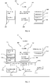
- An apparatus 100 may include a housing 110 that includes a receiving area 120 for receiving a carrier 125 comprising a fumigant and a supply system 130 adapted to extract a predetermined amount of fumigant from receiving area 120.
- Apparatus 100 may further include a controller 140 configured to control supply system 130 to extract a first portion of carrier 125 according to a treatment protocol.
- housing 110 may include any suitable material for housing fumigants, mechanical and/or electrical components. Housing 110 may be made from various polymers, painted wood or the like. In some embodiments, housing 110 may be configured to be inserted to the beehive via a bee entrance opening in the beehive. Housing 110 may have a form of a flat box (as illustrated in Figs. 3A-3B ) having at least one dimension (e.g. thickness or height) of less than the width of the beehive opening (e.g., about 18 mm).
- receiving area 120 may be an open defined area in housing 110 or may be a closed or partially closed chamber in housing 110. Receiving area 120 may include or hold carrier 125.
- carrier 125 may include absorbing material.
- the absorbing material may be soaked with fumigant. Some exemplary absorbing materials are illustrated and discussed with respect to Figs. 5 and 6 .
- automatic supply system 130 includes a delivery mechanism 135 configured to extract a first predetermined portion of carrier 125 comprising the predetermined amount of fumigant from receiving area 120.
- delivery mechanism 135 may be configured to push a trey carrying a volatile fumigant from a receiving chamber into an inner space of the beehive or a space in housing 110.
- delivery mechanism 135 may extract a portion of an absorbing material soaked with fumigant into the inner space of the beehive or a space in housing 110. The fumigant may be dried (e.g., in a solid state) on the absorbing material prior to be delivered into the beehive or at a liquid state.
- delivery mechanism 135 may be configured to retract a second predetermined portion of carrier 125 to receiving area 120. In some embodiments, by extracting and retracting carrier 125, delivery mechanism 135 may allow better control of the amount of fumigant exposed to the beehive, thus may allow a better on going control of the disinfestation process. For example, but not according to the invention, the delivery mechanism may be controlled by controller 140 to retract back into a receiving chamber at least a portion of a trey carrying liquid fumigant when a signal received by controller 140 (e.g., from a sensor such as sensor 260A illustrated in Fig. 2 ) indicates that the conditions in the beehive has changed.
- a signal received by controller 140 e.g., from a sensor such as sensor 260A illustrated in Fig. 2
- supply system 130 may include a motor (e.g., an electric motor) or any other actuator for actuating delivery mechanism 135 upon receiving a demand from controller 140.
- the motor or actuator may be configured to cause bidirectional motion of one or more motion producing elements such as: cylindrical rollers, a belt, a spring and a lead screw.
- delivery mechanism 135 may include receptacle to receive carrier 125. The receptacle may be operably connected to the one or more motion producing elements.
- controller 140 may be configured to control at least some of the electrical and/or electromechanical components of apparatus 100. Controller 140 may include at least a processor 142 and a memory 144. In some embodiments, controller 140 may further include a real-time-clock (RTC) 146. Processor 142 may be a chip or any suitable computing or computational device. Memory 144 may include a memory chip, a flash memory, a volatile memory, a non-volatile memory, a cache memory, a buffer, a short term memory unit, a long term memory unit, or other suitable memory units or storage units. Memory 144 may store any executable code, e.g., an application, a program, a process, task or script.
- RTC real-time-clock
- the executable code may include codes for controlling disinfestation of beehives according to some embodiments of the invention.
- the instructions and codes stored in memory 144 may be executed by processor 142 of controller 140.
- controller 140 may include communication unit (not illustrated) configured to communicate with external devices, such as sensors, external processors or the like.
- the communication unit may include any known wired and/or wireless communication devices.
- controller 140 may be configured to control supply system 130 to extract a first portion of carrier 115 according to a treatment protocol.
- the treatment protocol may be stored as a code in memory 144.
- controller 140 may be configured to control automatic supply system 130 to retract a second portion of carrier 125 according to the treatment protocol.
- Controller 130 may be configured to cause delivery mechanism 135 to move back and forth from receiving area 120 thus extracting and retracting carrier 125 according to the treatment protocol and/or signals received from one or more sensors 260.
- RTC 146 may allow timing of the various elements of apparatus 100 based on real time signals and processor 142 control in real-time the operation of apparatus 100.
- Apparatus 200 may include a housing 210 that includes a receiving area 220 for receiving a carrier 225, an automatic supply system 230 and a controller 240. Apparatus 200 may further include an evaporation area 250, an ignitor 260, one or more sensors 270 and a power source 280.
- housing 210 may be substantially the same as housing 110 of apparatus 100. Housing 210 may be inserted into beehive 20, for example, via the bee entrance.
- receiving area 220 may be configured to receive a carrier 225 comprising a fumigant similarly to receiving area 120 of apparatus 100.
- receiving area 220 may further include a tank 228 for holding the fumigant in a liquid phase.
- Tank 228 may be any container (either open or closed) for holding liquids.
- Tank 228 may include a pumping system for pumping the fumigant and/or a piping system for delivering the liquid fumigant to the carrier. For example, droplets of liquid fumigant may be dropped on a trey or an absorbing material (as illustrated and discussed with respect to Fig. 6B ).
- supply system 230 includes a delivery mechanism 235 configured to extract a first predetermined portion of carrier 225 that includes the predetermined amount of fumigant from receiving area 220.
- Automatic supply system 230 and delivery mechanism 235 may include substantially the same elements as supply system 130 and delivery mechanism 135 discussed above.
- controller 240 may include substantially the same elements as controller 140.
- controller 240 may be in communication with one or more sensors 270a, 270b and may receive signals from one or more sensors 270a-270b.
- Sensors 270a-270b may include sensors for sensing conditions inside beehive 20 and/or in the surroundings of beehive 20.
- Each of sensors 270a-270c may include a temperature sensor, a humidity sensor, audio sensor such as a microphone, a light sensor, a biosensor, a chemical sensor, a piezoelectric device or the like.
- Sensors 270a-270b may detect changes in the atmosphere of the beehive (e.g., temperature and humidity) and/or may detect changes in the behavior of the bees, for example, by detecting sounds and movements made by the bees.
- Controller 240 may be configured to receive signals from one or more sensors 270a-270c and analyze the signals to detect a change in the beehive. Based on the detected change (e.g., signal) controller 240 may determine or update the treatment protocol. Codes for such analysis and determination may be stored in memory 144.
- sensors 270a-270c may be located in a variety of places.
- sensor 270a may be located inside the beehive at a location different from the location of apparatus 200.
- Sensor 270a may communicate with controller 240 by wired or wireless communication.
- Sensor 270b may be located on one of the outer walls of housing 210, facing inwardly towards the internal space of the beehive and sensor 270c may be located inside housing 210.
- Sensors 270b and 270c may communicate with controller 240 by wired or wireless communication.
- apparatus 200 further includes an evaporation area 250a or 250b for evaporating the fumigant.
- delivery mechanism 235 may be configured to deliver the portion of carrier 225 comprising the fumigant to evaporation area 250a or 250b.
- Evaporation area 250a or 250b is a defined area with at least one open side to allow evaporation from evaporation area 250a or 250b to the internal space of the beehive.
- evaporation area 250a may be external to housing 210 and may include a defined area in beehive 20.
- evaporation area 250a may include the entire space of beehive 20.
- evaporation area 250b may be included in housing 210.
- evaporation area 250a or 250b may include a ventilation system (not illustrated) for actively spreading the evaporated or fumed fumigant in the beehive.
- the ventilation system may be controlled by controller 240.
- evaporation area 250a or 250b may include a heating element 265 to heat carrier 225. The heating element may actively assist in the evaporation of the fumigant from carrier 225. The heating element may be controlled by controller 240.
- evaporation area 250a or 250b may include a heating element and a ventilation system.
- apparatus 200 further includes an ignitor 260 for igniting at least carrier 225.
- Ignitor 260 may be located inside evaporation area 250a or 250b, at the exit from receiving area 220 into evaporation area 250a or 250b, at the exit from evaporation area 250a or 250b into beehive 20 or at any required place.
- Ignitor 260 may be controlled by controller 260, to ignite carrier 225 when the predetermined amount of fumigant is to be delivered into beehive 20.
- carrier 225 may include absorbing material soaked with at least the fumigant.
- An example for absorbing material may include filter paper strips, cotton fabric or any other absorbing material.
- carrier 225 may include a combustible material.
- the absorbing material may be the combustible material configured to be burned when ignited by ignitor 260.
- the absorbing material may further be soaked with a burning control material, such as sodium or potassium nitrate. The burning control material may allow a controlled burning of the carrier over a defined period of time that allows the fumigant also soaked in carrier 225 to allow full evaporation of the fumigant.
- the fumigant soaked in carrier 225 may include at least one acaricide, such as, chlorobenzilate, bromopropylate, dicofol, tedion amitraz fluvalinate or the like.
- acaricide such as, chlorobenzilate, bromopropylate, dicofol, tedion amitraz fluvalinate or the like.
- carrier 225 is a strip comprising the fumigant, for example a strip soaked with the fumigant and delivery mechanism 235 is configured to deliver a portion of the strip comprising the predetermined amount of fumigant from receiving area 210.
- carrier 225 may include a plurality of absorbing material tablets soaked with the fumigant and delivery mechanism 235 may be configured to deliver one or more tablets from receiving area 210. The tablets or strips may be delivered to evaporation area 250 or directly to beehive 20.
- carrier 225 may include volatile solid tables comprising the fumigant.
- delivery mechanism 235 may be configured to extract one or more of the volatile solid tablets from receiving area 210 to evaporation area 250a, 250b or directly to beehive 20.
- apparatus 200 may further include a power source 280, such as a battery located inside or outside housing 210.
- the battery may be a rechargeable battery.
- Power source 280 may supply power to at least some of the electrical and electromechanical elements of apparatus 200, such as supply system 230, controller 240, a ventilation system and/or heating element included in evaporation area 250, ignitor 260 and sensors 270.
- power source 280 may be or may include solar panels system for utilizing solar energy to produce electricity.
- the solar panels system may directly power at least some of the elements of apparatus 200 (or 100) or may charge a battery included in power source 280, that in return powers the at least some of the elements of apparatus 200 (or 100).
- the solar panels may be assembled on a plate attached to the beehive, or attached to any object exposed to sunlight (e.g., a pillar) being electrically connected to apparatus 200 or the beehive.
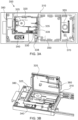
- FIGs. 3A and 3B are illustrations of top view and isometric view of an exemplary apparatus for disinfestation of beehives according to some embodiments of the invention.
- An apparatus 300 is an example of an apparatus for disinfestation of beehives by igniting and burning a portion of a carrier soaked with a fumigant.
- Apparatus 300 is given as an example for apparatuses for disinfestation of beehives only and the invention as a whole is not limited to the design of apparatus 300.
- Apparatus 300 may include housing 310, a receiving area 320 in the form of a cassette, a delivery mechanism 330 and a controller 340.
- a receiving area in a form of a cassette may include replaceable, refillable, removable case that includes at least one carrier.
- Apparatus 300 further includes evaporation chamber 350, an ignitor 360, and may further include a temperature sensor 370 and a battery 380. In the example apparatus 300 all the elements included in the apparatus are located inside housing 310.
- receiving area 320 may have a form of a replaceable cassette configured to hold a strip of combustible carrier 325.
- the replaceable cassette may be configured to be assembled and dissembled from apparatus 300. For example, every time the strip of carrier 325 has been fully consumed and should be replaced, the cassette may be either replaced with a new cassette (when the cassette is disposable) or disassembled and refilled with a new carrier (when the cassette is reusable).
- replaceable cassette receiving area 320 may be replaced by a different type of a receiving area for example, receiving area 420, illustrated and discussed with respect to Fig. 4 .. As illustrated in Fig.
- both apparatus 300 and cassette-like receiving area 320 may be opened and closed for refilling of a new carrier 325.
- Carrier 325 may include a folded strip of any combustible material, such as filter paper or cotton. Carrier 325 may be soaked with a fumigant and further may be soaked with a burning control material.
- supply system 330 includes a delivery mechanism 335 in the form of at least one (e.g. two) roller(s), an electric motor 338 and a shaft 339 configured to deliver the rotary motion from motor 338 to delivery mechanism 335.
- Delivery mechanism 335 is configured to extract (and retract if necessary) a portion of strip-like carrier 325 from cassette-like receiving area 320 to evaporation chamber 350.
- ignitor 360 is configured to ignite the portion of carrier 325 comprising a predetermined amount of fumigant in evaporation chamber 350, thus causing the fumigant soaked in the carrier to evaporate due to the heat formed by the burning of the carrier.
- chamber 350 may further include ventilation system 355 in a form of a fan that is configured to spread the evaporated fumigant from evaporation chamber 350 into the beehive.
- housing 310 may include materials (e.g., polymers/light alloys) that may endure the temperature of the burning carrier, for example, 150 °C.
- controller 340 may include any printed circuit board (PCB) that includes at least a processor and a memory (such as processor 142 and memory 144) for controlling the various controllable elements of apparatus 300.
- PCB printed circuit board
- controller 340 may control motor 338 to rotate delivery mechanism 335 to extract a portion of carrier 325 from area 320.
- Controller 340 may further be configured to cause ignitor 360 to ignite the extracted portion and cause ventilation system 355 to circulate the evaporated fumigant.
- controller 340 may be configured to receive signals indicative of the temperature in apparatus 300 and/or the beehive from sensor 370.
- controller 340 may determine when to extract the portion of the carrier and ignite the carrier based on the received signals.
- motor 338, controller 340, ventilation system 355 and sensor 370 may all be powered by battery 380.
- FIG. 4 is an illustration of an example apparatus for disinfestation of beehives according to some embodiments which do not form part of the invention.
- An apparatus 400 is an example apparatus for disinfestation of beehives by spontaneous evaporation of a volatile fumigant.
- Apparatus 400 is given as an example of apparatuses for disinfestation of beehives only and the invention as a whole is not limited to the design of apparatus 400.
- Apparatus 400 may include housing 410, a receiving area 420 in the form of a cassette, a delivery mechanism 430 and a controller 440.
- Apparatus 400 may further include evaporation chamber 450, a temperature sensor 470 and a battery 480.
- receiving area 420 may have a form of a replaceable cassette configured to hold liquid volatile fumigant and a trey-like carrier 425.
- Trey-like carrier 425 may further include an absorbing material, such as a sponge, for absorbing the liquid volatile fumigant.
- receiving area 420 may further include a tank (not illustrated) for refilling of the sponge of carrier 425 with volatile fumigant in liquid state.
- supply system 430 may include a delivery mechanism 435 in the form of two cogwheels, an electric motor 438 and a shaft 439 configured to deliver rotary motion from motor 438 to delivery mechanism 435.
- Delivery mechanism 435 may be configured to extract and retract a portion of trey-like carrier 425 and the amount of fumigant that may evaporated in evaporation chamber 450 may be determined according to the size of the portion of trey-like carrier 425 that is extracted from area 420. Accordingly, the amount of fumigant that evaporates into the beehive may be determined according to the portion of trey-like carrier 425 that was extract to the space of evaporation chamber 450.
- controller 440 may include a PCB as controller 340 of apparatus 300.
- controller 440 may cause motor 438 and delivery mechanism 435 to extract a first portion (e.g., 1 ⁇ 2 of the length) of trey-like carrier 425 to evaporation chamber 450.
- controller 440 may receive signals from sensor 470 (e.g., a thermometer), the signals may indicate that the temperature in the beehive is higher than usual. Controller 470, may then determine that the portion of carrier 425 extracted or the duration at which carrier 425 is exposed in chamber 450 should be reduced, therefore, may cause delivery mechanism 435 to retract back a second portion (e.g., 1 ⁇ 4 of the length) of trey-like carrier 425.
- apparatuses such as apparatus 300 and apparatus 400 may be configured to receive, control and use both cassette-like receiving area 320 or 420 according to a decision made by a user.
- Cassette-like receiving area 320 may include a carrier 325 in the form of folded strip made from an absorbing material. The carrier may be soaked with fumigant in either a solid or liquid state. A first portion 325a of carrier 325 may be extracted from cassette-like receiving are 320, for example, by delivery mechanism 335. The first portion may include a predetermined amount of fumigant required for the disinfestations of the beehive.
- cassette-like receiving are 320 may be configured to be openable in order to insert a new carrier 325.
- cassette-like receiving area 320 may include an upper part 321 and a lower part 322.
- the upper and lower parts are defined with respect the position of cassette-like receiving area 320 during the insertion or replacement of carrier 325.
- the two rollers that are included in delivery mechanism 335 may be split between upper part 321 and the lower part 322 respectively.
- Delivery mechanism 335 may include two cylinders, an upper rollers and a lower cylinder as will be broadly explain below with respect to Figs. 6A-6B . In the example embodiment illustrated in Figs.
- the upper cylinder is included in upper part 321 and the lower rollers is included in lower part 322, thus upon opening of cassette-like receiving are 320 the two cylinders detach from each other.
- the arrangement illustrated in Figs. 5A and 5B is an example only and any other arrangement or delivery mechanism can be included in a cassette-like receiving area 320 according to embodiments of the invention.
- a receiving area 21 may be isolated (e.g., sealed) from an evaporation area 23 which is open to the beehive (e.g., the desired fumigation space). Such embodiment may ensure that the fumigant carried by a carrier 22 may not evaporate uncontrollably into evaporation area 23.
- carrier 22 may have a form of a folded strip (e.g., made from an absorbing material) and a delivery mechanism 335 that may include one or more cylinders (e.g., rollers) 20.
- Cylinders 20 may be positioned between sealed receiving area 21 and opened evaporation area 23. Cylinders 20 may roll and extract a first predetermined portion 24 of carrier 22 into opened evaporation area 23. First portion 24 may include a predetermined amount of fumigant that may be required for fumigation of the beehive. In some embodiments, one or more cylinders 20 may roll back and retract from evaporation area 23 a second predetermined portion of carrier 22 to sealed receiving area 21.
- the fumigant may be soaked and impregnated into carrier 22 before loading carrier 22 in receiving area 21, as illustrated in Fig. 6A .
- the fumigant may be loaded or soaked into carrier 22 in receiving area 21 and/or by dripping apparatuses 25, as illustrated in Figs. 6B and 6C .
- a liquid fumigant may be controllably dripped on carrier 22 from one or more dripping apparatuses 25 located inside receiving area 21 and/or in dripping apparatuses 25.
- Dripping apparatuses 25 may include or may be connected to a liquid fumigant reservoir (e.g., a tank).
- carrier 22 may be at least partially immersed in a liquid fumigant reservoir (e.g., a tank) 26 located in sealed receiving area 21. Since carrier 22 may include strip of absorbing material, immersing at least a portion of the strip in liquid fumigant reservoir 26 may ensure (due to capillary forces) that any portion of carrier 22 is fully soaked with the liquid fumigant.
- a liquid fumigant reservoir e.g., a tank
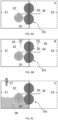
- Fig. 7A is an illustration of a delivery mechanism and an ignitor according to some embodiments of the invention.
- Delivery mechanism 355 may be substantially similar to delivery mechanism 355 disclosed above.
- an ignitor 30 may be added in order to ignite a first portion of strip-like carrier 33 when the fumigation may require to evaporate the fumigant from the carrier by heat.
- Ignitor 30 may include tightly stretched high resistant conducting wire that may be heated by conducting electric current.
- ignitor 30 may include a nickel chrome filament.
- ignitor 30 may include any other system for igniting a combustible material for example, electrodes for forming an electric arc.
- the ignitor may include an ignition system and an advancing system to allow advancing the ignition system into a contact with the combustible carrier in order to allow the ignition system to ignite the combustible carrier.
- the advancing system may retract back the ignition system.
- the ignition system may include electrodes for creating an electric arc, such as high resistant conducting wire or the like.
- the wire filament included in ignitor 30 may be stretched in an angle 31 which may be smaller than ninety degrees with respect to the surface of the strip-like carrier 33.
- carrier 33 When carrier 33 is pulled out in between cylinders 32 of delivery mechanism 335 in the direction of the wire filament, carrier 33 may physically contact point 34 on the wire filament.
- a controlled ignition of the carrier may be initiated (for example, by an instruction sent from a controller such as controller 240 to ignitor 30 to ignite the carrier).
- the wire filament of ignitor 30 may be positioned with respect to the surface of carrier 33, such that if carrier 33 is further extracted from the receiving area, after the ignition at contact point 34, at the same direction of the wire filament, carrier 33 may be capable of passing the wire filament while still contacting it, by banding at point 35, as illustrated.
- carrier 33 may continue at the same direction as long as it is continually extracted out at least by one cylinder (e.g., roller), for example,in between two cylinders 32 illustrated in Fig. 7A .
- the burning of the strip-like carrier may be passively terminated when the edge of the burning carrier reaches the at least one cylinders.
- Fig. 7B is an illustration of a delivery mechanism and an ignitor according to some embodiments of the invention.
- Delivery mechanism 335 may substantially the same as the one disclosed above.
- An ignitor 365 may include two conductive elements that when held under a predetermined voltage may cause electric discharging and the formation of electric arc 338 that may ignite carrier 33.
- a controller such as controller 140 may be configured to cause the application of the predetermined voltage during or after the predetermined portion of carrier 33 was extracted.
- Fig. 8 is a flowchart of a method of controlling disinfestation of beehives according to some embodiments of the invention.
- the method of Fig. 8 is performed by a controller, such as controller 140 of apparatus 100 or 240 of apparatus 200.
- Box 810 includes determining a treatment protocol for supplying a fumigant to a beehive, the treatment protocol including supplying a predetermined amount of fumigant at a predetermined time.
- determining the treatment protocol may include receiving the treatment protocol from a beekeeper or any other user.
- a beekeeper may pre-program controller 140 or 240 to supply to the beehive the predetermined amount of fumigant at the predetermined time.
- determining the treatment protocol may include receiving one or more signals indicative of conditions inside the beehive, for example, signals indicative of the temperature, humidity, the activity level of the bees etc.
- the signals may be received from a sensor such as sensor 270A-270C.
- determining the treatment protocol may be based on the received one or more signals. For example, the timing of application of the predetermined amount of fumigant may be determined based on the activity level of the bees in the beehive and/or the predetermined amount of fumigant may be determined based on the temperature in the beehive.
- Box 820 includes controlling an automatic supply system (e.g., system 130 or 230) to extract a first predetermined portion of a carrier (e.g., carrier 125 or 225) comprising the predetermined amount of fumigant from a receiving area (e.g., receiving area 120 or 220) according to the treatment protocol.
- the automatic supply system includes a delivery mechanism (e.g., delivery mechanism 135, 235 or 335) configured to extract the first predetermined portion of the carrier, from the receiving area.
- controlling the automatic supply system may include retracting a second predetermined portion of the carrier to the receiving area.
Claims (14)
- Appareil de désinfestation de ruches, comprenant :
un boîtier (110) comprenant :une zone de réception (120, 220, 320) pour recevoir une bande (125, 225, 325) comprenant un fumigant ;un système d'alimentation automatique (130, 230, 330) adapté pour extraire une partie prédéterminée de la bande de la zone de réception à une zone d'évaporation (250, 250a, 250b, 23), où la zone d'évaporation est définie avec au moins un côté ouvert pour permettre l'évaporation du fumigant de la zone d'évaporation à un espace interne de la ruche ; etun allumeur (260, 360), situé au niveau de la zone d'évaporation, pour allumer et brûler la partie prédéterminée de la bande,dans lequel le système d'alimentation automatique comprend :un mécanisme de distribution (135, 235, 335) qui est configuré pour extraire la partie prédéterminée de la bande de la zone de réception ; etun dispositif de commande (140, 240, 340) configuré pour commander le système d'alimentation automatique pour extraire la partie de la bande selon un protocole de traitement. - Appareil de la revendication 1, dans lequel la bande est l'un : d'un papier filtre et d'un tissu de coton.
- Appareil de la revendication 1, dans lequel la bande comprend un matériau absorbant.
- Appareil selon l'une quelconque des revendications précédentes, dans lequel la bande comprend au moins l'un : d'un matériau combustible et d'un matériau de contrôle de brûlage.
- Appareil selon l'une quelconque des revendications précédentes, dans lequel la zone d'évaporation comprend au moins l'un : d'un système de ventilation (355) et d'un élément chauffant (265) pour chauffer la bande.
- Appareil selon l'une quelconque des revendications précédentes, dans lequel l'allumeur provoque une décharge électrique et, la formation d'arc électrique (338).
- Appareil selon l'une quelconque des revendications précédentes, comprenant des moyens pour terminer le brûlage de la bande.
- Appareil selon l'une quelconque des revendications précédentes, dans lequel le boîtier est configuré pour être inséré dans la ruche via une ouverture d'entrée d'abeilles dans la ruche.
- Appareil selon l'une quelconque des revendications précédentes, dans lequel le mécanisme de distribution comprend au moins l'un : d'un ou de plusieurs rouleau(x) cylindrique(s), d'une courroie, d'un ressort, d'une vis mère et d'un réceptacle pour recevoir la bande.
- Appareil selon l'une quelconque des revendications précédentes, dans lequel le système d'alimentation automatique comprend en outre un moteur pour faire fonctionner le mécanisme de distribution.
- Appareil selon l'une quelconque des revendications précédentes, dans lequel la zone d'évaporation est incluse dans le boîtier.
- Appareil selon l'une quelconque des revendications précédentes, comprenant en outre au moins un capteur configuré pour détecter les conditions à l'intérieur de la ruche, et dans lequel le dispositif de commande est en outre configuré pour commander le système d'alimentation automatique sur la base de signaux reçus de l' au moins un capteur.
- Procédé de commande de désinfestation de ruches, comprenant les étapes consistant à :
déterminer un protocole de traitement pour fournir un fumigant à une ruche, le protocole de traitement comprend les étapes consistant à :fournir une quantité prédéterminée de fumigant à un moment prédéterminé en utilisant un appareil selon l'une quelconque des revendications précédentes ; etcommander le système d'alimentation automatique dudit appareil pour extraire une partie prédéterminée d'une bande comprenant le fumigant de la zone de réception dudit appareil selon le protocole de traitement ; etallumer et brûler la partie prédéterminée extraite de la bande, par l'allumeur situé au niveau de la zone d'évaporation dudit appareil. - Procédé de la revendication 13, comprenant en outre les étapes consistant à :recevoir, d'un ou de plusieurs capteur(s), un signal ou plusieurs signaux indiquant les conditions à l'intérieur de la ruche ; etdéterminer le protocole de traitement sur la base du signal ou des plusieurs signaux reçu(s).
Applications Claiming Priority (2)
| Application Number | Priority Date | Filing Date | Title |
|---|---|---|---|
| US201562175349P | 2015-06-14 | 2015-06-14 | |
| PCT/IL2016/050598 WO2016203463A1 (fr) | 2015-06-14 | 2016-06-08 | Appareil de désinfestation de ruches et son procédé de commande |
Publications (3)
| Publication Number | Publication Date |
|---|---|
| EP3307060A1 EP3307060A1 (fr) | 2018-04-18 |
| EP3307060A4 EP3307060A4 (fr) | 2019-02-27 |
| EP3307060B1 true EP3307060B1 (fr) | 2023-03-08 |
Family
ID=57545311
Family Applications (1)
| Application Number | Title | Priority Date | Filing Date |
|---|---|---|---|
| EP16811131.8A Active EP3307060B1 (fr) | 2015-06-14 | 2016-06-08 | Appareil de désinfestation de ruches et son procédé de commande |
Country Status (9)
| Country | Link |
|---|---|
| US (1) | US10986819B2 (fr) |
| EP (1) | EP3307060B1 (fr) |
| KR (1) | KR102655574B1 (fr) |
| CN (1) | CN107846870B (fr) |
| ES (1) | ES2949155T3 (fr) |
| IL (1) | IL256152B (fr) |
| PL (1) | PL3307060T3 (fr) |
| RU (1) | RU2727652C2 (fr) |
| WO (1) | WO2016203463A1 (fr) |
Families Citing this family (11)
| Publication number | Priority date | Publication date | Assignee | Title |
|---|---|---|---|---|
| EP3547829A4 (fr) * | 2016-12-02 | 2020-07-08 | Bee Vectoring Technology Inc. | Systèmes d'inoculation pour ruches d'abeilles et procédés associés |
| WO2018165051A1 (fr) * | 2017-03-06 | 2018-09-13 | Butzloff Peter Robert | Appareil, procédés et médicaments pour le traitement d'insectes pollinisateurs |
| US11957113B2 (en) * | 2017-11-13 | 2024-04-16 | Beewise Technologies Ltd | Automatic beehives |
| JP2021506766A (ja) * | 2017-12-14 | 2021-02-22 | バックヨル リミテッド | 異方的なナノ粒子組成物及び方法 |
| CN109308791A (zh) * | 2018-11-23 | 2019-02-05 | 成都工业学院 | 一种熏匹器控制方法及智能熏匹器 |
| FR3096229A1 (fr) * | 2019-05-21 | 2020-11-27 | Institut National De La Recherche Agronomique - Inra | Ruche connectee permettant le suivi a distance de l’etat de sante d’une colonie d’abeilles |
| US11146211B1 (en) | 2019-06-25 | 2021-10-12 | John B. Jacob | Photovoltaic horizontal beehive system |
| CN111066689B (zh) * | 2019-12-11 | 2021-04-16 | 浙江大学 | 一种利用寄生蜂防控巢虫的装置及其应用 |
| IT202000021880A1 (it) * | 2020-09-17 | 2020-12-17 | Nicola Pietropoli | Dosatore elettronico per acido Formico allo stato liquido per il controllo della Varroa destructor, parassita delle api. |
| CN113455424A (zh) * | 2021-08-17 | 2021-10-01 | 宁夏晓鸣农牧股份有限公司 | 一种甲醛气体熏蒸种蛋的装置及方法 |
| US11895989B2 (en) | 2022-07-04 | 2024-02-13 | Beewise Technologies Ltd | Automated beehive control and management |
Citations (2)
| Publication number | Priority date | Publication date | Assignee | Title |
|---|---|---|---|---|
| EP0239802A2 (fr) * | 1986-03-04 | 1987-10-07 | Daiken Iko Kabushiki Kaisha | Procédé et appareil pour évaporer une substance active |
| US20140127968A1 (en) * | 2011-06-06 | 2014-05-08 | Gene Probasco | Methods and compositions for controlling a honey bee parasitic mite infestation |
Family Cites Families (49)
| Publication number | Priority date | Publication date | Assignee | Title |
|---|---|---|---|---|
| US2624925A (en) * | 1953-01-13 | Si-leetsxsi leet l | ||
| DE486530C (de) * | 1929-03-02 | 1929-11-18 | Brabender Elmasch G M B H | Verfahren zur kontinuierlichen Erzeugung von nikotinhaltigen Gasen aus impraegniertem Papier |
| US3754861A (en) * | 1971-08-09 | 1973-08-28 | Daito Match Kogyo K K | Formed solid fumigant with an ignition head |
| US3778924A (en) * | 1972-07-21 | 1973-12-18 | Kodama Brothers Co Ltd | Insecticidal fumigator |
| US4286754A (en) * | 1976-05-10 | 1981-09-01 | Minnesota Mining And Manufacturing Company | Controlled-rate liquid dispenser |
| SU891037A1 (ru) * | 1979-03-23 | 1981-12-23 | за витель И. Я. Шекшуев | Роевн И.Я.Шекшуева |
| GB2122903B (en) * | 1982-06-22 | 1986-11-05 | Masayuki Takamori | Vaporizers for vaporisable substances and support media for substances usable therewith |
| DE3308017C1 (de) * | 1983-03-07 | 1984-03-29 | Richard 6148 Heppenheim Fischer | Verfahren und Vorrichtung zur Bekämpfung des Milben-Befalls von Bienenvölkern |
| IT8322054V0 (it) * | 1983-06-07 | 1983-06-07 | Insao Spa | Dispositivo per il riscaldamento di piastrine impregnate di sostanze evaporabili. |
| DE3335808A1 (de) * | 1983-10-01 | 1985-08-01 | Heinrich 7298 Loßburg Seeger | Verfahren und vorrichtung zur bekaempfung von bienenschaedlingen |
| EP0218162A3 (fr) | 1985-10-07 | 1987-08-12 | Friedrich Finkbeiner | Vaporiseur à acide formique pour la lutte contre la varroatose |
| DE3538688A1 (de) | 1985-10-31 | 1987-05-07 | Bayer Ag | Verfahren zur bekaempfung von parasitosen bei bienen |
| JPS6480242A (en) * | 1987-09-24 | 1989-03-27 | Oshita Sangyo Kk | Insecticidal tape cassette |
| WO1990012644A1 (fr) * | 1989-04-21 | 1990-11-01 | S.C. Johnson & Son, Inc. | Appareil d'allumage de materiaux combustibles enfermes |
| WO1990013327A1 (fr) * | 1989-04-28 | 1990-11-15 | Riker Laboratories, Inc. | Dispositif d'inhalation de poudre seche |
| GB8909891D0 (en) * | 1989-04-28 | 1989-06-14 | Riker Laboratories Inc | Device |
| FR2660157A1 (fr) * | 1990-03-27 | 1991-10-04 | Percic Stanislas | Boitier diffuseur d'insecticide pour ruches. |
| CN2072332U (zh) * | 1990-06-26 | 1991-03-06 | 中国农科院蜜蜂所 | 新型杀螨药片 |
| US5479948A (en) * | 1993-08-10 | 1996-01-02 | Philip Morris Incorporated | Electrical smoking article having continuous tobacco flavor web and flavor cassette therefor |
| CN1069619A (zh) * | 1991-08-22 | 1993-03-10 | 陈信洁 | 防蜂螨防幼虫腐臭病蜜蜂巢础 |
| US5657574A (en) * | 1996-05-13 | 1997-08-19 | S. C. Johnson & Son, Inc. | Coiled insect fumigant |
| DE19636498A1 (de) * | 1996-09-09 | 1998-03-12 | Wilhelm Buschack | Applikator-Verdunstungsgerät Einrichtung zum Verdunsten von Flüssigkeiten, Säuren, Alkohol u. a., für die Behandlung von Bienenvölkern |
| US6078728A (en) * | 1998-06-22 | 2000-06-20 | S. C. Johnson & Son, Inc. | Volatile carrier for use with a heating device |
| DE19943711A1 (de) * | 1999-09-08 | 2001-03-15 | Bruno Becker | Vorrichtung zum kontinuierlichen Verdunsten von Flüssigkeiten, insbesondere Ameisensäure |
| US6446426B1 (en) * | 2000-05-03 | 2002-09-10 | Philip Morris Incorporated | Miniature pulsed heat source |
| RU2239313C2 (ru) | 2001-01-03 | 2004-11-10 | Огурцов Александр Федорович | Электрическая тиндализационная камера огурцова для дезинфекции пчелиных сотов |
| US6620025B2 (en) * | 2001-04-12 | 2003-09-16 | Theodore W. Scheuneman | Evaporator for the treatment of honey bee diseases and undesirable hive conditions |
| ITMI20012121A1 (it) * | 2001-10-15 | 2003-04-15 | Zobele Ind Chim | Dispossitivo riscaldante per elettroemanatore |
| DE10309323A1 (de) * | 2003-03-04 | 2004-09-16 | Wilhelm Buschack | Verdunstungs-Applikator zur Bekämpfung von Bienenkrankheiten |
| US6871794B2 (en) * | 2003-05-01 | 2005-03-29 | E. I. Du Pont De Nemours And Company | Liquid dispersion device |
| FR2894431B1 (fr) * | 2005-12-12 | 2012-12-07 | Michel Christian Martinez | Procede de lutte contre l'infestation des ruches par des acariens et ruche amenagee a cet effet. |
| DE102006021144B3 (de) * | 2006-05-06 | 2007-09-27 | Wilfried Kalinka | Bienenbeute und Verdunster zur Bekämpfung von Krankheiten und Schädlingen bei Bienenvölkern |
| KR20080014946A (ko) * | 2006-08-12 | 2008-02-15 | 이봉균 | 해충구제용 개미산 구제제 분산 기화기 |
| KR100967996B1 (ko) * | 2008-02-15 | 2010-07-07 | 사천시농업기술센터 | 꿀벌 응애 구제기 |
| GB0822000D0 (en) * | 2008-12-02 | 2009-01-07 | Vita Europ Ltd | Control of parasites |
| DE202009002120U1 (de) | 2009-02-13 | 2009-04-23 | Hörmann, Jan | Verdunstungsvorrichtung zur Bekämpfung von Schädlingen |
| JP2010268697A (ja) * | 2009-05-19 | 2010-12-02 | Sharp Corp | 殺虫装置 |
| CA2736999C (fr) * | 2010-04-01 | 2015-02-17 | Murray Pask | Methode et appareil de lutte contre les animaux nuisibles fouisseurs |
| KR101218110B1 (ko) * | 2010-06-24 | 2013-01-03 | 배재환 | 양봉용 구제약품 기화 장치 |
| US9357759B2 (en) * | 2010-08-20 | 2016-06-07 | Deere & Company | Networked chemical dispersion system |
| CN102308762B (zh) * | 2011-07-15 | 2013-01-09 | 葛凤晨 | 微型蜂巢原生态蜜及生产方法和设备 |
| WO2014151732A1 (fr) | 2013-03-15 | 2014-09-25 | Basf Se | Système de mélange et de distribution de pesticide automatisé et procédé d'utilisation |
| DE102013006265A1 (de) | 2013-04-11 | 2014-10-16 | Richard Rossa | Vorrichtung und Verfahren zur Bekämpfung von Varroa-Milben im Bienenstock |
| CN103238631B (zh) * | 2013-05-23 | 2014-06-04 | 中国农业科学院蜜蜂研究所 | 杀灭巢虫及其卵的环保杀虫剂 |
| DE102013214609A1 (de) | 2013-07-26 | 2015-01-29 | Varta Microbattery Gmbh | Verfahren und Vorrichtung zur Bekämpfung von Bienenschädlingen |
| CN103858887A (zh) * | 2014-03-12 | 2014-06-18 | 许立军 | 一种防治巢虫的药物及其制备方法 |
| DE102014110009B4 (de) * | 2014-07-16 | 2018-02-22 | Gerhard Bader | Verdunstungsvorrichtung und Verfahren zum Verdunsten einer Flüssigkeit |
| DE102016001934B4 (de) * | 2016-02-18 | 2024-02-01 | Christian Petersen | Verdunster |
| DE202017100888U1 (de) * | 2017-02-17 | 2017-03-02 | Joachim Weiland Werkzeugbau GmbH & Co. KG | Verdunstersysteme, umfassend eine Verdunstereinheit für Ameisensäure und ein an die Verdunstereinheit angepasstes Standard-Wabenleerrähmchen |
-
2016
- 2016-06-08 US US15/580,283 patent/US10986819B2/en active Active
- 2016-06-08 CN CN201680034543.2A patent/CN107846870B/zh active Active
- 2016-06-08 PL PL16811131.8T patent/PL3307060T3/pl unknown
- 2016-06-08 ES ES16811131T patent/ES2949155T3/es active Active
- 2016-06-08 RU RU2017147038A patent/RU2727652C2/ru active
- 2016-06-08 EP EP16811131.8A patent/EP3307060B1/fr active Active
- 2016-06-08 WO PCT/IL2016/050598 patent/WO2016203463A1/fr active Application Filing
- 2016-06-08 KR KR1020187001128A patent/KR102655574B1/ko active IP Right Grant
-
2017
- 2017-12-06 IL IL256152A patent/IL256152B/en unknown
Patent Citations (2)
| Publication number | Priority date | Publication date | Assignee | Title |
|---|---|---|---|---|
| EP0239802A2 (fr) * | 1986-03-04 | 1987-10-07 | Daiken Iko Kabushiki Kaisha | Procédé et appareil pour évaporer une substance active |
| US20140127968A1 (en) * | 2011-06-06 | 2014-05-08 | Gene Probasco | Methods and compositions for controlling a honey bee parasitic mite infestation |
Also Published As
| Publication number | Publication date |
|---|---|
| EP3307060A4 (fr) | 2019-02-27 |
| PL3307060T4 (pl) | 2023-07-24 |
| CN107846870B (zh) | 2021-04-20 |
| IL256152B (en) | 2022-05-01 |
| ES2949155T3 (es) | 2023-09-26 |
| WO2016203463A1 (fr) | 2016-12-22 |
| EP3307060A1 (fr) | 2018-04-18 |
| KR20180021380A (ko) | 2018-03-02 |
| US20180160656A1 (en) | 2018-06-14 |
| KR102655574B1 (ko) | 2024-04-05 |
| IL256152A (en) | 2018-02-28 |
| RU2727652C2 (ru) | 2020-07-22 |
| CN107846870A (zh) | 2018-03-27 |
| RU2017147038A3 (fr) | 2019-12-25 |
| US10986819B2 (en) | 2021-04-27 |
| PL3307060T3 (pl) | 2023-07-24 |
| NZ738358A (en) | 2023-04-28 |
| RU2017147038A (ru) | 2019-07-15 |
Similar Documents
| Publication | Publication Date | Title |
|---|---|---|
| EP3307060B1 (fr) | Appareil de désinfestation de ruches et son procédé de commande | |
| US6909840B2 (en) | Localized surface volatilization | |
| PT101738B (pt) | Vaporizador de insecticida accionado por pilha electrica e processo para a vaporizacao de um insecticida | |
| CN113543666B (zh) | 气溶胶生成装置及其控制方法和计算机可读记录介质 | |
| CA3006602A1 (fr) | Dispositif generateur d'aerosol comportant un compartiment etanche | |
| US20070257016A1 (en) | Heated Device for Dispensing a Volatile Active | |
| US3778924A (en) | Insecticidal fumigator | |
| EP0911041A2 (fr) | Dispositif de vaporisation électrique de substances actives | |
| BR112019011331A2 (pt) | sistemas de inoculação para colmeias de abelha e métodos relacionados | |
| JP2022130582A (ja) | エアロゾル生成装置及びその動作方法 | |
| NZ738358B2 (en) | Apparatus for disinfestation of beehives and method for controlling same | |
| KR102587109B1 (ko) | 에어로졸 생성 장치 | |
| KR101156166B1 (ko) | 꿀벌 병해충 방제용 훈증기 | |
| JP2010510830A5 (fr) | ||
| KR102663245B1 (ko) | 에어로졸 생성 장치 | |
| CA2295898C (fr) | Evaporateur pour le traitement de maladies associees a l'abeille domestique et de conditions de ruches desagreables | |
| JPS598546Y2 (ja) | 蚊取器 | |
| CN116261405A (zh) | 用于对供给至加热器的电力进行控制的气溶胶生成装置及其操作方法 | |
| JP2004065261A (ja) | 間欠式薬剤揮散装置及びこれを用いた害虫防除方法 | |
| JPS605814Y2 (ja) | 殺虫装置 | |
| JP5813410B2 (ja) | 液体の蒸発を促進する方法、蒸発促進装置およびそれを備えた電気機器 | |
| JP2000023612A (ja) | 電池式殺虫剤蒸散装置および殺虫剤蒸散方法 | |
| EA040428B1 (ru) | Узел нагрева для устройства, генерирующего пар | |
| CZ24881U1 (cs) | Řízený odpařovač kapalin, zvláště vhodný pro včelaření | |
| KR19990049956A (ko) | 피. 씨. 티를 이용한 유황 훈증기 |
Legal Events
| Date | Code | Title | Description |
|---|---|---|---|
| STAA | Information on the status of an ep patent application or granted ep patent |
Free format text: STATUS: THE INTERNATIONAL PUBLICATION HAS BEEN MADE |
|
| PUAI | Public reference made under article 153(3) epc to a published international application that has entered the european phase |
Free format text: ORIGINAL CODE: 0009012 |
|
| STAA | Information on the status of an ep patent application or granted ep patent |
Free format text: STATUS: REQUEST FOR EXAMINATION WAS MADE |
|
| 17P | Request for examination filed |
Effective date: 20171206 |
|
| AK | Designated contracting states |
Kind code of ref document: A1 Designated state(s): AL AT BE BG CH CY CZ DE DK EE ES FI FR GB GR HR HU IE IS IT LI LT LU LV MC MK MT NL NO PL PT RO RS SE SI SK SM TR |
|
| AX | Request for extension of the european patent |
Extension state: BA ME |
|
| DAV | Request for validation of the european patent (deleted) | ||
| DAX | Request for extension of the european patent (deleted) | ||
| A4 | Supplementary search report drawn up and despatched |
Effective date: 20190124 |
|
| RIC1 | Information provided on ipc code assigned before grant |
Ipc: A01M 13/00 20060101ALI20190118BHEP Ipc: A01K 51/00 20060101AFI20190118BHEP |
|
| RAP1 | Party data changed (applicant data changed or rights of an application transferred) |
Owner name: TOBE INFLUENCE INNOVATION LTD. |
|
| RIN1 | Information on inventor provided before grant (corrected) |
Inventor name: YOGEV, OFFER Inventor name: BEN-SHIMON, AVRAHAM |
|
| RIN1 | Information on inventor provided before grant (corrected) |
Inventor name: YOGEV, OFFER Inventor name: BEN-SHIMON, AVRAHAM |
|
| STAA | Information on the status of an ep patent application or granted ep patent |
Free format text: STATUS: EXAMINATION IS IN PROGRESS |
|
| 17Q | First examination report despatched |
Effective date: 20210507 |
|
| STAA | Information on the status of an ep patent application or granted ep patent |
Free format text: STATUS: EXAMINATION IS IN PROGRESS |
|
| GRAP | Despatch of communication of intention to grant a patent |
Free format text: ORIGINAL CODE: EPIDOSNIGR1 |
|
| STAA | Information on the status of an ep patent application or granted ep patent |
Free format text: STATUS: GRANT OF PATENT IS INTENDED |
|
| INTG | Intention to grant announced |
Effective date: 20220916 |
|
| GRAS | Grant fee paid |
Free format text: ORIGINAL CODE: EPIDOSNIGR3 |
|
| GRAA | (expected) grant |
Free format text: ORIGINAL CODE: 0009210 |
|
| STAA | Information on the status of an ep patent application or granted ep patent |
Free format text: STATUS: THE PATENT HAS BEEN GRANTED |
|
| AK | Designated contracting states |
Kind code of ref document: B1 Designated state(s): AL AT BE BG CH CY CZ DE DK EE ES FI FR GB GR HR HU IE IS IT LI LT LU LV MC MK MT NL NO PL PT RO RS SE SI SK SM TR |
|
| REG | Reference to a national code |
Ref country code: GB Ref legal event code: FG4D |
|
| REG | Reference to a national code |
Ref country code: CH Ref legal event code: EP Ref country code: AT Ref legal event code: REF Ref document number: 1551951 Country of ref document: AT Kind code of ref document: T Effective date: 20230315 |
|
| REG | Reference to a national code |
Ref country code: DE Ref legal event code: R096 Ref document number: 602016078213 Country of ref document: DE |
|
| REG | Reference to a national code |
Ref country code: IE Ref legal event code: FG4D |
|
| REG | Reference to a national code |
Ref country code: LT Ref legal event code: MG9D |
|
| P01 | Opt-out of the competence of the unified patent court (upc) registered |
Effective date: 20230601 |
|
| REG | Reference to a national code |
Ref country code: NL Ref legal event code: MP Effective date: 20230308 |
|
| PG25 | Lapsed in a contracting state [announced via postgrant information from national office to epo] |
Ref country code: RS Free format text: LAPSE BECAUSE OF FAILURE TO SUBMIT A TRANSLATION OF THE DESCRIPTION OR TO PAY THE FEE WITHIN THE PRESCRIBED TIME-LIMIT Effective date: 20230308 Ref country code: NO Free format text: LAPSE BECAUSE OF FAILURE TO SUBMIT A TRANSLATION OF THE DESCRIPTION OR TO PAY THE FEE WITHIN THE PRESCRIBED TIME-LIMIT Effective date: 20230608 Ref country code: LV Free format text: LAPSE BECAUSE OF FAILURE TO SUBMIT A TRANSLATION OF THE DESCRIPTION OR TO PAY THE FEE WITHIN THE PRESCRIBED TIME-LIMIT Effective date: 20230308 Ref country code: LT Free format text: LAPSE BECAUSE OF FAILURE TO SUBMIT A TRANSLATION OF THE DESCRIPTION OR TO PAY THE FEE WITHIN THE PRESCRIBED TIME-LIMIT Effective date: 20230308 Ref country code: HR Free format text: LAPSE BECAUSE OF FAILURE TO SUBMIT A TRANSLATION OF THE DESCRIPTION OR TO PAY THE FEE WITHIN THE PRESCRIBED TIME-LIMIT Effective date: 20230308 |
|
| PGFP | Annual fee paid to national office [announced via postgrant information from national office to epo] |
Ref country code: RO Payment date: 20230608 Year of fee payment: 8 Ref country code: DE Payment date: 20230613 Year of fee payment: 8 |
|
| REG | Reference to a national code |
Ref country code: AT Ref legal event code: MK05 Ref document number: 1551951 Country of ref document: AT Kind code of ref document: T Effective date: 20230308 |
|
| PG25 | Lapsed in a contracting state [announced via postgrant information from national office to epo] |
Ref country code: SE Free format text: LAPSE BECAUSE OF FAILURE TO SUBMIT A TRANSLATION OF THE DESCRIPTION OR TO PAY THE FEE WITHIN THE PRESCRIBED TIME-LIMIT Effective date: 20230308 Ref country code: NL Free format text: LAPSE BECAUSE OF FAILURE TO SUBMIT A TRANSLATION OF THE DESCRIPTION OR TO PAY THE FEE WITHIN THE PRESCRIBED TIME-LIMIT Effective date: 20230308 Ref country code: GR Free format text: LAPSE BECAUSE OF FAILURE TO SUBMIT A TRANSLATION OF THE DESCRIPTION OR TO PAY THE FEE WITHIN THE PRESCRIBED TIME-LIMIT Effective date: 20230609 Ref country code: FI Free format text: LAPSE BECAUSE OF FAILURE TO SUBMIT A TRANSLATION OF THE DESCRIPTION OR TO PAY THE FEE WITHIN THE PRESCRIBED TIME-LIMIT Effective date: 20230308 |
|
| PGFP | Annual fee paid to national office [announced via postgrant information from national office to epo] |
Ref country code: PL Payment date: 20230608 Year of fee payment: 8 |
|
| REG | Reference to a national code |
Ref country code: ES Ref legal event code: FG2A Ref document number: 2949155 Country of ref document: ES Kind code of ref document: T3 Effective date: 20230926 |
|
| PG25 | Lapsed in a contracting state [announced via postgrant information from national office to epo] |
Ref country code: SM Free format text: LAPSE BECAUSE OF FAILURE TO SUBMIT A TRANSLATION OF THE DESCRIPTION OR TO PAY THE FEE WITHIN THE PRESCRIBED TIME-LIMIT Effective date: 20230308 Ref country code: PT Free format text: LAPSE BECAUSE OF FAILURE TO SUBMIT A TRANSLATION OF THE DESCRIPTION OR TO PAY THE FEE WITHIN THE PRESCRIBED TIME-LIMIT Effective date: 20230710 Ref country code: EE Free format text: LAPSE BECAUSE OF FAILURE TO SUBMIT A TRANSLATION OF THE DESCRIPTION OR TO PAY THE FEE WITHIN THE PRESCRIBED TIME-LIMIT Effective date: 20230308 Ref country code: CZ Free format text: LAPSE BECAUSE OF FAILURE TO SUBMIT A TRANSLATION OF THE DESCRIPTION OR TO PAY THE FEE WITHIN THE PRESCRIBED TIME-LIMIT Effective date: 20230308 Ref country code: AT Free format text: LAPSE BECAUSE OF FAILURE TO SUBMIT A TRANSLATION OF THE DESCRIPTION OR TO PAY THE FEE WITHIN THE PRESCRIBED TIME-LIMIT Effective date: 20230308 |
|
| PGFP | Annual fee paid to national office [announced via postgrant information from national office to epo] |
Ref country code: IT Payment date: 20230721 Year of fee payment: 8 Ref country code: ES Payment date: 20230704 Year of fee payment: 8 |
|
| PG25 | Lapsed in a contracting state [announced via postgrant information from national office to epo] |
Ref country code: SK Free format text: LAPSE BECAUSE OF FAILURE TO SUBMIT A TRANSLATION OF THE DESCRIPTION OR TO PAY THE FEE WITHIN THE PRESCRIBED TIME-LIMIT Effective date: 20230308 Ref country code: IS Free format text: LAPSE BECAUSE OF FAILURE TO SUBMIT A TRANSLATION OF THE DESCRIPTION OR TO PAY THE FEE WITHIN THE PRESCRIBED TIME-LIMIT Effective date: 20230708 |
|
| REG | Reference to a national code |
Ref country code: DE Ref legal event code: R097 Ref document number: 602016078213 Country of ref document: DE |
|
| PLBE | No opposition filed within time limit |
Free format text: ORIGINAL CODE: 0009261 |
|
| STAA | Information on the status of an ep patent application or granted ep patent |
Free format text: STATUS: NO OPPOSITION FILED WITHIN TIME LIMIT |
|
| PG25 | Lapsed in a contracting state [announced via postgrant information from national office to epo] |
Ref country code: MC Free format text: LAPSE BECAUSE OF FAILURE TO SUBMIT A TRANSLATION OF THE DESCRIPTION OR TO PAY THE FEE WITHIN THE PRESCRIBED TIME-LIMIT Effective date: 20230308 |
|
| PG25 | Lapsed in a contracting state [announced via postgrant information from national office to epo] |
Ref country code: SI Free format text: LAPSE BECAUSE OF FAILURE TO SUBMIT A TRANSLATION OF THE DESCRIPTION OR TO PAY THE FEE WITHIN THE PRESCRIBED TIME-LIMIT Effective date: 20230308 Ref country code: MC Free format text: LAPSE BECAUSE OF FAILURE TO SUBMIT A TRANSLATION OF THE DESCRIPTION OR TO PAY THE FEE WITHIN THE PRESCRIBED TIME-LIMIT Effective date: 20230308 Ref country code: DK Free format text: LAPSE BECAUSE OF FAILURE TO SUBMIT A TRANSLATION OF THE DESCRIPTION OR TO PAY THE FEE WITHIN THE PRESCRIBED TIME-LIMIT Effective date: 20230308 |
|
| REG | Reference to a national code |
Ref country code: CH Ref legal event code: PL |
|
| 26N | No opposition filed |
Effective date: 20231211 |
|
| REG | Reference to a national code |
Ref country code: BE Ref legal event code: MM Effective date: 20230630 |
|
| GBPC | Gb: european patent ceased through non-payment of renewal fee |
Effective date: 20230608 |
|
| PG25 | Lapsed in a contracting state [announced via postgrant information from national office to epo] |
Ref country code: LU Free format text: LAPSE BECAUSE OF NON-PAYMENT OF DUE FEES Effective date: 20230608 |
|
| REG | Reference to a national code |
Ref country code: IE Ref legal event code: MM4A |
|
| PG25 | Lapsed in a contracting state [announced via postgrant information from national office to epo] |
Ref country code: LU Free format text: LAPSE BECAUSE OF NON-PAYMENT OF DUE FEES Effective date: 20230608 |
|
| PG25 | Lapsed in a contracting state [announced via postgrant information from national office to epo] |
Ref country code: IE Free format text: LAPSE BECAUSE OF NON-PAYMENT OF DUE FEES Effective date: 20230608 |
|
| PG25 | Lapsed in a contracting state [announced via postgrant information from national office to epo] |
Ref country code: IE Free format text: LAPSE BECAUSE OF NON-PAYMENT OF DUE FEES Effective date: 20230608 Ref country code: GB Free format text: LAPSE BECAUSE OF NON-PAYMENT OF DUE FEES Effective date: 20230608 Ref country code: CH Free format text: LAPSE BECAUSE OF NON-PAYMENT OF DUE FEES Effective date: 20230630 |