EP3306702B1 - Sekundärbatteriepack - Google Patents
Sekundärbatteriepack Download PDFInfo
- Publication number
- EP3306702B1 EP3306702B1 EP16875910.8A EP16875910A EP3306702B1 EP 3306702 B1 EP3306702 B1 EP 3306702B1 EP 16875910 A EP16875910 A EP 16875910A EP 3306702 B1 EP3306702 B1 EP 3306702B1
- Authority
- EP
- European Patent Office
- Prior art keywords
- terminal cover
- terminal
- secondary battery
- battery pack
- stopper
- Prior art date
- Legal status (The legal status is an assumption and is not a legal conclusion. Google has not performed a legal analysis and makes no representation as to the accuracy of the status listed.)
- Active
Links
- 238000010168 coupling process Methods 0.000 claims description 17
- 238000005859 coupling reaction Methods 0.000 claims description 17
- 230000008878 coupling Effects 0.000 claims description 16
- 230000000994 depressogenic effect Effects 0.000 claims description 6
- 230000000881 depressing effect Effects 0.000 claims description 3
- 238000007599 discharging Methods 0.000 description 7
- 238000000034 method Methods 0.000 description 4
- 238000010586 diagram Methods 0.000 description 3
- 239000004020 conductor Substances 0.000 description 2
- 238000003780 insertion Methods 0.000 description 2
- 230000037431 insertion Effects 0.000 description 2
- 239000000463 material Substances 0.000 description 2
- OKTJSMMVPCPJKN-UHFFFAOYSA-N Carbon Chemical compound [C] OKTJSMMVPCPJKN-UHFFFAOYSA-N 0.000 description 1
- 230000002159 abnormal effect Effects 0.000 description 1
- 230000004308 accommodation Effects 0.000 description 1
- 229910052799 carbon Inorganic materials 0.000 description 1
- 230000015556 catabolic process Effects 0.000 description 1
- 230000001419 dependent effect Effects 0.000 description 1
- 230000000694 effects Effects 0.000 description 1
- 230000005489 elastic deformation Effects 0.000 description 1
- 238000005516 engineering process Methods 0.000 description 1
- 239000012535 impurity Substances 0.000 description 1
- 238000012423 maintenance Methods 0.000 description 1
- 239000002184 metal Substances 0.000 description 1
- 239000007769 metal material Substances 0.000 description 1
- 238000012986 modification Methods 0.000 description 1
- 230000004048 modification Effects 0.000 description 1
- 238000000926 separation method Methods 0.000 description 1
- 230000035939 shock Effects 0.000 description 1
Images


Classifications
-
- H—ELECTRICITY
- H01—ELECTRIC ELEMENTS
- H01M—PROCESSES OR MEANS, e.g. BATTERIES, FOR THE DIRECT CONVERSION OF CHEMICAL ENERGY INTO ELECTRICAL ENERGY
- H01M10/00—Secondary cells; Manufacture thereof
- H01M10/04—Construction or manufacture in general
- H01M10/045—Cells or batteries with folded plate-like electrodes
-
- H—ELECTRICITY
- H01—ELECTRIC ELEMENTS
- H01M—PROCESSES OR MEANS, e.g. BATTERIES, FOR THE DIRECT CONVERSION OF CHEMICAL ENERGY INTO ELECTRICAL ENERGY
- H01M50/00—Constructional details or processes of manufacture of the non-active parts of electrochemical cells other than fuel cells, e.g. hybrid cells
- H01M50/20—Mountings; Secondary casings or frames; Racks, modules or packs; Suspension devices; Shock absorbers; Transport or carrying devices; Holders
- H01M50/204—Racks, modules or packs for multiple batteries or multiple cells
- H01M50/207—Racks, modules or packs for multiple batteries or multiple cells characterised by their shape
- H01M50/211—Racks, modules or packs for multiple batteries or multiple cells characterised by their shape adapted for pouch cells
-
- H—ELECTRICITY
- H01—ELECTRIC ELEMENTS
- H01M—PROCESSES OR MEANS, e.g. BATTERIES, FOR THE DIRECT CONVERSION OF CHEMICAL ENERGY INTO ELECTRICAL ENERGY
- H01M50/00—Constructional details or processes of manufacture of the non-active parts of electrochemical cells other than fuel cells, e.g. hybrid cells
- H01M50/20—Mountings; Secondary casings or frames; Racks, modules or packs; Suspension devices; Shock absorbers; Transport or carrying devices; Holders
- H01M50/249—Mountings; Secondary casings or frames; Racks, modules or packs; Suspension devices; Shock absorbers; Transport or carrying devices; Holders specially adapted for aircraft or vehicles, e.g. cars or trains
-
- H—ELECTRICITY
- H01—ELECTRIC ELEMENTS
- H01M—PROCESSES OR MEANS, e.g. BATTERIES, FOR THE DIRECT CONVERSION OF CHEMICAL ENERGY INTO ELECTRICAL ENERGY
- H01M50/00—Constructional details or processes of manufacture of the non-active parts of electrochemical cells other than fuel cells, e.g. hybrid cells
- H01M50/20—Mountings; Secondary casings or frames; Racks, modules or packs; Suspension devices; Shock absorbers; Transport or carrying devices; Holders
- H01M50/271—Lids or covers for the racks or secondary casings
-
- H—ELECTRICITY
- H01—ELECTRIC ELEMENTS
- H01M—PROCESSES OR MEANS, e.g. BATTERIES, FOR THE DIRECT CONVERSION OF CHEMICAL ENERGY INTO ELECTRICAL ENERGY
- H01M50/00—Constructional details or processes of manufacture of the non-active parts of electrochemical cells other than fuel cells, e.g. hybrid cells
- H01M50/20—Mountings; Secondary casings or frames; Racks, modules or packs; Suspension devices; Shock absorbers; Transport or carrying devices; Holders
- H01M50/296—Mountings; Secondary casings or frames; Racks, modules or packs; Suspension devices; Shock absorbers; Transport or carrying devices; Holders characterised by terminals of battery packs
-
- Y—GENERAL TAGGING OF NEW TECHNOLOGICAL DEVELOPMENTS; GENERAL TAGGING OF CROSS-SECTIONAL TECHNOLOGIES SPANNING OVER SEVERAL SECTIONS OF THE IPC; TECHNICAL SUBJECTS COVERED BY FORMER USPC CROSS-REFERENCE ART COLLECTIONS [XRACs] AND DIGESTS
- Y02—TECHNOLOGIES OR APPLICATIONS FOR MITIGATION OR ADAPTATION AGAINST CLIMATE CHANGE
- Y02P—CLIMATE CHANGE MITIGATION TECHNOLOGIES IN THE PRODUCTION OR PROCESSING OF GOODS
- Y02P70/00—Climate change mitigation technologies in the production process for final industrial or consumer products
- Y02P70/50—Manufacturing or production processes characterised by the final manufactured product
Definitions
- the present disclosure relates to a secondary battery pack including a plurality of secondary batteries, and more particularly, to a secondary battery pack configured to cover an electrode terminal to reduce exposure to the outside and also to allow a connection member to be connected to the electrode terminal.
- the hybrid car or the electric vehicle In hybrid cars or electric vehicles, the most important component is a secondary battery pack providing a motor of a vehicle with a driving power. Since a driving power of a hybrid car or an electric vehicle is obtained through charging/discharging of a secondary battery pack, the hybrid car or the electric vehicle has various advantages in various aspects, for example, excellent mileage, no discharge or reduced discharge of pollution materials, etc., and thus, people using the hybrid car or the electric vehicle have been increasing.
- a secondary battery pack of a hybrid car or an electric vehicle includes a plurality of secondary batteries, and the plurality of secondary batteries are connected to one another in series or in parallel to improve capacity and output.
- a general secondary battery pack including the above secondary battery pack for a vehicle includes a cell assembly in which a plurality of secondary batteries are stacked and a pack case accommodating the cell assembly therein.
- the secondary battery pack has to be electrically connected to an external device via a connection member such as a connecting wire or a bus bar, and to do this, the secondary battery pack may include an electrode terminal.
- the electrode terminal is likely to protrude from the pack case to an outer part and be exposed in order to be easily coupled to the connection member.
- connection member is coupled in contact with the electrode terminal and the other end is connected to an external device, e.g., a motor, in a state of extending from the end via an electric wire, and thus, a driving power may be supplied from a battery pack to the motor.
- an external device e.g., a motor
- an electrode terminal of a secondary battery pack is exposed to an outer part of a pack case.
- a conductive material such as a bolt, a piece of metal, or an electric wire may contact the electrode terminal, and in this case, an external short-circuit may occur.
- the contact of the conductive material may cause damage on the battery pack or an electric system, and moreover, may generate spark that results in fire. Therefore, to address the above problems, there have been attempts to reduce or remove the exposure of the electrode terminal, and a configuration of connecting a connecting wire to the electrode terminal and then covering an outer part of the electrode terminal with a terminal cover is a representative method.
- Such a terminal cover is detachably mounted on a pack case in order to perform a rewiring of the electrode terminal and the connecting wire and maintenance while protecting the electrode terminal.
- the terminal cover may have a restrictively exposed side surface so as to allow a connecting wire to access, and may be configured to be mounted on an upper surface of the pack case in a bolting manner or a hook manner.
- Patent document No. KR101003962 relates to a molded-case circuit breaker that can restrict separation of a terminal cover.
- the present disclosure is designed to solve the problems of the related art, and therefore the present disclosure is directed to providing a secondary battery pack capable of minimizing an exposure of an electrode terminal to ensure safety and implementing a robust coupling of a terminal cover while enabling easy attachment and detachment of the terminal cover.
- a secondary battery pack according to the present invention is defined by claim 1.
- the secondary battery pack including: a cell assembly including a plurality of secondary batteries; a pack case having an internal space for accommodating the cell assembly; an electrode terminal connected to the cell assembly and protruding to the outside of the pack case; and a terminal cover configured to cover an upper portion and partial side surfaces of the electrode terminal, and to be detachable from the pack case by including a hooking protrusion that is hook-coupled to and released from a stopper that is provided in the pack case.
- the terminal cover further includes a jig hole configured to allow a cover separating jig to be inserted from outside to inside, and the hooking protrusion is provided at an internal area of the terminal cover to be released from the stopper when the cover separating jig inserted through the jig hole pushes the hooking protrusion.
- the pack case includes a terminal cover mounting part having a square-shaped upper surface and four corners, at least one of which is depressed, the electrode terminal is located on the terminal cover mounting part, and the terminal cover is coupled to the terminal cover mounting part.
- the terminal cover mounting part includes a through hole provided in a vertical direction so that the electrode terminal protrudes to the outside, and the terminal cover includes an upper plate covering an upper portion of the electrode terminal, and side plates partially covering side surfaces of the electrode terminal.
- the hooking protrusion may extend downward from the upper plate of the terminal cover, and the stopper may be partially depressed inward from a wall surface of the terminal cover mounting part.
- the stopper comprises two stoppers, respectively on two crossing wall surfaces of the terminal cover mounting part, and the hooking protrusion comprises two hooking protrusions corresponding to the two stoppers and the two hooking protrusions may be hook-coupled to the two stoppers in different directions.
- the hooking protrusion and the stopper may be configured to be vertically hook-coupled to each other.
- An inclined surface that guides the hooking protrusion downward to be hook-coupled to the stopper may be formed on an upper part of the stopper.
- the hooking protrusion may include: a supporter spaced a predetermined distance from the stopper in a transverse direction and extending perpendicularly downward from the upper plate of the terminal cover; and a coupling portion curved upward from an end of the supporter in a direction towards the stopper to contact the stopper, and the jig hole may be located above the coupling portion.
- the jig hole may be formed in the upper plate to be inclined by a predetermined angle with respect to a vertical direction.
- the terminal cover mounting part may include at least one of a protrusion and a groove, and the terminal cover may include at least one of a groove and a protrusion corresponding to the terminal cover mounting part.
- the terminal cover includes a concave portion formed by depressing a corner where the two side plates cross each other into an internal area of the terminal cover, and the terminal cover mounting part includes an internal column located at an internal area of the terminal cover based on the concave portion to support the upper plate of the terminal cover, and an external column provided to be inserted in the concave portion in a longitudinal direction from an outer part of the terminal cover.
- the electrode terminal may include a positive electrode terminal and a negative electrode terminal, and the terminal cover comprises two terminal covers respectively covering the positive electrode terminal and the negative electrode terminal.
- the cover separating jig may include a head and a compressor extending from the head and having a smaller cross-sectional area than the head, and the jig hole may be equal to or greater than a cross-sectional area of the compressor and smaller than a cross-sectional area of the head.
- a vehicle including the above-described secondary battery pack.
- a pack case and a terminal cover may be easily attached to and detached from each other when comparing with the related art, and also a coupling force may be relatively improved, and thus safety of a secondary battery pack may be improved.
- the terminal cover when the terminal cover is separated from the pack case, the terminal cover may be configured to be separated from the pack case when an additional cover separating jig is pushed into a jig hole to a predetermined depth, and thus, anyone may accurately apply a power of an appropriate degree to a hook coupling part and the terminal cover may be safely separated from the pack case without breaking components.
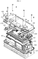
- FIG. 1 is an assembled perspective view schematically showing a structure of a secondary battery pack according to an embodiment
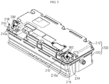
- FIG. 2 is a partially exploded perspective view of FIG. 1
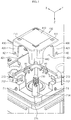
- FIG. 3 is a diagram showing a state in which a terminal cover is removed from a state of FIG. 1 .
- a secondary battery pack 10 includes a cell assembly 100, a pack case 200, an electrode terminal 300, and a terminal cover 400.
- the cell assembly 100 includes one or more secondary batteries.
- the cell assembly 100 may be an assembly including a plurality of secondary batteries.
- the plurality of secondary batteries may be pouch type secondary batteries.
- the pouch type secondary batteries may be configured to be stacked in a direction, e.g., in an up-and-down direction.
- the cell assembly 100 may further include a stacking frame 110.
- the stacking frame 110 is an element used to stack the secondary batteries, and holds the secondary batteries to prevent the secondary batteries from moving and is configured to be stackable to guide assembling of the secondary batteries.
- the stacking frame 110 may be expressed in other various terms such as a cartridge, etc., and may be configured as a square ring having empty center portion. In this case, four corners of the stacking frame 110 may be respectively located at an outer circumference of the pouch type secondary battery.
- the secondary battery pack 10 may further include a sensing unit 500 and electrical equipment 600.
- the sensing unit 500 transmits sensing information about electric characteristics such as a voltage of the secondary battery to a device such as BMS.
- the BMS may control the secondary batteries based on voltage information transmitted from the sensing unit 500.
- the sensing unit 500 may be mounted on the stacking frames 110 as shown in FIG. 2 , so as to be electrically connected to electrode leads of the plurality of secondary batteries.
- the electrical equipment 600 may include at least one of a BMS, a current sensor, a relay, and a fuse.
- the BMS battery management system
- the BMS is an element generally included in the secondary battery pack 10.
- a current sensor is an element for sensing charging/discharging currents of the secondary battery pack 10
- a relay is a switching component for selectively opening/closing charging/discharging current paths through which charging/discharging currents of the secondary battery pack 10 flow.
- a fuse is provided on the charging/discharging paths of the secondary battery pack 10 and blocks flow of the charging/discharging currents when an abnormal situation occurs in the secondary battery pack 10.
- the current sensor, the relay, and the fuse may exchange information with the BMS, and may be controlled by the BMS.
- the above electrical equipment 600 may be arranged on an upper portion of the stacking frames 110.
- the pack case 200 includes an internal space that is empty therein to accommodate the cell assembly 100, the sensing unit 500, and the electrical equipment 600 in the internal space.
- the pack case 200 may function as an exterior material of the secondary battery pack 10, and thus, the pack case 200 provides structural stability to the secondary battery pack 10 and protects the components such as the cell assembly 100 accommodated therein against external physical elements such as shock, impurities, etc.
- the pack case 200 may include a lower case 220 and an upper case 210, as shown in FIGS. 1 to 3 .
- the lower case 220 may have an open upper portion and an accommodation space therein, and the upper case 210 may be configured to cover the open upper portion of the lower case 220.
- the lower case 220 and the upper case 210 may be coupled to each other when boundaries thereof are coupled to each other via a coupling member such as a bolt.
- the pack case 200 has a square-shaped upper surface, two of four corners of which include terminal cover mounting parts 210a that are depressed from the upper surface of the pack case 200.
- the terminal cover mounting parts 210a are provided at the outermost corners on an upper surface of the upper case 210, and thus, the terminal cover mounting part 210a may have open outer surfaces and inner side surfaces surrounded by wall surfaces having a predetermined height.
- the terminal cover mounting part 210a includes a through hole 211 formed in a longitudinal direction.
- the pack case of the present embodiment may be configured so that the electrode terminal 300 may expose to an outer part of the upper case 210 via the through hole 211 of the terminal cover mounting part 210a when the upper case 210 and the lower case 220 are coupled to each other.
- the electrode terminal 300 is connected to the cell assembly 100 to provide a terminal that allows the cell assembly 100 to be electrically connected to an external device.
- the electrode terminal 300 may be directly or indirectly connected to electrode leads of the secondary batteries included in the cell assembly 100.
- the electrode terminal 300 may be electrically connected to the electrode lead of the secondary battery via a bus bar.
- the electrode terminal 300 may be exposed to the outer part of the pack case 200 as described above, in a state of connecting to the cell assembly 100.
- Two electrode terminals 300 may be included in the secondary battery pack 10.
- one electrode terminal 300 may function as a positive electrode terminal and the other electrode terminal 300 may function as a negative electrode terminal.
- the electrode terminal 300 may include a positive electrode terminal and a negative electrode terminal, and in this case, the positive electrode terminal is connected to a positive electrode lead of the secondary battery included in the cell assembly 100 and the negative electrode terminal may be connected to a negative electrode lead of the secondary battery.
- the electrode terminal 300 may protrude as shown in the drawing.
- a connecting operation may be easily performed and a connecting structure may be simplified.
- a connecting structure may be simplified.
- the electrode terminal 300 protrudes upward as in the above embodiment, an operator may easily perform a connecting operation of a cable to the electrode terminal 300 from the upper portion of the secondary battery pack 10.
- the terminal cover 400 is attachable to and detachable from the terminal cover mounting parts 210a to cover an upper portion and a part of a side surface of the electrode terminal 300. That is, the electrode terminal 300 may protrude to the outer part of the pack case 200, and in this case, the terminal cover 400 may cover the electrode terminal 300 except for a part, so that only a part may be exposed outside and remaining part may not be exposed.
- an opening part of the terminal cover 400 may be used as a passage of a cable (not shown) connected to the electrode terminal 300.
- the exposure of the electrode terminal 300 to the outside may be reduced.
- problems caused by the exposure of the electrode terminal 300 e.g., contacting of a metal material to the electrode terminal 300 and occurrence of an internal short-circuit, spark, a fire, etc., may be effectively prevented.
- FIG. 4 is a partially enlarged perspective view of a part A of FIG. 1
- FIG. 5 is a perspective view showing a state in which the terminal cover 400 is separated in FIG. 4
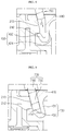
- FIG. 6 is a top view of FIG. 4
- FIG. 7 is a cross-sectional view taken along a line I-I' of FIG. 6 .
- the terminal cover 400 includes an upper plate 410 covering an upper part of the electrode terminal 300 and side plates 420 partially covering side surfaces of the electrode terminal 300.
- the electrode terminal 300 may be shielded except for a front side surface and a right side surface thereof in the drawings.
- the front side surface denotes a side surface right in front of the electrode terminal 300 and the right side surface is a side surface at right of the electrode terminal 300 when the secondary battery pack 10 is seen in a direction of an arrow B as shown in FIG. 1 .
- a rear side surface and a left side surface of the electrode terminal 300 may be blocked by wall surfaces of the terminal cover mounting part 210a.
- Each side plate 420 of the terminal cover 400 includes a cut portion 421 that is partially cut.
- two cut portions 421 are provided in the terminal cover 400 in different directions.
- One of the two cut portions 421 may be used as a passage for the cable wiring, and at this time, the operator may select one of the cut portions 421, which is suitable for the operation of wiring the cable.
- a location of another secondary battery pack 10 or an external device that has to be electrically connected to the secondary battery pack 10 in the drawings may be relatively changed, and thus an accessing direction or an extending direction of the cable for the electric connection between them may also vary.
- the terminal cover 400 includes the cut portions 421 respectively in the front side surface and the right side surface of the electrode terminal 300 in order to effectively deal with the variation in the cable connecting structure.
- the upper plate 410 of the terminal cover 400 is formed as a square corresponding to an upper area of the terminal cover mounting part 210a, and the side plates 420 correspond to two outer surfaces and have a height corresponding to that of the wall surface.
- the terminal cover 400 may be attached to/detached from the terminal cover mounting part 210a in a longitudinal direction.
- the terminal cover mounting part 210a and the terminal cover 400 respectively include a stopper 212 and a hooking protrusion 430 that are configured to hook-coupled to each other.
- the stopper 212 may be provided by partially depressing inward the wall surface of the terminal cover mounting part 210a, as shown in FIG. 5 .
- an inclined surface 213 is formed right on the stopper 212, and the inclined surface 213 guides the hooking protrusion 430 downward to be hook-coupled by the stopper 212 when the terminal cover 400 is attached.
- the hooking protrusion 430 is located at an inner space of the side plates 420 of the terminal cover 400 to extend downward from the upper plate 410 of the terminal cover 400, and may be configured to be hooked by the stopper 212 from upper and lower portions of each other.
- the hooking protrusion 430 may include a supporter 431 spaced a predetermined distance d from the stopper 212 in a transverse direction and extending vertically downward from the upper plate 410 of the terminal cover 400, and a coupling portion 432 curved upward from an end of the supporter 431 in a direction towards the hooking protrusion 212 to contact the stopper 212.
- the hooking protrusion 430 is formed on the upper plate 410 of the terminal cover 400 as a cantilever, and the supporter 431 is elastic to be curved within a predetermined range by an external force.
- Two stoppers 212 and two hooking protrusions 430 may be respectively provided on the terminal cover mounting part 210a and the terminal cover 400, and directions in which the two stoppers 430 are hook-coupled by the corresponding hooking protrusions 212 are different from each other.
- two stoppers 212 may be respectively formed on two crossing wall surfaces of the terminal cover mounting part 210a, and one of the two hooking protrusions 430 corresponding to the stoppers 212 is coupled to one stopper 212 in an X-axis direction of FIG. 4 and the other hooking protrusion 430 is coupled to the other stopper 212 in a Y-axis direction of FIG. 4 .
- the hook-coupled states in the X-axis and Y-axis directions have to be unhooked at the same time to separate the terminal cover 400. That is, the terminal cover 400 may be stably fixed to the upper case 210 to protect the electrode terminal 300.
- the present disclosure is not limited to the example, in which one stopper 212 is provided on one side wall of the terminal cover mounting part 210a and one hooking protrusion 430 corresponds to the stopper 212. That is, one or more pairs of stoppers 212 and hooking protrusions 430 may be respectively coupled to each other in different directions.
- the terminal cover mounting part 210a includes at least one of a protrusion and a groove
- the terminal cover 400 includes at least one of a groove and a protrusion corresponding to those of the terminal cover mounting parts 210a.
- the terminal cover mounting part 210a may further include first protrusions P1 protruding from the external surface thereof, and second grooves H1 formed as concavo-convex structures along upper boundaries of the wall surfaces.
- first grooves H2 engaged with the first protrusions and second protrusions engaged with the second grooves may be respectively provided in lower ends of the side plates 420 and opposite side surfaces of the terminal cover 400, which are not seen in the drawings.
- the terminal cover 400 may be held by the upper case 210 and may be restricted to move back and forth, and to left and right.
- the terminal cover 400 further includes a concave portion 440 at a corner where the side plates 420 cross each other.
- the concave portion 440 has a structure of being depressed or curved towards the inner portion of the terminal cover 400 between the two side plates 420.
- the terminal cover mounting part 210a includes an internal column 214 that is located in an internal area of the terminal cover 400 based on the concave portion 440 to support the upper plate 410 of the terminal cover 400, and an external column 215 provided to be inserted to the concave portion 440 in a longitudinal direction at an outer part of the terminal cover 400.
- the internal column 214 supports the upper plate 410 of the terminal cover 400 at the internal area of the terminal cover 400 to provide the terminal cover 400 with mechanical supporting force
- the external column 215 guides the mounting operation of the terminal cover 400 in the longitudinal direction and supports the terminal cover 400 at the outer part by being inserted into the internal space of the concave portion 440 to prevent the terminal cover 400 from moving in the transverse direction as shown in FIG. 6 .
- the terminal cover 400 may further include a jig hole 411 in the upper plate 410 of the terminal cover 400.
- the jig hole 411 is a hole provided to guide insertion of a cover separating jig 700 from the outer part of the terminal cover 400 into the terminal cover 400.
- the cover separating jig 700 (see FIG. 9 ) may be a bar-shaped tool for releasing the hooking protrusion 430 that has been hook-coupled in the internal area of the terminal cover 400 from the stopper 212.
- the hooking protrusion 430 may be separated from the stopper 212 when it is pushed by the cover separating jig 700 that is inserted through the jig hole 411, and the engagement in the longitudinal direction may be released. That is, two jig holes 411 are formed in the upper plate 410 of the terminal cover 400, and the cover separating jig 700 is inserted into each of the jig holes 411 to release the hook-coupling state of the hooking protrusion 430 from the stopper 212 and then the terminal cover 400 is lifted to be detached from the upper case 210.
- FIGS. 8 and 9 are partially enlarged views showing the terminal cover 400 before and after inserting the cover separating jig 700.
- the jig hole 411 may be located above a coupling portion 432.
- the cover separating jig 700 may be introduced to the internal space of the terminal cover 400, that is, a space between the stopper 212 and the supporter 431 of the hooking protrusion 430, through the jig hole 411.
- the jig hole 411 may be formed in the upper plate 410 of the terminal cover 400 to be inclined by a predetermined angle ( ⁇ ) with respect to a vertical direction.
- the upper plate 410 of the terminal cover 400 has a predetermined thickness, and the upper plate 410 is perforated in an inclined state by a predetermined angle to form the jig hole 411.
- the inclined direction of the jig hole 411 may face the supporter 431 of the hooking protrusion 430.
- the cover separating jig 700 may be inserted in a direction C to be inclined by a predetermined angle with respect to the upper plate 410, and the hooking protrusion 430 is elastically curved in a direction D and released from the stopper 212 when the cover separating jig 700 pushes the hooking protrusion 430.
- the cover separating jig 700 may include a compressor 720 that may pass through the jig hole 411 and a head 710 that may not be inserted to the jig hole 411. That is, the compressor 720 is integrally formed with the head 710, and has a smaller cross-sectional area than the head 710. In addition, the jig hole 411 may have a diameter that only allows the compressor 720 to be inserted therein.
- a length of the compressor 720 may be determined to correspond to an elastic deformation value of the hooking protrusion 430, which makes the hooking protrusion 430 separated from the stopper 212. By restricting the length and the insertion depth of the compressor 720, an excessive power may not be applied to the hooking protrusion 430, and thereby damage on the components may be prevented.
- the pack case 200 and the terminal cover 400 may be easily attached to/detached from each other and a coupling force therebetween may be improved comparing with the related art, and thus, safety of the secondary battery pack 10 may be improved.
- the coupling state between the hooking protrusion 430 of the terminal cover 400 and the stopper 212 of the terminal cover mounting part 210a is to be released, and accordingly, a power having an accurate and appropriate strength may be applied to the coupling portion. Therefore, anyone may separate the terminal cover 400 from the pack case 200 without concerning about the breakdown of the components.
- a vehicle according to the present disclosure may include the secondary battery pack 10 according to the present disclosure.
- the secondary battery pack 10 may be applied to a vehicle such as an electric vehicle or a hybrid car, and moreover, may be also applied to information technology (IT) products.
- IT information technology
Claims (10)
- Sekundärbatteriepack (10), umfassend:eine Zellenanordnung (100), umfassend eine Mehrzahl von Sekundärbatterien;ein Packgehäuse (200), welches einen Innenraum zum Aufnehmen der Zellenanordnung (100) aufweist und einen Anschlussabdeckung-Montageteil (210a) umfasst, welcher eine quadratisch geformte obere Fläche und vier Ecken aufweist, von welchen wenigstens eine vertieft ist;einen Elektrodenanschluss (300), welcher mit der Zellenanordnung (100) verbunden ist und zu einer Außenseite des Packgehäuses (200) hin vorsteht und an dem Anschlussabdeckung-Montageteil (210a) angeordnet ist, welcher ein Durchgangsloch (211) umfasst, welches in einer vertikalen Richtung bereitgestellt ist, so dass der Elektrodenanschluss (300) zu der Außenseite hin vorsteht; undeine Anschlussabdeckung (400), welche dazu eingerichtet ist, einen oberen Abschnitt und Teilseitenflächen des Elektrodenanschlusses (300) zu bedecken und abnehmbar von dem Packgehäuse (200) zu sein, indem sie einen Hakenvorsprung (430) umfasst, welcher hakengekoppelt mit und freigegeben von einem Anschlag (212) ist, der in dem Packgehäuse (200) bereitgestellt ist, und mit dem Anschlussabdeckung-Montageteil (210a) gekoppelt ist,wobei die Anschlussabdeckung (400) ferner ein Vorrichtungsloch (411), welches dazu eingerichtet ist, einer Abdeckung-Trennvorrichtung (700) zu erlauben, von außen her nach innen eingesetzt zu werden, und der Hakenvorsprung (430) an einem inneren Bereich der Anschlussabdeckung (400) bereitgestellt ist, welcher von dem Anschlag (212) freizugeben ist, wenn die Abdeckung-Trennvorrichtung (700), welche durch das Vorrichtungsloch (411) eingesetzt ist, den Hakenvorsprung (430) drückt, und eine obere Platte (410), welche einen oberen Abschnitt des Elektrodenanschlusses (300) bedeckt, und Seitenplatten (420) umfasst, welche Seitenflächen des Elektrodenanschlusses (300) teilweise bedecken, und wobeidie Anschlussabdeckung (400) einen konkaven Abschnitt (440) umfasst, welcher durch Vertiefen einer Ecke, an welcher die beiden Seitenplatten einander kreuzen, in einen inneren Bereich der Anschlussabdeckung (400) gebildet ist, undder Anschlussabdeckung-Montageteil (210a) eine innere Säule (214), welche an einem inneren Bereich der Anschlussabdeckung (400) basierend auf dem konkaven Abschnitt (440) angeordnet ist, um die obere Platte (410) der Anschlussabdeckung (400) zu haltern, und eine äußere Säule (215) umfasst, welche bereitgestellt ist, um von einem äußeren Teil der Anschlussabdeckung (400) her in einer longitudinalen Richtung in den konkaven Abschnitt (440) eingesetzt zu sein.
- Sekundärbatteriepack (10) nach Anspruch 1, wobei sich der Hakenvorsprung (430) von der oberen Platte (410) der Anschlussabdeckung (400) nach unten erstreckt und der Anschlag (212) von einer Wandfläche des Anschlussabdeckung-Montageteils (210a) teilweise nach innen vertieft ist.
- Sekundärbatteriepack (10) nach Anspruch 2, wobei der Anschlag (212) jeweils an zwei kreuzenden Wandflächen des Anschlussabdeckung-Montageteils (210a) zwei Anschläge umfasst und der Hakenvorsprung (430) zwei Hakenvorsprünge umfasst, welche den beiden Anschlägen entsprechen, und die beiden Hakenvorsprünge in verschiedenen Richtungen mit den beiden Anschlägen hakengekoppelt sind.
- Sekundärbatteriepack (10) nach Anspruch 2, wobei der Hakenvorsprung (430) und der Anschlag (212) derart eingerichtet sind, dass sie vertikal miteinander hakengekoppelt sind.
- Sekundärbatteriepack (10) nach Anspruch 2, wobei eine geneigte Fläche, die den Hakenvorsprung (430) derart nach unten führt, dass er hakengekoppelt mit dem Anschlag (212) ist, an einem oberen Teil des Anschlags (212) gebildet ist.
- Sekundärbatteriepack (10) nach Anspruch 2, wobei der Hakenvorsprung (430) umfasst:eine Halterung (431), welche in einer transversalen Richtung um einen vorbestimmten Abstand (d) von dem Anschlag (212) beabstandet ist und sich von der oberen Platte (410) der Anschlussabdeckung (400) her rechtwinklig nach unten erstreckt; undeinen Kopplungsabschnitt (432), welcher von einem Ende der Halterung (431) her in einer Richtung in Richtung des Anschlags (212) nach oben gekrümmt ist, um den Anschlag (212) zu berühren, undwobei das Vorrichtungsloch (411) oberhalb des Kopplungsabschnitts (432) positioniert ist.
- Sekundärbatteriepack (10) nach Anspruch 1, wobei der Anschlussabdeckung-Montageteil (210a) wenigstens eines aus einem Vorsprung und einer Nut umfasst und die Anschlussabdeckung (400) wenigstens eines aus einer Nut und einem Vorsprung umfasst, welches dem Anschlussabdeckung-Montageteil (210a) entspricht.
- Sekundärbatteriepack (10) nach Anspruch 1, wobei der Elektrodenanschluss (300) einen positiven Elektrodenanschluss und einen negativen Elektrodenanschluss umfasst und die Anschlussabdeckung (400) zwei Anschlussabdeckungen umfasst, welche jeweils den positiven Elektrodenanschluss und den negativen Elektrodenanschluss bedecken.
- Sekundärbatteriepack (10) nach Anspruch 1, wobei die Abdeckung-Trennvorrichtung (700) einen Kopf (710) und ein Kompressionselement (720) umfasst, welches sich von dem Kopf (710) her erstreckt und eine kleinere Querschnittsfläche als der Kopf (710) aufweist, und das Vorrichtungsloch gleich wie oder größer als eine Querschnittsfläche des Kompressionselements und kleiner als eine Querschnittsfläche des Kopfes ist.
- Fahrzeug, umfassend den Sekundärbatteriepack (10) nach einem der Ansprüche 1 bis 9.
Priority Applications (1)
| Application Number | Priority Date | Filing Date | Title |
|---|---|---|---|
| PL16875910T PL3306702T3 (pl) | 2015-12-18 | 2016-11-02 | Pakiet baterii akumulatorowych |
Applications Claiming Priority (2)
| Application Number | Priority Date | Filing Date | Title |
|---|---|---|---|
| KR1020150181751A KR102065106B1 (ko) | 2015-12-18 | 2015-12-18 | 이차전지 팩 |
| PCT/KR2016/012527 WO2017104968A1 (ko) | 2015-12-18 | 2016-11-02 | 이차전지 팩 |
Publications (3)
| Publication Number | Publication Date |
|---|---|
| EP3306702A1 EP3306702A1 (de) | 2018-04-11 |
| EP3306702A4 EP3306702A4 (de) | 2018-06-06 |
| EP3306702B1 true EP3306702B1 (de) | 2020-06-17 |
Family
ID=59056866
Family Applications (1)
| Application Number | Title | Priority Date | Filing Date |
|---|---|---|---|
| EP16875910.8A Active EP3306702B1 (de) | 2015-12-18 | 2016-11-02 | Sekundärbatteriepack |
Country Status (7)
| Country | Link |
|---|---|
| US (1) | US11374277B2 (de) |
| EP (1) | EP3306702B1 (de) |
| JP (1) | JP6619087B2 (de) |
| KR (1) | KR102065106B1 (de) |
| CN (1) | CN107851750B (de) |
| PL (1) | PL3306702T3 (de) |
| WO (1) | WO2017104968A1 (de) |
Families Citing this family (7)
| Publication number | Priority date | Publication date | Assignee | Title |
|---|---|---|---|---|
| HUE065059T2 (hu) | 2017-09-29 | 2024-04-28 | Robert Bosch Gmbh | Akkumulátorcsomag, beleértve a cellatartást is |
| KR102412941B1 (ko) * | 2018-01-19 | 2022-06-23 | 주식회사 엘지에너지솔루션 | 터미널 커버 및 이를 포함하는 배터리 팩 |
| KR102394740B1 (ko) * | 2018-08-09 | 2022-05-04 | 주식회사 엘지에너지솔루션 | 이차전지 충방전 장치 |
| DE102019109725B4 (de) * | 2019-04-12 | 2023-12-14 | Dr. Ing. H.C. F. Porsche Aktiengesellschaft | Batteriemodul und System aus Batterieverbinder und Batteriemodulen |
| KR102350763B1 (ko) * | 2020-04-29 | 2022-01-13 | (주)에디슨테크 | 배터리용 단자커버의 결합구조 |
| KR20220043543A (ko) * | 2020-09-29 | 2022-04-05 | 에스케이온 주식회사 | 단자대 보호 커버 및 이를 포함하는 배터리모듈 |
| EP4342019A2 (de) * | 2021-05-21 | 2024-03-27 | CPS Technology Holdings LLC | Batterieverbinder und batterieabdeckung |
Family Cites Families (19)
| Publication number | Priority date | Publication date | Assignee | Title |
|---|---|---|---|---|
| DE4300567A1 (de) * | 1993-01-12 | 1994-07-14 | Hagen Batterie Ag | Akkumulator mit die Pole verdeckender lösbarer Abdeckplatte |
| JPH10208719A (ja) * | 1997-01-28 | 1998-08-07 | Smk Corp | 電池収納部の蓋 |
| JP2001068082A (ja) * | 1999-08-25 | 2001-03-16 | Sousei Denshi:Kk | 電池ボックスの蓋 |
| JP4794736B2 (ja) | 2001-01-31 | 2011-10-19 | 古河電池株式会社 | 蓄電池の端子構造 |
| JP5197985B2 (ja) * | 2007-04-05 | 2013-05-15 | 日置電機株式会社 | 電池を備える携帯用器具 |
| KR101003962B1 (ko) * | 2010-03-15 | 2010-12-30 | 주식회사 대륙 | 배선용 차단기 |
| KR200461334Y1 (ko) | 2010-08-10 | 2012-07-06 | 세방전지(주) | 배터리의 터미널 커버 |
| WO2012066707A1 (ja) * | 2010-11-16 | 2012-05-24 | Necカシオモバイルコミュニケーションズ株式会社 | カバーのロック構造 |
| JP5762228B2 (ja) | 2011-09-13 | 2015-08-12 | 矢崎総業株式会社 | 車載バッテリ集合体用端子台 |
| KR102031387B1 (ko) | 2011-10-24 | 2019-10-11 | 다이아몬드 이노베이션즈, 인크. | 복수의 세장형 요소를 이용하여 2 개의 부품을 그들 사이의 축선방향 및 각도방향 정렬을 보장하도록 접합하는 방법 |
| KR102023916B1 (ko) | 2012-07-23 | 2019-09-23 | 에스케이이노베이션 주식회사 | 전지모듈의 전극단자 및 터미널 연결장치 |
| KR20140060633A (ko) | 2012-11-12 | 2014-05-21 | 주식회사 엘지화학 | 버스 바 어셈블리를 포함하는 전지모듈 및 이를 포함하는 전지팩 |
| JP6086315B2 (ja) * | 2013-03-19 | 2017-03-01 | 株式会社Gsユアサ | 蓄電装置 |
| EP2991132B1 (de) | 2013-05-15 | 2017-11-15 | Lg Chem, Ltd. | Batteriemodulbaugruppe |
| JP2014231132A (ja) | 2013-05-30 | 2014-12-11 | 日立工機株式会社 | 電気装置及び電気機器及び電池パック |
| KR101689750B1 (ko) | 2014-01-21 | 2016-12-26 | 주식회사 엘지화학 | 배터리 팩 |
| KR101808307B1 (ko) | 2014-05-28 | 2017-12-12 | 주식회사 엘지화학 | 단자 커버 및 이를 포함하는 배터리 팩 |
| KR101881196B1 (ko) * | 2015-06-16 | 2018-07-23 | 주식회사 엘지화학 | 전지 팩 |
| JP6128197B2 (ja) * | 2015-12-21 | 2017-05-17 | 株式会社Gsユアサ | 組電池、単電池、及びキャップ |
-
2015
- 2015-12-18 KR KR1020150181751A patent/KR102065106B1/ko active IP Right Grant
-
2016
- 2016-11-02 JP JP2018515996A patent/JP6619087B2/ja active Active
- 2016-11-02 US US15/735,324 patent/US11374277B2/en active Active
- 2016-11-02 EP EP16875910.8A patent/EP3306702B1/de active Active
- 2016-11-02 WO PCT/KR2016/012527 patent/WO2017104968A1/ko active Application Filing
- 2016-11-02 CN CN201680039918.4A patent/CN107851750B/zh active Active
- 2016-11-02 PL PL16875910T patent/PL3306702T3/pl unknown
Non-Patent Citations (1)
| Title |
|---|
| None * |
Also Published As
| Publication number | Publication date |
|---|---|
| WO2017104968A1 (ko) | 2017-06-22 |
| CN107851750B (zh) | 2020-11-03 |
| US20180175342A1 (en) | 2018-06-21 |
| KR20170073170A (ko) | 2017-06-28 |
| CN107851750A (zh) | 2018-03-27 |
| PL3306702T3 (pl) | 2021-03-08 |
| EP3306702A1 (de) | 2018-04-11 |
| KR102065106B1 (ko) | 2020-01-10 |
| EP3306702A4 (de) | 2018-06-06 |
| JP6619087B2 (ja) | 2019-12-11 |
| US11374277B2 (en) | 2022-06-28 |
| JP2018530874A (ja) | 2018-10-18 |
Similar Documents
| Publication | Publication Date | Title |
|---|---|---|
| EP3306702B1 (de) | Sekundärbatteriepack | |
| KR101127603B1 (ko) | 버스 바 홀더 및 이를 구비하는 배터리 팩 | |
| EP3285314B1 (de) | Sekundärbatteriepack | |
| CN111149236B (zh) | 电池组 | |
| CN112004643B (zh) | 用于制造电池组的栓接装置及其应用 | |
| EP2509135B1 (de) | Wiederaufladbare Batterie mit verbesserter Beständigkeit gegen externen Stössen und Vibrationen | |
| KR102441019B1 (ko) | 외부 단락 방지 구조가 적용된 배터리 모듈 | |
| CN111149234A (zh) | 电连接部件收纳壳体以及电池模块 | |
| KR102269112B1 (ko) | Bms 유동 방지용 댐핑부재 및 이를 포함하는 전지모듈 | |
| JP7459260B2 (ja) | 取外し可能なヒューズアセンブリーを備えるバッテリーモジュール及びそれを含むバッテリーパック | |
| JP7318137B2 (ja) | 取付座、電池および電気設備 | |
| KR20170083311A (ko) | 배터리 팩 | |
| KR102019472B1 (ko) | 배터리 모듈 및 이를 포함하는 배터리 팩 | |
| JP2017130289A (ja) | 蓄電装置 | |
| KR101808311B1 (ko) | 파워 케이블의 안정적 조립 및 전기적 노이즈 저감 구조를 구비한 배터리 팩 | |
| JP2017152161A (ja) | 蓄電装置 | |
| US20200091478A1 (en) | Energy storage apparatus | |
| CN110915018A (zh) | 电池组 | |
| KR102352625B1 (ko) | 외부 단락 방지 구조가 적용된 배터리 모듈을 이용한 배터리 팩 | |
| JP6772875B2 (ja) | 蓄電装置 | |
| KR20130003574A (ko) | 차량의 배터리팩용 프로텍터 | |
| US20220384920A1 (en) | Energy storage apparatus | |
| WO2021079938A1 (ja) | 蓄電設備 | |
| EP4322297A1 (de) | Batteriepack mit verbesserter stossfestigkeit | |
| CN115513610A (zh) | 电池包和包括电池包的车辆 |
Legal Events
| Date | Code | Title | Description |
|---|---|---|---|
| STAA | Information on the status of an ep patent application or granted ep patent |
Free format text: STATUS: THE INTERNATIONAL PUBLICATION HAS BEEN MADE |
|
| PUAI | Public reference made under article 153(3) epc to a published international application that has entered the european phase |
Free format text: ORIGINAL CODE: 0009012 |
|
| STAA | Information on the status of an ep patent application or granted ep patent |
Free format text: STATUS: REQUEST FOR EXAMINATION WAS MADE |
|
| 17P | Request for examination filed |
Effective date: 20180104 |
|
| AK | Designated contracting states |
Kind code of ref document: A1 Designated state(s): AL AT BE BG CH CY CZ DE DK EE ES FI FR GB GR HR HU IE IS IT LI LT LU LV MC MK MT NL NO PL PT RO RS SE SI SK SM TR |
|
| AX | Request for extension of the european patent |
Extension state: BA ME |
|
| A4 | Supplementary search report drawn up and despatched |
Effective date: 20180509 |
|
| RIC1 | Information provided on ipc code assigned before grant |
Ipc: H01M 2/10 20060101AFI20180430BHEP Ipc: H01M 2/30 20060101ALI20180430BHEP |
|
| DAV | Request for validation of the european patent (deleted) | ||
| DAX | Request for extension of the european patent (deleted) | ||
| GRAP | Despatch of communication of intention to grant a patent |
Free format text: ORIGINAL CODE: EPIDOSNIGR1 |
|
| STAA | Information on the status of an ep patent application or granted ep patent |
Free format text: STATUS: GRANT OF PATENT IS INTENDED |
|
| INTG | Intention to grant announced |
Effective date: 20200409 |
|
| GRAS | Grant fee paid |
Free format text: ORIGINAL CODE: EPIDOSNIGR3 |
|
| GRAA | (expected) grant |
Free format text: ORIGINAL CODE: 0009210 |
|
| STAA | Information on the status of an ep patent application or granted ep patent |
Free format text: STATUS: THE PATENT HAS BEEN GRANTED |
|
| AK | Designated contracting states |
Kind code of ref document: B1 Designated state(s): AL AT BE BG CH CY CZ DE DK EE ES FI FR GB GR HR HU IE IS IT LI LT LU LV MC MK MT NL NO PL PT RO RS SE SI SK SM TR |
|
| REG | Reference to a national code |
Ref country code: GB Ref legal event code: FG4D |
|
| REG | Reference to a national code |
Ref country code: CH Ref legal event code: EP |
|
| REG | Reference to a national code |
Ref country code: DE Ref legal event code: R096 Ref document number: 602016038502 Country of ref document: DE |
|
| REG | Reference to a national code |
Ref country code: IE Ref legal event code: FG4D |
|
| REG | Reference to a national code |
Ref country code: AT Ref legal event code: REF Ref document number: 1282422 Country of ref document: AT Kind code of ref document: T Effective date: 20200715 |
|
| PG25 | Lapsed in a contracting state [announced via postgrant information from national office to epo] |
Ref country code: LT Free format text: LAPSE BECAUSE OF FAILURE TO SUBMIT A TRANSLATION OF THE DESCRIPTION OR TO PAY THE FEE WITHIN THE PRESCRIBED TIME-LIMIT Effective date: 20200617 Ref country code: FI Free format text: LAPSE BECAUSE OF FAILURE TO SUBMIT A TRANSLATION OF THE DESCRIPTION OR TO PAY THE FEE WITHIN THE PRESCRIBED TIME-LIMIT Effective date: 20200617 Ref country code: GR Free format text: LAPSE BECAUSE OF FAILURE TO SUBMIT A TRANSLATION OF THE DESCRIPTION OR TO PAY THE FEE WITHIN THE PRESCRIBED TIME-LIMIT Effective date: 20200918 Ref country code: SE Free format text: LAPSE BECAUSE OF FAILURE TO SUBMIT A TRANSLATION OF THE DESCRIPTION OR TO PAY THE FEE WITHIN THE PRESCRIBED TIME-LIMIT Effective date: 20200617 Ref country code: NO Free format text: LAPSE BECAUSE OF FAILURE TO SUBMIT A TRANSLATION OF THE DESCRIPTION OR TO PAY THE FEE WITHIN THE PRESCRIBED TIME-LIMIT Effective date: 20200917 |
|
| REG | Reference to a national code |
Ref country code: LT Ref legal event code: MG4D |
|
| REG | Reference to a national code |
Ref country code: NL Ref legal event code: MP Effective date: 20200617 |
|
| REG | Reference to a national code |
Ref country code: DE Ref legal event code: R079 Ref document number: 602016038502 Country of ref document: DE Free format text: PREVIOUS MAIN CLASS: H01M0002100000 Ipc: H01M0050200000 |
|
| PG25 | Lapsed in a contracting state [announced via postgrant information from national office to epo] |
Ref country code: BG Free format text: LAPSE BECAUSE OF FAILURE TO SUBMIT A TRANSLATION OF THE DESCRIPTION OR TO PAY THE FEE WITHIN THE PRESCRIBED TIME-LIMIT Effective date: 20200917 Ref country code: HR Free format text: LAPSE BECAUSE OF FAILURE TO SUBMIT A TRANSLATION OF THE DESCRIPTION OR TO PAY THE FEE WITHIN THE PRESCRIBED TIME-LIMIT Effective date: 20200617 Ref country code: RS Free format text: LAPSE BECAUSE OF FAILURE TO SUBMIT A TRANSLATION OF THE DESCRIPTION OR TO PAY THE FEE WITHIN THE PRESCRIBED TIME-LIMIT Effective date: 20200617 Ref country code: LV Free format text: LAPSE BECAUSE OF FAILURE TO SUBMIT A TRANSLATION OF THE DESCRIPTION OR TO PAY THE FEE WITHIN THE PRESCRIBED TIME-LIMIT Effective date: 20200617 |
|
| REG | Reference to a national code |
Ref country code: AT Ref legal event code: MK05 Ref document number: 1282422 Country of ref document: AT Kind code of ref document: T Effective date: 20200617 |
|
| PG25 | Lapsed in a contracting state [announced via postgrant information from national office to epo] |
Ref country code: AL Free format text: LAPSE BECAUSE OF FAILURE TO SUBMIT A TRANSLATION OF THE DESCRIPTION OR TO PAY THE FEE WITHIN THE PRESCRIBED TIME-LIMIT Effective date: 20200617 Ref country code: NL Free format text: LAPSE BECAUSE OF FAILURE TO SUBMIT A TRANSLATION OF THE DESCRIPTION OR TO PAY THE FEE WITHIN THE PRESCRIBED TIME-LIMIT Effective date: 20200617 |
|
| PG25 | Lapsed in a contracting state [announced via postgrant information from national office to epo] |
Ref country code: EE Free format text: LAPSE BECAUSE OF FAILURE TO SUBMIT A TRANSLATION OF THE DESCRIPTION OR TO PAY THE FEE WITHIN THE PRESCRIBED TIME-LIMIT Effective date: 20200617 Ref country code: AT Free format text: LAPSE BECAUSE OF FAILURE TO SUBMIT A TRANSLATION OF THE DESCRIPTION OR TO PAY THE FEE WITHIN THE PRESCRIBED TIME-LIMIT Effective date: 20200617 Ref country code: SM Free format text: LAPSE BECAUSE OF FAILURE TO SUBMIT A TRANSLATION OF THE DESCRIPTION OR TO PAY THE FEE WITHIN THE PRESCRIBED TIME-LIMIT Effective date: 20200617 Ref country code: ES Free format text: LAPSE BECAUSE OF FAILURE TO SUBMIT A TRANSLATION OF THE DESCRIPTION OR TO PAY THE FEE WITHIN THE PRESCRIBED TIME-LIMIT Effective date: 20200617 Ref country code: CZ Free format text: LAPSE BECAUSE OF FAILURE TO SUBMIT A TRANSLATION OF THE DESCRIPTION OR TO PAY THE FEE WITHIN THE PRESCRIBED TIME-LIMIT Effective date: 20200617 Ref country code: RO Free format text: LAPSE BECAUSE OF FAILURE TO SUBMIT A TRANSLATION OF THE DESCRIPTION OR TO PAY THE FEE WITHIN THE PRESCRIBED TIME-LIMIT Effective date: 20200617 Ref country code: PT Free format text: LAPSE BECAUSE OF FAILURE TO SUBMIT A TRANSLATION OF THE DESCRIPTION OR TO PAY THE FEE WITHIN THE PRESCRIBED TIME-LIMIT Effective date: 20201019 Ref country code: IT Free format text: LAPSE BECAUSE OF FAILURE TO SUBMIT A TRANSLATION OF THE DESCRIPTION OR TO PAY THE FEE WITHIN THE PRESCRIBED TIME-LIMIT Effective date: 20200617 |
|
| PG25 | Lapsed in a contracting state [announced via postgrant information from national office to epo] |
Ref country code: SK Free format text: LAPSE BECAUSE OF FAILURE TO SUBMIT A TRANSLATION OF THE DESCRIPTION OR TO PAY THE FEE WITHIN THE PRESCRIBED TIME-LIMIT Effective date: 20200617 Ref country code: IS Free format text: LAPSE BECAUSE OF FAILURE TO SUBMIT A TRANSLATION OF THE DESCRIPTION OR TO PAY THE FEE WITHIN THE PRESCRIBED TIME-LIMIT Effective date: 20201017 |
|
| REG | Reference to a national code |
Ref country code: DE Ref legal event code: R097 Ref document number: 602016038502 Country of ref document: DE |
|
| PLBE | No opposition filed within time limit |
Free format text: ORIGINAL CODE: 0009261 |
|
| STAA | Information on the status of an ep patent application or granted ep patent |
Free format text: STATUS: NO OPPOSITION FILED WITHIN TIME LIMIT |
|
| PG25 | Lapsed in a contracting state [announced via postgrant information from national office to epo] |
Ref country code: DK Free format text: LAPSE BECAUSE OF FAILURE TO SUBMIT A TRANSLATION OF THE DESCRIPTION OR TO PAY THE FEE WITHIN THE PRESCRIBED TIME-LIMIT Effective date: 20200617 |
|
| 26N | No opposition filed |
Effective date: 20210318 |
|
| PG25 | Lapsed in a contracting state [announced via postgrant information from national office to epo] |
Ref country code: SI Free format text: LAPSE BECAUSE OF FAILURE TO SUBMIT A TRANSLATION OF THE DESCRIPTION OR TO PAY THE FEE WITHIN THE PRESCRIBED TIME-LIMIT Effective date: 20200617 |
|
| PG25 | Lapsed in a contracting state [announced via postgrant information from national office to epo] |
Ref country code: MC Free format text: LAPSE BECAUSE OF FAILURE TO SUBMIT A TRANSLATION OF THE DESCRIPTION OR TO PAY THE FEE WITHIN THE PRESCRIBED TIME-LIMIT Effective date: 20200617 |
|
| REG | Reference to a national code |
Ref country code: CH Ref legal event code: PL |
|
| PG25 | Lapsed in a contracting state [announced via postgrant information from national office to epo] |
Ref country code: LU Free format text: LAPSE BECAUSE OF NON-PAYMENT OF DUE FEES Effective date: 20201102 |
|
| REG | Reference to a national code |
Ref country code: BE Ref legal event code: MM Effective date: 20201130 |
|
| PG25 | Lapsed in a contracting state [announced via postgrant information from national office to epo] |
Ref country code: LI Free format text: LAPSE BECAUSE OF NON-PAYMENT OF DUE FEES Effective date: 20201130 Ref country code: CH Free format text: LAPSE BECAUSE OF NON-PAYMENT OF DUE FEES Effective date: 20201130 |
|
| PG25 | Lapsed in a contracting state [announced via postgrant information from national office to epo] |
Ref country code: IE Free format text: LAPSE BECAUSE OF NON-PAYMENT OF DUE FEES Effective date: 20201102 |
|
| PG25 | Lapsed in a contracting state [announced via postgrant information from national office to epo] |
Ref country code: TR Free format text: LAPSE BECAUSE OF FAILURE TO SUBMIT A TRANSLATION OF THE DESCRIPTION OR TO PAY THE FEE WITHIN THE PRESCRIBED TIME-LIMIT Effective date: 20200617 Ref country code: MT Free format text: LAPSE BECAUSE OF FAILURE TO SUBMIT A TRANSLATION OF THE DESCRIPTION OR TO PAY THE FEE WITHIN THE PRESCRIBED TIME-LIMIT Effective date: 20200617 Ref country code: CY Free format text: LAPSE BECAUSE OF FAILURE TO SUBMIT A TRANSLATION OF THE DESCRIPTION OR TO PAY THE FEE WITHIN THE PRESCRIBED TIME-LIMIT Effective date: 20200617 |
|
| PG25 | Lapsed in a contracting state [announced via postgrant information from national office to epo] |
Ref country code: MK Free format text: LAPSE BECAUSE OF FAILURE TO SUBMIT A TRANSLATION OF THE DESCRIPTION OR TO PAY THE FEE WITHIN THE PRESCRIBED TIME-LIMIT Effective date: 20200617 |
|
| PG25 | Lapsed in a contracting state [announced via postgrant information from national office to epo] |
Ref country code: BE Free format text: LAPSE BECAUSE OF NON-PAYMENT OF DUE FEES Effective date: 20201130 |
|
| REG | Reference to a national code |
Ref country code: DE Ref legal event code: R081 Ref document number: 602016038502 Country of ref document: DE Owner name: LG ENERGY SOLUTION, LTD., KR Free format text: FORMER OWNER: LG CHEM, LTD., SEOUL, KR |
|
| P01 | Opt-out of the competence of the unified patent court (upc) registered |
Effective date: 20230512 |
|
| REG | Reference to a national code |
Ref country code: GB Ref legal event code: 732E Free format text: REGISTERED BETWEEN 20230824 AND 20230831 |
|
| PGFP | Annual fee paid to national office [announced via postgrant information from national office to epo] |
Ref country code: GB Payment date: 20231023 Year of fee payment: 8 |
|
| PGFP | Annual fee paid to national office [announced via postgrant information from national office to epo] |
Ref country code: FR Payment date: 20231024 Year of fee payment: 8 Ref country code: DE Payment date: 20231023 Year of fee payment: 8 |
|
| PGFP | Annual fee paid to national office [announced via postgrant information from national office to epo] |
Ref country code: PL Payment date: 20231024 Year of fee payment: 8 |