EP3306702B1 - Secondary battery pack - Google Patents
Secondary battery pack Download PDFInfo
- Publication number
- EP3306702B1 EP3306702B1 EP16875910.8A EP16875910A EP3306702B1 EP 3306702 B1 EP3306702 B1 EP 3306702B1 EP 16875910 A EP16875910 A EP 16875910A EP 3306702 B1 EP3306702 B1 EP 3306702B1
- Authority
- EP
- European Patent Office
- Prior art keywords
- terminal cover
- terminal
- secondary battery
- battery pack
- stopper
- Prior art date
- Legal status (The legal status is an assumption and is not a legal conclusion. Google has not performed a legal analysis and makes no representation as to the accuracy of the status listed.)
- Active
Links
- 238000010168 coupling process Methods 0.000 claims description 17
- 238000005859 coupling reaction Methods 0.000 claims description 17
- 230000008878 coupling Effects 0.000 claims description 16
- 230000000994 depressogenic effect Effects 0.000 claims description 6
- 230000000881 depressing effect Effects 0.000 claims description 3
- 238000007599 discharging Methods 0.000 description 7
- 238000000034 method Methods 0.000 description 4
- 238000010586 diagram Methods 0.000 description 3
- 239000004020 conductor Substances 0.000 description 2
- 238000003780 insertion Methods 0.000 description 2
- 230000037431 insertion Effects 0.000 description 2
- 239000000463 material Substances 0.000 description 2
- OKTJSMMVPCPJKN-UHFFFAOYSA-N Carbon Chemical compound [C] OKTJSMMVPCPJKN-UHFFFAOYSA-N 0.000 description 1
- 230000002159 abnormal effect Effects 0.000 description 1
- 230000004308 accommodation Effects 0.000 description 1
- 229910052799 carbon Inorganic materials 0.000 description 1
- 230000015556 catabolic process Effects 0.000 description 1
- 230000001419 dependent effect Effects 0.000 description 1
- 230000000694 effects Effects 0.000 description 1
- 230000005489 elastic deformation Effects 0.000 description 1
- 238000005516 engineering process Methods 0.000 description 1
- 239000012535 impurity Substances 0.000 description 1
- 238000012423 maintenance Methods 0.000 description 1
- 239000002184 metal Substances 0.000 description 1
- 239000007769 metal material Substances 0.000 description 1
- 238000012986 modification Methods 0.000 description 1
- 230000004048 modification Effects 0.000 description 1
- 238000000926 separation method Methods 0.000 description 1
- 230000035939 shock Effects 0.000 description 1
Images


Classifications
-
- H—ELECTRICITY
- H01—ELECTRIC ELEMENTS
- H01M—PROCESSES OR MEANS, e.g. BATTERIES, FOR THE DIRECT CONVERSION OF CHEMICAL ENERGY INTO ELECTRICAL ENERGY
- H01M10/00—Secondary cells; Manufacture thereof
- H01M10/04—Construction or manufacture in general
- H01M10/045—Cells or batteries with folded plate-like electrodes
-
- H—ELECTRICITY
- H01—ELECTRIC ELEMENTS
- H01M—PROCESSES OR MEANS, e.g. BATTERIES, FOR THE DIRECT CONVERSION OF CHEMICAL ENERGY INTO ELECTRICAL ENERGY
- H01M50/00—Constructional details or processes of manufacture of the non-active parts of electrochemical cells other than fuel cells, e.g. hybrid cells
- H01M50/20—Mountings; Secondary casings or frames; Racks, modules or packs; Suspension devices; Shock absorbers; Transport or carrying devices; Holders
- H01M50/204—Racks, modules or packs for multiple batteries or multiple cells
- H01M50/207—Racks, modules or packs for multiple batteries or multiple cells characterised by their shape
- H01M50/211—Racks, modules or packs for multiple batteries or multiple cells characterised by their shape adapted for pouch cells
-
- H—ELECTRICITY
- H01—ELECTRIC ELEMENTS
- H01M—PROCESSES OR MEANS, e.g. BATTERIES, FOR THE DIRECT CONVERSION OF CHEMICAL ENERGY INTO ELECTRICAL ENERGY
- H01M50/00—Constructional details or processes of manufacture of the non-active parts of electrochemical cells other than fuel cells, e.g. hybrid cells
- H01M50/20—Mountings; Secondary casings or frames; Racks, modules or packs; Suspension devices; Shock absorbers; Transport or carrying devices; Holders
- H01M50/249—Mountings; Secondary casings or frames; Racks, modules or packs; Suspension devices; Shock absorbers; Transport or carrying devices; Holders specially adapted for aircraft or vehicles, e.g. cars or trains
-
- H—ELECTRICITY
- H01—ELECTRIC ELEMENTS
- H01M—PROCESSES OR MEANS, e.g. BATTERIES, FOR THE DIRECT CONVERSION OF CHEMICAL ENERGY INTO ELECTRICAL ENERGY
- H01M50/00—Constructional details or processes of manufacture of the non-active parts of electrochemical cells other than fuel cells, e.g. hybrid cells
- H01M50/20—Mountings; Secondary casings or frames; Racks, modules or packs; Suspension devices; Shock absorbers; Transport or carrying devices; Holders
- H01M50/271—Lids or covers for the racks or secondary casings
-
- H—ELECTRICITY
- H01—ELECTRIC ELEMENTS
- H01M—PROCESSES OR MEANS, e.g. BATTERIES, FOR THE DIRECT CONVERSION OF CHEMICAL ENERGY INTO ELECTRICAL ENERGY
- H01M50/00—Constructional details or processes of manufacture of the non-active parts of electrochemical cells other than fuel cells, e.g. hybrid cells
- H01M50/20—Mountings; Secondary casings or frames; Racks, modules or packs; Suspension devices; Shock absorbers; Transport or carrying devices; Holders
- H01M50/296—Mountings; Secondary casings or frames; Racks, modules or packs; Suspension devices; Shock absorbers; Transport or carrying devices; Holders characterised by terminals of battery packs
-
- Y—GENERAL TAGGING OF NEW TECHNOLOGICAL DEVELOPMENTS; GENERAL TAGGING OF CROSS-SECTIONAL TECHNOLOGIES SPANNING OVER SEVERAL SECTIONS OF THE IPC; TECHNICAL SUBJECTS COVERED BY FORMER USPC CROSS-REFERENCE ART COLLECTIONS [XRACs] AND DIGESTS
- Y02—TECHNOLOGIES OR APPLICATIONS FOR MITIGATION OR ADAPTATION AGAINST CLIMATE CHANGE
- Y02P—CLIMATE CHANGE MITIGATION TECHNOLOGIES IN THE PRODUCTION OR PROCESSING OF GOODS
- Y02P70/00—Climate change mitigation technologies in the production process for final industrial or consumer products
- Y02P70/50—Manufacturing or production processes characterised by the final manufactured product
Definitions
- the present disclosure relates to a secondary battery pack including a plurality of secondary batteries, and more particularly, to a secondary battery pack configured to cover an electrode terminal to reduce exposure to the outside and also to allow a connection member to be connected to the electrode terminal.
- the hybrid car or the electric vehicle In hybrid cars or electric vehicles, the most important component is a secondary battery pack providing a motor of a vehicle with a driving power. Since a driving power of a hybrid car or an electric vehicle is obtained through charging/discharging of a secondary battery pack, the hybrid car or the electric vehicle has various advantages in various aspects, for example, excellent mileage, no discharge or reduced discharge of pollution materials, etc., and thus, people using the hybrid car or the electric vehicle have been increasing.
- a secondary battery pack of a hybrid car or an electric vehicle includes a plurality of secondary batteries, and the plurality of secondary batteries are connected to one another in series or in parallel to improve capacity and output.
- a general secondary battery pack including the above secondary battery pack for a vehicle includes a cell assembly in which a plurality of secondary batteries are stacked and a pack case accommodating the cell assembly therein.
- the secondary battery pack has to be electrically connected to an external device via a connection member such as a connecting wire or a bus bar, and to do this, the secondary battery pack may include an electrode terminal.
- the electrode terminal is likely to protrude from the pack case to an outer part and be exposed in order to be easily coupled to the connection member.
- connection member is coupled in contact with the electrode terminal and the other end is connected to an external device, e.g., a motor, in a state of extending from the end via an electric wire, and thus, a driving power may be supplied from a battery pack to the motor.
- an external device e.g., a motor
- an electrode terminal of a secondary battery pack is exposed to an outer part of a pack case.
- a conductive material such as a bolt, a piece of metal, or an electric wire may contact the electrode terminal, and in this case, an external short-circuit may occur.
- the contact of the conductive material may cause damage on the battery pack or an electric system, and moreover, may generate spark that results in fire. Therefore, to address the above problems, there have been attempts to reduce or remove the exposure of the electrode terminal, and a configuration of connecting a connecting wire to the electrode terminal and then covering an outer part of the electrode terminal with a terminal cover is a representative method.
- Such a terminal cover is detachably mounted on a pack case in order to perform a rewiring of the electrode terminal and the connecting wire and maintenance while protecting the electrode terminal.
- the terminal cover may have a restrictively exposed side surface so as to allow a connecting wire to access, and may be configured to be mounted on an upper surface of the pack case in a bolting manner or a hook manner.
- Patent document No. KR101003962 relates to a molded-case circuit breaker that can restrict separation of a terminal cover.
- the present disclosure is designed to solve the problems of the related art, and therefore the present disclosure is directed to providing a secondary battery pack capable of minimizing an exposure of an electrode terminal to ensure safety and implementing a robust coupling of a terminal cover while enabling easy attachment and detachment of the terminal cover.
- a secondary battery pack according to the present invention is defined by claim 1.
- the secondary battery pack including: a cell assembly including a plurality of secondary batteries; a pack case having an internal space for accommodating the cell assembly; an electrode terminal connected to the cell assembly and protruding to the outside of the pack case; and a terminal cover configured to cover an upper portion and partial side surfaces of the electrode terminal, and to be detachable from the pack case by including a hooking protrusion that is hook-coupled to and released from a stopper that is provided in the pack case.
- the terminal cover further includes a jig hole configured to allow a cover separating jig to be inserted from outside to inside, and the hooking protrusion is provided at an internal area of the terminal cover to be released from the stopper when the cover separating jig inserted through the jig hole pushes the hooking protrusion.
- the pack case includes a terminal cover mounting part having a square-shaped upper surface and four corners, at least one of which is depressed, the electrode terminal is located on the terminal cover mounting part, and the terminal cover is coupled to the terminal cover mounting part.
- the terminal cover mounting part includes a through hole provided in a vertical direction so that the electrode terminal protrudes to the outside, and the terminal cover includes an upper plate covering an upper portion of the electrode terminal, and side plates partially covering side surfaces of the electrode terminal.
- the hooking protrusion may extend downward from the upper plate of the terminal cover, and the stopper may be partially depressed inward from a wall surface of the terminal cover mounting part.
- the stopper comprises two stoppers, respectively on two crossing wall surfaces of the terminal cover mounting part, and the hooking protrusion comprises two hooking protrusions corresponding to the two stoppers and the two hooking protrusions may be hook-coupled to the two stoppers in different directions.
- the hooking protrusion and the stopper may be configured to be vertically hook-coupled to each other.
- An inclined surface that guides the hooking protrusion downward to be hook-coupled to the stopper may be formed on an upper part of the stopper.
- the hooking protrusion may include: a supporter spaced a predetermined distance from the stopper in a transverse direction and extending perpendicularly downward from the upper plate of the terminal cover; and a coupling portion curved upward from an end of the supporter in a direction towards the stopper to contact the stopper, and the jig hole may be located above the coupling portion.
- the jig hole may be formed in the upper plate to be inclined by a predetermined angle with respect to a vertical direction.
- the terminal cover mounting part may include at least one of a protrusion and a groove, and the terminal cover may include at least one of a groove and a protrusion corresponding to the terminal cover mounting part.
- the terminal cover includes a concave portion formed by depressing a corner where the two side plates cross each other into an internal area of the terminal cover, and the terminal cover mounting part includes an internal column located at an internal area of the terminal cover based on the concave portion to support the upper plate of the terminal cover, and an external column provided to be inserted in the concave portion in a longitudinal direction from an outer part of the terminal cover.
- the electrode terminal may include a positive electrode terminal and a negative electrode terminal, and the terminal cover comprises two terminal covers respectively covering the positive electrode terminal and the negative electrode terminal.
- the cover separating jig may include a head and a compressor extending from the head and having a smaller cross-sectional area than the head, and the jig hole may be equal to or greater than a cross-sectional area of the compressor and smaller than a cross-sectional area of the head.
- a vehicle including the above-described secondary battery pack.
- a pack case and a terminal cover may be easily attached to and detached from each other when comparing with the related art, and also a coupling force may be relatively improved, and thus safety of a secondary battery pack may be improved.
- the terminal cover when the terminal cover is separated from the pack case, the terminal cover may be configured to be separated from the pack case when an additional cover separating jig is pushed into a jig hole to a predetermined depth, and thus, anyone may accurately apply a power of an appropriate degree to a hook coupling part and the terminal cover may be safely separated from the pack case without breaking components.
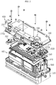
- FIG. 1 is an assembled perspective view schematically showing a structure of a secondary battery pack according to an embodiment
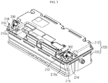
- FIG. 2 is a partially exploded perspective view of FIG. 1
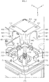
- FIG. 3 is a diagram showing a state in which a terminal cover is removed from a state of FIG. 1 .
- a secondary battery pack 10 includes a cell assembly 100, a pack case 200, an electrode terminal 300, and a terminal cover 400.
- the cell assembly 100 includes one or more secondary batteries.
- the cell assembly 100 may be an assembly including a plurality of secondary batteries.
- the plurality of secondary batteries may be pouch type secondary batteries.
- the pouch type secondary batteries may be configured to be stacked in a direction, e.g., in an up-and-down direction.
- the cell assembly 100 may further include a stacking frame 110.
- the stacking frame 110 is an element used to stack the secondary batteries, and holds the secondary batteries to prevent the secondary batteries from moving and is configured to be stackable to guide assembling of the secondary batteries.
- the stacking frame 110 may be expressed in other various terms such as a cartridge, etc., and may be configured as a square ring having empty center portion. In this case, four corners of the stacking frame 110 may be respectively located at an outer circumference of the pouch type secondary battery.
- the secondary battery pack 10 may further include a sensing unit 500 and electrical equipment 600.
- the sensing unit 500 transmits sensing information about electric characteristics such as a voltage of the secondary battery to a device such as BMS.
- the BMS may control the secondary batteries based on voltage information transmitted from the sensing unit 500.
- the sensing unit 500 may be mounted on the stacking frames 110 as shown in FIG. 2 , so as to be electrically connected to electrode leads of the plurality of secondary batteries.
- the electrical equipment 600 may include at least one of a BMS, a current sensor, a relay, and a fuse.
- the BMS battery management system
- the BMS is an element generally included in the secondary battery pack 10.
- a current sensor is an element for sensing charging/discharging currents of the secondary battery pack 10
- a relay is a switching component for selectively opening/closing charging/discharging current paths through which charging/discharging currents of the secondary battery pack 10 flow.
- a fuse is provided on the charging/discharging paths of the secondary battery pack 10 and blocks flow of the charging/discharging currents when an abnormal situation occurs in the secondary battery pack 10.
- the current sensor, the relay, and the fuse may exchange information with the BMS, and may be controlled by the BMS.
- the above electrical equipment 600 may be arranged on an upper portion of the stacking frames 110.
- the pack case 200 includes an internal space that is empty therein to accommodate the cell assembly 100, the sensing unit 500, and the electrical equipment 600 in the internal space.
- the pack case 200 may function as an exterior material of the secondary battery pack 10, and thus, the pack case 200 provides structural stability to the secondary battery pack 10 and protects the components such as the cell assembly 100 accommodated therein against external physical elements such as shock, impurities, etc.
- the pack case 200 may include a lower case 220 and an upper case 210, as shown in FIGS. 1 to 3 .
- the lower case 220 may have an open upper portion and an accommodation space therein, and the upper case 210 may be configured to cover the open upper portion of the lower case 220.
- the lower case 220 and the upper case 210 may be coupled to each other when boundaries thereof are coupled to each other via a coupling member such as a bolt.
- the pack case 200 has a square-shaped upper surface, two of four corners of which include terminal cover mounting parts 210a that are depressed from the upper surface of the pack case 200.
- the terminal cover mounting parts 210a are provided at the outermost corners on an upper surface of the upper case 210, and thus, the terminal cover mounting part 210a may have open outer surfaces and inner side surfaces surrounded by wall surfaces having a predetermined height.
- the terminal cover mounting part 210a includes a through hole 211 formed in a longitudinal direction.
- the pack case of the present embodiment may be configured so that the electrode terminal 300 may expose to an outer part of the upper case 210 via the through hole 211 of the terminal cover mounting part 210a when the upper case 210 and the lower case 220 are coupled to each other.
- the electrode terminal 300 is connected to the cell assembly 100 to provide a terminal that allows the cell assembly 100 to be electrically connected to an external device.
- the electrode terminal 300 may be directly or indirectly connected to electrode leads of the secondary batteries included in the cell assembly 100.
- the electrode terminal 300 may be electrically connected to the electrode lead of the secondary battery via a bus bar.
- the electrode terminal 300 may be exposed to the outer part of the pack case 200 as described above, in a state of connecting to the cell assembly 100.
- Two electrode terminals 300 may be included in the secondary battery pack 10.
- one electrode terminal 300 may function as a positive electrode terminal and the other electrode terminal 300 may function as a negative electrode terminal.
- the electrode terminal 300 may include a positive electrode terminal and a negative electrode terminal, and in this case, the positive electrode terminal is connected to a positive electrode lead of the secondary battery included in the cell assembly 100 and the negative electrode terminal may be connected to a negative electrode lead of the secondary battery.
- the electrode terminal 300 may protrude as shown in the drawing.
- a connecting operation may be easily performed and a connecting structure may be simplified.
- a connecting structure may be simplified.
- the electrode terminal 300 protrudes upward as in the above embodiment, an operator may easily perform a connecting operation of a cable to the electrode terminal 300 from the upper portion of the secondary battery pack 10.
- the terminal cover 400 is attachable to and detachable from the terminal cover mounting parts 210a to cover an upper portion and a part of a side surface of the electrode terminal 300. That is, the electrode terminal 300 may protrude to the outer part of the pack case 200, and in this case, the terminal cover 400 may cover the electrode terminal 300 except for a part, so that only a part may be exposed outside and remaining part may not be exposed.
- an opening part of the terminal cover 400 may be used as a passage of a cable (not shown) connected to the electrode terminal 300.
- the exposure of the electrode terminal 300 to the outside may be reduced.
- problems caused by the exposure of the electrode terminal 300 e.g., contacting of a metal material to the electrode terminal 300 and occurrence of an internal short-circuit, spark, a fire, etc., may be effectively prevented.
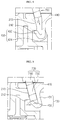
- FIG. 4 is a partially enlarged perspective view of a part A of FIG. 1
- FIG. 5 is a perspective view showing a state in which the terminal cover 400 is separated in FIG. 4
- FIG. 6 is a top view of FIG. 4
- FIG. 7 is a cross-sectional view taken along a line I-I' of FIG. 6 .
- the terminal cover 400 includes an upper plate 410 covering an upper part of the electrode terminal 300 and side plates 420 partially covering side surfaces of the electrode terminal 300.
- the electrode terminal 300 may be shielded except for a front side surface and a right side surface thereof in the drawings.
- the front side surface denotes a side surface right in front of the electrode terminal 300 and the right side surface is a side surface at right of the electrode terminal 300 when the secondary battery pack 10 is seen in a direction of an arrow B as shown in FIG. 1 .
- a rear side surface and a left side surface of the electrode terminal 300 may be blocked by wall surfaces of the terminal cover mounting part 210a.
- Each side plate 420 of the terminal cover 400 includes a cut portion 421 that is partially cut.
- two cut portions 421 are provided in the terminal cover 400 in different directions.
- One of the two cut portions 421 may be used as a passage for the cable wiring, and at this time, the operator may select one of the cut portions 421, which is suitable for the operation of wiring the cable.
- a location of another secondary battery pack 10 or an external device that has to be electrically connected to the secondary battery pack 10 in the drawings may be relatively changed, and thus an accessing direction or an extending direction of the cable for the electric connection between them may also vary.
- the terminal cover 400 includes the cut portions 421 respectively in the front side surface and the right side surface of the electrode terminal 300 in order to effectively deal with the variation in the cable connecting structure.
- the upper plate 410 of the terminal cover 400 is formed as a square corresponding to an upper area of the terminal cover mounting part 210a, and the side plates 420 correspond to two outer surfaces and have a height corresponding to that of the wall surface.
- the terminal cover 400 may be attached to/detached from the terminal cover mounting part 210a in a longitudinal direction.
- the terminal cover mounting part 210a and the terminal cover 400 respectively include a stopper 212 and a hooking protrusion 430 that are configured to hook-coupled to each other.
- the stopper 212 may be provided by partially depressing inward the wall surface of the terminal cover mounting part 210a, as shown in FIG. 5 .
- an inclined surface 213 is formed right on the stopper 212, and the inclined surface 213 guides the hooking protrusion 430 downward to be hook-coupled by the stopper 212 when the terminal cover 400 is attached.
- the hooking protrusion 430 is located at an inner space of the side plates 420 of the terminal cover 400 to extend downward from the upper plate 410 of the terminal cover 400, and may be configured to be hooked by the stopper 212 from upper and lower portions of each other.
- the hooking protrusion 430 may include a supporter 431 spaced a predetermined distance d from the stopper 212 in a transverse direction and extending vertically downward from the upper plate 410 of the terminal cover 400, and a coupling portion 432 curved upward from an end of the supporter 431 in a direction towards the hooking protrusion 212 to contact the stopper 212.
- the hooking protrusion 430 is formed on the upper plate 410 of the terminal cover 400 as a cantilever, and the supporter 431 is elastic to be curved within a predetermined range by an external force.
- Two stoppers 212 and two hooking protrusions 430 may be respectively provided on the terminal cover mounting part 210a and the terminal cover 400, and directions in which the two stoppers 430 are hook-coupled by the corresponding hooking protrusions 212 are different from each other.
- two stoppers 212 may be respectively formed on two crossing wall surfaces of the terminal cover mounting part 210a, and one of the two hooking protrusions 430 corresponding to the stoppers 212 is coupled to one stopper 212 in an X-axis direction of FIG. 4 and the other hooking protrusion 430 is coupled to the other stopper 212 in a Y-axis direction of FIG. 4 .
- the hook-coupled states in the X-axis and Y-axis directions have to be unhooked at the same time to separate the terminal cover 400. That is, the terminal cover 400 may be stably fixed to the upper case 210 to protect the electrode terminal 300.
- the present disclosure is not limited to the example, in which one stopper 212 is provided on one side wall of the terminal cover mounting part 210a and one hooking protrusion 430 corresponds to the stopper 212. That is, one or more pairs of stoppers 212 and hooking protrusions 430 may be respectively coupled to each other in different directions.
- the terminal cover mounting part 210a includes at least one of a protrusion and a groove
- the terminal cover 400 includes at least one of a groove and a protrusion corresponding to those of the terminal cover mounting parts 210a.
- the terminal cover mounting part 210a may further include first protrusions P1 protruding from the external surface thereof, and second grooves H1 formed as concavo-convex structures along upper boundaries of the wall surfaces.
- first grooves H2 engaged with the first protrusions and second protrusions engaged with the second grooves may be respectively provided in lower ends of the side plates 420 and opposite side surfaces of the terminal cover 400, which are not seen in the drawings.
- the terminal cover 400 may be held by the upper case 210 and may be restricted to move back and forth, and to left and right.
- the terminal cover 400 further includes a concave portion 440 at a corner where the side plates 420 cross each other.
- the concave portion 440 has a structure of being depressed or curved towards the inner portion of the terminal cover 400 between the two side plates 420.
- the terminal cover mounting part 210a includes an internal column 214 that is located in an internal area of the terminal cover 400 based on the concave portion 440 to support the upper plate 410 of the terminal cover 400, and an external column 215 provided to be inserted to the concave portion 440 in a longitudinal direction at an outer part of the terminal cover 400.
- the internal column 214 supports the upper plate 410 of the terminal cover 400 at the internal area of the terminal cover 400 to provide the terminal cover 400 with mechanical supporting force
- the external column 215 guides the mounting operation of the terminal cover 400 in the longitudinal direction and supports the terminal cover 400 at the outer part by being inserted into the internal space of the concave portion 440 to prevent the terminal cover 400 from moving in the transverse direction as shown in FIG. 6 .
- the terminal cover 400 may further include a jig hole 411 in the upper plate 410 of the terminal cover 400.
- the jig hole 411 is a hole provided to guide insertion of a cover separating jig 700 from the outer part of the terminal cover 400 into the terminal cover 400.
- the cover separating jig 700 (see FIG. 9 ) may be a bar-shaped tool for releasing the hooking protrusion 430 that has been hook-coupled in the internal area of the terminal cover 400 from the stopper 212.
- the hooking protrusion 430 may be separated from the stopper 212 when it is pushed by the cover separating jig 700 that is inserted through the jig hole 411, and the engagement in the longitudinal direction may be released. That is, two jig holes 411 are formed in the upper plate 410 of the terminal cover 400, and the cover separating jig 700 is inserted into each of the jig holes 411 to release the hook-coupling state of the hooking protrusion 430 from the stopper 212 and then the terminal cover 400 is lifted to be detached from the upper case 210.
- FIGS. 8 and 9 are partially enlarged views showing the terminal cover 400 before and after inserting the cover separating jig 700.
- the jig hole 411 may be located above a coupling portion 432.
- the cover separating jig 700 may be introduced to the internal space of the terminal cover 400, that is, a space between the stopper 212 and the supporter 431 of the hooking protrusion 430, through the jig hole 411.
- the jig hole 411 may be formed in the upper plate 410 of the terminal cover 400 to be inclined by a predetermined angle ( ⁇ ) with respect to a vertical direction.
- the upper plate 410 of the terminal cover 400 has a predetermined thickness, and the upper plate 410 is perforated in an inclined state by a predetermined angle to form the jig hole 411.
- the inclined direction of the jig hole 411 may face the supporter 431 of the hooking protrusion 430.
- the cover separating jig 700 may be inserted in a direction C to be inclined by a predetermined angle with respect to the upper plate 410, and the hooking protrusion 430 is elastically curved in a direction D and released from the stopper 212 when the cover separating jig 700 pushes the hooking protrusion 430.
- the cover separating jig 700 may include a compressor 720 that may pass through the jig hole 411 and a head 710 that may not be inserted to the jig hole 411. That is, the compressor 720 is integrally formed with the head 710, and has a smaller cross-sectional area than the head 710. In addition, the jig hole 411 may have a diameter that only allows the compressor 720 to be inserted therein.
- a length of the compressor 720 may be determined to correspond to an elastic deformation value of the hooking protrusion 430, which makes the hooking protrusion 430 separated from the stopper 212. By restricting the length and the insertion depth of the compressor 720, an excessive power may not be applied to the hooking protrusion 430, and thereby damage on the components may be prevented.
- the pack case 200 and the terminal cover 400 may be easily attached to/detached from each other and a coupling force therebetween may be improved comparing with the related art, and thus, safety of the secondary battery pack 10 may be improved.
- the coupling state between the hooking protrusion 430 of the terminal cover 400 and the stopper 212 of the terminal cover mounting part 210a is to be released, and accordingly, a power having an accurate and appropriate strength may be applied to the coupling portion. Therefore, anyone may separate the terminal cover 400 from the pack case 200 without concerning about the breakdown of the components.
- a vehicle according to the present disclosure may include the secondary battery pack 10 according to the present disclosure.
- the secondary battery pack 10 may be applied to a vehicle such as an electric vehicle or a hybrid car, and moreover, may be also applied to information technology (IT) products.
- IT information technology
Description
- The present disclosure relates to a secondary battery pack including a plurality of secondary batteries, and more particularly, to a secondary battery pack configured to cover an electrode terminal to reduce exposure to the outside and also to allow a connection member to be connected to the electrode terminal.
- The present application claims priority to Korean Patent Application No.
10-2015-0181751 filed on December 18, 2015 - Recently, secondary batteries have been widely used in a medium and/or large-scale device such as a vehicle and a power storage device, as well as a small device such as a portable electronic device. In particular, since carbon-based energy is gradually depleted and concern about environment has been increasing, hybrid cars and electric vehicles are being highlighted worldwide including USA, Europe, Japan, and Korea.
- In hybrid cars or electric vehicles, the most important component is a secondary battery pack providing a motor of a vehicle with a driving power. Since a driving power of a hybrid car or an electric vehicle is obtained through charging/discharging of a secondary battery pack, the hybrid car or the electric vehicle has various advantages in various aspects, for example, excellent mileage, no discharge or reduced discharge of pollution materials, etc., and thus, people using the hybrid car or the electric vehicle have been increasing.
- A secondary battery pack of a hybrid car or an electric vehicle includes a plurality of secondary batteries, and the plurality of secondary batteries are connected to one another in series or in parallel to improve capacity and output. A general secondary battery pack including the above secondary battery pack for a vehicle includes a cell assembly in which a plurality of secondary batteries are stacked and a pack case accommodating the cell assembly therein. Also, in order to use such a secondary battery pack, the secondary battery pack has to be electrically connected to an external device via a connection member such as a connecting wire or a bus bar, and to do this, the secondary battery pack may include an electrode terminal. In particular, the electrode terminal is likely to protrude from the pack case to an outer part and be exposed in order to be easily coupled to the connection member. Therefore, an end of the connection member is coupled in contact with the electrode terminal and the other end is connected to an external device, e.g., a motor, in a state of extending from the end via an electric wire, and thus, a driving power may be supplied from a battery pack to the motor.
- However, there are some problems when an electrode terminal of a secondary battery pack is exposed to an outer part of a pack case. For example, a conductive material such as a bolt, a piece of metal, or an electric wire may contact the electrode terminal, and in this case, an external short-circuit may occur. In addition, the contact of the conductive material may cause damage on the battery pack or an electric system, and moreover, may generate spark that results in fire. Therefore, to address the above problems, there have been attempts to reduce or remove the exposure of the electrode terminal, and a configuration of connecting a connecting wire to the electrode terminal and then covering an outer part of the electrode terminal with a terminal cover is a representative method.
- Such a terminal cover is detachably mounted on a pack case in order to perform a rewiring of the electrode terminal and the connecting wire and maintenance while protecting the electrode terminal. As an example, the terminal cover may have a restrictively exposed side surface so as to allow a connecting wire to access, and may be configured to be mounted on an upper surface of the pack case in a bolting manner or a hook manner.
- However, according to the bolting manner that is applied to mounting of the terminal cover according to the related art, although a coupling force may be excellent, a bolt has to be fastened and loosened repeatedly and the bolt is likely to contact the electrode terminal during disassembling and assembling processes. On the other hand, according to the hook manner, an assembling process may be simpler and safer than the bolting manner, but a coupling force is weak and an excessive power that may be applied in the disassembling and assembling processes may unintentionally break components. An example of a battery pack can be found in the European patent application No.
3093908 . Patent document No.KR101003962 - The present disclosure is designed to solve the problems of the related art, and therefore the present disclosure is directed to providing a secondary battery pack capable of minimizing an exposure of an electrode terminal to ensure safety and implementing a robust coupling of a terminal cover while enabling easy attachment and detachment of the terminal cover.
- The other objects and advantages of the present disclosure will be apparent from the following description and the exemplary embodiments of the present disclosure. Also, it will be readily understood that the objects and advantages of the present disclosure are realized by the means and combinations thereof set forth in the appended claims.
- A secondary battery pack according to the present invention is defined by claim 1. Dependent claims relate to preferred embodiments. The secondary battery pack including: a cell assembly including a plurality of secondary batteries; a pack case having an internal space for accommodating the cell assembly; an electrode terminal connected to the cell assembly and protruding to the outside of the pack case; and a terminal cover configured to cover an upper portion and partial side surfaces of the electrode terminal, and to be detachable from the pack case by including a hooking protrusion that is hook-coupled to and released from a stopper that is provided in the pack case.
- In particular, the terminal cover further includes a jig hole configured to allow a cover separating jig to be inserted from outside to inside, and the hooking protrusion is provided at an internal area of the terminal cover to be released from the stopper when the cover separating jig inserted through the jig hole pushes the hooking protrusion.
- The pack case includes a terminal cover mounting part having a square-shaped upper surface and four corners, at least one of which is depressed, the electrode terminal is located on the terminal cover mounting part, and the terminal cover is coupled to the terminal cover mounting part.
- The terminal cover mounting part includes a through hole provided in a vertical direction so that the electrode terminal protrudes to the outside, and the terminal cover includes an upper plate covering an upper portion of the electrode terminal, and side plates partially covering side surfaces of the electrode terminal.
- The hooking protrusion may extend downward from the upper plate of the terminal cover, and the stopper may be partially depressed inward from a wall surface of the terminal cover mounting part.
- The stopper comprises two stoppers, respectively on two crossing wall surfaces of the terminal cover mounting part, and the hooking protrusion comprises two hooking protrusions corresponding to the two stoppers and the two hooking protrusions may be hook-coupled to the two stoppers in different directions.
- The hooking protrusion and the stopper may be configured to be vertically hook-coupled to each other.
- An inclined surface that guides the hooking protrusion downward to be hook-coupled to the stopper may be formed on an upper part of the stopper.
- The hooking protrusion may include: a supporter spaced a predetermined distance from the stopper in a transverse direction and extending perpendicularly downward from the upper plate of the terminal cover; and a coupling portion curved upward from an end of the supporter in a direction towards the stopper to contact the stopper, and the jig hole may be located above the coupling portion.
- The jig hole may be formed in the upper plate to be inclined by a predetermined angle with respect to a vertical direction.
- The terminal cover mounting part may include at least one of a protrusion and a groove, and the terminal cover may include at least one of a groove and a protrusion corresponding to the terminal cover mounting part.
- The terminal cover includes a concave portion formed by depressing a corner where the two side plates cross each other into an internal area of the terminal cover, and the terminal cover mounting part includes an internal column located at an internal area of the terminal cover based on the concave portion to support the upper plate of the terminal cover, and an external column provided to be inserted in the concave portion in a longitudinal direction from an outer part of the terminal cover.
- The electrode terminal may include a positive electrode terminal and a negative electrode terminal, and the terminal cover comprises two terminal covers respectively covering the positive electrode terminal and the negative electrode terminal.
- The cover separating jig may include a head and a compressor extending from the head and having a smaller cross-sectional area than the head, and the jig hole may be equal to or greater than a cross-sectional area of the compressor and smaller than a cross-sectional area of the head.
- In another aspect of the present disclosure, there is also provided a vehicle including the above-described secondary battery pack.
- According to an aspect of the present disclosure, a pack case and a terminal cover may be easily attached to and detached from each other when comparing with the related art, and also a coupling force may be relatively improved, and thus safety of a secondary battery pack may be improved.
- In particular, when the terminal cover is separated from the pack case, the terminal cover may be configured to be separated from the pack case when an additional cover separating jig is pushed into a jig hole to a predetermined depth, and thus, anyone may accurately apply a power of an appropriate degree to a hook coupling part and the terminal cover may be safely separated from the pack case without breaking components.
-
-
FIG. 1 is an assembled perspective view schematically showing a configuration of a secondary battery pack according to an embodiment of the present disclosure. -
FIG. 2 is a partially exploded perspective view ofFIG. 1 . -
FIG. 3 is a diagram showing a state in which a terminal cover is removed inFIG. 1 . -
FIG. 4 is an enlarged perspective view of a part A ofFIG. 1 . -
FIG. 5 is a diagram showing a state in which a terminal cover is separated inFIG. 4 . -
FIG. 6 is a top view ofFIG. 4 . -
FIG. 7 is a cross-sectional view taken along a line I-I' ofFIG. 6 . -
FIGS. 8 and 9 are partially enlarged views showing states before and after inserting a cover separating jig. - Hereinafter, preferred embodiments of the present disclosure will be described in detail with reference to the accompanying drawings. Prior to the description, it should be understood that the terms used in the specification and the appended claims should not be construed as limited to general and dictionary meanings, but interpreted based on the meanings and concepts corresponding to technical aspects of the present disclosure on the basis of the principle that the inventor is allowed to define terms appropriately for the best explanation.
- Therefore, the description proposed herein is just a preferable example for the purpose of illustrations only, not intended to limit the scope of the disclosure, so it should be understood that other equivalents and modifications could be made thereto without departing from the scope of the disclosure.
-
FIG. 1 is an assembled perspective view schematically showing a structure of a secondary battery pack according to an embodiment,FIG. 2 is a partially exploded perspective view ofFIG. 1 , andFIG. 3 is a diagram showing a state in which a terminal cover is removed from a state ofFIG. 1 . - Referring to
FIGS. 1 to 3 , asecondary battery pack 10 according to the present disclosure includes acell assembly 100, apack case 200, anelectrode terminal 300, and aterminal cover 400. - The
cell assembly 100 includes one or more secondary batteries. In particular, in thesecondary battery pack 10, thecell assembly 100 may be an assembly including a plurality of secondary batteries. Here, the plurality of secondary batteries may be pouch type secondary batteries. In this case, the pouch type secondary batteries may be configured to be stacked in a direction, e.g., in an up-and-down direction. - In addition, the
cell assembly 100 may further include a stackingframe 110. The stackingframe 110 is an element used to stack the secondary batteries, and holds the secondary batteries to prevent the secondary batteries from moving and is configured to be stackable to guide assembling of the secondary batteries. The stackingframe 110 may be expressed in other various terms such as a cartridge, etc., and may be configured as a square ring having empty center portion. In this case, four corners of the stackingframe 110 may be respectively located at an outer circumference of the pouch type secondary battery. - In the present embodiment, the
secondary battery pack 10 may further include asensing unit 500 andelectrical equipment 600. - The
sensing unit 500 transmits sensing information about electric characteristics such as a voltage of the secondary battery to a device such as BMS. The BMS may control the secondary batteries based on voltage information transmitted from thesensing unit 500. Thesensing unit 500 may be mounted on the stackingframes 110 as shown inFIG. 2 , so as to be electrically connected to electrode leads of the plurality of secondary batteries. - The
electrical equipment 600 may include at least one of a BMS, a current sensor, a relay, and a fuse. Here, the BMS (battery management system) is a secondary battery management device that controls overall charging/discharging operations of thesecondary battery pack 10. The BMS is an element generally included in thesecondary battery pack 10. Also, a current sensor is an element for sensing charging/discharging currents of thesecondary battery pack 10, and a relay is a switching component for selectively opening/closing charging/discharging current paths through which charging/discharging currents of thesecondary battery pack 10 flow. A fuse is provided on the charging/discharging paths of thesecondary battery pack 10 and blocks flow of the charging/discharging currents when an abnormal situation occurs in thesecondary battery pack 10. The current sensor, the relay, and the fuse may exchange information with the BMS, and may be controlled by the BMS. The aboveelectrical equipment 600 may be arranged on an upper portion of the stacking frames 110. - The
pack case 200 includes an internal space that is empty therein to accommodate thecell assembly 100, thesensing unit 500, and theelectrical equipment 600 in the internal space. Thepack case 200 may function as an exterior material of thesecondary battery pack 10, and thus, thepack case 200 provides structural stability to thesecondary battery pack 10 and protects the components such as thecell assembly 100 accommodated therein against external physical elements such as shock, impurities, etc. - In addition, the
pack case 200 may include alower case 220 and anupper case 210, as shown inFIGS. 1 to 3 . Here, thelower case 220 may have an open upper portion and an accommodation space therein, and theupper case 210 may be configured to cover the open upper portion of thelower case 220. In addition, thelower case 220 and theupper case 210 may be coupled to each other when boundaries thereof are coupled to each other via a coupling member such as a bolt. - In the present embodiment, the
pack case 200 has a square-shaped upper surface, two of four corners of which include terminalcover mounting parts 210a that are depressed from the upper surface of thepack case 200. - As shown in
FIGS. 2 and3 , the terminalcover mounting parts 210a are provided at the outermost corners on an upper surface of theupper case 210, and thus, the terminalcover mounting part 210a may have open outer surfaces and inner side surfaces surrounded by wall surfaces having a predetermined height. - In addition, the terminal
cover mounting part 210a includes a throughhole 211 formed in a longitudinal direction. The pack case of the present embodiment may be configured so that theelectrode terminal 300 may expose to an outer part of theupper case 210 via the throughhole 211 of the terminalcover mounting part 210a when theupper case 210 and thelower case 220 are coupled to each other. - The
electrode terminal 300 is connected to thecell assembly 100 to provide a terminal that allows thecell assembly 100 to be electrically connected to an external device. In more detail, theelectrode terminal 300 may be directly or indirectly connected to electrode leads of the secondary batteries included in thecell assembly 100. For example, theelectrode terminal 300 may be electrically connected to the electrode lead of the secondary battery via a bus bar. - Also, the
electrode terminal 300 may be exposed to the outer part of thepack case 200 as described above, in a state of connecting to thecell assembly 100. Twoelectrode terminals 300 may be included in thesecondary battery pack 10. Here, oneelectrode terminal 300 may function as a positive electrode terminal and theother electrode terminal 300 may function as a negative electrode terminal. That is, theelectrode terminal 300 may include a positive electrode terminal and a negative electrode terminal, and in this case, the positive electrode terminal is connected to a positive electrode lead of the secondary battery included in thecell assembly 100 and the negative electrode terminal may be connected to a negative electrode lead of the secondary battery. Preferably, theelectrode terminal 300 may protrude as shown in the drawing. - According to the configuration of the present disclosure, when a bus bar or a cable is connected to the
electrode terminal 300 of thesecondary battery pack 10, a connecting operation may be easily performed and a connecting structure may be simplified. For example, in a case where thesecondary battery pack 10 is mounted in an electric vehicle, when thesecondary battery pack 10 is to be repaired or replaced, access to thesecondary battery pack 10 may be made downward from an upper portion of thesecondary battery pack 10. Here, according to the configuration in which theelectrode terminal 300 protrudes upward as in the above embodiment, an operator may easily perform a connecting operation of a cable to theelectrode terminal 300 from the upper portion of thesecondary battery pack 10. - The
terminal cover 400 is attachable to and detachable from the terminalcover mounting parts 210a to cover an upper portion and a part of a side surface of theelectrode terminal 300. That is, theelectrode terminal 300 may protrude to the outer part of thepack case 200, and in this case, theterminal cover 400 may cover theelectrode terminal 300 except for a part, so that only a part may be exposed outside and remaining part may not be exposed. In addition, an opening part of theterminal cover 400 may be used as a passage of a cable (not shown) connected to theelectrode terminal 300. - According to the structure of the
terminal cover 400, the exposure of theelectrode terminal 300 to the outside may be reduced. Thus, problems caused by the exposure of theelectrode terminal 300, e.g., contacting of a metal material to theelectrode terminal 300 and occurrence of an internal short-circuit, spark, a fire, etc., may be effectively prevented. -
FIG. 4 is a partially enlarged perspective view of a part A ofFIG. 1 ,FIG. 5 is a perspective view showing a state in which theterminal cover 400 is separated inFIG. 4 ,FIG. 6 is a top view ofFIG. 4 , andFIG. 7 is a cross-sectional view taken along a line I-I' ofFIG. 6 . - Referring to
FIGS. 4 to 7 , the configuration of theterminal cover 400 will be described in more detail, that is, theterminal cover 400 includes anupper plate 410 covering an upper part of theelectrode terminal 300 andside plates 420 partially covering side surfaces of theelectrode terminal 300. When theterminal cover 400 is coupled to the terminalcover mounting parts 210 of theupper case 210, theelectrode terminal 300 may be shielded except for a front side surface and a right side surface thereof in the drawings. Here, the front side surface denotes a side surface right in front of theelectrode terminal 300 and the right side surface is a side surface at right of theelectrode terminal 300 when thesecondary battery pack 10 is seen in a direction of an arrow B as shown inFIG. 1 . A rear side surface and a left side surface of theelectrode terminal 300 may be blocked by wall surfaces of the terminalcover mounting part 210a. - Each
side plate 420 of theterminal cover 400 includes acut portion 421 that is partially cut. In particular, as shown inFIG. 4 , two cutportions 421 are provided in theterminal cover 400 in different directions. One of the two cutportions 421 may be used as a passage for the cable wiring, and at this time, the operator may select one of thecut portions 421, which is suitable for the operation of wiring the cable. For example, a location of anothersecondary battery pack 10 or an external device that has to be electrically connected to thesecondary battery pack 10 in the drawings may be relatively changed, and thus an accessing direction or an extending direction of the cable for the electric connection between them may also vary. As an example, theterminal cover 400 includes thecut portions 421 respectively in the front side surface and the right side surface of theelectrode terminal 300 in order to effectively deal with the variation in the cable connecting structure. - In the present embodiment, the
upper plate 410 of theterminal cover 400 is formed as a square corresponding to an upper area of the terminalcover mounting part 210a, and theside plates 420 correspond to two outer surfaces and have a height corresponding to that of the wall surface. Theterminal cover 400 may be attached to/detached from the terminalcover mounting part 210a in a longitudinal direction. - Hereinafter, attaching and detaching structure between the
terminal cover 400 and theupper case 210 will be described in more detail below with reference toFIGS. 4 to 7 . - The terminal
cover mounting part 210a and theterminal cover 400 respectively include astopper 212 and a hookingprotrusion 430 that are configured to hook-coupled to each other. Thestopper 212 may be provided by partially depressing inward the wall surface of the terminalcover mounting part 210a, as shown inFIG. 5 . In addition, aninclined surface 213 is formed right on thestopper 212, and theinclined surface 213 guides the hookingprotrusion 430 downward to be hook-coupled by thestopper 212 when theterminal cover 400 is attached. - The hooking
protrusion 430 is located at an inner space of theside plates 420 of theterminal cover 400 to extend downward from theupper plate 410 of theterminal cover 400, and may be configured to be hooked by thestopper 212 from upper and lower portions of each other. - As shown in
FIG. 7 , the hookingprotrusion 430 may include asupporter 431 spaced a predetermined distance d from thestopper 212 in a transverse direction and extending vertically downward from theupper plate 410 of theterminal cover 400, and acoupling portion 432 curved upward from an end of thesupporter 431 in a direction towards the hookingprotrusion 212 to contact thestopper 212. The hookingprotrusion 430 is formed on theupper plate 410 of theterminal cover 400 as a cantilever, and thesupporter 431 is elastic to be curved within a predetermined range by an external force. - Two
stoppers 212 and two hookingprotrusions 430 may be respectively provided on the terminalcover mounting part 210a and theterminal cover 400, and directions in which the twostoppers 430 are hook-coupled by the corresponding hookingprotrusions 212 are different from each other. For example, twostoppers 212 may be respectively formed on two crossing wall surfaces of the terminalcover mounting part 210a, and one of the two hookingprotrusions 430 corresponding to thestoppers 212 is coupled to onestopper 212 in an X-axis direction ofFIG. 4 and the other hookingprotrusion 430 is coupled to theother stopper 212 in a Y-axis direction ofFIG. 4 . Therefore, the hook-coupled states in the X-axis and Y-axis directions have to be unhooked at the same time to separate theterminal cover 400. That is, theterminal cover 400 may be stably fixed to theupper case 210 to protect theelectrode terminal 300. - In addition, the present disclosure is not limited to the example, in which one
stopper 212 is provided on one side wall of the terminalcover mounting part 210a and one hookingprotrusion 430 corresponds to thestopper 212. That is, one or more pairs ofstoppers 212 and hookingprotrusions 430 may be respectively coupled to each other in different directions. - In the present embodiment, the terminal
cover mounting part 210a includes at least one of a protrusion and a groove, and theterminal cover 400 includes at least one of a groove and a protrusion corresponding to those of the terminalcover mounting parts 210a. - For example, as shown in
FIGS. 4 and5 , the terminalcover mounting part 210a may further include first protrusions P1 protruding from the external surface thereof, and second grooves H1 formed as concavo-convex structures along upper boundaries of the wall surfaces. In addition, first grooves H2 engaged with the first protrusions and second protrusions engaged with the second grooves may be respectively provided in lower ends of theside plates 420 and opposite side surfaces of theterminal cover 400, which are not seen in the drawings. - Through the engagement or concavo-convex coupling structure between the protrusions and the grooves of the terminal
cover mounting part 210a and theterminal cover 400, theterminal cover 400 may be held by theupper case 210 and may be restricted to move back and forth, and to left and right. - Also, the
terminal cover 400 further includes aconcave portion 440 at a corner where theside plates 420 cross each other. Here, theconcave portion 440 has a structure of being depressed or curved towards the inner portion of theterminal cover 400 between the twoside plates 420. - In addition, the terminal
cover mounting part 210a includes aninternal column 214 that is located in an internal area of theterminal cover 400 based on theconcave portion 440 to support theupper plate 410 of theterminal cover 400, and anexternal column 215 provided to be inserted to theconcave portion 440 in a longitudinal direction at an outer part of theterminal cover 400. - The
internal column 214 supports theupper plate 410 of theterminal cover 400 at the internal area of theterminal cover 400 to provide theterminal cover 400 with mechanical supporting force, and theexternal column 215 guides the mounting operation of theterminal cover 400 in the longitudinal direction and supports theterminal cover 400 at the outer part by being inserted into the internal space of theconcave portion 440 to prevent theterminal cover 400 from moving in the transverse direction as shown inFIG. 6 . - Also, the
terminal cover 400 may further include ajig hole 411 in theupper plate 410 of theterminal cover 400. Thejig hole 411 is a hole provided to guide insertion of acover separating jig 700 from the outer part of theterminal cover 400 into theterminal cover 400. Here, the cover separating jig 700 (seeFIG. 9 ) may be a bar-shaped tool for releasing the hookingprotrusion 430 that has been hook-coupled in the internal area of theterminal cover 400 from thestopper 212. - For example, the hooking
protrusion 430 may be separated from thestopper 212 when it is pushed by thecover separating jig 700 that is inserted through thejig hole 411, and the engagement in the longitudinal direction may be released. That is, twojig holes 411 are formed in theupper plate 410 of theterminal cover 400, and thecover separating jig 700 is inserted into each of the jig holes 411 to release the hook-coupling state of the hookingprotrusion 430 from thestopper 212 and then theterminal cover 400 is lifted to be detached from theupper case 210. -
FIGS. 8 and 9 are partially enlarged views showing theterminal cover 400 before and after inserting thecover separating jig 700. - Referring to
FIGS. 7 to 9 , thejig hole 411 may be located above acoupling portion 432. Thecover separating jig 700 may be introduced to the internal space of theterminal cover 400, that is, a space between thestopper 212 and thesupporter 431 of the hookingprotrusion 430, through thejig hole 411. - In addition, as shown in
FIGS. 7 and8 , thejig hole 411 may be formed in theupper plate 410 of theterminal cover 400 to be inclined by a predetermined angle (θ) with respect to a vertical direction. For example, theupper plate 410 of theterminal cover 400 has a predetermined thickness, and theupper plate 410 is perforated in an inclined state by a predetermined angle to form thejig hole 411. Here, the inclined direction of thejig hole 411 may face thesupporter 431 of the hookingprotrusion 430. - According to the structure of the
jig hole 411, as shown inFIGS. 8 and 9 , thecover separating jig 700 may be inserted in a direction C to be inclined by a predetermined angle with respect to theupper plate 410, and the hookingprotrusion 430 is elastically curved in a direction D and released from thestopper 212 when thecover separating jig 700 pushes the hookingprotrusion 430. - The
cover separating jig 700 may include acompressor 720 that may pass through thejig hole 411 and ahead 710 that may not be inserted to thejig hole 411. That is, thecompressor 720 is integrally formed with thehead 710, and has a smaller cross-sectional area than thehead 710. In addition, thejig hole 411 may have a diameter that only allows thecompressor 720 to be inserted therein. - Also, a length of the
compressor 720 may be determined to correspond to an elastic deformation value of the hookingprotrusion 430, which makes the hookingprotrusion 430 separated from thestopper 212. By restricting the length and the insertion depth of thecompressor 720, an excessive power may not be applied to the hookingprotrusion 430, and thereby damage on the components may be prevented. - As described above, according to the configuration of the
terminal cover 400 according to the present disclosure, thepack case 200 and theterminal cover 400 may be easily attached to/detached from each other and a coupling force therebetween may be improved comparing with the related art, and thus, safety of thesecondary battery pack 10 may be improved. - In particular, when the operator pushes the
cover separating jig 700 into thejig hole 411 to a predetermined depth, the coupling state between the hookingprotrusion 430 of theterminal cover 400 and thestopper 212 of the terminalcover mounting part 210a is to be released, and accordingly, a power having an accurate and appropriate strength may be applied to the coupling portion. Therefore, anyone may separate theterminal cover 400 from thepack case 200 without concerning about the breakdown of the components. - In addition, a vehicle according to the present disclosure may include the
secondary battery pack 10 according to the present disclosure. Thesecondary battery pack 10 may be applied to a vehicle such as an electric vehicle or a hybrid car, and moreover, may be also applied to information technology (IT) products. - The present disclosure has been described in detail. However, it should be understood that the detailed description and specific examples, while indicating preferred embodiments of the disclosure, are given by way of illustration only.
- On the other hand, it is obvious to one of ordinary skill in the art that the terms used to indicate the direction as described herein, such as 'upper', 'lower', 'right' and 'left', are only for convenience of description, and may be differently expressed depending on a viewing position of a viewer or a location where an object is placed.
Claims (10)
- A secondary battery pack (10) comprising:a cell assembly (100) comprising a plurality of secondary batteries;a pack case (200) having an internal space for accommodating the cell assembly (100) and comprising a terminal cover mounting part (210a) having a square-shaped upper surface and four corners, at least one of which is depressed;an electrode terminal (300) connected to the cell assembly (100) and protruding to an outside of the pack case (200) and located on the terminal cover mounting part (210a) that comprising a through hole (211) provided in a vertical direction so that the electrode terminal (300) protrudes to the outside; anda terminal cover (400) configured to cover an upper portion and partial side surfaces of the electrode terminal (300), and to be detachable from the pack case (200) by including a hooking protrusion (430) that is hook-coupled to and released from a stopper (212) that is provided in the pack case (200), and coupled to the terminal cover mounting part (210a),wherein the terminal cover (400) further comprises a jig hole (411) configured to allow a cover separating jig (700) to be inserted from outside to inside, and the hooking protrusion (430) is provided at an internal area of the terminal cover (400) to be released from the stopper (212) when the cover separating jig (700) inserted through the jig hole (411) pushes the hooking protrusion (430) and an upper plate (410) covering an upper portion of the electrode terminal (300) and side plates (420) partially covering side surfaces of the electrode terminal (300), and whereinthe terminal cover (400) comprises a concave portion (440) formed by depressing a corner where the two side plates cross each other into an internal area of the terminal cover (400), andthe terminal cover mounting part (210a) comprises an internal column (214) located at an internal area of the terminal cover (400) based on the concave portion (440) to support the upper plate (410) of the terminal cover (400), and an external column (215) provided to be inserted in the concave portion (440) in a longitudinal direction from an outer part of the terminal cover (400).
- The secondary battery pack (10) of claim 1, wherein the hooking protrusion (430) extends downward from the upper plate (410) of the terminal cover (400), and the stopper (212) is partially depressed inward from a wall surface of the terminal cover mounting part (210a).
- The secondary battery pack (10) of claim 2, wherein the stopper (212) comprises two stoppers, respectively on two crossing wall surfaces of the terminal cover mounting part (210a), and the hooking protrusion (430) comprises two hooking protrusions corresponding to the two stoppers and the two hooking protrusions are hook-coupled to the two stoppers in different directions.
- The secondary battery pack (10) of claim 2, wherein the hooking protrusion (430) and the stopper (212) are configured to be vertically hook-coupled to each other.
- The secondary battery pack (10) of claim 2, wherein an inclined surface that guides the hooking protrusion (430) downward to be hook-coupled to the stopper (212) is formed on an upper part of the stopper (212).
- The secondary battery pack (10) of claim 2, wherein the hooking protrusion (430) comprises:a supporter (431) spaced a predetermined distance (d) from the stopper (212) in a transverse direction and extending perpendicularly downward from the upper plate (410) of the terminal cover (400); anda coupling portion (432) curved upward from an end of the supporter (431) in a direction towards the stopper (212) to contact the stopper (212), andthe jig hole (411) is located above the coupling portion (432).
- The secondary battery pack (10) of claim 1, wherein the terminal cover mounting part (210a) comprises at least one of a protrusion and a groove, and the terminal cover (400) comprises at least one of a groove and a protrusion corresponding to the terminal cover mounting part (210a).
- The secondary battery pack (10) of claim 1, wherein the electrode terminal (300) comprises a positive electrode terminal and a negative electrode terminal, and the terminal cover (400) comprises two terminal covers respectively covering the positive electrode terminal and the negative electrode terminal.
- The secondary battery pack (10) of claim 1, wherein the cover separating jig (700) comprises a head (710) and a compressor (720) extending from the head (710) and having a smaller cross-sectional area than the head (710), and the jig hole is equal to or greater than a cross-sectional area of the compressor and smaller than a cross-sectional area of the head.
- A vehicle comprising the secondary battery pack (10) according to any one of claim 1 to claim 9.
Priority Applications (1)
| Application Number | Priority Date | Filing Date | Title |
|---|---|---|---|
| PL16875910T PL3306702T3 (en) | 2015-12-18 | 2016-11-02 | Secondary battery pack |
Applications Claiming Priority (2)
| Application Number | Priority Date | Filing Date | Title |
|---|---|---|---|
| KR1020150181751A KR102065106B1 (en) | 2015-12-18 | 2015-12-18 | Secondary Battery Pack |
| PCT/KR2016/012527 WO2017104968A1 (en) | 2015-12-18 | 2016-11-02 | Secondary battery pack |
Publications (3)
| Publication Number | Publication Date |
|---|---|
| EP3306702A1 EP3306702A1 (en) | 2018-04-11 |
| EP3306702A4 EP3306702A4 (en) | 2018-06-06 |
| EP3306702B1 true EP3306702B1 (en) | 2020-06-17 |
Family
ID=59056866
Family Applications (1)
| Application Number | Title | Priority Date | Filing Date |
|---|---|---|---|
| EP16875910.8A Active EP3306702B1 (en) | 2015-12-18 | 2016-11-02 | Secondary battery pack |
Country Status (7)
| Country | Link |
|---|---|
| US (1) | US11374277B2 (en) |
| EP (1) | EP3306702B1 (en) |
| JP (1) | JP6619087B2 (en) |
| KR (1) | KR102065106B1 (en) |
| CN (1) | CN107851750B (en) |
| PL (1) | PL3306702T3 (en) |
| WO (1) | WO2017104968A1 (en) |
Families Citing this family (7)
| Publication number | Priority date | Publication date | Assignee | Title |
|---|---|---|---|---|
| WO2019061329A1 (en) | 2017-09-29 | 2019-04-04 | Robert Bosch Gmbh | Battery pack including cell restraint |
| KR102412941B1 (en) | 2018-01-19 | 2022-06-23 | 주식회사 엘지에너지솔루션 | Terminal cover and battery pack comprising the same |
| KR102394740B1 (en) * | 2018-08-09 | 2022-05-04 | 주식회사 엘지에너지솔루션 | Apparatus for charging and discharging secondary battery |
| DE102019109725B4 (en) * | 2019-04-12 | 2023-12-14 | Dr. Ing. H.C. F. Porsche Aktiengesellschaft | Battery module and system consisting of battery connectors and battery modules |
| KR102350763B1 (en) * | 2020-04-29 | 2022-01-13 | (주)에디슨테크 | Coupling Structure of Terminal Cover for Battery |
| KR20220043543A (en) * | 2020-09-29 | 2022-04-05 | 에스케이온 주식회사 | Terminal Protection Cover and Battery Module Including the Same |
| WO2022246289A2 (en) * | 2021-05-21 | 2022-11-24 | Cps Technology Holdings Llc | Battery connector and battery cover |
Family Cites Families (19)
| Publication number | Priority date | Publication date | Assignee | Title |
|---|---|---|---|---|
| DE4300567A1 (en) * | 1993-01-12 | 1994-07-14 | Hagen Batterie Ag | Accumulator with removable cover plate covering the poles |
| JPH10208719A (en) * | 1997-01-28 | 1998-08-07 | Smk Corp | Cover of battery housing part |
| JP2001068082A (en) * | 1999-08-25 | 2001-03-16 | Sousei Denshi:Kk | Lid of battery box |
| JP4794736B2 (en) | 2001-01-31 | 2011-10-19 | 古河電池株式会社 | Storage battery terminal structure |
| JP5197985B2 (en) * | 2007-04-05 | 2013-05-15 | 日置電機株式会社 | Portable instrument with battery |
| KR101003962B1 (en) * | 2010-03-15 | 2010-12-30 | 주식회사 대륙 | Molded case circuit breaker |
| KR200461334Y1 (en) * | 2010-08-10 | 2012-07-06 | 세방전지(주) | A protection cover of terminal for battery |
| JPWO2012066707A1 (en) * | 2010-11-16 | 2014-05-12 | Necカシオモバイルコミュニケーションズ株式会社 | Cover lock structure |
| JP5762228B2 (en) | 2011-09-13 | 2015-08-12 | 矢崎総業株式会社 | In-vehicle battery assembly terminal block |
| US8955209B2 (en) | 2011-10-24 | 2015-02-17 | Diamond Innovations, Inc. | Method of joining two components to ensure axial and angular alignment therebetween |
| KR102023916B1 (en) * | 2012-07-23 | 2019-09-23 | 에스케이이노베이션 주식회사 | Connecting apparatus for battery electrode and terminal |
| KR20140060633A (en) * | 2012-11-12 | 2014-05-21 | 주식회사 엘지화학 | Battery module having bus bar assembly and battery pack comprising the same |
| JP6086315B2 (en) * | 2013-03-19 | 2017-03-01 | 株式会社Gsユアサ | Power storage device |
| WO2014185566A1 (en) * | 2013-05-15 | 2014-11-20 | 주식회사 엘지화학 | Battery module assembly having novel structure |
| JP2014231132A (en) | 2013-05-30 | 2014-12-11 | 日立工機株式会社 | Electric apparatus, electric instrument, and battery pack |
| KR101689750B1 (en) * | 2014-01-21 | 2016-12-26 | 주식회사 엘지화학 | Battery pack |
| KR101808307B1 (en) * | 2014-05-28 | 2017-12-12 | 주식회사 엘지화학 | Terminal cover and battery module including the same |
| KR101881196B1 (en) * | 2015-06-16 | 2018-07-23 | 주식회사 엘지화학 | Battery Pack |
| JP6128197B2 (en) * | 2015-12-21 | 2017-05-17 | 株式会社Gsユアサ | Battery pack, single battery, and cap |
-
2015
- 2015-12-18 KR KR1020150181751A patent/KR102065106B1/en active IP Right Grant
-
2016
- 2016-11-02 US US15/735,324 patent/US11374277B2/en active Active
- 2016-11-02 WO PCT/KR2016/012527 patent/WO2017104968A1/en active Application Filing
- 2016-11-02 CN CN201680039918.4A patent/CN107851750B/en active Active
- 2016-11-02 EP EP16875910.8A patent/EP3306702B1/en active Active
- 2016-11-02 JP JP2018515996A patent/JP6619087B2/en active Active
- 2016-11-02 PL PL16875910T patent/PL3306702T3/en unknown
Non-Patent Citations (1)
| Title |
|---|
| None * |
Also Published As
| Publication number | Publication date |
|---|---|
| WO2017104968A1 (en) | 2017-06-22 |
| CN107851750A (en) | 2018-03-27 |
| EP3306702A4 (en) | 2018-06-06 |
| US11374277B2 (en) | 2022-06-28 |
| JP6619087B2 (en) | 2019-12-11 |
| EP3306702A1 (en) | 2018-04-11 |
| KR102065106B1 (en) | 2020-01-10 |
| JP2018530874A (en) | 2018-10-18 |
| CN107851750B (en) | 2020-11-03 |
| KR20170073170A (en) | 2017-06-28 |
| US20180175342A1 (en) | 2018-06-21 |
| PL3306702T3 (en) | 2021-03-08 |
Similar Documents
| Publication | Publication Date | Title |
|---|---|---|
| EP3306702B1 (en) | Secondary battery pack | |
| KR101127603B1 (en) | Bus bar holder and battery pack comprising the same | |
| EP3285314B1 (en) | Secondary battery pack | |
| CN111149236B (en) | Battery pack | |
| KR20160129597A (en) | Battery pack and method for manufacturing the same | |
| CN112004643B (en) | Bolting device for producing a battery pack and use thereof | |
| KR102441019B1 (en) | Battery module with short-circuit protection structure | |
| CN111149234A (en) | Electrically connected component housing case and battery module | |
| KR102269112B1 (en) | Damping Member for Preventing Shake of BMS and Battery Module Having the Same | |
| JP7318137B2 (en) | Mounting seat, battery and electrical equipment | |
| KR102019472B1 (en) | Battery module and battery pack including the same | |
| JP2017130289A (en) | Power storage device | |
| KR101808311B1 (en) | Battery Pack having structure for reducing electric noise and power cable which is stably assembled | |
| JP7459260B2 (en) | Battery module with removable fuse assembly and battery pack including the same | |
| JP2017152161A (en) | Power storage device | |
| CN110915018A (en) | Battery pack | |
| KR102352625B1 (en) | Battery Pack using battery module with short-circuit protection structure | |
| US11502361B2 (en) | Energy storage apparatus | |
| JP6772875B2 (en) | Power storage device | |
| KR20130003574A (en) | Protector of battery-pack for electric vehicle | |
| US20220384920A1 (en) | Energy storage apparatus | |
| WO2021079938A1 (en) | Electrical storage facility | |
| EP4322297A1 (en) | Battery pack having improved shock resistance | |
| CN115513610A (en) | Battery pack and vehicle including the same |
Legal Events
| Date | Code | Title | Description |
|---|---|---|---|
| STAA | Information on the status of an ep patent application or granted ep patent |
Free format text: STATUS: THE INTERNATIONAL PUBLICATION HAS BEEN MADE |
|
| PUAI | Public reference made under article 153(3) epc to a published international application that has entered the european phase |
Free format text: ORIGINAL CODE: 0009012 |
|
| STAA | Information on the status of an ep patent application or granted ep patent |
Free format text: STATUS: REQUEST FOR EXAMINATION WAS MADE |
|
| 17P | Request for examination filed |
Effective date: 20180104 |
|
| AK | Designated contracting states |
Kind code of ref document: A1 Designated state(s): AL AT BE BG CH CY CZ DE DK EE ES FI FR GB GR HR HU IE IS IT LI LT LU LV MC MK MT NL NO PL PT RO RS SE SI SK SM TR |
|
| AX | Request for extension of the european patent |
Extension state: BA ME |
|
| A4 | Supplementary search report drawn up and despatched |
Effective date: 20180509 |
|
| RIC1 | Information provided on ipc code assigned before grant |
Ipc: H01M 2/10 20060101AFI20180430BHEP Ipc: H01M 2/30 20060101ALI20180430BHEP |
|
| DAV | Request for validation of the european patent (deleted) | ||
| DAX | Request for extension of the european patent (deleted) | ||
| GRAP | Despatch of communication of intention to grant a patent |
Free format text: ORIGINAL CODE: EPIDOSNIGR1 |
|
| STAA | Information on the status of an ep patent application or granted ep patent |
Free format text: STATUS: GRANT OF PATENT IS INTENDED |
|
| INTG | Intention to grant announced |
Effective date: 20200409 |
|
| GRAS | Grant fee paid |
Free format text: ORIGINAL CODE: EPIDOSNIGR3 |
|
| GRAA | (expected) grant |
Free format text: ORIGINAL CODE: 0009210 |
|
| STAA | Information on the status of an ep patent application or granted ep patent |
Free format text: STATUS: THE PATENT HAS BEEN GRANTED |
|
| AK | Designated contracting states |
Kind code of ref document: B1 Designated state(s): AL AT BE BG CH CY CZ DE DK EE ES FI FR GB GR HR HU IE IS IT LI LT LU LV MC MK MT NL NO PL PT RO RS SE SI SK SM TR |
|
| REG | Reference to a national code |
Ref country code: GB Ref legal event code: FG4D |
|
| REG | Reference to a national code |
Ref country code: CH Ref legal event code: EP |
|
| REG | Reference to a national code |
Ref country code: DE Ref legal event code: R096 Ref document number: 602016038502 Country of ref document: DE |
|
| REG | Reference to a national code |
Ref country code: IE Ref legal event code: FG4D |
|
| REG | Reference to a national code |
Ref country code: AT Ref legal event code: REF Ref document number: 1282422 Country of ref document: AT Kind code of ref document: T Effective date: 20200715 |
|
| PG25 | Lapsed in a contracting state [announced via postgrant information from national office to epo] |
Ref country code: LT Free format text: LAPSE BECAUSE OF FAILURE TO SUBMIT A TRANSLATION OF THE DESCRIPTION OR TO PAY THE FEE WITHIN THE PRESCRIBED TIME-LIMIT Effective date: 20200617 Ref country code: FI Free format text: LAPSE BECAUSE OF FAILURE TO SUBMIT A TRANSLATION OF THE DESCRIPTION OR TO PAY THE FEE WITHIN THE PRESCRIBED TIME-LIMIT Effective date: 20200617 Ref country code: GR Free format text: LAPSE BECAUSE OF FAILURE TO SUBMIT A TRANSLATION OF THE DESCRIPTION OR TO PAY THE FEE WITHIN THE PRESCRIBED TIME-LIMIT Effective date: 20200918 Ref country code: SE Free format text: LAPSE BECAUSE OF FAILURE TO SUBMIT A TRANSLATION OF THE DESCRIPTION OR TO PAY THE FEE WITHIN THE PRESCRIBED TIME-LIMIT Effective date: 20200617 Ref country code: NO Free format text: LAPSE BECAUSE OF FAILURE TO SUBMIT A TRANSLATION OF THE DESCRIPTION OR TO PAY THE FEE WITHIN THE PRESCRIBED TIME-LIMIT Effective date: 20200917 |
|
| REG | Reference to a national code |
Ref country code: LT Ref legal event code: MG4D |
|
| REG | Reference to a national code |
Ref country code: NL Ref legal event code: MP Effective date: 20200617 |
|
| REG | Reference to a national code |
Ref country code: DE Ref legal event code: R079 Ref document number: 602016038502 Country of ref document: DE Free format text: PREVIOUS MAIN CLASS: H01M0002100000 Ipc: H01M0050200000 |
|
| PG25 | Lapsed in a contracting state [announced via postgrant information from national office to epo] |
Ref country code: BG Free format text: LAPSE BECAUSE OF FAILURE TO SUBMIT A TRANSLATION OF THE DESCRIPTION OR TO PAY THE FEE WITHIN THE PRESCRIBED TIME-LIMIT Effective date: 20200917 Ref country code: HR Free format text: LAPSE BECAUSE OF FAILURE TO SUBMIT A TRANSLATION OF THE DESCRIPTION OR TO PAY THE FEE WITHIN THE PRESCRIBED TIME-LIMIT Effective date: 20200617 Ref country code: RS Free format text: LAPSE BECAUSE OF FAILURE TO SUBMIT A TRANSLATION OF THE DESCRIPTION OR TO PAY THE FEE WITHIN THE PRESCRIBED TIME-LIMIT Effective date: 20200617 Ref country code: LV Free format text: LAPSE BECAUSE OF FAILURE TO SUBMIT A TRANSLATION OF THE DESCRIPTION OR TO PAY THE FEE WITHIN THE PRESCRIBED TIME-LIMIT Effective date: 20200617 |
|
| REG | Reference to a national code |
Ref country code: AT Ref legal event code: MK05 Ref document number: 1282422 Country of ref document: AT Kind code of ref document: T Effective date: 20200617 |
|
| PG25 | Lapsed in a contracting state [announced via postgrant information from national office to epo] |
Ref country code: AL Free format text: LAPSE BECAUSE OF FAILURE TO SUBMIT A TRANSLATION OF THE DESCRIPTION OR TO PAY THE FEE WITHIN THE PRESCRIBED TIME-LIMIT Effective date: 20200617 Ref country code: NL Free format text: LAPSE BECAUSE OF FAILURE TO SUBMIT A TRANSLATION OF THE DESCRIPTION OR TO PAY THE FEE WITHIN THE PRESCRIBED TIME-LIMIT Effective date: 20200617 |
|
| PG25 | Lapsed in a contracting state [announced via postgrant information from national office to epo] |
Ref country code: EE Free format text: LAPSE BECAUSE OF FAILURE TO SUBMIT A TRANSLATION OF THE DESCRIPTION OR TO PAY THE FEE WITHIN THE PRESCRIBED TIME-LIMIT Effective date: 20200617 Ref country code: AT Free format text: LAPSE BECAUSE OF FAILURE TO SUBMIT A TRANSLATION OF THE DESCRIPTION OR TO PAY THE FEE WITHIN THE PRESCRIBED TIME-LIMIT Effective date: 20200617 Ref country code: SM Free format text: LAPSE BECAUSE OF FAILURE TO SUBMIT A TRANSLATION OF THE DESCRIPTION OR TO PAY THE FEE WITHIN THE PRESCRIBED TIME-LIMIT Effective date: 20200617 Ref country code: ES Free format text: LAPSE BECAUSE OF FAILURE TO SUBMIT A TRANSLATION OF THE DESCRIPTION OR TO PAY THE FEE WITHIN THE PRESCRIBED TIME-LIMIT Effective date: 20200617 Ref country code: CZ Free format text: LAPSE BECAUSE OF FAILURE TO SUBMIT A TRANSLATION OF THE DESCRIPTION OR TO PAY THE FEE WITHIN THE PRESCRIBED TIME-LIMIT Effective date: 20200617 Ref country code: RO Free format text: LAPSE BECAUSE OF FAILURE TO SUBMIT A TRANSLATION OF THE DESCRIPTION OR TO PAY THE FEE WITHIN THE PRESCRIBED TIME-LIMIT Effective date: 20200617 Ref country code: PT Free format text: LAPSE BECAUSE OF FAILURE TO SUBMIT A TRANSLATION OF THE DESCRIPTION OR TO PAY THE FEE WITHIN THE PRESCRIBED TIME-LIMIT Effective date: 20201019 Ref country code: IT Free format text: LAPSE BECAUSE OF FAILURE TO SUBMIT A TRANSLATION OF THE DESCRIPTION OR TO PAY THE FEE WITHIN THE PRESCRIBED TIME-LIMIT Effective date: 20200617 |
|
| PG25 | Lapsed in a contracting state [announced via postgrant information from national office to epo] |
Ref country code: SK Free format text: LAPSE BECAUSE OF FAILURE TO SUBMIT A TRANSLATION OF THE DESCRIPTION OR TO PAY THE FEE WITHIN THE PRESCRIBED TIME-LIMIT Effective date: 20200617 Ref country code: IS Free format text: LAPSE BECAUSE OF FAILURE TO SUBMIT A TRANSLATION OF THE DESCRIPTION OR TO PAY THE FEE WITHIN THE PRESCRIBED TIME-LIMIT Effective date: 20201017 |
|
| REG | Reference to a national code |
Ref country code: DE Ref legal event code: R097 Ref document number: 602016038502 Country of ref document: DE |
|
| PLBE | No opposition filed within time limit |
Free format text: ORIGINAL CODE: 0009261 |
|
| STAA | Information on the status of an ep patent application or granted ep patent |
Free format text: STATUS: NO OPPOSITION FILED WITHIN TIME LIMIT |
|
| PG25 | Lapsed in a contracting state [announced via postgrant information from national office to epo] |
Ref country code: DK Free format text: LAPSE BECAUSE OF FAILURE TO SUBMIT A TRANSLATION OF THE DESCRIPTION OR TO PAY THE FEE WITHIN THE PRESCRIBED TIME-LIMIT Effective date: 20200617 |
|
| 26N | No opposition filed |
Effective date: 20210318 |
|
| PG25 | Lapsed in a contracting state [announced via postgrant information from national office to epo] |
Ref country code: SI Free format text: LAPSE BECAUSE OF FAILURE TO SUBMIT A TRANSLATION OF THE DESCRIPTION OR TO PAY THE FEE WITHIN THE PRESCRIBED TIME-LIMIT Effective date: 20200617 |
|
| PG25 | Lapsed in a contracting state [announced via postgrant information from national office to epo] |
Ref country code: MC Free format text: LAPSE BECAUSE OF FAILURE TO SUBMIT A TRANSLATION OF THE DESCRIPTION OR TO PAY THE FEE WITHIN THE PRESCRIBED TIME-LIMIT Effective date: 20200617 |
|
| REG | Reference to a national code |
Ref country code: CH Ref legal event code: PL |
|
| PG25 | Lapsed in a contracting state [announced via postgrant information from national office to epo] |
Ref country code: LU Free format text: LAPSE BECAUSE OF NON-PAYMENT OF DUE FEES Effective date: 20201102 |
|
| REG | Reference to a national code |
Ref country code: BE Ref legal event code: MM Effective date: 20201130 |
|
| PG25 | Lapsed in a contracting state [announced via postgrant information from national office to epo] |
Ref country code: LI Free format text: LAPSE BECAUSE OF NON-PAYMENT OF DUE FEES Effective date: 20201130 Ref country code: CH Free format text: LAPSE BECAUSE OF NON-PAYMENT OF DUE FEES Effective date: 20201130 |
|
| PG25 | Lapsed in a contracting state [announced via postgrant information from national office to epo] |
Ref country code: IE Free format text: LAPSE BECAUSE OF NON-PAYMENT OF DUE FEES Effective date: 20201102 |
|
| PG25 | Lapsed in a contracting state [announced via postgrant information from national office to epo] |
Ref country code: TR Free format text: LAPSE BECAUSE OF FAILURE TO SUBMIT A TRANSLATION OF THE DESCRIPTION OR TO PAY THE FEE WITHIN THE PRESCRIBED TIME-LIMIT Effective date: 20200617 Ref country code: MT Free format text: LAPSE BECAUSE OF FAILURE TO SUBMIT A TRANSLATION OF THE DESCRIPTION OR TO PAY THE FEE WITHIN THE PRESCRIBED TIME-LIMIT Effective date: 20200617 Ref country code: CY Free format text: LAPSE BECAUSE OF FAILURE TO SUBMIT A TRANSLATION OF THE DESCRIPTION OR TO PAY THE FEE WITHIN THE PRESCRIBED TIME-LIMIT Effective date: 20200617 |
|
| PG25 | Lapsed in a contracting state [announced via postgrant information from national office to epo] |
Ref country code: MK Free format text: LAPSE BECAUSE OF FAILURE TO SUBMIT A TRANSLATION OF THE DESCRIPTION OR TO PAY THE FEE WITHIN THE PRESCRIBED TIME-LIMIT Effective date: 20200617 |
|
| PG25 | Lapsed in a contracting state [announced via postgrant information from national office to epo] |
Ref country code: BE Free format text: LAPSE BECAUSE OF NON-PAYMENT OF DUE FEES Effective date: 20201130 |
|
| PGFP | Annual fee paid to national office [announced via postgrant information from national office to epo] |
Ref country code: PL Payment date: 20221020 Year of fee payment: 7 |
|
| REG | Reference to a national code |
Ref country code: DE Ref legal event code: R081 Ref document number: 602016038502 Country of ref document: DE Owner name: LG ENERGY SOLUTION, LTD., KR Free format text: FORMER OWNER: LG CHEM, LTD., SEOUL, KR |
|
| P01 | Opt-out of the competence of the unified patent court (upc) registered |
Effective date: 20230512 |
|
| REG | Reference to a national code |
Ref country code: GB Ref legal event code: 732E Free format text: REGISTERED BETWEEN 20230824 AND 20230831 |
|
| PGFP | Annual fee paid to national office [announced via postgrant information from national office to epo] |
Ref country code: GB Payment date: 20231023 Year of fee payment: 8 |
|
| PGFP | Annual fee paid to national office [announced via postgrant information from national office to epo] |
Ref country code: FR Payment date: 20231024 Year of fee payment: 8 Ref country code: DE Payment date: 20231023 Year of fee payment: 8 |
|
| PGFP | Annual fee paid to national office [announced via postgrant information from national office to epo] |
Ref country code: PL Payment date: 20231024 Year of fee payment: 8 |