EP3306362B2 - Laminat und herstellungsverfahren dafür - Google Patents
Laminat und herstellungsverfahren dafür Download PDFInfo
- Publication number
- EP3306362B2 EP3306362B2 EP16802825.6A EP16802825A EP3306362B2 EP 3306362 B2 EP3306362 B2 EP 3306362B2 EP 16802825 A EP16802825 A EP 16802825A EP 3306362 B2 EP3306362 B2 EP 3306362B2
- Authority
- EP
- European Patent Office
- Prior art keywords
- layer
- region
- laminate
- relief structure
- indented
- Prior art date
- Legal status (The legal status is an assumption and is not a legal conclusion. Google has not performed a legal analysis and makes no representation as to the accuracy of the status listed.)
- Active
Links
Images


Classifications
-
- B—PERFORMING OPERATIONS; TRANSPORTING
- B42—BOOKBINDING; ALBUMS; FILES; SPECIAL PRINTED MATTER
- B42D—BOOKS; BOOK COVERS; LOOSE LEAVES; PRINTED MATTER CHARACTERISED BY IDENTIFICATION OR SECURITY FEATURES; PRINTED MATTER OF SPECIAL FORMAT OR STYLE NOT OTHERWISE PROVIDED FOR; DEVICES FOR USE THEREWITH AND NOT OTHERWISE PROVIDED FOR; MOVABLE-STRIP WRITING OR READING APPARATUS
- B42D25/00—Information-bearing cards or sheet-like structures characterised by identification or security features; Manufacture thereof
- B42D25/30—Identification or security features, e.g. for preventing forgery
- B42D25/324—Reliefs
-
- B—PERFORMING OPERATIONS; TRANSPORTING
- B32—LAYERED PRODUCTS
- B32B—LAYERED PRODUCTS, i.e. PRODUCTS BUILT-UP OF STRATA OF FLAT OR NON-FLAT, e.g. CELLULAR OR HONEYCOMB, FORM
- B32B27/00—Layered products comprising a layer of synthetic resin
- B32B27/06—Layered products comprising a layer of synthetic resin as the main or only constituent of a layer, which is next to another layer of the same or of a different material
- B32B27/08—Layered products comprising a layer of synthetic resin as the main or only constituent of a layer, which is next to another layer of the same or of a different material of synthetic resin
-
- B—PERFORMING OPERATIONS; TRANSPORTING
- B32—LAYERED PRODUCTS
- B32B—LAYERED PRODUCTS, i.e. PRODUCTS BUILT-UP OF STRATA OF FLAT OR NON-FLAT, e.g. CELLULAR OR HONEYCOMB, FORM
- B32B27/00—Layered products comprising a layer of synthetic resin
- B32B27/36—Layered products comprising a layer of synthetic resin comprising polyesters
-
- B—PERFORMING OPERATIONS; TRANSPORTING
- B32—LAYERED PRODUCTS
- B32B—LAYERED PRODUCTS, i.e. PRODUCTS BUILT-UP OF STRATA OF FLAT OR NON-FLAT, e.g. CELLULAR OR HONEYCOMB, FORM
- B32B3/00—Layered products comprising a layer with external or internal discontinuities or unevennesses, or a layer of non-planar shape; Layered products comprising a layer having particular features of form
- B32B3/02—Layered products comprising a layer with external or internal discontinuities or unevennesses, or a layer of non-planar shape; Layered products comprising a layer having particular features of form characterised by features of form at particular places, e.g. in edge regions
-
- B—PERFORMING OPERATIONS; TRANSPORTING
- B32—LAYERED PRODUCTS
- B32B—LAYERED PRODUCTS, i.e. PRODUCTS BUILT-UP OF STRATA OF FLAT OR NON-FLAT, e.g. CELLULAR OR HONEYCOMB, FORM
- B32B3/00—Layered products comprising a layer with external or internal discontinuities or unevennesses, or a layer of non-planar shape; Layered products comprising a layer having particular features of form
- B32B3/26—Layered products comprising a layer with external or internal discontinuities or unevennesses, or a layer of non-planar shape; Layered products comprising a layer having particular features of form characterised by a particular shape of the outline of the cross-section of a continuous layer; characterised by a layer with cavities or internal voids ; characterised by an apertured layer
- B32B3/30—Layered products comprising a layer with external or internal discontinuities or unevennesses, or a layer of non-planar shape; Layered products comprising a layer having particular features of form characterised by a particular shape of the outline of the cross-section of a continuous layer; characterised by a layer with cavities or internal voids ; characterised by an apertured layer characterised by a layer formed with recesses or projections, e.g. hollows, grooves, protuberances, ribs
-
- B—PERFORMING OPERATIONS; TRANSPORTING
- B42—BOOKBINDING; ALBUMS; FILES; SPECIAL PRINTED MATTER
- B42D—BOOKS; BOOK COVERS; LOOSE LEAVES; PRINTED MATTER CHARACTERISED BY IDENTIFICATION OR SECURITY FEATURES; PRINTED MATTER OF SPECIAL FORMAT OR STYLE NOT OTHERWISE PROVIDED FOR; DEVICES FOR USE THEREWITH AND NOT OTHERWISE PROVIDED FOR; MOVABLE-STRIP WRITING OR READING APPARATUS
- B42D25/00—Information-bearing cards or sheet-like structures characterised by identification or security features; Manufacture thereof
- B42D25/30—Identification or security features, e.g. for preventing forgery
- B42D25/328—Diffraction gratings; Holograms
-
- B—PERFORMING OPERATIONS; TRANSPORTING
- B42—BOOKBINDING; ALBUMS; FILES; SPECIAL PRINTED MATTER
- B42D—BOOKS; BOOK COVERS; LOOSE LEAVES; PRINTED MATTER CHARACTERISED BY IDENTIFICATION OR SECURITY FEATURES; PRINTED MATTER OF SPECIAL FORMAT OR STYLE NOT OTHERWISE PROVIDED FOR; DEVICES FOR USE THEREWITH AND NOT OTHERWISE PROVIDED FOR; MOVABLE-STRIP WRITING OR READING APPARATUS
- B42D25/00—Information-bearing cards or sheet-like structures characterised by identification or security features; Manufacture thereof
- B42D25/30—Identification or security features, e.g. for preventing forgery
- B42D25/36—Identification or security features, e.g. for preventing forgery comprising special materials
- B42D25/373—Metallic materials
-
- B—PERFORMING OPERATIONS; TRANSPORTING
- B42—BOOKBINDING; ALBUMS; FILES; SPECIAL PRINTED MATTER
- B42D—BOOKS; BOOK COVERS; LOOSE LEAVES; PRINTED MATTER CHARACTERISED BY IDENTIFICATION OR SECURITY FEATURES; PRINTED MATTER OF SPECIAL FORMAT OR STYLE NOT OTHERWISE PROVIDED FOR; DEVICES FOR USE THEREWITH AND NOT OTHERWISE PROVIDED FOR; MOVABLE-STRIP WRITING OR READING APPARATUS
- B42D25/00—Information-bearing cards or sheet-like structures characterised by identification or security features; Manufacture thereof
- B42D25/40—Manufacture
- B42D25/405—Marking
- B42D25/43—Marking by removal of material
- B42D25/445—Marking by removal of material using chemical means, e.g. etching
-
- B—PERFORMING OPERATIONS; TRANSPORTING
- B42—BOOKBINDING; ALBUMS; FILES; SPECIAL PRINTED MATTER
- B42D—BOOKS; BOOK COVERS; LOOSE LEAVES; PRINTED MATTER CHARACTERISED BY IDENTIFICATION OR SECURITY FEATURES; PRINTED MATTER OF SPECIAL FORMAT OR STYLE NOT OTHERWISE PROVIDED FOR; DEVICES FOR USE THEREWITH AND NOT OTHERWISE PROVIDED FOR; MOVABLE-STRIP WRITING OR READING APPARATUS
- B42D25/00—Information-bearing cards or sheet-like structures characterised by identification or security features; Manufacture thereof
- B42D25/40—Manufacture
- B42D25/45—Associating two or more layers
- B42D25/455—Associating two or more layers using heat
-
- B—PERFORMING OPERATIONS; TRANSPORTING
- B42—BOOKBINDING; ALBUMS; FILES; SPECIAL PRINTED MATTER
- B42D—BOOKS; BOOK COVERS; LOOSE LEAVES; PRINTED MATTER CHARACTERISED BY IDENTIFICATION OR SECURITY FEATURES; PRINTED MATTER OF SPECIAL FORMAT OR STYLE NOT OTHERWISE PROVIDED FOR; DEVICES FOR USE THEREWITH AND NOT OTHERWISE PROVIDED FOR; MOVABLE-STRIP WRITING OR READING APPARATUS
- B42D25/00—Information-bearing cards or sheet-like structures characterised by identification or security features; Manufacture thereof
- B42D25/40—Manufacture
- B42D25/45—Associating two or more layers
- B42D25/46—Associating two or more layers using pressure
-
- G—PHYSICS
- G02—OPTICS
- G02B—OPTICAL ELEMENTS, SYSTEMS OR APPARATUS
- G02B5/00—Optical elements other than lenses
- G02B5/02—Diffusing elements; Afocal elements
- G02B5/0205—Diffusing elements; Afocal elements characterised by the diffusing properties
- G02B5/021—Diffusing elements; Afocal elements characterised by the diffusing properties the diffusion taking place at the element's surface, e.g. by means of surface roughening or microprismatic structures
-
- G—PHYSICS
- G02—OPTICS
- G02B—OPTICAL ELEMENTS, SYSTEMS OR APPARATUS
- G02B5/00—Optical elements other than lenses
- G02B5/18—Diffraction gratings
-
- G—PHYSICS
- G02—OPTICS
- G02B—OPTICAL ELEMENTS, SYSTEMS OR APPARATUS
- G02B5/00—Optical elements other than lenses
- G02B5/18—Diffraction gratings
- G02B5/1814—Diffraction gratings structurally combined with one or more further optical elements, e.g. lenses, mirrors, prisms or other diffraction gratings
- G02B5/1819—Plural gratings positioned on the same surface, e.g. array of gratings
-
- B—PERFORMING OPERATIONS; TRANSPORTING
- B32—LAYERED PRODUCTS
- B32B—LAYERED PRODUCTS, i.e. PRODUCTS BUILT-UP OF STRATA OF FLAT OR NON-FLAT, e.g. CELLULAR OR HONEYCOMB, FORM
- B32B2255/00—Coating on the layer surface
- B32B2255/10—Coating on the layer surface on synthetic resin layer or on natural or synthetic rubber layer
-
- B—PERFORMING OPERATIONS; TRANSPORTING
- B32—LAYERED PRODUCTS
- B32B—LAYERED PRODUCTS, i.e. PRODUCTS BUILT-UP OF STRATA OF FLAT OR NON-FLAT, e.g. CELLULAR OR HONEYCOMB, FORM
- B32B2255/00—Coating on the layer surface
- B32B2255/20—Inorganic coating
- B32B2255/205—Metallic coating
-
- B—PERFORMING OPERATIONS; TRANSPORTING
- B32—LAYERED PRODUCTS
- B32B—LAYERED PRODUCTS, i.e. PRODUCTS BUILT-UP OF STRATA OF FLAT OR NON-FLAT, e.g. CELLULAR OR HONEYCOMB, FORM
- B32B2255/00—Coating on the layer surface
- B32B2255/26—Polymeric coating
-
- B—PERFORMING OPERATIONS; TRANSPORTING
- B32—LAYERED PRODUCTS
- B32B—LAYERED PRODUCTS, i.e. PRODUCTS BUILT-UP OF STRATA OF FLAT OR NON-FLAT, e.g. CELLULAR OR HONEYCOMB, FORM
- B32B2255/00—Coating on the layer surface
- B32B2255/28—Multiple coating on one surface
-
- B—PERFORMING OPERATIONS; TRANSPORTING
- B32—LAYERED PRODUCTS
- B32B—LAYERED PRODUCTS, i.e. PRODUCTS BUILT-UP OF STRATA OF FLAT OR NON-FLAT, e.g. CELLULAR OR HONEYCOMB, FORM
- B32B2307/00—Properties of the layers or laminate
- B32B2307/40—Properties of the layers or laminate having particular optical properties
- B32B2307/402—Coloured
- B32B2307/4023—Coloured on the layer surface, e.g. ink
-
- B—PERFORMING OPERATIONS; TRANSPORTING
- B32—LAYERED PRODUCTS
- B32B—LAYERED PRODUCTS, i.e. PRODUCTS BUILT-UP OF STRATA OF FLAT OR NON-FLAT, e.g. CELLULAR OR HONEYCOMB, FORM
- B32B2307/00—Properties of the layers or laminate
- B32B2307/40—Properties of the layers or laminate having particular optical properties
- B32B2307/416—Reflective
-
- B—PERFORMING OPERATIONS; TRANSPORTING
- B32—LAYERED PRODUCTS
- B32B—LAYERED PRODUCTS, i.e. PRODUCTS BUILT-UP OF STRATA OF FLAT OR NON-FLAT, e.g. CELLULAR OR HONEYCOMB, FORM
- B32B2451/00—Decorative or ornamental articles
-
- B—PERFORMING OPERATIONS; TRANSPORTING
- B32—LAYERED PRODUCTS
- B32B—LAYERED PRODUCTS, i.e. PRODUCTS BUILT-UP OF STRATA OF FLAT OR NON-FLAT, e.g. CELLULAR OR HONEYCOMB, FORM
- B32B2551/00—Optical elements
-
- B—PERFORMING OPERATIONS; TRANSPORTING
- B32—LAYERED PRODUCTS
- B32B—LAYERED PRODUCTS, i.e. PRODUCTS BUILT-UP OF STRATA OF FLAT OR NON-FLAT, e.g. CELLULAR OR HONEYCOMB, FORM
- B32B2554/00—Paper of special types, e.g. banknotes
-
- Y—GENERAL TAGGING OF NEW TECHNOLOGICAL DEVELOPMENTS; GENERAL TAGGING OF CROSS-SECTIONAL TECHNOLOGIES SPANNING OVER SEVERAL SECTIONS OF THE IPC; TECHNICAL SUBJECTS COVERED BY FORMER USPC CROSS-REFERENCE ART COLLECTIONS [XRACs] AND DIGESTS
- Y10—TECHNICAL SUBJECTS COVERED BY FORMER USPC
- Y10T—TECHNICAL SUBJECTS COVERED BY FORMER US CLASSIFICATION
- Y10T428/00—Stock material or miscellaneous articles
- Y10T428/24—Structurally defined web or sheet [e.g., overall dimension, etc.]
- Y10T428/24479—Structurally defined web or sheet [e.g., overall dimension, etc.] including variation in thickness
- Y10T428/24612—Composite web or sheet
-
- Y—GENERAL TAGGING OF NEW TECHNOLOGICAL DEVELOPMENTS; GENERAL TAGGING OF CROSS-SECTIONAL TECHNOLOGIES SPANNING OVER SEVERAL SECTIONS OF THE IPC; TECHNICAL SUBJECTS COVERED BY FORMER USPC CROSS-REFERENCE ART COLLECTIONS [XRACs] AND DIGESTS
- Y10—TECHNICAL SUBJECTS COVERED BY FORMER USPC
- Y10T—TECHNICAL SUBJECTS COVERED BY FORMER US CLASSIFICATION
- Y10T428/00—Stock material or miscellaneous articles
- Y10T428/24—Structurally defined web or sheet [e.g., overall dimension, etc.]
- Y10T428/24628—Nonplanar uniform thickness material
Definitions
- the method includes: a step (a) of forming the relief structure forming layer including the first region having an indented structure extending in a first direction or a direction tilted by an angle within 10 degrees to left or right from the first direction in a plan view, and the second region having at least one of a flat surface and an indented structure extending in a second direction orthogonal to the first direction or a direction tilted by an angle within 65 degrees to left or right from the second direction in a plan view; a step (b) of forming a first material laminate having a surface shape corresponding to a surface shape of the relief structure forming layer, by depositing a first material different from a material of the relief structure forming layer in first and second regions of the relief structure forming layer; a step (c) of locating the first material laminate in a vapor-phase deposition apparatus such that the first direction in the step (a) coincides with a direction of conveyance of the first material laminate; a step (d) of forming a second material laminate by convey
- the laminate of present invention includes the first layer (a functional layer) with high positional accuracy, and therefore it can be used as a component for various applications such as an optical element and an electronic circuit. Moreover, according to present invention, it is possible to provide the first layer at a desired position with high accuracy without using a difference in depth-to-width ratio of the indented structures in the respective regions.
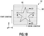
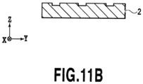
- the relief structure forming layer 2 includes a fine indented structure in the first region R1 and on one of its principal surfaces.
- an expression “a degrees to the left or right” for defining directions of extension of the indented structure may be indicated as “ ⁇ degrees”. Meanwhile, an expression “a degrees to the right” may be indicated as “ ⁇ degrees” or “a degrees”, and an expression “a degrees to the left” may be indicated as “- ⁇ degrees” as appropriate. Moreover, a certain direction of extension and a direction of extension obtained by adding 180 degrees to the certain direction of extension are deemed to be identical to each other.
- a depth of each recessed portion or a height of each projecting portion can be set in a range from 0.02 ⁇ m to 1.5 ⁇ m, for example.
- An average value of a ratio of either the depth of the recessed portion or the height of the projecting portion to the pitch thereof (hereinafter also simply referred to as an "aspect ratio”) can be set equal to or below 3. 0 or typically in a range from 1.0 to 0.15.
- present invention also encompasses structures shown in Figs. 9A to 11B as the indented structures to be provided in the first region R1.
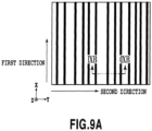
- Fig. 9A is a plan view schematically showing a structure in which multiple straight recessed portions (grooves) extend in the first direction and pitches of the recessed portions are not constant
- Fig. 9B is a cross-sectional view taken along the IXB-IXB line in Fig. 9A .
- the recessed portions are blackened in Fig. 9A .
- each recessed portion can be set in a range from 0.02 to 1.5 ⁇ m, for example.
- the average values of the ratio of the depth of the recessed portion to the pitch thereof can be set equal to or below 3.0 or typically in a range from 1.0 to 0.15.
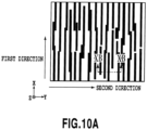
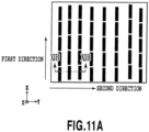
- Fig. 10A is a plan view schematically showing a structure in which the recessed portions (the grooves) extending in the first direction are arranged at random
- Fig. 10B is a cross-sectional view taken along the XB-XB line in Fig. 10A .
- the recessed portions (the grooves) are blackened in Fig. 10A .
- some rectangular recessed portions may be partially combined with one another in a plan view so as to collectively form a polygonal recessed portion in a plan view.
- a sum of lengths of sides along the first direction is preferably set twice or more as much as a sum of lengths of sides along the second direction.
- the contour of the polygon means a contour of the recessed portion formed by cutting the recessed portion out along an X-Y plane at its average depth.
- the pitches of the recessed portions in the second direction are set in a range from 0.1 to 3.0 mm or preferably in a range from 0.4 to 0.7 ⁇ m, which may be either constant or not constant.
- an interval between two of the recessed portions in the first direction be sufficiently smaller than the width (the short side of the rectangle) of each recessed portion, which is defined to be equal to or below 1/2, for example. While a lower limit of the interval between the recessed portions is not limited to a particular value, the lower limit may be set equal to or above 1/10 in view of the ease of manufacture.
- each recessed portion may extend in a direction tilted by an angle within 10 degrees to the left or right from the first direction.
- the above description of the recessed portions can replace the description of the projecting portions.
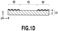
- the relief structure forming layer 2 includes a fine indented structure and/or a flat surface in the second region R2 to be provided on the one principal surface thereof.
- the indented structure extends in the second direction, which is orthogonal to the first direction, in the second region R2.
- the indented structure may extend in the second region R2 not only in the second direction but also in a direction tilted by an angle within 65 degrees to the left or right from the second direction.
- the indented structure may extend in the second region R2 not only in one direction but also in two or more directions as long as each of the directions of extension is either the second direction or a direction tilted by an angle within 65 degrees to the left or right from the second direction.
- the indented structure may have a cross-grating structure (a lattice structure) in a plan view. In the meantime, the indented structure may extend discontinuously.
- a cross section perpendicular to the direction of extension of the indented structure can take the form of a Vshape, a U-shape (a sinusoidal curve shape), a tapered shape such as a trapezoidal shape, or a rectangular shape, for instance.
- Fig. 1D depicts the case where the cross-sectional shape is the U-shape.
- a depth of each recessed portion or a height of each projecting portion can be set in a range from 0.02 ⁇ m to 1.5 ⁇ m, for example.
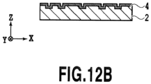
- the pitches in the structure including the recessed portions with the non-constant pitches as shown in Figs. 12A and 12B are not limited to particularly pitches.
- the pitches can vary in a range from 0.1 to 3.0 ⁇ m or preferably in a range from 0.4 to 0.7 ⁇ m.
- each recessed portion can be set in a range from 0.02 to 1.5 ⁇ m, for example.
- each recessed portion is typically rectangular in a plan view, of which short sides and long sides extend along the first direction and the second direction, respectively.
- a ratio of the long side to the short side is preferably equal to or above 1.5.
- the pitches of the recessed portions in the first direction are set in a range from 0.1 to 3.0 mm or preferably in a range from 0.4 to 0.7 ⁇ m, which may be either constant or not constant.
- each recessed portion can be set in a range from 0.02 to 1.5 ⁇ m, for example.
- the average values of the ratio of the depth of the recessed portion to the pitch thereof can be set equal to or below 3.0 or typically in a range from 1.0 to 0.15.
- each recessed portion is typically rectangular in a plan view, of which short sides and long sides extend along the first direction and the second direction, respectively.
- a ratio of the long side to the short side is preferably equal to or above 1.5.
- each recessed portion may extend in a direction tilted by an angle within 65 degrees to the left or right from the second direction.
- the above description of the recessed portions can replace the description of the projecting portions.
- the relief structure forming layer 2 may include any of flat surfaces described below, which are provided in the second region R2.
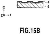
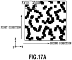
- Figs. 15A to 17B are schematic diagrams showing modified examples of flat surfaces to be provided in the second region R2.
- the recessed portions are blackened in Figs. 15A , 16A , and 17A .
- Fig. 15A is a plan view schematically showing a flat surface including recessed portions
- Fig. 15B is a cross-sectional view taken along the XVB-XVB line in Fig. 15A
- an outer shape of each recessed portion is a square in a plan view as shown in Fig. 15A .
- present invention is not limited to this configuration, and a rectangle, a circle, and the like are also included, for instance.
- a ratio of length of a side along the first direction to a side along the second direction is preferably set in a range from 0.66 to 1.5.
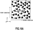
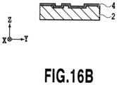
- Fig. 16A is a plan view schematically showing a flat surface including combination of two types of recessed portions
- Fig. 16B is a cross-sectional view taken along the XVIB-XVIB line in Fig. 16A .
- an outer shape of the bottom surface of each recessed portion is formed of two types of squares in different sizes as shown in Fig. 16A , and polygons are formed in part with the two types of squares overlapping one another.
- the outer shape of the bottom surface of each recessed portion may also be formed of combination of multiple types of squares, rectangles, and circles in difference sizes.
- a sum of lengths of sides along the first direction is set preferably from 0.66 to 1.5 times, or more preferably one time as much as a sum of lengths of sides along the second direction.
- the contour of the polygon means a contour of the recessed portion formed by cutting the recessed portion out along an X-Y plane at its average depth.
- a section surrounded by the contour of each recessed portion may be paved with squares each having the area equivalent to a one-hundredth of the area of this section, so that each of the sums of the lengths of the sides along the first direction and the second direction may be calculated approximately.
- a section surrounded by the contour may be paved with squares each having the area equivalent to a one-hundredth of the area of this section, so that a ratio of the sum of the lengths of the sides along the first direction to the sum of the lengths of the sides along the second direction may be calculated approximately.
- the description of the recessed portions can replace the description of the projecting portions.
- a film thickness of the relief structure forming layer 2 can be set equal to or below 3.0 mm.
- the "film thickness" of a layer means an average value of distances each between a point on one of surfaces of the layer and a foot of a perpendicular extending toward the other surface of the layer.
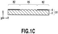
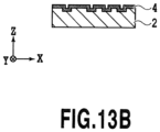
- the first layer 4 is the layer provided on the relief structure forming layer 2, this layer is not provided on the entire surface of the relief structure forming layer 2 but is provided either only in the second region R2 or in the second region R2 and in part of the first region R1. In the example of the laminate 10 shown in Fig. 1A , the first layer 4 is provided only in the second region R2 as shown in Figs. 1C and 1D .
- the laminate 10 of present invention may include the second layer.
- the second layer is provided in such a way as to cover at least the first layer 4.
- the second layer may or may not have such a surface shape that corresponds to the surface shape of the relief structure forming layer 2.
- a film thickness of the second layer may vary depending on the usage of the laminate 10. For instance, when the laminate 10 is used as an optical element, the film thickness may be set in a range from about 10 nm to 300 nm. When the laminate 10 is used as an electronic circuit, the film thickness may be set in a range from about 10 nm to 300 nm.
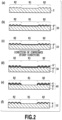
- Figs. 2(a) to 2(f) are schematic cross-sectional views sequentially showing the respective steps of the manufacturing method of the laminate shown in Fig. 1A , in which Fig. 2(a) is a cross-sectional view for explaining a step of forming the relief structure forming layer 2, Fig. 2(b) is a cross-sectional view for explaining a step of forming a first material laminate 20, Fig. 2(c) is a cross-sectional view for explaining a step of locating the first material laminate 20, Fig. 2(d) is a cross-sectional view for explaining a step of forming a second material laminate 30, Fig.
- FIG. 2(e) is a cross-sectional view for explaining a step of forming a laminate 40 by sequentially forming a first layer 4' and a second layer 6 in the second region R2 of the relief structure forming layer 2
- Fig. 2(f) is a cross-sectional view for explaining a step of removing the second layer 6 from the laminate 40 shown in Fig. 2(e) .
- Fig. 2(f) corresponds to Fig. 1D .
- the relief structure forming layer 2 having the principal surface including the first region R1 and the second region R2 is formed as shown in Fig. 2(a) .
- the relief structure forming layer 2 includes the indented structure extending in the first direction or the direction tilted by an angle within 10 degrees to the left or right from the first direction in a plan view.
- the relief structure forming layer 2 includes the indented structure extending in the second direction orthogonal to the first direction or a direction tilted by an angle within 65 degrees to the left or right from the second direction, and/or a flat surface in a plan view.
- the relief structure forming layer 2 may be formed with a method of coating a thermoplastic resin on a base material and pressing an original plate (a mold) including the aforementioned projecting portions against the resin while applying heat thereto.
- thermoplastic resin usable herein include acrylic-based resins, epoxy-based resins, cellulose-based resins, vinyl-based resins, and mixtures or copolymers thereof.
- the relief structure forming layer 2 may be formed with a method of coating a thermosetting resin on a base material, applying heat thereto while pressing an original plate including the aforementioned projecting portions against the resin, and then removing the original plate.
- thermosetting resin usable in this case include urethane resins, melamine-based resins, epoxy resins, phenol-based resins, and mixtures or copolymers thereof.
- a urethane resin can be obtained, for example, by adding polyisocyanate as a cross-linker to any of acrylic polyol and polyester polyol containing a reactive hydroxyl group, thereby cross-linking these materials.
- the relief structure forming layer 2 may be formed with a method of coating a radiation curable resin on a base material, curing the resin by irradiating the resin with radiation such as ultraviolet rays while pressing an original plate against the resin, and then removing the original plate.
- the relief structure forming layer 2 may be formed with a method of feeding the resin to a space between the base material and the original plate, curing the resin by irradiating the resin with the radiation, and then removing the original plate.
- Such a radiation curable resin typically contains a polymerizable compound and an initiator.
- a photo-radical polymerizable compound can be used as the polymerizable compound.
- Any of a monomer, an oligomer, and a polymer containing an ethylenically unsaturated bond or an ethylenically unsaturated group can be used as the photo-radical polymerizable compound.
- photo-radical polymerizable compound usable herein examples include: monomers such as 1,6-hexanediol, neopentyl glycol diacrylate, trimethylol propane triacrylate, pentaerythritol triacrylate, pentaerythritol tetraacrylate, pentaerythritol pentaacrylate, and dipentaerythritol hexaacrylate; oligomers such as epoxy acrylate, urethane acrylate, and polyester acrylate; and polymers such as urethane-modified acrylic resins and epoxy-modified acrylic resins.
- monomers such as 1,6-hexanediol, neopentyl glycol diacrylate, trimethylol propane triacrylate, pentaerythritol triacrylate, pentaerythritol tetraacrylate, pentaerythritol pentaacrylate, and dipentaeryth
- a photo-radial polymerization initiator can be used as the initiator.
- the photo-radial polymerization initiator usable herein include: benzoin-based compounds such as benzoin, benzoin methyl ether, and benzoin ethyl ether; anthraquinone-based compounds such as anthraquinone and methyl anthraquinone; phenylketone-based compounds such as acetophenone, diethoxyacetophenone, benzophenone, hydroxyacetophenone, 1-hydroxycyclohexyl phenyl ketone, ⁇ -aminoacetophenone, and 2-methyl-1-(4-methylthio phenyl)-2-morpholino propan-1-one; benzyl dimethyl ketal; thioxanthone; acyl phosphine oxide; and Michler's ketone.
- a mixture of the photo-radical polymerizable compound and the photo-cationic polymerizable compound can be used as the polymerizable compound.
- a mixture of the photo-radial polymerization initiator and the photo-cationic polymerization initiator can be used as the initiator.
- a polymerization initiator that can function as an initiator for both the photo-radical polymerization and the photo-cationic polymerization may be used in this case. Examples of such an initiator usable herein include the aromatic iodonium salts and the aromatic sulfonium salts.
- the radiation curable resin may further contain a sensitizing dye, a dye, a pigment, a polymerization inhibitor, a leveling agent, an antifoaming agent, an antisagging agent, an adhesion improver, a coating surface modifier, a plasticizer, a nitrogen-containing compound, a cross-linker such as an epoxy resin, and a release agent, or a combination thereof.
- the resin may further contain a non-reactive resin.
- the non-reactive resin usable herein include the thermoplastic resins and/or the thermosetting resins mentioned above.
- the above-mentioned original plate used for forming the relief structure forming layer 2 can be manufactured by use of an electron beam drawing apparatus or a nanoimprinting apparatus, for example. In this way, it is possible to form the above-mentioned multiple recessed portions or projecting portions with high accuracy.
- the indented structure to be provided on the relief structure forming layer 2 may be a structure obtained by repeatedly imposing a unit structure with its area in a range from 4 ⁇ m 2 to 10000 ⁇ m 2 . In this case, an amount of data used for the drawing can be significantly reduced since a pattern to form the unit structure can be used repeatedly.
- the formation of relief structures (the indented structures) of the relief structure forming layer 2 may be conducted by using any of a "pressing method” disclosed in Japanese Patent No. 4194073 , a “casting method” disclosed in Japanese Utility Model Registration No. 2524092 , and a "photopolymer method” disclosed in Japanese Patent Laid-Open No. 2007-118563 , for example.
- the first material laminate 20 located in the step (c) is conveyed and the second material being different from the first material is vapor-phase deposited from an oblique direction onto the surface of the first material laminate on which the first material is deposited.
- the second material laminate 30 is formed ( Fig. 2(d) ).
- a method of conveying the first material laminate 20 is not limited to a particular method as long as the method is capable of conveying the first material laminate 20 in the first direction, in which the indented structure in the first region R1 of the first material laminate 20 extends, at the time of the vapor-phase deposition of the second material.
- a method of conveying the first material laminate 20 fixed to a carrier film may be used. In the case of conveying the first material laminate 20 in a roll-to-roll method and where the first material laminate 20 has the form of a long and rolled-up roll, then the first material laminate 20 itself may be conveyed.
- the deposition of the second material is preferably conducted with a uniform density in the in-plane direction parallel to the principal surface of the relief structure forming layer 2. Specifically, the deposition is preferably conducted in such a way that a ratio of an amount of the second material at a position in the first region R1 to the apparent area of the first region R1 is equal to a ratio of an amount of the second material at a position in the second region R2 to the apparent area of the second region R2.
- the second material is the material different from the first material.
- the second material is a material that does not react with (get dissolved in) a reactive gas or liquid used in the step (e) to be described later. This is due to a reason that the above-mentioned layer made of the second material functions as a mask layer in the second region R2 to protect the first material layer 4" against the reactive gas or the like so that the first material layer 4" can be prevented from being eroded by the reactive gas or the like.
- the second material may be determined in consideration of the usage of the laminate.
- examples of the second material include silicon oxides (SiO x ,1 ⁇ X ⁇ 2).
- silicon oxide SiO x , 1 ⁇ X ⁇ 2
- the second material evaporated from the vapor deposition source 120 reaches the surface of the first material layer 4".
- the second material comes close to the surface of the first material layer 4" in the oblique direction, and gets deposited on the surface of the first material layer 4".
- the second material is obliquely deposited on the surface of the first material layer 4".
- the second material comes close obliquely to the surface of the first material laminate 20 and gets deposited on the surface.
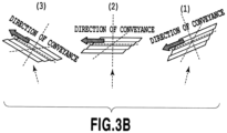
- Fig. 3B includes schematic diagrams showing aspects of the deposited surface in the first region R1 of the first material laminate 20 when the first material laminate 20 are passed through the positions (1), (2), and (3) in Fig. 3A .
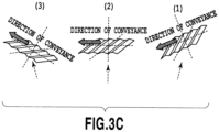
- Fig. 3C includes schematic diagrams showing aspects of the deposited surface in the second region R2 of the first material laminate 20 when the first material laminate 20 are passed through the positions (1), (2), and (3) in Fig. 3A .
- the indented structure on the deposited surface in the first region R1 of the first material laminate 20 extends in the first direction, and the direction of extension thereof coincides with the direction of conveyance of the first material laminate 20.
- the indented structure on the deposited surface in the second region R2 extends in the second direction, and the direction of extension thereof is orthogonal to the direction of conveyance of the first material laminate 20.
- Fig. 3C the direction of extension of the indented structure formed on the surface of the first material layer 4" in the second region R2 is orthogonal to the direction of conveyance of the first material laminate 20. For this reason, a shade that does not allow entry of the second material is less likely to be created as compared to the case of the first region R1. As a consequence, a density of a film formed of the second material is higher in the second region R2 because pores by the deposition of the second material are hardly formed therein.
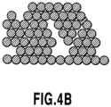
- Fig. 4B shows an estimated cross-sectional view of the form of deposition of the second material in the second region R2.
- the second material laminate 30 is exposed to the reactive gas or liquid that reacts with the first material.
- the pores are formed in a second material layer 6' in the first region R1 ( Fig. 4A ) whereas such pores are rare in the second region R2 ( Fig. 4B ).
- the reactive gas or liquid is more likely to permeate the second material layer 6' through the pores in the second material layer 6' and to come into contact with the first material layer 4" than in the second region R2.
- the first material layer 4" and the second material layer 6' are removed only in the first region R1.
- the first layer 4' and the second layer 6 may be included in this order in part of the first region R1.
- the etching may be stopped before the first layer 4' in the first region R1 is completely removed.
- the second layer 6 may be partially left in the first region R1.
- an etchant that dissolves the first material as the reactive gas or liquid
- an alkaline solution such as a sodium hydroxide solution, a sodium carbonate solution, and a potassium hydroxide solution
- an acidic solution such as hydrochloric acid, nitric acid, sulfuric acid, and acetic acid.
- an etching gas capable of gasifying the first material may be used.
- the reactive gas or liquid that does not dissolve the second material should be selected.
- An example of a method of removing the second layer 6 includes a method of exposing the laminate 40 formed in the step (e) to a reactive gas or liquid, which is reactive with the second material constituting the second layer 6 but is not reactive with the first material constituting the first layer 4'.
- an etchant that dissolves the second material as the reactive gas or liquid
- an alkaline solution such as a sodium hydroxide solution, a sodium carbonate solution, and a potassium hydroxide solution
- an acidic solution such as hydrochloric acid, nitric acid, sulfuric acid, and acetic acid.
- an etching gas capable of gasifying the second material may be used.
- the laminate 10 including the relief structure forming layer 2 having the principal surface including the first region R1 and the second region R2, and the first layer 4 provided either only in the second region R2 or in the second region R2 as well as in part of the first region R1 of the relief structure forming layer 2 can be manufactured by conducting the above-described steps (a) to (f).
- laminate and the manufacturing method thereof according to present invention described above may also include the following embodiments.
- the first layer 4 may include a multilayer film formed by laminating a mirror layer, a spacer layer, and a half mirror layer in this order from the relief structure forming layer 2 side, for example.
- the spacer layer typically contains a dielectric material.
- a refractive index of the dielectric material is preferably set equal to or below 1.65.
- the dielectric material is preferably transparent. Examples of such a dielectric material include SiO 2 and MgF 2 .
- a thickness of the spacer layer can be set in a range from 5 to 500 nm, for example.
- This thickness is preferably set in a range from 30 to 80 nm in the case of using a metal oxide such as titanium oxide or a metal sulfide salt such as zinc sulfide, each of which represents a high refractive-index material with high transparency. Meanwhile, the thickness is preferably set in a range from 5 to 45 nm in the case of using a metal such as aluminum which has high reflectance and a high light shielding property.
- An oxidizing agent capable of oxidizing the material of the first layer 4 can be used as the abovementioned reactive gas or liquid.
- the oxidizing agent usable herein include: oxygen; ozone; halogens; halides including chlorine dioxide, hypohalous acids, halous acids, sub-halogen acids, hyperhalous acids, salts thereof, and the like; inorganic peroxides including hydrogen peroxide, persulfates, peroxocarbonates, peroxosulfates, peroxophosphates, and the like; organic peroxides including benzoyl peroxide, t-butyl hydroperoxide, cumene hydroperoxide, diisopropylbenzene hydroperoxide, performic acid, peracetic acid, perbenzoic acid, and the like; metals and metal compounds including cerium salts, Mn (III), Mn (IV) and Mn (VI) salts, silver salts, copper salts, chromium salts, cobalt salts, di
- a reducing agent capable of reducing the material of the first layer 4 can be used as the abovementioned reactive gas or liquid.
- the reducing agent to be used herein include: hydrogen sulfide, sulfur dioxide, hydrogen fluoride, alcohols, carboxylic acids, hydrogen gas, hydrogen plasma, remote hydrogen plasma, diethylsilane, ethylsilane, dimethylsilane, phenylsilane, silane, disilane, aminosilane, borane, diborane, alane, germane, hydrazine, ammonia, methylhydrazine, 1,1-dimethylhydrazine, 1,2-dimethylhydrazine, t-butylhydrazine, benzylhydrazine, 2-hydrazinoethanol, 1-n-butyl-1-phenylhydrazine, phenylhydrazine, 1-naphthylhydrazine, 4-chlorophenylhydrazine, 1,
- a surface of each layer may also be subjected to any of a plasma treatment, a corona treatment, and a flame treatment.
- the direction of extension of the indented structure in each of the first region and the second region can be set in such a way as to define a specific angle.
- This makes it possible to constitute complex drawing patterns when either the metal reflective layer or the transparent reflective layer of the metal oxide or the like is provided as the first layer in both of the first region and the second region.
- the laminate can bring about a two-image switching effect (a changing effect) when the first region and the second region are provided with the indented structures having the directions of extension being orthogonal to each other but in the same shape with the aspect ratio of 0.2 and the pitches of 1 mm.
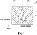
- the second region includes the two subregions in the example shown in Fig. 5
- the number of subregions is not limited only to two and the second region may include three or more subregions.
- the first region includes two subregions with indented structures, which have the same direction of extension but different pitches, depths, and aspect ratios.
- the first region includes: a first subregion R1-1 which has an indented structure extending in the first direction, and has the pitch of 600 nm, the depth of 150 nm, and the aspect ratio of 0.25; and a first subregion R1-2 which has an indented structure extending in the first direction, and has the pitch of 400 nm, the depth of 400 nm, and the aspect ratio of 1.00.
- This embodiment is not limited to the directions of extension of the indented structures shown in Fig. 6 .
- the direction of extension of each indented structure in the first region may be set in the first direction or a direction tilted by an angle within 10 degrees to the left or right from the first direction.
- this embodiment can adopt those described in the first embodiment.
- the second region includes the two subregions which have the indented structures with the directions of extension being different from each other. Specifically, the second region includes the second subregion R2-1 which has the indented structure extending in the direction tilted by 45 degrees to the right (+45 degrees) from the second direction, and the second subregion R2-2 which has the indented structure extending in the direction tilted by 45 degrees to the left (-45 degrees) from the second direction.
- This embodiment is not limited to the directions of extension of the indented structures shown in Fig. 6 .
- the direction of extension of each indented structure in the second region may be set in the second direction or a direction tilted by an angle within 65 degrees to the left or right from the second direction.
- Fig. 6 illustrates the example of the subregions in the second region, which have the indented structures extending in the directions different from each other.
- the second region may include subregions having at least any of the following features that are different from each other, namely, the directions of extension, the pitches, and the depths (the heights) of the indented structures.
- each of the first region and second region includes the two subregions in Fig. 6
- the number of subregions is not limited only to two and each of the first region and the second region may include three or more subregions.
- the depth of the indented structure provided in the subregion R1-2 may be increased as in the laminate 10 shown in Fig. 6 .
- adhesion between two upper and lower layers interposing the indented structure is improved by an anchor effect (a wedge effect).
- a similar anchor effect can also be obtained by forming the indented structure having a rectangular cross-sectional shape instead of using the indented structure of a high aspect ratio.
- the laminate 10 according to the third embodiment can be manufactured in accordance with the method described in the previous section ⁇ Manufacturing Method of Laminate>.
- the relief structure forming layer may be formed in the step (a) in such a way that the first region R1 and the second region R2 have the desired indented structures, and then the steps (b) to (f) may be carried out.
- a laminate of this embodiment similar to that of third embodiment includes the first region and second region with multiple subregions.
- at least any of the following features are different from each other, namely, the directions of extension, the pitches, and the depths (the heights) of the indented structures.
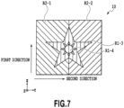
- Fig. 7 is a schematic plan view showing the laminate 10 manufactured according to the fourth embodiment of present invention.
- the first region includes two subregions with indented structures, which have the pitches and the aspect ratios being different from each other.
- a first subregion R1-3 extends in the first direction and forms a drawing pattern of a star including a diffraction structure having a sinusoidal cross-sectional shape with the pitch of 600 nm, the depth of 150 nm, and the aspect ratio of 0.25.
- a first subregion R1-4 extends in the first direction and forms a drawing pattern of the sun including a diffraction structure having a sinusoidal cross-sectional shape with the pitch of 750 nm, the depth of 150 nm, and the aspect ratio of 0.20.
- the second region includes the two subregions which have the indented structures with the directions of extension being different from each other. Specifically, the second region includes the second subregion R2-1 which has the indented structure extending in the direction tilted by 45 degrees to the right (+45 degrees) from the second direction, and the second subregion R2-2 which has the indented structure extending in the direction tilted by 45 degrees to the left (-45 degrees) from the second direction.
- This embodiment is not limited to the example shown in Fig. 7 in light of the directions of extension, the pitches, the depths, and the aspect ratios of the indented structures. This embodiment can also adopt those described in the first embodiment.
- the first layer is taken away in the first region (the first subregions). Accordingly, it is also possible to obtain a diffraction effect in the first subregions by providing the first region with a third layer made of a highly refractive material being different from the material of the first layer. Specifically, when aluminum is used as the material of the first layer while zinc sulfide being a highly transparent and highly refractive material is used as the material of the third layer, bright diffraction light attributed to aluminum is observed in each of the second subregions R2-1 and R2-2 while highly transparent diffraction light can be obtained in each of the first subregions R1-3 and R1-4.
- the laminate 10 according to the fourth embodiment can be manufactured in accordance with the method described in the previous section ⁇ Manufacturing Method of Laminate>.
- the relief structure forming layer may be formed in the step (a) in such a way that the first region R1 and the second region R2 have the desired indented structures, and then the steps (b) to (f) may be carried out.
- the third layer if the third layer is provided, then the material of the third layer may be deposited so as to form a desired film thickness on the entire surfaces of the first and second regions on the first layer side of the laminate 10 obtained in the step (f).
- a publicly known coating method or vapor-phase deposition method can be used as the method of depositing the material of the third layer.
- a coating method such as spray coating can be used as the coating method.
- the vapor-phase deposition method it is possible to use any of vapor-deposition methods of a vacuum deposition method, a sputtering method, a chemical vapor deposition method (CVD method), and the like.
- a highly transparent and highly refractive material such as zinc sulfide and titanium oxide can be used as the material of the third layer.
- This embodiment has such a feature that the first layer, the second layer, and an etching mask layer are included in this order in part of the first region of the relief structure forming layer of the first embodiment.
Landscapes
- Physics & Mathematics (AREA)
- General Physics & Mathematics (AREA)
- Optics & Photonics (AREA)
- Engineering & Computer Science (AREA)
- Manufacturing & Machinery (AREA)
- Chemical & Material Sciences (AREA)
- Chemical Kinetics & Catalysis (AREA)
- General Chemical & Material Sciences (AREA)
- Laminated Bodies (AREA)
- Diffracting Gratings Or Hologram Optical Elements (AREA)
- Shaping Of Tube Ends By Bending Or Straightening (AREA)
- Credit Cards Or The Like (AREA)
Claims (2)
- Verfahren zur Herstellung eines Laminats (10), das eine Reliefstruktur-bildende Schicht (2) mit einer Hauptoberfläche, die erste und zweite Bereiche (R1, R2) einschließt, und eine erste Schicht (4), die entweder nur in dem zweiten Bereich (R2) oder in dem zweiten Bereich (R2) sowie in einem Teil des ersten Bereichs (R1) der Reliefstruktur-bildenden Schicht (2) vorliegt, wobei das Verfahren die folgenden Schritte umfasst:einen Schritt (a) der Ausbildung der Reliefstruktur-bildenden Schicht (2), die den ersten Bereich (R1) mit einer eingekerbten Struktur, die sich in einer ersten Richtung oder einer Richtung, die um einen Winkel innerhalb von 10 Grad nach links oder rechts von der ersten Richtung in Draufsicht geneigt ist, erstreckt, und den zweiten Bereich (R2) mit einer flachen Oberfläche und/oder einer eingekerbten Struktur, die sich in einer zweiten Richtung senkrecht zu der ersten Richtung oder einer Richtung, die um einen Winkel innerhalb von 65 Grad nach links oder rechts von der zweiten Richtung in Draufsicht geneigt ist, erstreckt, umfasst;einen Schritt (b) der Ausbildung eines ersten Materiallaminats (20) mit einer Oberflächenform, die einer Oberflächenform der Reliefstruktur-bildenden Schicht (2) entspricht, indem ein erstes Material verschieden von einem Material der Reliefstruktur-bildenden Schicht (2) in ersten und zweiten Bereichen (R1, R2) der Reliefstruktur-bildenden Schicht (2) abgeschieden wird;einen Schritt (c) der Positionierung des ersten Materiallaminats (20) in einer Vorrichtung zur Abscheidung aus der Gasphase derart, dass die erste Richtung in Schritt (a) mit einer Richtung der Förderung des ersten Materiallaminats (20) zusammenfällt;einen Schritt (d) der Ausbildung eines zweiten Materiallaminats (30) durch Fördern des positionierten ersten Materiallaminats (20) und Abscheiden eines zweiten Materials verschieden von dem ersten Material aus der Gasphase aus schräger Richtung auf einer Oberfläche des ersten Materiallaminats (20), auf dem das erste Material abgeschieden ist;einen Schritt (e) der Ausbildung eines Laminats (40), das die erste Schicht (4) und eine zweite Schicht (6) in dieser Reihenfolge umfasst, wobei die Schichten entweder nur in dem zweiten Bereich (R2) oder in dem zweiten Bereich (R2) und in einem Teil des ersten Bereichs (R1) der Reliefstruktur-bildenden Schicht (2) vorliegen, indem das zweite Materiallaminat (30) einem reaktiven Gas oder einer reaktiven Flüssigkeit, die mit dem ersten Material reagieren kann, ausgesetzt wird; undeinen Schritt (f), in dem die zweite Schicht (6) von dem in Schritt (e) ausgebildeten Laminat (10) entfernt wird.
- Verfahren zur Herstellung eines Laminats (10), das eine Reliefstruktur-bildende Schicht (2) mit einer Hauptoberfläche, die erste und zweite Bereiche (R1, R2) einschließt, und eine erste Schicht (4) und eine zweite Schicht (6), die in dieser Reihenfolge, entweder nur in dem zweiten Bereich (R2) oder in dem zweiten Bereich (R2) sowie in einem Teil des ersten Bereichs (R1) der Reliefstruktur-bildenden Schicht (2) vorliegen, wobei das Verfahren die folgenden Schritte umfasst:einen Schritt (a) der Ausbildung der Reliefstruktur-bildenden Schicht (2), die den ersten Bereich (R1) mit einer eingekerbten Struktur, die sich in einer ersten Richtung oder einer um einen Winkel innerhalb von 10 Grad nach rechts oder links von der ersten Richtung in Draufsicht geneigt ist, erstreckt, und den zweiten Bereich (R2) mit einer flachen Oberfläche und/oder einer eingekerbten Struktur, die sich in einer zweiten Richtung senkrecht zu der ersten Richtung oder in einer um einen Winkel innerhalb von 65 Grad nach links oder rechts von der zweiten Richtung in Draufsicht geneigten Richtung erstreckt, umfasst;einen Schritt (b) der Ausbildung eines ersten Materiallaminats (20) mit einer Oberflächenform, die einer Oberflächenform der Reliefstruktur-bildenden Schicht (2) entspricht, indem ein erstes Material verschieden von einem Material der Reliefstruktur-bildenden Schicht (2) in ersten und zweiten Bereichen (R1, R2) der Reliefstruktur-bildenden Schicht (2) abgeschieden wird;einen Schritt (c) der Positionierung des ersten Materiallaminats (20) in einer Vorrichtung zur Abscheidung aus der Gasphase derart, dass die erste Richtung in Schritt (a) mit einer Richtung der Förderung des ersten Materiallaminats (20) zusammenfällt;einen Schritt (d) der Ausbildung eines zweiten Materiallaminats (30) durch Fördern des positionierten ersten Materiallaminats (20) und Abscheiden eines zweiten Materials verschieden von dem ersten Material aus der Gasphase aus schräger Richtung auf einer Oberfläche des ersten Materiallaminats (20), auf dem das erste Material abgeschieden ist; undeinen Schritt (e), in dem das zweite Materiallaminat (30) einem reaktiven Gas oder einer reaktiven Flüssigkeit, die mit dem ersten Material reagieren kann, ausgesetzt wird.
Priority Applications (1)
| Application Number | Priority Date | Filing Date | Title |
|---|---|---|---|
| EP21195251.0A EP3951449A1 (de) | 2015-06-02 | 2016-06-02 | Laminat und herstellungsverfahren dafür |
Applications Claiming Priority (2)
| Application Number | Priority Date | Filing Date | Title |
|---|---|---|---|
| JP2015112623 | 2015-06-02 | ||
| PCT/JP2016/002688 WO2016194385A1 (ja) | 2015-06-02 | 2016-06-02 | 積層体およびその製造方法 |
Related Child Applications (2)
| Application Number | Title | Priority Date | Filing Date |
|---|---|---|---|
| EP21195251.0A Division EP3951449A1 (de) | 2015-06-02 | 2016-06-02 | Laminat und herstellungsverfahren dafür |
| EP21195251.0A Division-Into EP3951449A1 (de) | 2015-06-02 | 2016-06-02 | Laminat und herstellungsverfahren dafür |
Publications (4)
| Publication Number | Publication Date |
|---|---|
| EP3306362A1 EP3306362A1 (de) | 2018-04-11 |
| EP3306362A4 EP3306362A4 (de) | 2018-05-09 |
| EP3306362B1 EP3306362B1 (de) | 2021-11-03 |
| EP3306362B2 true EP3306362B2 (de) | 2025-07-02 |
Family
ID=57440997
Family Applications (2)
| Application Number | Title | Priority Date | Filing Date |
|---|---|---|---|
| EP16802825.6A Active EP3306362B2 (de) | 2015-06-02 | 2016-06-02 | Laminat und herstellungsverfahren dafür |
| EP21195251.0A Pending EP3951449A1 (de) | 2015-06-02 | 2016-06-02 | Laminat und herstellungsverfahren dafür |
Family Applications After (1)
| Application Number | Title | Priority Date | Filing Date |
|---|---|---|---|
| EP21195251.0A Pending EP3951449A1 (de) | 2015-06-02 | 2016-06-02 | Laminat und herstellungsverfahren dafür |
Country Status (6)
| Country | Link |
|---|---|
| US (2) | US10518500B2 (de) |
| EP (2) | EP3306362B2 (de) |
| JP (1) | JPWO2016194385A1 (de) |
| KR (1) | KR102408530B1 (de) |
| CN (2) | CN112859222B (de) |
| WO (1) | WO2016194385A1 (de) |
Families Citing this family (5)
| Publication number | Priority date | Publication date | Assignee | Title |
|---|---|---|---|---|
| DE102018004062A1 (de) * | 2018-05-18 | 2019-11-21 | Giesecke+Devrient Currency Technology Gmbh | Sicherheitselement mit Mikroreflektoren |
| EP3955032B1 (de) | 2019-04-09 | 2024-04-24 | Toppan Printing Co., Ltd. | Optische struktur, transferfolie, gegenstand und verfahren zur herstellung einer optischen struktur |
| US20220035251A1 (en) * | 2020-07-31 | 2022-02-03 | Applied Materials, Inc. | Methods to fabricate 2d wedge and localized encapsulation for diffractive optics |
| WO2022030563A1 (ja) * | 2020-08-04 | 2022-02-10 | 凸版印刷株式会社 | 積層体、カード、カードの製造方法、カードの作製方法、カード用情報記録シートおよびそれを用いたカード |
| JP7537211B2 (ja) * | 2020-09-29 | 2024-08-21 | Toppanホールディングス株式会社 | 表示体 |
Family Cites Families (67)
| Publication number | Priority date | Publication date | Assignee | Title |
|---|---|---|---|---|
| JPS6140272U (ja) * | 1984-08-15 | 1986-03-14 | 凸版印刷株式会社 | カ−ド |
| US5300169A (en) * | 1991-01-28 | 1994-04-05 | Dai Nippon Printing Co., Ltd. | Transfer foil having reflecting layer with fine dimple pattern recorded thereon |
| JP2524092Y2 (ja) | 1991-02-26 | 1997-01-29 | 凸版印刷株式会社 | ホログラムシート |
| DE4404128A1 (de) * | 1993-02-19 | 1994-08-25 | Gao Ges Automation Org | Sicherheitsdokument und Verfahren zu seiner Herstellung |
| CH690067A5 (de) | 1995-08-10 | 2000-04-14 | Ovd Kinegram Ag | Verfahren zur Herstellung teilmetallisierter Gitterstrukturen. |
| US7667895B2 (en) * | 1999-07-08 | 2010-02-23 | Jds Uniphase Corporation | Patterned structures with optically variable effects |
| DE10007916A1 (de) * | 2000-02-21 | 2001-08-23 | Giesecke & Devrient Gmbh | Mehrschichtige, laminierte Karte mit eingelagertem, Reliefstrukturen aufweisenden Sicherheitselement |
| JP4319807B2 (ja) * | 2002-05-29 | 2009-08-26 | 大日本印刷株式会社 | 光回折構造による隠しパターン及びその作製方法 |
| JP4194073B2 (ja) | 2002-09-25 | 2008-12-10 | 大日本印刷株式会社 | 光回折構造体 |
| WO2004053542A1 (en) * | 2002-12-12 | 2004-06-24 | Sumitomo Chemical Company, Limited | Method for producing polarizing film |
| DE10351129B4 (de) * | 2003-11-03 | 2008-12-24 | Ovd Kinegram Ag | Diffraktives Sicherheitselement mit einem Halbtonbild |
| JP2007118563A (ja) | 2005-03-11 | 2007-05-17 | Dainippon Printing Co Ltd | 転写箔及びそれを用いた画像形成物 |
| EP1832439B1 (de) * | 2006-03-06 | 2014-04-23 | JDS Uniphase Corporation | Gegenstand mit optischem Effekt |
| DE102006037431A1 (de) | 2006-08-09 | 2008-04-17 | Ovd Kinegram Ag | Verfahren zur Herstellung eines Mehrschichtkörpers sowie Mehrschichtkörper |
| JP5141078B2 (ja) * | 2007-04-04 | 2013-02-13 | 凸版印刷株式会社 | セキュリティデバイス、ラベル付き印刷物および判別方法 |
| JP4905053B2 (ja) | 2006-10-24 | 2012-03-28 | 凸版印刷株式会社 | Ovd媒体及びovd媒体を含むカード状情報媒体 |
| JP4961944B2 (ja) | 2006-10-24 | 2012-06-27 | 凸版印刷株式会社 | 表示体及び印刷物 |
| JP4259608B2 (ja) * | 2007-03-30 | 2009-04-30 | Dic株式会社 | カード状磁気記録媒体、その製造方法、転写用積層体及びその製造方法 |
| WO2008146422A1 (ja) * | 2007-05-25 | 2008-12-04 | Toppan Printing Co., Ltd. | 表示体及び情報印刷物 |
| JP5169093B2 (ja) * | 2007-09-12 | 2013-03-27 | 凸版印刷株式会社 | 偽造防止積層体、偽造防止転写箔、偽造防止シール、偽造防止媒体、及びこれらの製造方法 |
| GB0720550D0 (en) * | 2007-10-19 | 2007-11-28 | Rue De Int Ltd | Photonic crystal security device multiple optical effects |
| DE102008009296A1 (de) | 2008-02-15 | 2009-08-20 | Giesecke & Devrient Gmbh | Sicherheitselement und Verfahren zu seiner Herstellung |
| WO2009121918A1 (en) * | 2008-04-01 | 2009-10-08 | Agfa-Gevaert | Security laminates with a security feature detectable by touch |
| CA2708526C (en) | 2008-04-18 | 2012-02-21 | Toppan Printing Co., Ltd. | Display and labeled article |
| JP4998405B2 (ja) * | 2008-08-11 | 2012-08-15 | 凸版印刷株式会社 | 表示体及びラベル付き物品 |
| JP5267075B2 (ja) | 2008-11-26 | 2013-08-21 | 凸版印刷株式会社 | 表示体 |
| JP2010271653A (ja) * | 2009-05-25 | 2010-12-02 | Toppan Printing Co Ltd | 表示体、粘着ラベル、転写箔及び表示体付き物品 |
| EP2444826B1 (de) * | 2009-06-18 | 2019-05-22 | Toppan Printing Co., Ltd. | Optische vorrichtung und verfahren zu ihrer herstellung |
| DE102009032697C5 (de) * | 2009-07-09 | 2020-03-05 | Ovd Kinegram Ag | Mehrschichtkörper |
| GB0919108D0 (en) * | 2009-10-30 | 2009-12-16 | Rue De Int Ltd | Security device |
| GB0919112D0 (en) * | 2009-10-30 | 2009-12-16 | Rue De Int Ltd | Security device |
| DE102009053925A1 (de) * | 2009-11-19 | 2011-05-26 | Giesecke & Devrient Gmbh | Sicherheitselement mit Mikrostruktur |
| WO2011065160A1 (ja) | 2009-11-27 | 2011-06-03 | 凸版印刷株式会社 | 表示体及び表示体付き物品 |
| WO2011068002A1 (ja) * | 2009-12-01 | 2011-06-09 | 凸版印刷株式会社 | 表示体及びラベル付き物品 |
| EP2333727B1 (de) * | 2009-12-11 | 2018-04-04 | OpSec Security Group, Inc. | Optisch variable vorrichtungen, sicherheitsvorrichtung und -gegenstand, die diese vorrichtungen einsetzen, und zugehöriges verfahren zur herstellung dieser vorrichtungen |
| JP5724176B2 (ja) | 2009-12-16 | 2015-05-27 | 凸版印刷株式会社 | 画像形成体 |
| US20130063955A1 (en) * | 2010-04-06 | 2013-03-14 | Oy Silidomia | Laminate structure with embedded cavities and related method of manufacture |
| JP2011221330A (ja) * | 2010-04-12 | 2011-11-04 | Toppan Printing Co Ltd | 偽造防止媒体 |
| JP5909844B2 (ja) * | 2010-07-21 | 2016-04-27 | 凸版印刷株式会社 | 表示体及び情報印刷物 |
| JP2012078447A (ja) | 2010-09-30 | 2012-04-19 | Toppan Printing Co Ltd | 表示体及びラベル付き物品 |
| EP2447743B1 (de) | 2010-11-01 | 2016-10-26 | CSEM Centre Suisse d'Electronique et de Microtechnique SA - Recherche et Développement | Isotropes optisches Filter und Herstellungsverfahren dafür |
| DE102010050031A1 (de) * | 2010-11-02 | 2012-05-03 | Ovd Kinegram Ag | Sicherheitselement und Verfahren zur Herstellung eines Sicherheitselements |
| DE102011014114B3 (de) * | 2011-03-15 | 2012-05-10 | Ovd Kinegram Ag | Mehrschichtkörper und Verfahren zur Herstellung eines Mehrschichtkörpers |
| JP5929013B2 (ja) * | 2011-05-25 | 2016-06-01 | 凸版印刷株式会社 | 着色偽造防止構造体および着色偽造防止媒体 |
| GB2493369B (en) | 2011-08-02 | 2013-09-25 | Rue De Int Ltd | Improvements in security devices |
| WO2013084960A1 (ja) | 2011-12-07 | 2013-06-13 | 凸版印刷株式会社 | 表示体、転写箔、及び表示体付き物品 |
| DE102011121588A1 (de) * | 2011-12-20 | 2013-06-20 | Giesecke & Devrient Gmbh | Sicherheitselement für Sicherheitspapiere, Wertdokumente oder dergleichen |
| DE102012105571B4 (de) * | 2012-06-26 | 2017-03-09 | Ovd Kinegram Ag | Dekorelement sowie Sicherheitsdokument mit einem Dekorelement |
| DE102012108169A1 (de) * | 2012-09-03 | 2014-05-28 | Ovd Kinegram Ag | Sicherheitselement sowie Sicherheitsdokument |
| JP6229252B2 (ja) * | 2012-10-02 | 2017-11-15 | 凸版印刷株式会社 | 光学素子、用紙及び光学素子製造方法 |
| DE102012110630A1 (de) * | 2012-11-06 | 2014-05-08 | Ovd Kinegram Ag | Mehrschichtkörper sowie Verfahren zur Herstellung eines Sicherheitselements |
| CN103832114B (zh) | 2012-11-27 | 2017-10-24 | 中钞特种防伪科技有限公司 | 一种光学防伪元件及使用该光学防伪元件的产品 |
| DE102012025262B4 (de) * | 2012-12-21 | 2020-06-04 | Giesecke+Devrient Currency Technology Gmbh | Verfahren zur Herstellung eines Sicherheitselementes |
| DE102013001734A1 (de) | 2013-01-31 | 2014-07-31 | Giesecke & Devrient Gmbh | Sicherheitselement mit rinnen- oder rippenförmigen Strukturelementen |
| GB2510381B (en) | 2013-02-01 | 2015-11-04 | Rue De Int Ltd | Security devices and methods of manufacture thereof |
| DE102013105246B4 (de) * | 2013-05-22 | 2017-03-23 | Leonhard Kurz Stiftung & Co. Kg | Optisch variables Element |
| GB201313362D0 (en) * | 2013-07-26 | 2013-09-11 | Rue De Int Ltd | Security Devices and Methods of Manufacture |
| DE102013108666A1 (de) * | 2013-08-09 | 2015-03-05 | Leonhard Kurz Stiftung & Co. Kg | Verfahren zur Herstellung eines Mehrschichtkörpers sowie Mehrschichtkörper |
| CN104647936B (zh) | 2013-11-22 | 2018-05-04 | 中钞特种防伪科技有限公司 | 一种光学防伪元件及使用该光学防伪元件的光学防伪产品 |
| JP6314476B2 (ja) * | 2013-12-25 | 2018-04-25 | 凸版印刷株式会社 | 転写用積層媒体および印刷物 |
| GB201400910D0 (en) | 2014-01-20 | 2014-03-05 | Rue De Int Ltd | Security elements and methods of their manufacture |
| DE102014016051A1 (de) * | 2014-05-06 | 2015-11-12 | Giesecke & Devrient Gmbh | Sicherheitselement |
| GB201413473D0 (en) * | 2014-07-30 | 2014-09-10 | Rue De Int Ltd | Security device and method of manufacture thereof |
| DE102014011425A1 (de) * | 2014-07-31 | 2016-02-04 | Giesecke & Devrient Gmbh | Sicherheitselement zur Herstellung von Wertdokumenten |
| DE102014118366A1 (de) * | 2014-12-10 | 2016-06-16 | Ovd Kinegram Ag | Mehrschichtkörper und Verfahren zu dessen Herstellung |
| DE102015100513A1 (de) * | 2015-01-14 | 2016-07-14 | Leonhard Kurz Stiftung & Co. Kg | Verfahren und Master zum Herstellen eines Volumenhologramms |
| GB2553555B (en) * | 2016-09-08 | 2019-12-11 | De La Rue Int Ltd | Security devices and methods of manufacture thereof |
-
2016
- 2016-06-02 EP EP16802825.6A patent/EP3306362B2/de active Active
- 2016-06-02 EP EP21195251.0A patent/EP3951449A1/de active Pending
- 2016-06-02 KR KR1020177034521A patent/KR102408530B1/ko not_active Expired - Fee Related
- 2016-06-02 CN CN202110073746.5A patent/CN112859222B/zh active Active
- 2016-06-02 CN CN201680032025.7A patent/CN107615111B/zh active Active
- 2016-06-02 WO PCT/JP2016/002688 patent/WO2016194385A1/ja not_active Ceased
- 2016-06-02 JP JP2017521701A patent/JPWO2016194385A1/ja active Pending
- 2016-06-02 US US15/577,279 patent/US10518500B2/en not_active Expired - Fee Related
-
2019
- 2019-11-08 US US16/679,096 patent/US11161364B2/en active Active
Also Published As
| Publication number | Publication date |
|---|---|
| US11161364B2 (en) | 2021-11-02 |
| KR20180015143A (ko) | 2018-02-12 |
| EP3951449A1 (de) | 2022-02-09 |
| JPWO2016194385A1 (ja) | 2018-06-07 |
| US20200070467A1 (en) | 2020-03-05 |
| WO2016194385A1 (ja) | 2016-12-08 |
| CN107615111B (zh) | 2021-09-28 |
| EP3306362B1 (de) | 2021-11-03 |
| CN112859222B (zh) | 2022-08-12 |
| EP3306362A1 (de) | 2018-04-11 |
| US10518500B2 (en) | 2019-12-31 |
| US20180154605A1 (en) | 2018-06-07 |
| KR102408530B1 (ko) | 2022-06-13 |
| CN107615111A (zh) | 2018-01-19 |
| EP3306362A4 (de) | 2018-05-09 |
| CN112859222A (zh) | 2021-05-28 |
Similar Documents
| Publication | Publication Date | Title |
|---|---|---|
| EP2444826B1 (de) | Optische vorrichtung und verfahren zu ihrer herstellung | |
| US11161364B2 (en) | Laminate comprising a relief structure forming layer and a manufacturing method for same | |
| JP5578286B2 (ja) | 表示体、転写箔、及び表示体付き物品 | |
| CN104704401B (zh) | 防伪结构体及其制造方法 | |
| JP5594043B2 (ja) | 偽造防止構造体、及び偽造防止媒体 | |
| JP7417625B2 (ja) | 光学偽造防止素子及びその製造方法 | |
| WO2017032758A1 (en) | Seamless roll-to-roll nano-imprinting | |
| US8323542B2 (en) | Substrate and method of manufacturing polygon flakes | |
| JP6229252B2 (ja) | 光学素子、用紙及び光学素子製造方法 | |
| JP2018036324A (ja) | 光学素子およびその製造方法 | |
| JP2011150003A (ja) | 光学素子及びその製造方法 | |
| JP2015121674A (ja) | 表示体 |
Legal Events
| Date | Code | Title | Description |
|---|---|---|---|
| STAA | Information on the status of an ep patent application or granted ep patent |
Free format text: STATUS: THE INTERNATIONAL PUBLICATION HAS BEEN MADE |
|
| PUAI | Public reference made under article 153(3) epc to a published international application that has entered the european phase |
Free format text: ORIGINAL CODE: 0009012 |
|
| STAA | Information on the status of an ep patent application or granted ep patent |
Free format text: STATUS: REQUEST FOR EXAMINATION WAS MADE |
|
| 17P | Request for examination filed |
Effective date: 20171201 |
|
| AK | Designated contracting states |
Kind code of ref document: A1 Designated state(s): AL AT BE BG CH CY CZ DE DK EE ES FI FR GB GR HR HU IE IS IT LI LT LU LV MC MK MT NL NO PL PT RO RS SE SI SK SM TR |
|
| AX | Request for extension of the european patent |
Extension state: BA ME |
|
| RIC1 | Information provided on ipc code assigned before grant |
Ipc: G02B 5/18 20060101AFI20180329BHEP Ipc: B32B 27/08 20060101ALI20180329BHEP Ipc: B32B 27/36 20060101ALI20180329BHEP Ipc: B42D 25/328 20140101ALI20180329BHEP Ipc: B32B 3/02 20060101ALI20180329BHEP Ipc: B32B 3/30 20060101ALI20180329BHEP Ipc: B42D 25/45 20140101ALI20180329BHEP |
|
| A4 | Supplementary search report drawn up and despatched |
Effective date: 20180410 |
|
| DAV | Request for validation of the european patent (deleted) | ||
| DAX | Request for extension of the european patent (deleted) | ||
| GRAP | Despatch of communication of intention to grant a patent |
Free format text: ORIGINAL CODE: EPIDOSNIGR1 |
|
| STAA | Information on the status of an ep patent application or granted ep patent |
Free format text: STATUS: GRANT OF PATENT IS INTENDED |
|
| INTG | Intention to grant announced |
Effective date: 20210618 |
|
| GRAS | Grant fee paid |
Free format text: ORIGINAL CODE: EPIDOSNIGR3 |
|
| GRAA | (expected) grant |
Free format text: ORIGINAL CODE: 0009210 |
|
| STAA | Information on the status of an ep patent application or granted ep patent |
Free format text: STATUS: THE PATENT HAS BEEN GRANTED |
|
| AK | Designated contracting states |
Kind code of ref document: B1 Designated state(s): AL AT BE BG CH CY CZ DE DK EE ES FI FR GB GR HR HU IE IS IT LI LT LU LV MC MK MT NL NO PL PT RO RS SE SI SK SM TR |
|
| REG | Reference to a national code |
Ref country code: GB Ref legal event code: FG4D |
|
| REG | Reference to a national code |
Ref country code: AT Ref legal event code: REF Ref document number: 1444479 Country of ref document: AT Kind code of ref document: T Effective date: 20211115 Ref country code: CH Ref legal event code: EP |
|
| REG | Reference to a national code |
Ref country code: IE Ref legal event code: FG4D |
|
| REG | Reference to a national code |
Ref country code: DE Ref legal event code: R096 Ref document number: 602016065790 Country of ref document: DE |
|
| REG | Reference to a national code |
Ref country code: LT Ref legal event code: MG9D |
|
| REG | Reference to a national code |
Ref country code: NL Ref legal event code: MP Effective date: 20211103 |
|
| REG | Reference to a national code |
Ref country code: AT Ref legal event code: UEP Ref document number: 1444479 Country of ref document: AT Kind code of ref document: T Effective date: 20211103 |
|
| PG25 | Lapsed in a contracting state [announced via postgrant information from national office to epo] |
Ref country code: RS Free format text: LAPSE BECAUSE OF FAILURE TO SUBMIT A TRANSLATION OF THE DESCRIPTION OR TO PAY THE FEE WITHIN THE PRESCRIBED TIME-LIMIT Effective date: 20211103 Ref country code: LT Free format text: LAPSE BECAUSE OF FAILURE TO SUBMIT A TRANSLATION OF THE DESCRIPTION OR TO PAY THE FEE WITHIN THE PRESCRIBED TIME-LIMIT Effective date: 20211103 Ref country code: FI Free format text: LAPSE BECAUSE OF FAILURE TO SUBMIT A TRANSLATION OF THE DESCRIPTION OR TO PAY THE FEE WITHIN THE PRESCRIBED TIME-LIMIT Effective date: 20211103 Ref country code: BG Free format text: LAPSE BECAUSE OF FAILURE TO SUBMIT A TRANSLATION OF THE DESCRIPTION OR TO PAY THE FEE WITHIN THE PRESCRIBED TIME-LIMIT Effective date: 20220203 |
|
| PG25 | Lapsed in a contracting state [announced via postgrant information from national office to epo] |
Ref country code: IS Free format text: LAPSE BECAUSE OF FAILURE TO SUBMIT A TRANSLATION OF THE DESCRIPTION OR TO PAY THE FEE WITHIN THE PRESCRIBED TIME-LIMIT Effective date: 20220303 Ref country code: SE Free format text: LAPSE BECAUSE OF FAILURE TO SUBMIT A TRANSLATION OF THE DESCRIPTION OR TO PAY THE FEE WITHIN THE PRESCRIBED TIME-LIMIT Effective date: 20211103 Ref country code: PT Free format text: LAPSE BECAUSE OF FAILURE TO SUBMIT A TRANSLATION OF THE DESCRIPTION OR TO PAY THE FEE WITHIN THE PRESCRIBED TIME-LIMIT Effective date: 20220303 Ref country code: PL Free format text: LAPSE BECAUSE OF FAILURE TO SUBMIT A TRANSLATION OF THE DESCRIPTION OR TO PAY THE FEE WITHIN THE PRESCRIBED TIME-LIMIT Effective date: 20211103 Ref country code: NO Free format text: LAPSE BECAUSE OF FAILURE TO SUBMIT A TRANSLATION OF THE DESCRIPTION OR TO PAY THE FEE WITHIN THE PRESCRIBED TIME-LIMIT Effective date: 20220203 Ref country code: NL Free format text: LAPSE BECAUSE OF FAILURE TO SUBMIT A TRANSLATION OF THE DESCRIPTION OR TO PAY THE FEE WITHIN THE PRESCRIBED TIME-LIMIT Effective date: 20211103 Ref country code: LV Free format text: LAPSE BECAUSE OF FAILURE TO SUBMIT A TRANSLATION OF THE DESCRIPTION OR TO PAY THE FEE WITHIN THE PRESCRIBED TIME-LIMIT Effective date: 20211103 Ref country code: HR Free format text: LAPSE BECAUSE OF FAILURE TO SUBMIT A TRANSLATION OF THE DESCRIPTION OR TO PAY THE FEE WITHIN THE PRESCRIBED TIME-LIMIT Effective date: 20211103 Ref country code: GR Free format text: LAPSE BECAUSE OF FAILURE TO SUBMIT A TRANSLATION OF THE DESCRIPTION OR TO PAY THE FEE WITHIN THE PRESCRIBED TIME-LIMIT Effective date: 20220204 Ref country code: ES Free format text: LAPSE BECAUSE OF FAILURE TO SUBMIT A TRANSLATION OF THE DESCRIPTION OR TO PAY THE FEE WITHIN THE PRESCRIBED TIME-LIMIT Effective date: 20211103 |
|
| PG25 | Lapsed in a contracting state [announced via postgrant information from national office to epo] |
Ref country code: SM Free format text: LAPSE BECAUSE OF FAILURE TO SUBMIT A TRANSLATION OF THE DESCRIPTION OR TO PAY THE FEE WITHIN THE PRESCRIBED TIME-LIMIT Effective date: 20211103 Ref country code: SK Free format text: LAPSE BECAUSE OF FAILURE TO SUBMIT A TRANSLATION OF THE DESCRIPTION OR TO PAY THE FEE WITHIN THE PRESCRIBED TIME-LIMIT Effective date: 20211103 Ref country code: RO Free format text: LAPSE BECAUSE OF FAILURE TO SUBMIT A TRANSLATION OF THE DESCRIPTION OR TO PAY THE FEE WITHIN THE PRESCRIBED TIME-LIMIT Effective date: 20211103 Ref country code: EE Free format text: LAPSE BECAUSE OF FAILURE TO SUBMIT A TRANSLATION OF THE DESCRIPTION OR TO PAY THE FEE WITHIN THE PRESCRIBED TIME-LIMIT Effective date: 20211103 Ref country code: DK Free format text: LAPSE BECAUSE OF FAILURE TO SUBMIT A TRANSLATION OF THE DESCRIPTION OR TO PAY THE FEE WITHIN THE PRESCRIBED TIME-LIMIT Effective date: 20211103 Ref country code: CZ Free format text: LAPSE BECAUSE OF FAILURE TO SUBMIT A TRANSLATION OF THE DESCRIPTION OR TO PAY THE FEE WITHIN THE PRESCRIBED TIME-LIMIT Effective date: 20211103 |
|
| REG | Reference to a national code |
Ref country code: DE Ref legal event code: R026 Ref document number: 602016065790 Country of ref document: DE |
|
| PLBI | Opposition filed |
Free format text: ORIGINAL CODE: 0009260 |
|
| PLAB | Opposition data, opponent's data or that of the opponent's representative modified |
Free format text: ORIGINAL CODE: 0009299OPPO |
|
| PLAX | Notice of opposition and request to file observation + time limit sent |
Free format text: ORIGINAL CODE: EPIDOSNOBS2 |
|
| 26 | Opposition filed |
Opponent name: GIESECKE+DEVRIENT CURRENCY TECHNOLOGY GMBH Effective date: 20220803 |
|
| R26 | Opposition filed (corrected) |
Opponent name: GIESECKE+DEVRIENT CURRENCY TECHNOLOGY GMBH Effective date: 20220803 |
|
| PG25 | Lapsed in a contracting state [announced via postgrant information from national office to epo] |
Ref country code: AL Free format text: LAPSE BECAUSE OF FAILURE TO SUBMIT A TRANSLATION OF THE DESCRIPTION OR TO PAY THE FEE WITHIN THE PRESCRIBED TIME-LIMIT Effective date: 20211103 |
|
| PLBB | Reply of patent proprietor to notice(s) of opposition received |
Free format text: ORIGINAL CODE: EPIDOSNOBS3 |
|
| PG25 | Lapsed in a contracting state [announced via postgrant information from national office to epo] |
Ref country code: SI Free format text: LAPSE BECAUSE OF FAILURE TO SUBMIT A TRANSLATION OF THE DESCRIPTION OR TO PAY THE FEE WITHIN THE PRESCRIBED TIME-LIMIT Effective date: 20211103 |
|
| PG25 | Lapsed in a contracting state [announced via postgrant information from national office to epo] |
Ref country code: MC Free format text: LAPSE BECAUSE OF FAILURE TO SUBMIT A TRANSLATION OF THE DESCRIPTION OR TO PAY THE FEE WITHIN THE PRESCRIBED TIME-LIMIT Effective date: 20211103 |
|
| REG | Reference to a national code |
Ref country code: CH Ref legal event code: PL |
|
| REG | Reference to a national code |
Ref country code: BE Ref legal event code: MM Effective date: 20220630 |
|
| GBPC | Gb: european patent ceased through non-payment of renewal fee |
Effective date: 20220602 |
|
| PG25 | Lapsed in a contracting state [announced via postgrant information from national office to epo] |
Ref country code: LU Free format text: LAPSE BECAUSE OF NON-PAYMENT OF DUE FEES Effective date: 20220602 Ref country code: LI Free format text: LAPSE BECAUSE OF NON-PAYMENT OF DUE FEES Effective date: 20220630 Ref country code: IE Free format text: LAPSE BECAUSE OF NON-PAYMENT OF DUE FEES Effective date: 20220602 Ref country code: CH Free format text: LAPSE BECAUSE OF NON-PAYMENT OF DUE FEES Effective date: 20220630 |
|
| PG25 | Lapsed in a contracting state [announced via postgrant information from national office to epo] |
Ref country code: IT Free format text: LAPSE BECAUSE OF FAILURE TO SUBMIT A TRANSLATION OF THE DESCRIPTION OR TO PAY THE FEE WITHIN THE PRESCRIBED TIME-LIMIT Effective date: 20211103 Ref country code: GB Free format text: LAPSE BECAUSE OF NON-PAYMENT OF DUE FEES Effective date: 20220602 Ref country code: BE Free format text: LAPSE BECAUSE OF NON-PAYMENT OF DUE FEES Effective date: 20220630 |
|
| P01 | Opt-out of the competence of the unified patent court (upc) registered |
Effective date: 20230530 |
|
| PG25 | Lapsed in a contracting state [announced via postgrant information from national office to epo] |
Ref country code: HU Free format text: LAPSE BECAUSE OF FAILURE TO SUBMIT A TRANSLATION OF THE DESCRIPTION OR TO PAY THE FEE WITHIN THE PRESCRIBED TIME-LIMIT; INVALID AB INITIO Effective date: 20160602 |
|
| PG25 | Lapsed in a contracting state [announced via postgrant information from national office to epo] |
Ref country code: MK Free format text: LAPSE BECAUSE OF FAILURE TO SUBMIT A TRANSLATION OF THE DESCRIPTION OR TO PAY THE FEE WITHIN THE PRESCRIBED TIME-LIMIT Effective date: 20211103 Ref country code: CY Free format text: LAPSE BECAUSE OF FAILURE TO SUBMIT A TRANSLATION OF THE DESCRIPTION OR TO PAY THE FEE WITHIN THE PRESCRIBED TIME-LIMIT Effective date: 20211103 |
|
| PG25 | Lapsed in a contracting state [announced via postgrant information from national office to epo] |
Ref country code: MT Free format text: LAPSE BECAUSE OF FAILURE TO SUBMIT A TRANSLATION OF THE DESCRIPTION OR TO PAY THE FEE WITHIN THE PRESCRIBED TIME-LIMIT Effective date: 20211103 |
|
| PUAH | Patent maintained in amended form |
Free format text: ORIGINAL CODE: 0009272 |
|
| STAA | Information on the status of an ep patent application or granted ep patent |
Free format text: STATUS: PATENT MAINTAINED AS AMENDED |
|
| 27A | Patent maintained in amended form |
Effective date: 20250702 |
|
| AK | Designated contracting states |
Kind code of ref document: B2 Designated state(s): AL AT BE BG CH CY CZ DE DK EE ES FI FR GB GR HR HU IE IS IT LI LT LU LV MC MK MT NL NO PL PT RO RS SE SI SK SM TR |
|
| REG | Reference to a national code |
Ref country code: DE Ref legal event code: R102 Ref document number: 602016065790 Country of ref document: DE |
|
| PGFP | Annual fee paid to national office [announced via postgrant information from national office to epo] |
Ref country code: DE Payment date: 20250429 Year of fee payment: 10 |
|
| PGFP | Annual fee paid to national office [announced via postgrant information from national office to epo] |
Ref country code: FR Payment date: 20250508 Year of fee payment: 10 |
|
| PGFP | Annual fee paid to national office [announced via postgrant information from national office to epo] |
Ref country code: AT Payment date: 20250528 Year of fee payment: 10 |
|
| PG25 | Lapsed in a contracting state [announced via postgrant information from national office to epo] |
Ref country code: TR Free format text: LAPSE BECAUSE OF FAILURE TO SUBMIT A TRANSLATION OF THE DESCRIPTION OR TO PAY THE FEE WITHIN THE PRESCRIBED TIME-LIMIT Effective date: 20211103 |
|
| REG | Reference to a national code |
Ref country code: AT Ref legal event code: MK05 Ref document number: 1444479 Country of ref document: AT Kind code of ref document: T Effective date: 20211103 |
|
| PG25 | Lapsed in a contracting state [announced via postgrant information from national office to epo] |
Ref country code: AT Free format text: LAPSE BECAUSE OF FAILURE TO SUBMIT A TRANSLATION OF THE DESCRIPTION OR TO PAY THE FEE WITHIN THE PRESCRIBED TIME-LIMIT Effective date: 20211103 |