EP3306201B1 - Thermokocher - Google Patents
Thermokocher Download PDFInfo
- Publication number
- EP3306201B1 EP3306201B1 EP16799572.9A EP16799572A EP3306201B1 EP 3306201 B1 EP3306201 B1 EP 3306201B1 EP 16799572 A EP16799572 A EP 16799572A EP 3306201 B1 EP3306201 B1 EP 3306201B1
- Authority
- EP
- European Patent Office
- Prior art keywords
- door
- damper
- heating chamber
- heating
- opening
- Prior art date
- Legal status (The legal status is an assumption and is not a legal conclusion. Google has not performed a legal analysis and makes no representation as to the accuracy of the status listed.)
- Active
Links
Images




Classifications
-
- F—MECHANICAL ENGINEERING; LIGHTING; HEATING; WEAPONS; BLASTING
- F24—HEATING; RANGES; VENTILATING
- F24C—DOMESTIC STOVES OR RANGES ; DETAILS OF DOMESTIC STOVES OR RANGES, OF GENERAL APPLICATION
- F24C15/00—Details
- F24C15/02—Doors specially adapted for stoves or ranges
- F24C15/023—Mounting of doors, e.g. hinges, counterbalancing
-
- E—FIXED CONSTRUCTIONS
- E05—LOCKS; KEYS; WINDOW OR DOOR FITTINGS; SAFES
- E05F—DEVICES FOR MOVING WINGS INTO OPEN OR CLOSED POSITION; CHECKS FOR WINGS; WING FITTINGS NOT OTHERWISE PROVIDED FOR, CONCERNED WITH THE FUNCTIONING OF THE WING
- E05F5/00—Braking devices, e.g. checks; Stops; Buffers
- E05F5/02—Braking devices, e.g. checks; Stops; Buffers specially for preventing the slamming of swinging wings during final closing movement, e.g. jamb stops
-
- E—FIXED CONSTRUCTIONS
- E05—LOCKS; KEYS; WINDOW OR DOOR FITTINGS; SAFES
- E05F—DEVICES FOR MOVING WINGS INTO OPEN OR CLOSED POSITION; CHECKS FOR WINGS; WING FITTINGS NOT OTHERWISE PROVIDED FOR, CONCERNED WITH THE FUNCTIONING OF THE WING
- E05F5/00—Braking devices, e.g. checks; Stops; Buffers
- E05F5/06—Buffers or stops limiting opening of swinging wings, e.g. floor or wall stops
- E05F5/10—Buffers or stops limiting opening of swinging wings, e.g. floor or wall stops with piston brakes
-
- E—FIXED CONSTRUCTIONS
- E05—LOCKS; KEYS; WINDOW OR DOOR FITTINGS; SAFES
- E05Y—INDEXING SCHEME ASSOCIATED WITH SUBCLASSES E05D AND E05F, RELATING TO CONSTRUCTION ELEMENTS, ELECTRIC CONTROL, POWER SUPPLY, POWER SIGNAL OR TRANSMISSION, USER INTERFACES, MOUNTING OR COUPLING, DETAILS, ACCESSORIES, AUXILIARY OPERATIONS NOT OTHERWISE PROVIDED FOR, APPLICATION THEREOF
- E05Y2800/00—Details, accessories and auxiliary operations not otherwise provided for
- E05Y2800/40—Physical or chemical protection
- E05Y2800/414—Physical or chemical protection against high or low temperatures
-
- E—FIXED CONSTRUCTIONS
- E05—LOCKS; KEYS; WINDOW OR DOOR FITTINGS; SAFES
- E05Y—INDEXING SCHEME ASSOCIATED WITH SUBCLASSES E05D AND E05F, RELATING TO CONSTRUCTION ELEMENTS, ELECTRIC CONTROL, POWER SUPPLY, POWER SIGNAL OR TRANSMISSION, USER INTERFACES, MOUNTING OR COUPLING, DETAILS, ACCESSORIES, AUXILIARY OPERATIONS NOT OTHERWISE PROVIDED FOR, APPLICATION THEREOF
- E05Y2900/00—Application of doors, windows, wings or fittings thereof
- E05Y2900/30—Application of doors, windows, wings or fittings thereof for domestic appliances
- E05Y2900/308—Application of doors, windows, wings or fittings thereof for domestic appliances for ovens
Definitions
- the present disclosure relates to a heating cooker that heats and cooks an object to be heated which is a heating object in a heating chamber by using dielectric heating or the like, and particularly to a structure of a door that opens and closes the heating chamber.
- microwave oven As a typical heating cooker used in general households, there is a microwave oven which heats and cooks using dielectric heating.
- microwave ovens having an oven function by a heater and a steam function using steam along with a function of performing dielectric heating by microwave radiation into an object to be heated in a heating chamber have spread to general households.
- a multifunctional configuration such as the microwave oven function, the oven function, the steam function and the like are stored compactly inside a small-sized cooker casing.
- a microwave oven since there is a high heat region inside the cooker casing, it is necessary to shut off heat from the high heat region for components that are susceptible to high heat such as electronic components.
- air cooling means such as a fan, and thus to actively cool down the component. Accordingly, in a highly functional heating cooker such as a microwave oven, despite having many components, component disposition is widely limited, which is an obstacle to miniaturization.
- a door which opens and closes in order to bring an object to be heated into and out of the heating chamber is an important element from the viewpoint of operability by a user.
- microwaves are radiated into the heating chamber during a dielectric heating operation. Therefore, an opening and closing mechanism is provided between the door and the body which has a complicated configuration and has a towing means for the door and the body being reliably in contact with each other so as to prevent leakage of the microwave.
- a mechanism that interlocks control of a heating operation according to an opening and closing operation of the door is provided in the door and the body so that the microwave radiation is reliably stopped when the user opens the door and the microwave radiation is in an enabled state when the user closes the door, for example.
- DE 10 2007 029696 A1 discloses a household equipment having a treatment chamber which is locked by a wide flap.
- the flap is rotatable around an axis of rotation formed through a hinge.
- An absorption device is provided, which is arranged in the hinge near area of rotation of the flap working against the closing force torque.
- JP 2011 042978 A discloses a door device including a door body turned in an opening direction to open an opening and turned in a closing direction to close the opening.
- the door body includes buffer means gradually reducing the closing direction turning speed of the door body.
- Each buffer means has a case body formed with a plurality of storage parts.
- the storage parts detachably store buffer bodies abutting on a buffer body receiving body to gradually reduce the closing direction turning speed of the door body.
- the buffer force of the buffer means is adjustable by changing the storage part for storing the buffer body.
- the present disclosure has been made to solve the problems described above, and is to provide a heating cooker that has an excellent operability by a user, has high reliability, and has a small size by being capable of reducing unpleasant sound generated during the closing operation of the door, suppressing vibration during a closing operation of a door, and performing easy action with respect to limitation of disposition space and a disposition position.
- a heating cooker including: a heating chamber; a cooker body that has the heating chamber; a door of the cooker body that performs an opening operation and a closing operation with respect to a heating chamber opening which is provided on a front surface of the heating chamber; and a damper unit that is provided on the cooker body and comes into contact with the door before the door abuts on the cooker body during the closing operation of the door.
- the damper unit includes a damper that has an impact absorption tip portion which is contracted by impact; a damper holder that holds the damper and is attached to a heat insulation member which is disposed via space between the damper holder and a wall surface of the heating chamber; and a damper cap that is always pressed in a direction in which the damper cap abuts on the door by the impact absorption tip portion, abuts on the door during the closing operation of the door, and slides with the damper holder, and transfers impact during abutment on the door to the impact absorption tip portion.
- the heating cooker that has an excellent operability by the user, high reliability, and a small size by having a configuration that can reduce unpleasant sound being generated during the closing operation of the door, suppress vibration during the closing operation of the door, and performing easy action with respect to limitation of the disposition space and the disposition position can be provided.
- a heating cooker including: a heating chamber; a cooker body that has the heating chamber; a door of the cooker body that performs an opening operation and a closing operation with respect to a heating chamber opening which is provided on a front surface of the heating chamber; and a damper unit that is provided on the cooker body and comes into contact with the door before the door abuts on the cooker body during the closing operation of the door.
- the damper unit is configured to include a damper that has an impact absorption tip portion which is contracted by impact; a damper holder that holds the damper and is attached to a heat insulation member which is disposed via space between the damper holder and a wall surface of the heating chamber; and a damper cap that is always pressed in a direction in which the damper cap abuts on the door by the impact absorption tip portion, abuts on the door during the closing operation of the door, and slides with the damper holder, and transfers impact during abutment on the door to the impact absorption tip portion.
- the heating cooker of the first aspect configured as described above can be configured to have an excellent operability, high reliability, and a small size by having a configuration that can reduce unpleasant sound and vibration generated during the closing operation of the door and perform easy action with respect to limitation of disposition space and a disposition position.
- the damper cap has an abutment end that projects from a damper opening which is formed in a heating chamber outer edge portion which constitutes an outer peripheral portion of the heating chamber opening, in an opened state of the heating chamber, a flange portion that is formed at a base of the projection portion of the abutment end and radially expands, and a slider that slides with the damper holder along with the contraction operation of the impact absorption tip portion after the abutment end is abutted on the door, during the closing operation of the door.
- the damper opening is configured so as to be closed by the flange portion by the abutment end projecting.
- the heating cooker configured as described above is configured so that penetration of moisture and foreign matter such as dust from the damper opening through which the abutment end of the damper cap projects is prevented, in the opened state of the heating chamber. Therefore, the heating cooker is configured so that mixing of foreign matter to the damper disposed inside the casing of the heating chamber outer edge portion is prevented, and thus reliability of the damper unit is increased, and therefore a configuration which increases the reliability of the heating cooker can be realized.
- a leakage prevention member may be provided so as to surround the heating chamber opening between the door and the heating chamber outer edge portion in the closed state of the door, and the damper opening may be configured to be disposed outside the leakage prevention member as viewed from the front surface, in the closed state of the door.
- a heating cooker may further include a latch switch unit that interlocks a heating operation of the heating cooker with the opening and closing operation of the door.
- the latch switch unit may be configured so that start of the heating operation is in a startable state after detectors of the latch switch unit and the door come into contact with each other and may be configured so that the door and the detectors of the latch switch unit come into contact with each other, in an impact absorption state after the door and the abutment end are abutted on each other, in the closing operation of the door.
- the heating cooker of the third aspect configured as described above is configured so that the door and the detectors of the latch switch unit come into contact with each other after the door comes into contact with the abutment end of the damper unit. Therefore, the heating cooker is configured so that the door comes into contact with the detectors of the latch switch unit, and thus the unpleasant sound that is generated during the abutment between the door and the latch switch unit on each other during the closing operation can be reliably reduced, in an impact absorption state in which the door comes into contact with the damper unit, and thus the door moves slowly and smoothly.
- a cooler that cools by air flow may be disposed inside the cooker body, the damper may be held by the damper holder such that at least a portion thereof is exposed, and the damper may be disposed on a cooling passage of the air flow by the cooler.
- the heating cooker of the fourth aspect configured as described above, since the damper of the damper unit is reliably cooled by the cooler, the impact absorption capability as the damper is reliably performed and a heating cooker having a high reliability can be configured.
- a heating cooker having a dielectric heating function by microwaves, an oven function by heater heating, and a steam function by steam will be described.
- FIG. 1 is a perspective view illustrating an external appearance of heating cooker 50 according to an embodiment of the present disclosure.
- heating cooker 50 has an opening (heating chamber opening 2a) on a front surface thereof which is a front surface of heating cooker 50 and is configured to have cooker body 1 including heating chamber 2 and door 3 which opens and closes heating chamber 2.
- Operation portion 4 which performs various operations such as cooking setting and cooking start of thermal cooking on a right side as viewed from a front surface thereof (this is an example and may be provided in other portions) is disposed on cooker body 1 according to the embodiment.
- heating cooker 50 of the present embodiment in heating chamber 2 in which an object to be heated being a subject to be heated is accommodated and disposed, a microwave radiation port (not illustrated) which radiates microwaves is provided on a lower side of a bottom surface of heating chamber 2 and is configured to perform dielectric heating by the microwaves radiated from the microwave radiation port.
- a heater which heats an inside portion of heating chamber 2 is provided on both the lower side of the bottom surface and an upper side of a ceiling of heating chamber 2, and thus is configured so that oven cooking and grill cooking can be performed on the inside portion of heating chamber 2.
- a steam blow-out port (not illustrated) is provided in the upper portion of heating chamber 2, and thus the heating cooker has a steam heating function.
- an interior light which illuminates the inside portion of heating chamber 2 and various sensors which detect a surface temperature of the object to be heated and an interior temperature (temperature inside heating chamber) are provided on a wall surface of heating chamber 2.
- a rotation shaft (hinge) (not illustrated) is provided at a position on a lower side thereof with respect to heating chamber opening 2a in door 3.
- a user grips handle 3a on the upper side of door 3 and pulls handle 3a toward on the front side to open heating chamber opening 2a.
- Door 3 is connected to be rotatable to cooker body 1 by an opening and closing mechanism having a towing portion by which door 3 is stopped at an opened position where heating chamber opening 2a is fully opened, a closed position where heating chamber opening 2a is closed, and thus heating chamber 2 becomes a closed space, and a middle position in a state where door 3 is slightly opened for releasing hot air and steam in the heating chamber.
- FIG. 2 is a front view illustrating the opened state in which door 3 is stopped at the opened position in heating cooker 50 according to the embodiment of the present disclosure.
- heating chamber outer edge portion 10 which is the outer peripheral portion of heating chamber opening 2a of heating chamber 2, is configured to have a front surface side formed as a flat surface, and is configured to abut on and be in close contact with an inside wall surface of door 3 when door 3 is in the closed position.
- damper opening 10a from which abutment end 14a of damper cap 14 projects in damper unit 5 to be described below is formed on heating chamber outer edge portion 10 which constitutes an outer peripheral portion of heating chamber opening 2a.
- damper unit 5 has an impact absorption function to reliably close heating chamber opening 2a by door 3 by continuously rotating the closing operation slowly and smoothly. Therefore, even in a state where the user separates his/her hand from door 3 just before door 3 is in the closed position and door 3 is pulled by the towing portion of the opening and closing mechanism, door 3 is in an impact absorption state in which door 3 moves slowly, smoothly, and gently to the closed position without door 3 being abruptly closed and colliding with the cooker body 1.
- two detectors 6 and 7 of latch switch unit 8 are provided in heating chamber outer edge portion 10.
- door 3 is provided with projection ends 11a and 11b corresponding to each of detectors 6 and 7 of latch switch unit 8 (see FIGS. 1 , 3 , or the like).
- upper detector 6 is a detecting portion for controlling on/off of an electric circuit of a control system corresponding to the opening and closing operation of door 3
- lower detector 7 is a detecting portion for controlling on/off of an electric circuit of an electric power system corresponding to the opening and closing operation of door 3.
- damper opening 10a In the opened state of door 3, a position of damper opening 10a from which abutment end 14a of damper unit 5 projects is provided in the vicinity of an upper portion of arm 21 of the opening and closing mechanism which is connected so that door 3 rotates about cooker body 1.
- damper opening 10a is disposed below detectors 6 and 7 of latch switch unit 8 (see FIG. 1 ).
- detector 6 of the control system and detector 7 of the electric power system in latch switch unit 8 are configured respectively so that the respective electric circuits are in an activatable state by sequentially coming into contact with projection ends 11a and 11b provided on door 3.
- detector 6 and detector 7 in latch switch unit 8 are configured to be in contact with projection ends 11a and 11b provided on the door 3, respectively. Therefore, in the configuration of the embodiment, sound which is generated when detectors 6 and 7 come into contact with projection ends 11a and 11b, respectively, is greatly reduced, so that generation of unpleasant sound is suppressed by the user.
- Annular gasket 9 is disposed on the inner wall surface of door 3 as a leakage prevention member.
- Gasket 9 is formed of an elastic body, for example, a rubber member, and is disposed so as to surround an outer periphery of heating chamber opening 2a of cooker body 1 in the closed state of door 3.
- gasket 9 which is a leakage prevention member is disposed between heating chamber outer edge portion 10 and the inner wall surface of door 3, surrounds heating chamber opening 2a, and thus moisture or the like from heating chamber opening 2a is prevented from leaking from a portion between cooker body 1 and door 3.
- the disposition position of gasket 9 is a position outside heating chamber opening 2a, as viewed from the front surface and is a position inside damper opening 10a where abutment end 14a of damper unit 5 projects.
- the positions of detector 6 of the control system and detector 7 of the electric power system in latch switch unit 8 provided in heating chamber outer edge portion 10 are located outside gasket 9. Therefore, in the closed state of door 3, with respect to damper opening 10a of abutment end 14a of damper unit 5, detector 6 of the control system, and detector 7 of the electric power system, penetration of moisture or the like from heating chamber 2 is prevented by gasket 9.
- FIG. 2 the disposition position of gasket 9 in the closed state of door 3 is illustrated by disposition position 9A (two-dot chain line).
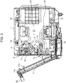
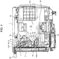
- FIG. 3 and FIG. 4 are cross-sectional views of heating cooker 50 according to the embodiment of the present disclosure, as viewed from the side.
- FIG. 3 illustrates a state during the closing operation of door 3
- FIG. 4 illustrates a closed state in which heating chamber opening 2a on the front surface of heating chamber 2 of cooker body 1 is closed by the closing operation of door 3.
- abutment end 14a of damper unit 5 projects in a substantially horizontal direction as viewed from the side so as to come into contact with the inner surface of door 3 during the closing operation of door 3.
- Abutment end 14a is configured to attenuate a rotating force of door 3 in the rotating direction during the closing operation of door 3 after coming into contact with the inner wall surface of door 3.
- abutment end 14a of damper unit 5 is pressed by the inner wall surface of door 3 and is stored inside damper opening 10a.
- projection ends 11a and 11b of door 3 are also in contact with detector 6 of the control system and detector 7 of the electric power system in latch switch unit 8, respectively, and thus the circuits corresponding to the detectors respectively are in an activatable state.
- damper unit 5 is provided in the casing of cooker body 1 and in addition to latch switch unit 8, various components such as the electric circuit of the control system and the electric circuit of the electric power system, magnetron 16 which is a microwave generator for generating a microwave, fan 17 (see FIG. 7 ) which is a cooler for cooling magnetron 16, electronic components, or the like, and the like are disposed in the space on the right surface side as viewed from the front surface of heating chamber 2.
- a plurality of heaters 18 and 19 are provided at positions above and below the heating chamber 2, respectively.
- damper unit 5 latch switch unit 8 electric circuit, and fan 17, which are described above are attached to heat insulation plate 20 which is a heat insulation member provided via an air layer between the wall surface of heating chamber 2 and the components so that heat from the wall surface of heating chamber 2 is not directly transferred to the components.
- heat insulation plate 20 which is a heat insulation member provided via an air layer between the wall surface of heating chamber 2 and the components so that heat from the wall surface of heating chamber 2 is not directly transferred to the components.
- air flow from fan 17 which is a cooler flows to the electric circuit, damper unit 5, and latch switch unit 8 to cool the respective components after cooling magnetron 16.
- detector 6 of the control system in latch switch unit 8 projects in the door direction (front direction of heating chamber 2) from heating chamber outer edge portion 10 of heating chamber 2.
- projection end 11a is provided at a position corresponding to detector 6 of the control system.
- the arm portion of latch switch unit 8 is configured to rotate by detector 6 of the control system being pressed by projection end 11a provided on door 3.
- detector 7 of the electric power system in the latch switch unit 8 is formed in the heating chamber outer edge portion 10 of the heating chamber 2 and projection end 11b is provided at a position corresponding to the detector 7 of the electric power system in the door 3.
- the projection end 11b of door 3 is introduced into detector 7 of the electric power system, the switching mechanism of the electric circuit of the electric power system in latch switch unit 8 is switched, and the on/off control of the electric power system is performed.
- a microwave leakage prevention mechanism (not illustrated) is provided at a position facing heating chamber outer edge portion 10 of heating chamber 2 in the closed state of door 3.
- the microwave leakage mechanism prevents leakage of microwaves from the inside portion of heating chamber 2 from a position between heating chamber outer edge portion 10 and the inner wall surface of door 3.
- damper unit 5 This configuration of damper unit 5 will be described.
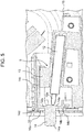
- FIG. 5 is a cross-sectional view illustrating a configuration of damper unit 5 according to the embodiment of the present disclosure.
- Damper unit 5 includes damper 12 that has impact absorption tip portion 12a that absorbs impact by contracting when damper unit 5 abuts on door 3, damper holder 13 that holds damper 12 and attaches damper 12 to heat insulation plate 20 (refer to FIG. 3 and FIG. 4 ) which is a heat insulation member, and damper cap 14 which is always pressed in a direction in which damper cap 14 is in contact with door 3 by impact absorption tip portion 12a of damper 12.
- Damper cap 14 has abutment end 14a which can be in contact with door 3 and projects from damper opening 10a of heating chamber outer edge portion 10 in the opened state of door 3, flange portion 14b that is formed to be radially expanded at the outer peripheral portion of the base of the projection portion of abutment end 14a, and slider 14c that slides along a linear groove formed on damper holder 13. Abutment end 14a, flange portion 14b and slider 14c are integrally formed in damper cap 14 by resin molding.
- slider 14c is configured to slide in a straight line shape along the groove formed in damper holder 13 along with the contraction operation of impact absorption tip portion 12a.
- flange portion tip 14d is formed at the outer peripheral end portion of flange portion 14b and flange portion tip 14d constitutes the position of the end portion on the front surface side of slider 14c.
- Pressing surface 14e is formed on a side opposite to abutment end 14a of damper cap 14 which is always pressed by impact absorption tip portion 12a of damper 12, and pressing surface 14e is formed on a position of a back surface side of the base of the projection portion of abutment end 14a, that is, on the rear surface side of flange portion 14b.
- Damper cap 14 configured as described above is configured to slide and move with respect to damper holder 13 in the front and rear direction of heating chamber 2 (actual pressing direction of abutment end 14a with respect to door 3). Damper holder 13 is positioned by abutting on positioning projection 15 formed on heat insulation plate 20. Accordingly, damper holder 13 is reliably attached to a predetermined position of heat insulation plate 20.
- Damper 12 used in damper unit 5 in the present embodiment is an oil damper and has a configuration in which impact absorption tip portion 12a moves in a contraction direction to attenuate the impact during the abutment.
- the configuration of the present disclosure is not limited to the oil damper, and as long as a damper has an impact absorption function by which the impact during the abutment between door 3 and abutment end 14a is absorbed and door 3 can be slowly and smoothly shifted to the closed state, the damper is appropriately used in consideration of the specification, shape, and the like thereof.
- damper cap 14 having abutment end 14a is always pressed by impact absorption tip portion 12a of damper 12 and is in contact with the inside surface of heating chamber outer edge portion 10 which is an outer peripheral portion of heating chamber opening 2a, in the opened state of door 3.
- flange portion tip 14d formed at the front surface side end portion of slider 14c of damper cap 14 is reliably in contact with the inner surface of heating chamber outer edge portion 10.
- damper opening 10a which is formed in heating chamber outer edge portion 10 and from which abutment end 14a of damper cap 14 projects is formed by an edge portion thereof being bent inward.
- Flange portion 14b is formed so as to radially expand from the base of the projection portion of abutment end 14a that can project from damper opening 10a and flange portion tip 14d that projects toward door 3 side is formed on an outer peripheral edge of flange portion 14b so as to surround heating chamber outer edge portion 10 (see FIG. 6D ).
- flange portion tip 14d projects in a direction of the inner surface of heating chamber outer edge portion 10 where damper opening 10a is formed, damper cap 14 is pressed by damper 12 and flange portion tip 14d is reliably in contact with the inner surface of heating chamber outer edge portion 10, in the opened state of door 3.
- damper opening 10a is closed by flange portion 14b. Therefore, moisture and foreign matter due to steam or the like from heating chamber 2 are prevented from penetrating into the inside of heating chamber outer edge portion 10 through damper opening 10a, and in particular, from penetrating into damper unit 5. Accordingly, since damper opening 10a is reliably closed by flange portion 14b, damper 12 that suppresses vibration is configured so that penetration of the oil and foreign matter such as dust in addition to moisture that has a fear that the function thereof may be degraded is reliably prevented, in the opened state of door 3.
- the projection direction of impact absorption tip portion 12a of damper 12 is an upward inclined direction as viewed from the side.
- pressing surface 14e of damper cap 14 that is always pressed by impact absorption tip portion 12a of damper 12 is formed on a surface orthogonal to the projecting direction of impact absorption tip portion 12a. Therefore, pressing surface 14e is a surface inclined in the pressing direction (substantially horizontal direction) of abutment end 14a, which is the front and rear direction of heating chamber 2 of damper cap 14. In other words, pressing surface 14e is formed in an inclined surface shape in the sliding direction of damper cap 14.
- pressing surface 14e of damper cap 14 which is always pressed by the impact absorption tip portion 12a is set to a surface orthogonal to the projecting direction of impact absorption tip portion 12a, and is set to a surface inclined in the pressing direction of abutment end 14a. Accordingly, the heating cooker is configured to be capable of increasing the tolerance of the disposition position of damper unit 5 in a state where the impact absorption capability of damper 12 is maintained. It is preferable that pressing surface 14e of damper cap 14 is provided at an inclined angle of about ⁇ 10 degrees in the pressing direction (substantially horizontal direction) of abutment end 14a.
- FIG. 6A to FIG. 6E are views illustrating a specific configuration of damper unit 5 in heating cooker 50 according to the embodiment of the present disclosure.
- FIG. 6A is a front view
- FIG. 6B is a top view
- FIG. 6C is a right side view thereof.
- FIG. 6D is a perspective view as viewed from the upper right side of the front surface side
- FIG. 6E is a perspective view as viewed the right side surface from the upper side of the rear surface side.
- damper 12, damper holder 13, and damper cap 14 are unitized and miniaturized in damper unit 5 and are configured to be capable of being easily attached to a desired position.
- damper unit 5 damper holder 13 attached to heat insulation plate 20 is disposed between damper 12 and heat insulation plate 20 and the side surface portion of damper 12 on a side opposite to heat insulation plate 20 is widely opened. Accordingly, a configuration in which heat transfer from heating chamber 2 is prevented can be realized and the heating cooker is configured to be reliably cooled by fan 17 (see FIG. 7 ) which is a cooler that forms air flow flowing along heat insulation plate 20 which is a heat insulation member.
- FIG. 7 is a view illustrating a cooling passage of the air flow from fan 17 which is a cooler in heating cooker 50 according to the embodiment of the present disclosure, as viewed from the right side.
- FIG. 7 illustrates a state in which the cover of the casing of cooker body 1 on the right side surface of heating cooker 50 is removed.
- fan 17 which is a cooler, is provided on the rear surface side of the right side surface as viewed from the front surface.
- the air flow blown out from fan 17 passes through a duct provided on the rear surface side and is blown out from a plurality of duct air outlets 17a to a desired cooling passage.
- the air flow from duct air outlet 17a mainly flows in the cooling passage in the direction indicated by the arrow.
- Magnetron 16 an electric circuit including electronic components connected to latch switch unit 8, heat insulation plate 20, and damper unit 5 are disposed on the cooling passage.
- heating cooker 50 of the present embodiment configured as described above, unpleasant sound and vibration generated during the closing operation of door 3 can be reliably reduced and even in a state where the disposition space and the disposition position are limited, easy action can be performed.
- the heating cooker 50 of the embodiment in the closed state of door 3, there is a configuration in which penetration of moisture or the like into the inside portion of the casing via damper opening 10a of abutment end 14a of damper unit 5 is prevented. Therefore, the heating cooker 50 of the embodiment has an excellent operability, high safety, high reliability, and a small size.
- the heating cooker since it is necessary to have a multifunctional high function and a small size and furthermore, there is a high heat region, there is a problem that the component disposition is greatly limited.
- the heating cooker of the present disclosure by providing a small-sized damper unit having a splash-proof and dust-proof effect and high placement tolerance with a simple configuration, a small-sized and highly reliable heating cooker can be configured.
- the heating cooker of the present disclosure unpleasant sound generated during the closing operation of the door can be reliably reduced, vibrations during the closing operation of the door can be suppressed, easy action with respect to the limitation of the disposition space and the disposition position can be performed and further, penetration of foreign matter into the inside portion of the casing can be prevented. Therefore, the heating cooker of the present disclosure is a small-sized heating cooker with high reliability, which has an operability by the user.
- the present disclosure configurations that can reduce unpleasant sound generated during the closing operation of the door, suppress vibrations during the closing operation of the door, and perform easy action with respect to the limitation of the disposition space and the disposition position are provided, and thus special effects that have excellent operability by the user and have high reliability are obtained. Therefore, since the present disclosure can be applied to various heating cookers including a microwave oven which is a microwave heating apparatus and a small-sized and highly reliable heating cooker can be provided on the market, the heating cooker of the present disclosure is useful.
Landscapes
- Engineering & Computer Science (AREA)
- Chemical & Material Sciences (AREA)
- Combustion & Propulsion (AREA)
- Mechanical Engineering (AREA)
- General Engineering & Computer Science (AREA)
- Electric Ovens (AREA)
Claims (4)
- Heizkocher, umfassend:eine Heizkammer (2);einen Kocherkörper (1), in dem sich die Heizkammer (2) befindet;eine Tür (3) des Kocherkörpers (1), wobei die Tür (3) einen Öffnungsvorgang und einen Schließvorgang im Hinblick auf eine Heizkammeröffnung (2a) durchführt, die an einer Vorderfläche der Heizkammer (2) bereitgestellt ist; undeine Dämpfereinheit (5), die an dem Kocherkörper (1) bereitgestellt ist und mit der Tür (3) in Kontakt kommt, bevor die Tür (3) während dem Schließvorgang der Tür (3) an den Kocherkörper (1) anstößt,wobei die Dämpfereinheit (5) Folgendes umfasst:einen Dämpfer (12), der einen Aufprallauffangspitzenabschnitt (12a) hat, der durch einen Aufprall zusammengezogen wird;dadurch gekennzeichnet, dass:eine Dämpferhalterung (13), die den Dämpfer (12) hält und an einem Hitzeisolationselement (20) angebracht ist, das über einen Abstand zwischen der Dämpferhalterung (13) und einer Wandfläche der Heizkammer (2) angeordnet ist;ein Dämpferdeckel (14), der immer in eine Richtung gedrückt ist, in der der Dämpferdeckel (14) durch den Aufprallauffangspitzenabschnitt (12a) an die Tür (3) anstößt, während dem Schließvorgang der Tür (3) an die Tür (3) anstößt und im Hinblick auf die Dämpferhalterung (13) gleitet, undeinen Aufprall während eines Anstoßens an die Tür (3) auf den Aufprallauffangspitzenabschnitt (12a) überträgt;wobei der Dämpferdeckel (14) Folgendes umfasst:ein Anstoßende (14a), das von einer Dämpferöffnung vorsteht, die in einem äußeren Kantenabschnitt der Heizkammer gebildet ist, der einen äußeren Umfangsabschnitt der Heizkammeröffnung (2a) darstellt, in einem geöffneten Zustand der Heizkammer (2);einen Flanschabschnitt (14b), der an einer Basis eines Vorstehabschnitts des Anstoßendes (14a) gebildet ist und sich radial erstreckt; undeinen Gleiter (14c), der mit der Dämpferhalterung (13) zusammen mit einem Zusammenziehvorgang des Aufprallauffangspitzenabschnitts (12a) gleitet, nachdem das Anstoßende (14a) an die Tür (3) angestoßen ist, während einem Schließvorgang der Tür (3), undwobei die Dämpferöffnung konfiguriert ist, um durch den Flanschabschnitt (14) dadurch, dass das Anstoßende (14a) vorsteht, verschlossen zu werden.
- Heizkocher nach Anspruch 1,
wobei ein Austrittsverhinderungselement (9) bereitgestellt ist, um die Heizkammeröffnung (2a) zwischen der Tür (3) und dem äußeren Kantenabschnitt der Heizkammer zu umgeben, im geschlossenen Zustand der Tür (3), und
wobei die Dämpferöffnung von der Vorderfläche aus gesehen außerhalb des Austrittsverhinderungselements (9) angeordnet ist im geschlossenen Zustand der Tür (3). - Heizkocher nach Anspruch 1 oder 2, ferner umfassend:eine Verriegelungsschaltereinheit (8), die einen Heizvorgang des Heizkochers mit dem Öffnungs- und Schließvorgang der Tür (3) koppelt,wobei die Verriegelungsschaltereinheit (8) so konfiguriert ist, dass ein Start des Heizvorgangs in einem startbaren Zustand ist nachdem ein Detektor (6, 7) der Verriegelungsschaltereinheit (8) und die Tür (3) miteinander in Kontakt kommen, und so konfiguriert ist, dass die Tür (3) und die Detektoren (6, 7) der Verriegelungsschaltereinheit (8) in einem Aufprallauffangzustand miteinander in Kontakt kommen, nachdem die Tür (3) und das Anstoßende bei dem Schließvorgang der Tür (3) aneinander gestoßen sind.
- Heizkocher nach einem der Ansprüche 1 bis 3,
wobei ein Kühler (17), der den Luftstrom kühlt, in dem Kocherkörper (1) angeordnet ist,
wobei der Dämpfer (12) von der Dämpferhalterung (13) so gehalten wird, dass mindestens ein Abschnitt des Dämpfers freiliegt (12), und
wobei der Dämpfer (12) an einem Kühlungskanal des Luftstroms durch den Kühler (17) angeordnet ist.
Applications Claiming Priority (2)
| Application Number | Priority Date | Filing Date | Title |
|---|---|---|---|
| JP2015108878A JP6481825B2 (ja) | 2015-05-28 | 2015-05-28 | 加熱調理器 |
| PCT/JP2016/002507 WO2016189859A1 (ja) | 2015-05-28 | 2016-05-24 | 加熱調理器 |
Publications (3)
| Publication Number | Publication Date |
|---|---|
| EP3306201A1 EP3306201A1 (de) | 2018-04-11 |
| EP3306201A4 EP3306201A4 (de) | 2018-05-30 |
| EP3306201B1 true EP3306201B1 (de) | 2019-12-25 |
Family
ID=57392700
Family Applications (1)
| Application Number | Title | Priority Date | Filing Date |
|---|---|---|---|
| EP16799572.9A Active EP3306201B1 (de) | 2015-05-28 | 2016-05-24 | Thermokocher |
Country Status (5)
| Country | Link |
|---|---|
| EP (1) | EP3306201B1 (de) |
| JP (1) | JP6481825B2 (de) |
| CN (1) | CN107614978B (de) |
| CA (1) | CA2984593C (de) |
| WO (1) | WO2016189859A1 (de) |
Families Citing this family (4)
| Publication number | Priority date | Publication date | Assignee | Title |
|---|---|---|---|---|
| KR102542543B1 (ko) | 2017-09-29 | 2023-06-14 | 삼성전자주식회사 | 가전기기 |
| CN109785507A (zh) * | 2019-04-02 | 2019-05-21 | 常州市龙星工业自动化系统有限公司 | 一种自动售货装置物品自动出货的方法及装置 |
| CN114687615B (zh) * | 2020-12-31 | 2023-07-21 | 广东美的厨房电器制造有限公司 | 烹饪设备 |
| JP7496500B2 (ja) * | 2021-05-31 | 2024-06-07 | パナソニックIpマネジメント株式会社 | 加熱調理器 |
Family Cites Families (9)
| Publication number | Priority date | Publication date | Assignee | Title |
|---|---|---|---|---|
| JPS584289A (ja) * | 1981-06-29 | 1983-01-11 | 松下電器産業株式会社 | 高周波加熱装置 |
| JP4337243B2 (ja) * | 2000-07-24 | 2009-09-30 | パナソニック株式会社 | 高周波加熱調理器 |
| JP2006226617A (ja) * | 2005-02-18 | 2006-08-31 | Hitachi Home & Life Solutions Inc | 加熱調理器 |
| DE102007029696A1 (de) * | 2007-06-27 | 2009-01-08 | BSH Bosch und Siemens Hausgeräte GmbH | Haushaltsgerät, insbesondere Backofen |
| DE102008018867A1 (de) * | 2008-04-15 | 2009-10-22 | BSH Bosch und Siemens Hausgeräte GmbH | Hausgerätvorrichtung |
| JP5633954B2 (ja) * | 2009-08-21 | 2014-12-03 | 株式会社ムラコシ精工 | 扉装置 |
| CN103670106A (zh) * | 2012-09-19 | 2014-03-26 | 天津通奥废旧物资回收有限公司 | 一种防撞条 |
| CN204060358U (zh) * | 2014-07-16 | 2014-12-31 | 中山市列武洁具有限公司 | 一种推拉门的减震静音结构 |
| CN204492408U (zh) * | 2014-12-31 | 2015-07-22 | 合肥义和汽车零部件有限公司 | 一种减震车门限位器 |
-
2015
- 2015-05-28 JP JP2015108878A patent/JP6481825B2/ja active Active
-
2016
- 2016-05-24 CN CN201680029054.8A patent/CN107614978B/zh active Active
- 2016-05-24 CA CA2984593A patent/CA2984593C/en active Active
- 2016-05-24 EP EP16799572.9A patent/EP3306201B1/de active Active
- 2016-05-24 WO PCT/JP2016/002507 patent/WO2016189859A1/ja not_active Ceased
Non-Patent Citations (1)
| Title |
|---|
| None * |
Also Published As
| Publication number | Publication date |
|---|---|
| CN107614978A (zh) | 2018-01-19 |
| CA2984593C (en) | 2019-05-21 |
| JP2016223661A (ja) | 2016-12-28 |
| CA2984593A1 (en) | 2016-12-01 |
| EP3306201A1 (de) | 2018-04-11 |
| EP3306201A4 (de) | 2018-05-30 |
| JP6481825B2 (ja) | 2019-03-13 |
| WO2016189859A1 (ja) | 2016-12-01 |
| CN107614978B (zh) | 2019-06-21 |
Similar Documents
| Publication | Publication Date | Title |
|---|---|---|
| EP3306201B1 (de) | Thermokocher | |
| JP5723955B2 (ja) | 調理装置 | |
| JP5723954B2 (ja) | 調理装置 | |
| KR102553477B1 (ko) | 조리기기 | |
| JP5723957B2 (ja) | 調理装置 | |
| US11971176B2 (en) | Cooking appliance | |
| US20140318389A1 (en) | Cooking apparatus | |
| US12042090B2 (en) | Cooking appliance | |
| KR102343085B1 (ko) | 조리 기기 | |
| ES3033481T3 (en) | Method for cooling the escaping vapour or steam from the cooking chamber of a cooking appliance and cooking appliance | |
| KR102683539B1 (ko) | 노브 어셈블리 및 이를 갖는 조리기기 | |
| KR102553498B1 (ko) | 조리기기 | |
| KR100377732B1 (ko) | 전자레인지의 댐퍼장치 | |
| KR100646879B1 (ko) | 전기오븐레인지의 오븐부 구조 | |
| JP2010286121A (ja) | 卓上タイプの加熱調理器 | |
| TR201610863A2 (tr) | Havalandirmasi ve buhar çekme özelli̇ği̇ i̇yi̇leşti̇ri̇len firin | |
| JP5542563B2 (ja) | 加熱調理器 | |
| KR100646878B1 (ko) | 전기오븐레인지의 컨벡션부 구조 | |
| JP5219070B2 (ja) | 衣類プレス器 | |
| KR101121915B1 (ko) | 전기오븐레인지의 탑버너부 | |
| CN114427691A (zh) | 烹饪器具 | |
| KR20060036997A (ko) | 전기오븐레인지 | |
| JPH0610707U (ja) | オーブン電子レンジ | |
| JP2009189516A (ja) | 衣類プレス器 | |
| KR20120073600A (ko) | 전자레인지 |
Legal Events
| Date | Code | Title | Description |
|---|---|---|---|
| STAA | Information on the status of an ep patent application or granted ep patent |
Free format text: STATUS: THE INTERNATIONAL PUBLICATION HAS BEEN MADE |
|
| PUAI | Public reference made under article 153(3) epc to a published international application that has entered the european phase |
Free format text: ORIGINAL CODE: 0009012 |
|
| STAA | Information on the status of an ep patent application or granted ep patent |
Free format text: STATUS: REQUEST FOR EXAMINATION WAS MADE |
|
| 17P | Request for examination filed |
Effective date: 20171018 |
|
| AK | Designated contracting states |
Kind code of ref document: A1 Designated state(s): AL AT BE BG CH CY CZ DE DK EE ES FI FR GB GR HR HU IE IS IT LI LT LU LV MC MK MT NL NO PL PT RO RS SE SI SK SM TR |
|
| AX | Request for extension of the european patent |
Extension state: BA ME |
|
| A4 | Supplementary search report drawn up and despatched |
Effective date: 20180504 |
|
| RIC1 | Information provided on ipc code assigned before grant |
Ipc: E05F 5/02 20060101ALI20180426BHEP Ipc: F24C 15/02 20060101ALI20180426BHEP Ipc: F24C 7/02 20060101AFI20180426BHEP |
|
| DAV | Request for validation of the european patent (deleted) | ||
| DAX | Request for extension of the european patent (deleted) | ||
| REG | Reference to a national code |
Ref country code: DE Ref legal event code: R079 Ref document number: 602016027000 Country of ref document: DE Free format text: PREVIOUS MAIN CLASS: F24C0007020000 Ipc: E05F0005100000 |
|
| GRAP | Despatch of communication of intention to grant a patent |
Free format text: ORIGINAL CODE: EPIDOSNIGR1 |
|
| STAA | Information on the status of an ep patent application or granted ep patent |
Free format text: STATUS: GRANT OF PATENT IS INTENDED |
|
| RIC1 | Information provided on ipc code assigned before grant |
Ipc: E05F 5/02 20060101ALI20190820BHEP Ipc: E05F 5/10 20060101AFI20190820BHEP Ipc: F24C 15/02 20060101ALI20190820BHEP |
|
| INTG | Intention to grant announced |
Effective date: 20190911 |
|
| GRAS | Grant fee paid |
Free format text: ORIGINAL CODE: EPIDOSNIGR3 |
|
| GRAA | (expected) grant |
Free format text: ORIGINAL CODE: 0009210 |
|
| STAA | Information on the status of an ep patent application or granted ep patent |
Free format text: STATUS: THE PATENT HAS BEEN GRANTED |
|
| AK | Designated contracting states |
Kind code of ref document: B1 Designated state(s): AL AT BE BG CH CY CZ DE DK EE ES FI FR GB GR HR HU IE IS IT LI LT LU LV MC MK MT NL NO PL PT RO RS SE SI SK SM TR |
|
| REG | Reference to a national code |
Ref country code: GB Ref legal event code: FG4D |
|
| REG | Reference to a national code |
Ref country code: CH Ref legal event code: EP |
|
| REG | Reference to a national code |
Ref country code: DE Ref legal event code: R096 Ref document number: 602016027000 Country of ref document: DE |
|
| REG | Reference to a national code |
Ref country code: AT Ref legal event code: REF Ref document number: 1217300 Country of ref document: AT Kind code of ref document: T Effective date: 20200115 |
|
| REG | Reference to a national code |
Ref country code: IE Ref legal event code: FG4D |
|
| REG | Reference to a national code |
Ref country code: NL Ref legal event code: MP Effective date: 20191225 |
|
| PG25 | Lapsed in a contracting state [announced via postgrant information from national office to epo] |
Ref country code: LT Free format text: LAPSE BECAUSE OF FAILURE TO SUBMIT A TRANSLATION OF THE DESCRIPTION OR TO PAY THE FEE WITHIN THE PRESCRIBED TIME-LIMIT Effective date: 20191225 Ref country code: GR Free format text: LAPSE BECAUSE OF FAILURE TO SUBMIT A TRANSLATION OF THE DESCRIPTION OR TO PAY THE FEE WITHIN THE PRESCRIBED TIME-LIMIT Effective date: 20200326 Ref country code: SE Free format text: LAPSE BECAUSE OF FAILURE TO SUBMIT A TRANSLATION OF THE DESCRIPTION OR TO PAY THE FEE WITHIN THE PRESCRIBED TIME-LIMIT Effective date: 20191225 Ref country code: NO Free format text: LAPSE BECAUSE OF FAILURE TO SUBMIT A TRANSLATION OF THE DESCRIPTION OR TO PAY THE FEE WITHIN THE PRESCRIBED TIME-LIMIT Effective date: 20200325 Ref country code: LV Free format text: LAPSE BECAUSE OF FAILURE TO SUBMIT A TRANSLATION OF THE DESCRIPTION OR TO PAY THE FEE WITHIN THE PRESCRIBED TIME-LIMIT Effective date: 20191225 Ref country code: BG Free format text: LAPSE BECAUSE OF FAILURE TO SUBMIT A TRANSLATION OF THE DESCRIPTION OR TO PAY THE FEE WITHIN THE PRESCRIBED TIME-LIMIT Effective date: 20200325 Ref country code: FI Free format text: LAPSE BECAUSE OF FAILURE TO SUBMIT A TRANSLATION OF THE DESCRIPTION OR TO PAY THE FEE WITHIN THE PRESCRIBED TIME-LIMIT Effective date: 20191225 |
|
| REG | Reference to a national code |
Ref country code: LT Ref legal event code: MG4D |
|
| PG25 | Lapsed in a contracting state [announced via postgrant information from national office to epo] |
Ref country code: RS Free format text: LAPSE BECAUSE OF FAILURE TO SUBMIT A TRANSLATION OF THE DESCRIPTION OR TO PAY THE FEE WITHIN THE PRESCRIBED TIME-LIMIT Effective date: 20191225 Ref country code: HR Free format text: LAPSE BECAUSE OF FAILURE TO SUBMIT A TRANSLATION OF THE DESCRIPTION OR TO PAY THE FEE WITHIN THE PRESCRIBED TIME-LIMIT Effective date: 20191225 |
|
| PG25 | Lapsed in a contracting state [announced via postgrant information from national office to epo] |
Ref country code: AL Free format text: LAPSE BECAUSE OF FAILURE TO SUBMIT A TRANSLATION OF THE DESCRIPTION OR TO PAY THE FEE WITHIN THE PRESCRIBED TIME-LIMIT Effective date: 20191225 |
|
| PG25 | Lapsed in a contracting state [announced via postgrant information from national office to epo] |
Ref country code: EE Free format text: LAPSE BECAUSE OF FAILURE TO SUBMIT A TRANSLATION OF THE DESCRIPTION OR TO PAY THE FEE WITHIN THE PRESCRIBED TIME-LIMIT Effective date: 20191225 Ref country code: CZ Free format text: LAPSE BECAUSE OF FAILURE TO SUBMIT A TRANSLATION OF THE DESCRIPTION OR TO PAY THE FEE WITHIN THE PRESCRIBED TIME-LIMIT Effective date: 20191225 Ref country code: NL Free format text: LAPSE BECAUSE OF FAILURE TO SUBMIT A TRANSLATION OF THE DESCRIPTION OR TO PAY THE FEE WITHIN THE PRESCRIBED TIME-LIMIT Effective date: 20191225 Ref country code: PT Free format text: LAPSE BECAUSE OF FAILURE TO SUBMIT A TRANSLATION OF THE DESCRIPTION OR TO PAY THE FEE WITHIN THE PRESCRIBED TIME-LIMIT Effective date: 20200520 Ref country code: RO Free format text: LAPSE BECAUSE OF FAILURE TO SUBMIT A TRANSLATION OF THE DESCRIPTION OR TO PAY THE FEE WITHIN THE PRESCRIBED TIME-LIMIT Effective date: 20191225 |
|
| PG25 | Lapsed in a contracting state [announced via postgrant information from national office to epo] |
Ref country code: SM Free format text: LAPSE BECAUSE OF FAILURE TO SUBMIT A TRANSLATION OF THE DESCRIPTION OR TO PAY THE FEE WITHIN THE PRESCRIBED TIME-LIMIT Effective date: 20191225 Ref country code: SK Free format text: LAPSE BECAUSE OF FAILURE TO SUBMIT A TRANSLATION OF THE DESCRIPTION OR TO PAY THE FEE WITHIN THE PRESCRIBED TIME-LIMIT Effective date: 20191225 Ref country code: IS Free format text: LAPSE BECAUSE OF FAILURE TO SUBMIT A TRANSLATION OF THE DESCRIPTION OR TO PAY THE FEE WITHIN THE PRESCRIBED TIME-LIMIT Effective date: 20200425 |
|
| REG | Reference to a national code |
Ref country code: DE Ref legal event code: R097 Ref document number: 602016027000 Country of ref document: DE |
|
| PG25 | Lapsed in a contracting state [announced via postgrant information from national office to epo] |
Ref country code: ES Free format text: LAPSE BECAUSE OF FAILURE TO SUBMIT A TRANSLATION OF THE DESCRIPTION OR TO PAY THE FEE WITHIN THE PRESCRIBED TIME-LIMIT Effective date: 20191225 Ref country code: DK Free format text: LAPSE BECAUSE OF FAILURE TO SUBMIT A TRANSLATION OF THE DESCRIPTION OR TO PAY THE FEE WITHIN THE PRESCRIBED TIME-LIMIT Effective date: 20191225 |
|
| PLBE | No opposition filed within time limit |
Free format text: ORIGINAL CODE: 0009261 |
|
| STAA | Information on the status of an ep patent application or granted ep patent |
Free format text: STATUS: NO OPPOSITION FILED WITHIN TIME LIMIT |
|
| REG | Reference to a national code |
Ref country code: AT Ref legal event code: MK05 Ref document number: 1217300 Country of ref document: AT Kind code of ref document: T Effective date: 20191225 |
|
| PG25 | Lapsed in a contracting state [announced via postgrant information from national office to epo] |
Ref country code: SI Free format text: LAPSE BECAUSE OF FAILURE TO SUBMIT A TRANSLATION OF THE DESCRIPTION OR TO PAY THE FEE WITHIN THE PRESCRIBED TIME-LIMIT Effective date: 20191225 |
|
| 26N | No opposition filed |
Effective date: 20200928 |
|
| PG25 | Lapsed in a contracting state [announced via postgrant information from national office to epo] |
Ref country code: AT Free format text: LAPSE BECAUSE OF FAILURE TO SUBMIT A TRANSLATION OF THE DESCRIPTION OR TO PAY THE FEE WITHIN THE PRESCRIBED TIME-LIMIT Effective date: 20191225 Ref country code: MC Free format text: LAPSE BECAUSE OF FAILURE TO SUBMIT A TRANSLATION OF THE DESCRIPTION OR TO PAY THE FEE WITHIN THE PRESCRIBED TIME-LIMIT Effective date: 20191225 Ref country code: CH Free format text: LAPSE BECAUSE OF NON-PAYMENT OF DUE FEES Effective date: 20200531 Ref country code: IT Free format text: LAPSE BECAUSE OF FAILURE TO SUBMIT A TRANSLATION OF THE DESCRIPTION OR TO PAY THE FEE WITHIN THE PRESCRIBED TIME-LIMIT Effective date: 20191225 Ref country code: LI Free format text: LAPSE BECAUSE OF NON-PAYMENT OF DUE FEES Effective date: 20200531 |
|
| PG25 | Lapsed in a contracting state [announced via postgrant information from national office to epo] |
Ref country code: PL Free format text: LAPSE BECAUSE OF FAILURE TO SUBMIT A TRANSLATION OF THE DESCRIPTION OR TO PAY THE FEE WITHIN THE PRESCRIBED TIME-LIMIT Effective date: 20191225 |
|
| REG | Reference to a national code |
Ref country code: BE Ref legal event code: MM Effective date: 20200531 |
|
| GBPC | Gb: european patent ceased through non-payment of renewal fee |
Effective date: 20200524 |
|
| PG25 | Lapsed in a contracting state [announced via postgrant information from national office to epo] |
Ref country code: LU Free format text: LAPSE BECAUSE OF NON-PAYMENT OF DUE FEES Effective date: 20200524 |
|
| PG25 | Lapsed in a contracting state [announced via postgrant information from national office to epo] |
Ref country code: FR Free format text: LAPSE BECAUSE OF NON-PAYMENT OF DUE FEES Effective date: 20200531 Ref country code: GB Free format text: LAPSE BECAUSE OF NON-PAYMENT OF DUE FEES Effective date: 20200524 Ref country code: IE Free format text: LAPSE BECAUSE OF NON-PAYMENT OF DUE FEES Effective date: 20200524 |
|
| PG25 | Lapsed in a contracting state [announced via postgrant information from national office to epo] |
Ref country code: BE Free format text: LAPSE BECAUSE OF NON-PAYMENT OF DUE FEES Effective date: 20200531 |
|
| PG25 | Lapsed in a contracting state [announced via postgrant information from national office to epo] |
Ref country code: TR Free format text: LAPSE BECAUSE OF FAILURE TO SUBMIT A TRANSLATION OF THE DESCRIPTION OR TO PAY THE FEE WITHIN THE PRESCRIBED TIME-LIMIT Effective date: 20191225 Ref country code: MT Free format text: LAPSE BECAUSE OF FAILURE TO SUBMIT A TRANSLATION OF THE DESCRIPTION OR TO PAY THE FEE WITHIN THE PRESCRIBED TIME-LIMIT Effective date: 20191225 Ref country code: CY Free format text: LAPSE BECAUSE OF FAILURE TO SUBMIT A TRANSLATION OF THE DESCRIPTION OR TO PAY THE FEE WITHIN THE PRESCRIBED TIME-LIMIT Effective date: 20191225 |
|
| PG25 | Lapsed in a contracting state [announced via postgrant information from national office to epo] |
Ref country code: MK Free format text: LAPSE BECAUSE OF FAILURE TO SUBMIT A TRANSLATION OF THE DESCRIPTION OR TO PAY THE FEE WITHIN THE PRESCRIBED TIME-LIMIT Effective date: 20191225 |
|
| PGFP | Annual fee paid to national office [announced via postgrant information from national office to epo] |
Ref country code: DE Payment date: 20250521 Year of fee payment: 10 |