EP3306166B1 - Verbindungssystem für schlauchleitungen mit einer hebelarmkupplung - Google Patents
Verbindungssystem für schlauchleitungen mit einer hebelarmkupplung Download PDFInfo
- Publication number
- EP3306166B1 EP3306166B1 EP17194357.4A EP17194357A EP3306166B1 EP 3306166 B1 EP3306166 B1 EP 3306166B1 EP 17194357 A EP17194357 A EP 17194357A EP 3306166 B1 EP3306166 B1 EP 3306166B1
- Authority
- EP
- European Patent Office
- Prior art keywords
- coupling
- lever arm
- sealing ring
- male
- intermediate position
- Prior art date
- Legal status (The legal status is an assumption and is not a legal conclusion. Google has not performed a legal analysis and makes no representation as to the accuracy of the status listed.)
- Active
Links
Images







Classifications
-
- F—MECHANICAL ENGINEERING; LIGHTING; HEATING; WEAPONS; BLASTING
- F16—ENGINEERING ELEMENTS AND UNITS; GENERAL MEASURES FOR PRODUCING AND MAINTAINING EFFECTIVE FUNCTIONING OF MACHINES OR INSTALLATIONS; THERMAL INSULATION IN GENERAL
- F16L—PIPES; JOINTS OR FITTINGS FOR PIPES; SUPPORTS FOR PIPES, CABLES OR PROTECTIVE TUBING; MEANS FOR THERMAL INSULATION IN GENERAL
- F16L37/00—Couplings of the quick-acting type
- F16L37/08—Couplings of the quick-acting type in which the connection between abutting or axially overlapping ends is maintained by locking members
- F16L37/12—Couplings of the quick-acting type in which the connection between abutting or axially overlapping ends is maintained by locking members using hooks, pawls, or other movable or insertable locking members
- F16L37/18—Joints tightened by eccentrics or rotatable cams
Definitions
- the present invention relates to a connection system for hose lines with a lever arm coupling.
- Lever arm couplings for the detachable connection of hose lines in which liquids, solids and gases are transported are well known in the prior art.
- These lever arm couplings consist of a male coupling and a female coupling, which are connected to a first or second hose line or an end plug.
- the mother coupling has a receiving housing with a receiving area into which the male coupling fits.
- the mother coupling is usually provided with two lever arms for attaching the male coupling to the receiving housing, which are on opposite sides of the receiving housing are arranged and are pivotable between a closed and an open position.
- a pressure section of the lever arm engages through a radial opening in the receiving area of the receiving housing.
- the male coupling has a corresponding circumferential groove, in which the pressing section of the lever arms engages with a pressing surface.
- the pressure section of the lever arm does not engage in the receiving housing, so that the male coupling can be freely moved in and out of the receiving housing.
- lever arm couplings have an eccentric lever with a rounded pressure section, so that the pressure surface is moved into and out of the receiving area by rotating the lever arm.
- the pressure surface of the lever arm engages in the circumferential groove of the male coupling and drives the male coupling into the receiving housing until it abuts a sealing ring and is in tight connection with the female coupling.
- the pressure section of the lever arm is withdrawn from the receiving area during decoupling and the father coupling is driven backwards until it is completely decoupled and can be completely pulled out of the mother coupling. If the hose lines are under pressure there is a risk of decoupling that the pressure suddenly escapes in an uncontrolled manner as soon as the seal is free.
- lever arm coupling the lever arms of which cannot be actuated when the hose line is under pressure.
- the lever arm coupling is provided with a cylinder in which a piston can be moved depending on the pressure in the hose line.
- the piston is connected to a bolt which locks a lever arm when the hose line is under pressure and releases it when the hose line is not under pressure.
- a lever arm coupling with a two-stage decoupling process is introduced so that the father coupling is not immediately released when decoupled under pressure and flung directly out of the mother coupling.
- the pressure surface of the lever arm was additionally provided with a cam. If the lever arm is rotated to decouple the coupling parts, the coupling parts are slightly moved apart in a first stage and moved towards each other again in a second stage before they are completely decoupled. In the second stage of the decoupling process, the coupling parts move against the pressure direction. This would be under high pressure it takes tremendous force to open the lever arm completely, so that the lever arm coupling is blocked in this first intermediate position, so to speak. For safety reasons, the decoupling of the hose lines is impossible. The operator who wants to decouple the lever arm coupling must therefore first reduce the pressure in the hose lines before he can open the coupling completely.
- the present invention has as its object to improve a system of the type mentioned in such a way that the advantages of the known connection systems for hose lines with a lever arm coupling are retained, the system consists of a father coupling, a mother coupling, two lever arms and a sealing ring, the lever arms remain in the closed position in the event of vibrations, block the lever arms in an intermediate position when opening under pressure and in this intermediate position the overpressure can gradually and controlledly escape from the hose system via the sealing ring.
- This object is achieved by a connection system for hose lines with a lever arm coupling with the features of claim 1.
- the relative sizes of these thicknesses a, b, c and d are as follows: a>c>b> d.
- the pressure section 3a thus engages more or less deeply through the radial engagement opening 22 in the receiving area 21 of the mother coupling 2 ( Figures 3-5 ).
- the pressure section 3a has a thickness d from the axis of rotation 34 and in the direction of the receiving region 21. According to the invention, this thickness d is sufficiently small so that the pressure section 3 a does not engage in the receiving housing 21 and the male coupling 1 can be freely inserted and carried out in the female coupling 2.
- the male coupling 1 is inserted into the receiving area 21 of the female coupling and the lever arms 3 are pivoted from the open position to the closed position (FIG 3).
- the pressing section 3a has a thickness a from the axis of rotation 34 and in the direction of the receiving region 21.
- the pressure surface 32 engages in the corresponding circumferential groove 11 of the male coupling, whereby the male coupling is firmly and securely anchored in the receiving area 21 of the female coupling. It is important for the tightness of the connection between the coupling parts 1-2 that the male coupling 1 not only slightly abuts the sealing ring 4 in the closed position, but presses it against the female coupling 2.
- the decoupling of the lever arm coupling is carried out according to a two-stage process.
- the lever arms 3 are from the closed position of the Figure 3 to the intermediate position of the Figure 4 pivoted.
- the pressing section 3a has a thickness b from the axis of rotation 34 and in the direction of the receiving region 21. Since the thickness b is smaller than the thickness a of the closed position, the grip loosens around the circumferential groove 11 of the male coupling 1, so that the coupling parts 1-2 move apart slightly. If the hose lines are under pressure, this movement apart occurs spontaneously until the male coupling 1 of the projecting cam 31 is in the intermediate position Figure 4 is blocked.
- the lever arms 3 are further from the intermediate position Figure 4 to the position of the Figure 5 turned around.
- the pressure section 3a points from the axis of rotation 34 and in the direction of the Recording area 21 a thickness c. Since the distance c is greater than the distance b of the intermediate position, the coupling parts 1-2 are pushed slightly towards each other again ( Figure 5 ) before they are completely decoupled in the subsequent open position ( Figure 6 ).
- the first stage of the decoupling process is effortless because the pressure drives the coupling parts 1-2 apart.
- the coupling parts 1-2 are moved towards each other again, ie counter to the pressure direction.
- a deflection of the lever arms 3 and the coupling parts 1-2 from the intermediate position of the Figure 4 is therefore excluded since each movement of the lever arms 3 entails a deeper engagement of the pressure surface 32 or of the cam 31 in the receiving area 21 and the coupling parts 1-2 are moved against the pressure force.
- the coupling parts 1-2 are pressed apart so violently that an operator can only pull them apart with great force using the lever arms 3. In the intermediate position, the lever arm coupling is blocked.
- the invention provides for the excess pressure to escape from the hose system in the intermediate position via the sealing ring 4.
- the connection between the mother and father coupling is made leaky, ie that a passage is made possible which allows the excess pressure between the sealing ring 4 and the coupling parts 1-2 to escape.
- sealing rings 4 with a square or rectangular profile are used, which in the closed position have the largest possible contact surface with the coupling parts 1-2 and thus ensure a good seal of the connection ( Figure 7a ).
- the coupling parts 1-2 are moved apart from the closed position to the intermediate position, the compressed sealing ring 4 expands ( Figure 7b ).
- the sealing ring 4 with a square or rectangular profile expands laterally evenly and the contact surface with both coupling parts 1-2 remains the same. Despite the movement of the coupling parts away from each other, the connection remains tight as in the closed position until the sealing ring 4 regains its original shape, separates from the coupling parts 1-2 and the connection suddenly becomes completely leaky ( Figure 7c ).
- the overpressure is to escape gradually and in a controlled manner from the hose system via the sealing ring. This is achieved in that the sealing ring 4 and the male coupling 1 are not suddenly separated. Rather, the contact area between the sealing ring 4 and the male coupling 1 is gradually reduced, so that the tightness of the connection gradually decreases and the excess pressure can gradually escape.
- sealing rings 4 with a larger diameter than the standard sealing ring with a rectangular profile should preferably be used, which are then compressed and deformed more strongly between the two coupling parts 1-2.
- a modification of the male coupling 1 is undesirable since the male coupling is a standardized standard component. Therefore, it is provided according to the invention to improve the design of the lever arm or arms 3 of the mother clutch 2, which control the father clutch 1 directly. These can be replaced on an existing standard coupling with relatively little effort.
- the lever arm 3 is adapted in such a way that a cam 31, as is known from the prior art, of the lever arm 3 is rounded off, so that the cam 31 has a curved but tapering shape and is not angular from the pressure section 3a of the lever arm 3 protrudes ( Figure 8 ).
- the expression “lever arm 3 with curved cams 31” is to be understood as a lever arm 3, the pressure surface 3a of the lever arm 3 always being tangentially in contact with the male coupling between the closed position and the intermediate position.
- Conventional angular cams 31 cause the coupling parts 1-2 to be thrown abruptly and away from one another with great force.
- the sealing ring 4 comprises a core 41 made of elastic material ( Figure 1e ) such as rubber or caoutchouc, for example made of Viton®.
- the elastic core material 41 is used so that the sealing ring 4 can be strongly compressed so that it is strongly deformed in the closed position between the coupling parts 1-2 and the connection surface to the coupling parts is as large as possible, so that a tight connection is created.
- elastic materials such as rubber usually have a high coefficient of friction and therefore adhere to the coupling parts 1-2. There is therefore still the risk that such sealing rings 4 will stick to the male coupling 1 during the movement of the coupling parts 1-2 away from one another and only come loose suddenly and intermittently, which in turn can lead to blows.
- a sealing ring 4 with a round profile can rotate, so that the elasticity becomes irregular, or the ring can even be moved away from the desired position. In order to allow the excess pressure to escape in a controlled manner, it therefore makes sense if the seal ring's adhesion is reduced.
- a particularly advantageous embodiment variant therefore provides that the core 41 of the sealing ring 4 is surrounded by a sleeve 42 made of a second material which is less adhesive and has a low coefficient of friction.
- a sleeve 42 made of a second material which is less adhesive and has a low coefficient of friction.
- non-porous PTFE Teflon
- PTFE fulfills these criteria and also has excellent chemical inertness. This has the additional advantage that the sealing ring does not, or only slightly, wear even with highly reactive media which are conveyed through the hose lines and has a long service life.
- the sleeve 42 is wrapped around the sealing ring 4 and glued ( Figure 9a ). On one side of the sealing ring 4, both ends of the sleeve 42 are glued or welded together seamlessly.
- PTFE non-stick effect of PTFE
- connection between the two ends of the casing 42 is reinforced with an intermediate connecting layer 44 ( Figure 9b ).
- This connection layer 44 can consist of perfluoroalkoxy alkane (PFA), for example.
- the sealing ring Since the sealing ring is made of a material that is not very adhesive and because of the round profile it does not fit exactly into the recess in the nut coupling, it can slip under certain circumstances or not lie at the same distance from the outer edge over the entire circumference, which has a negative influence on the seal may have. It is therefore provided in a further embodiment that the sealing ring has a radial spacer 43 so that it is centered at the correct and above all even distance from the side walls of the nut coupling ( Figures 2-6 ).
- This spacer 43 can, for example, be a projecting part of the casing 42 ( Figures 9a-b ).
- the glued part of the sleeve 42 can simultaneously form the spacer 43.
Landscapes
- Engineering & Computer Science (AREA)
- General Engineering & Computer Science (AREA)
- Mechanical Engineering (AREA)
- Quick-Acting Or Multi-Walled Pipe Joints (AREA)
Description
- Die vorliegende Erfindung betrifft ein Verbindungssystem für Schlauchleitungen mit einer Hebelarmkupplung. Hebelarmkupplungen zur lösbaren Verbindung von Schlauchleitungen, in welchen Flüssigkeiten, Feststoffe und Gase befördert werden, sind im Stand der Technik bestens bekannt. Diese Hebelarmkupplungen bestehen aus einer Vaterkupplung und einer Mutterkupplung, welche mit einer ersten bzw. zweiten Schlauchleitung oder einem Endstopfen verbunden sind. Die Mutterkupplung weist ein Aufnahmegehäuse mit einem Aufnahmebereich auf, in den die Vaterkupplung hineinpasst. Zur Befestigung der Vaterkupplung am Aufnahmegehäuse ist die Mutterkupplung meistens mit zwei Hebelarmen versehen, welche auf gegenüberliegenden Seiten des Aufnahmegehäuses angeordnet sind und zwischen einer geschlossenen und einer offenen Position schwenkbar sind. In der geschlossenen Position greift ein Andruckabschnitt des Hebelarms durch eine radiale Öffnung im Aufnahmebereich des Aufnahmegehäuses ein. Die Vaterkupplung weist eine entsprechende Umfangsnut auf, in die der Andruckabschnitt der Hebelarme mit einer Andruckfläche klemmend eingreift. In der offenen Position greift der Andruckabschnitt des Hebelarms im Aufnahmegehäuse nicht ein, so dass die Vaterkupplung vom Aufnahmegehäuse frei ein- und ausgefahren werden kann. Durch diese Anordnung ergibt sich ein wirksamer Mechanismus zum schnellen und sicheren Koppeln und Entkoppeln von Schlauchleitungen, wie beispielsweise im Dokument
DE 297 07 747 U1 beschrieben und in der europäischen Norm EN-14420-7 definiert. - Herkömmliche Hebelarmkupplungen weisen einen Exzenterhebel mit abgerundeten Andruckabschnitt auf, sodass die Andruckfläche durch Drehung des Hebelarms in den Aufnahmebereich hinein bzw. hinaus bewegt wird. Bei der Drehung der Hebelarme zur Kopplung der Schlauchleitungen greift die Andruckfläche des Hebelarms in die Umfangsnut der Vaterkupplung ein und treibt die Vaterkupplung ins Aufnahmegehäuse herein, bis sie an einen Dichtring anstoßt und in dichter Verbindung mit der Mutterkupplung steht. Umgekehrt wird der Andruckabschnitt des Hebelarms bei der Entkopplung aus dem Aufnahmebereich zurückgezogen und die Vaterkupplung rückwärts getrieben, bis diese komplett entkoppelt wird und aus der Mutterkupplung vollständig herausgezogen werden kann. Falls die Schlauchleitungen unter Druck stehen, besteht bei der Entkopplung allerdings die Gefahr, dass der Druck unkontrolliert plötzlich entweicht, sobald die Dichtung frei ist. Die Hebelarme und/oder die Schlauchleitungen können dann abrupt zurückschlagen und es können Schäden entstehen oder sogar Personen verletzt werden.
Zur Lösung dieses Problems wurde in derUS 8,123,256 eine Hebelarmkupplung vorgestellt, deren Hebelarme nicht betätigt werden können, wenn die Schlauchleitung unter Druck steht. Dafür ist die Hebelarmkupplung mit einem Zylinder versehen, in welchem ein Kolben abhängig vom Druck in der Schlauchleitung bewegbar ist. Der Kolben ist mit einem Riegel verbunden, welcher einen Hebelarm verriegelt, wenn die Schlauchleitung unter Druck steht, und diesen freigibt, wenn die Schlauchleitung nicht unter Druck steht. In derUS 4,519,635 wird eine Hebelarmkupplung mit einem zweistufigem Entkopplungsvorgang vorgestellt, damit die Vaterkupplung beim Entkoppeln unter Druck nicht sofort freigegeben und direkt aus der Mutterkupplung hinausgeschleudert wird. Dafür wurde die Andruckfläche des Hebelarms zusätzlich mit einem Nocken versehen. Wenn der Hebelarm zur Entkopplung der Kupplungsteile gedreht wird, werden die Kupplungsteile in einer ersten Stufe leicht auseinander und in einer zweiten Stufe wieder leicht aufeinander zu bewegt, bevor sie vollständig entkoppelt werden. In der zweiten Stufe des Entkopplungsvorgangs erfolgt also die Bewegung der Kupplungsteile gegen die Druckrichtung. Dies würde bei hohem Druck eine ungeheure Kraft in Anspruch nehmen, um den Hebelarm komplett zu öffnen, sodass die Hebelarmkupplung in dieser ersten Zwischenposition sozusagen blockiert ist. Zur Sicherheit ist also die Entkopplung der Schlauchleitungen unmöglich. Der Bediener, der die Hebelarmkupplung entkoppeln möchte, muss also den Druck in den Schlauchleitungen also zuerst senken bevor er die Kupplung komplett öffnen kann. Da die Kupplung in dieser geschlossenen Position immer noch Dicht ist, muss zuerst an einem anderen Punkt der Leitung der Druck abgelassen werden. In derWO 2009/156357 A1 wird eine weitere Hebelarmkupplung beschrieben, welche eine kontrollierte Druckentlastung während des Entkopplungsvorgangs bei mit Druck beaufschlagter Verbindung zwischen zwei Schlauchleitungen gewährleistet. Dafür ist neben jedem Hebelarm zusätzlich eine Sicherungsscheibe angeordnet, womit die Vaterkupplung in einer gesicherten Druckentlastungsposition relativ zur Mutterkupplung klemmend fixierbar ist. Zur Lösung wird bei dieser Vorrichtung eine Sicherungsscheibe mit einer komplexen Geometrie eingesetzt. Dadurch dass diese Sicherungsscheibe ein zusätzliches bewegliches Teil ist, welche am Aufnahmegehäuse der Mutterkupplung angeordnet ist und mit der Vaterkupplung und mit dem Hebelarm zusammenwirkt, wird sowohl die Herstellung als auch die Funktionsweise der Hebelarmkupplung wesentlich komplizierter.
Die vorliegende Erfindung stellt sich nunmehr die Aufgabe ein System der eingangs genannten Art derart zu verbessern, dass die Vorteile der bekannten Verbindungssysteme für Schlauchleitungen mit einer Hebelarmkupplung erhalten bleiben, das System aus einer Vaterkupplung, einer Mutterkupplung, zwei Hebelarmen und einem Dichtring besteht, die Hebelarme bei Vibrationen in der geschlossenen Position verbleiben, beim Öffnen unter Druck die Hebelarme in einer Zwischenposition blockieren und in dieser Zwischenposition der Überdruck aus dem Schlauchsystem über den Dichtring allmählich und kontrolliert entweichen kann.
Diese Aufgabe löst ein Verbindungssystem für Schlauchleitungen mit einer Hebelarmkupplung mit den Merkmalen des Patentanspruches 1. - In der Figur zeigt:
- Figur 1a
- Querschnitt der Vaterkupplung
- Figur 1b
- Querschnitt der Mutterkupplung
- Figur 1c
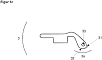
- Seitenansicht eines nicht erfindungsgemäßen Hebelarms
- Figur 1d
- Seitenansicht des Andruckabschnitts des Hebelarms
- Figur 1e
- Querschnitt des Dichtrings
- Figur 2
- Querschnitt einer nicht erfindungsgemäßen Hebelarmkupplung in der offenen Position
- Figur 3
- Querschnitt der Hebelarmkupplung in der geschlossenen Position
- Figur 4
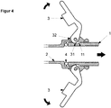
- Querschnitt der Hebelarmkupplung in der Zwischenposition
- Figur 5
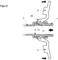
- Querschnitt der Hebelarmkupplung in einer Position zwischen der Zwischenposition und der offenen Position
- Figur 6
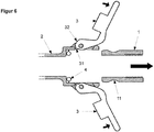
- Querschnitt der Hebelarmkupplung in der offenen Position
-
- Figur 7a
- Detailansicht der Hebelarmkupplung in der Nähe eines Dichtrings mit quadratischen Profil, in der geschlossenen Position
- Figur 7b
- Detailansicht der Hebelarmkupplung in der Nähe eines Dichtrings mit quadratischen Profil, in einer Position zwischen der geschlossenen Position und der Zwischenposition
- Figur 7c
- Detailansicht der Hebelarmkupplung in der Nähe eines Dichtrings mit quadratischen Profil, in der Zwischenposition
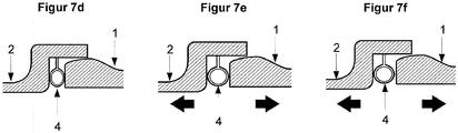
- Figur 7d
- Detailansicht der Hebelarmkupplung in der Nähe eines Dichtrings, in der geschlossenen Position
- Figur 7e
- Detailansicht der Hebelarmkupplung in der Nähe eines Dichtrings, in einer Position zwischen der geschlossenen Position und der Zwischenposition
- Figur 7f
- Detailansicht der Hebelarmkupplung in der Nähe eines Dichtrings, in der Zwischenposition
- Figur 8
- Seitenansicht des erfindungsgemäßen Hebelarms
- Figur 9a
- Verklebung der Hülle um den Kern des Dichtrings
- Figur 9b
- Verklebung der Hülle um den Kern des Dichtrings mit dazwischenliegender Verbindungsschicht.
- Eine Hebelarmkupplung besteht aus einer Vaterkupplung 1, einer Mutterkupplung 2, zwei Hebelarmen 3 und einem Dichtring 4 (
Figuren 1a-e ). DieFigur 2 zeigt, wie diese Elemente in der Hebelarmkupplung zusammengesetzt sind. Die Vaterkupplung 1 weist eine Umfangsnut 11 und ein Verbindungselement 12 zur Verbindung mit einer Schlauchleitung auf, beispielsweise ein Gewinde (Figur 1a ). Die Mutterkupplung 2 bildet einen Aufnahmebereich 21, in den die Vaterkupplung 1 eingeführt werden kann (Figur 1b ). Sie weist zudem zwei gegenüberliegende radiale Eingriffsöffnungen 22 auf, die mit einem Schwenkbolzen 23 versehen sind. Die Hebelarme 3 weisen einen abgerundeten Andruckabschnitt 3a auf, der einen Nocken 31 und eine Andruckfläche 32 umfasst (Figur 1c ). Im Andruckabschnitt 3a befindet sich zudem eine Öffnung 33, die zur Befestigung der Hebelarme 3 an den Schwenkbolzen 23 der Mutterkupplung 2 dient. Die Hebelarme 3 sind also um eine Drehachse 34 schwenkbar angeordnet, welche durch die Mitte der Öffnung 33 und des Schwenkbolzens 23 durchgeht (Figur 1d ). Die Öffnung 33 ist im Andruckabschnitt 3a exzentrisch angeordnet, damit die Dicke des Andruckabschnitts 3a um die Drehachse 34 herum nicht gleichmäßig ist. Im Folgenden werden vier bestimmte Dicken des Andruckabschnitts 3a in verschiedenen Richtungen um die Drehachse 34 herum definiert, die für die Erfindung von besonderem Interesse sind: - Dicke a: zwischen der Drehachse 34 und der Andruckfläche 32;
- Dicke b: zwischen der Drehachse 34 und der Andruckfläche 32 in der Nähe des Nockens 31;
- Dicke c: zwischen der Drehachse 34 und dem äußersten Ende des Nockens 31;
- Dicke d: zwischen der Drehachse 34 und dem Rand des Andruckabschnitts 3a auf der anderen Seite des Nockens 31.
- Wie in der
Figur 1d ersichtlich, sind die relativen Größen dieser Dicken a, b, c und d wie folgt: a > c > b > d. Je nach Position des Hebelarms 3 um den Schwenkbolzen 23 greift also der Andruckabschnitt 3a durch die radiale Eingriffsöffnung 22 im Aufnahmebereich 21 der Mutterkupplung 2 mehr oder weniger tief ein (Figuren 3-5 ). In der offenen Position derFigur 2 weist der Andruckabschnitt 3a von der Drehachse 34 aus und in der Richtung des Aufnahmebereichs 21 eine Dicke d auf. Erfindungsgemäß ist diese Dicke d genügend klein, damit der Andruckabschnitt 3a im Aufnahmegehäuse 21 nicht eingreift, und die Vaterkupplung 1 in die Mutterkupplung 2 frei ein-und ausgeführt werden kann. Zur Kopplung der Schlauchleitungen wird die Vaterkupplung 1 in den Aufnahmebereich 21 der Mutterkupplung eingefahren und die Hebelarme 3 von der offenen Position zur geschlossenen Position geschwenkt (Figur 3). In der geschlossenen Position weist der Andruckabschnitt 3a von der Drehachse 34 aus und in der Richtung des Aufnahmebereichs 21 eine Dicke a auf. Dabei greift die Andruckfläche 32 in die entsprechende Umfangsnut 11 der Vaterkupplung klemmend ein, wodurch die Vaterkupplung im Aufnahmebereich 21 der Mutterkupplung fest und sicher verankert ist. Wichtig ist für die Dichtheit der Verbindung zwischen den Kupplungsteilen 1-2 , dass die Vaterkupplung 1 in der geschlossenen Position am Dichtring 4 nicht nur leicht anstoßt, sondern diesen gegen die Mutterkupplung 2 presst. - Es ist vorgesehen, dass die Entkopplung der Hebelarmkupplung gemäß einem zweistufigen Vorgang erfolgt. In der ersten Stufe des Entkopplungsvorgangs werden die Hebelarme 3 von der geschlossenen Position der
Figur 3 zur Zwischenposition derFigur 4 geschwenkt. In der Zwischenposition weist der Andruckabschnitt 3a von der Drehachse 34 aus und in der Richtung des Aufnahmebereichs 21 eine Dicke b auf. Da die Dicke b kleiner als die Dicke a der geschlossenen Position ist, lockert sich der Griff um die Umfangsnut 11 der Vaterkupplung 1, so dass sich die Kupplungsteilen 1-2 leicht auseinander bewegen. Stehen die Schlauchleitungen unter Druck, erfolgt diese Auseinanderbewegung spontan, bis die Vaterkupplung 1 von dem vorstehenden Nocken 31 in der Zwischenposition derFigur 4 blockiert wird. Zur Vervollständigung der Entkopplung werden die Hebelarme 3 weiter von der Zwischenposition derFigur 4 zur Position derFigur 5 umgeschwenkt. In dieser Position weist der Andruckabschnitt 3a von der Drehachse 34 aus und in der Richtung des Aufnahmebereichs 21 eine Dicke c auf. Da der Abstand c grösser als der Abstand b der Zwischenposition ist, werden die Kupplungsteile 1-2 wieder leicht aufeinander zu geschoben (Figur 5 ), bevor sie in der anschließenden offenen Position komplett entkoppelt werden (Figur 6 ). - Zusammenfassend wird die Vaterkupplung beim Entkoppeln nicht direkt aus dem Aufnahmegehäuse gefahren, sondern:
- in einer ersten Stufe: von der geschlossenen Position zuerst leicht nach außen in die Zwischenposition bewegt;
- in einer zweiten Stufe: von der Zwischenposition dann wieder leicht nach innen bewegt;
- und schlussendlich in der offenen Position komplett entkoppelt, wobei sie aus der Mutterkupplung vollständig herausgezogen werden kann.
- Falls die Schlauchleitungen unter Druck stehen, erfolgt die erste Stufe des Entkopplungsvorgangs mühelos, da der Druck die Kupplungsteile 1-2 auseinander treibt. In der zweiten Stufe des Entkopplungsvorgangs werden die Kupplungsteile 1-2 allerdings wieder aufeinander zu bewegt, d.h. entgegen der Druckrichtung. Ein Ausschlag der Hebelarme 3 und der Kupplungsteile 1-2 aus der Zwischenposition der
Figur 4 ist somit ausgeschlossen, da jede Bewegung der Hebelarme 3 ein tieferes Eingreifen der Andruckfläche 32 oder des Nockens 31 im Aufnahmebereich 21 mit sich zieht und die Kupplungsteile 1-2 entgegen der Druckkraft bewegt werden. Wenn die Schlauchleitungen unter hohem Druck stehen, werden die Kupplungsteile 1-2 derart heftig auseinander gedrückt, dass ein Bediener sie auch mithilfe der Hebelarme 3 nur mit großer Kraft auseinander bringen kann. In der Zwischenposition ist die Hebelarmkupplung also blockiert. - Demzufolge ist erfindungsgemäß vorgesehen, den Überdruck in der Zwischenposition über den Dichtring 4 aus dem Schlauchsystem entweichen zu lassen. Dafür wird die Verbindung zwischen Mutter- und Vaterkupplung undicht gemacht, d.h., dass ein Durchgang ermöglicht wird, welcher zulässt, dass der Überdruck zwischen dem Dichtring 4 und den Kupplungsteilen 1-2 entweichen kann. Bei herkömmlichen Hebelarmkupplungen werden Dichtringe 4 mit quadratischem oder rechteckigem Profil eingesetzt, welche in der geschlossenen Position mit den Kupplungsteilen 1-2 eine möglichst große Kontaktfläche aufweisen und somit eine gute Dichtung der Verbindung gewährleisten (
Figur 7a ). Wenn die Kupplungsteile 1-2 von der geschlossenen Position zur Zwischenposition auseinander bewegt werden, dehnt sich der komprimierte Dichtring 4 aus (Figur 7b ). Der Dichtring 4 mit quadratischem oder rechteckigem Profil, dehnt sich seitlich gleichmäßig aus und die Kontaktfläche mit beiden Kupplungsteilen 1-2 bleibt gleich. Trotz der Bewegung der Kupplungsteile voneinander weg bleibt also die Verbindung dicht wie in der geschlossenen Position, bis der Dichtring 4 seine ursprüngliche Form wiederfindet, sich von den Kupplungsteilen 1-2 trennt und die Verbindung plötzlich komplett undicht wird (Figur 7c ). - In der vorliegenden Erfindung soll in der Zwischenposition der Überdruck aus dem Schlauchsystem über den Dichtring allmählich und kontrolliert entweichen. Dies wird dadurch erreicht, dass der Dichtring 4 und die Vaterkupplung 1 nicht plötzlich getrennt werden. Vielmehr wird die Kontaktfläche zwischen dem Dichtring 4 und der Vaterkupplung 1 allmählich verkleinert, so dass die Dichtheit der Verbindung allmählich abnimmt und der Überdruck graduell entweichen kann.
- Es ist vorgesehen, einen Dichtring 4 mit rundem Profil in der Hebelarmkupplung einzusetzen (
Figur 7d-f ). Während der Bewegung der Kupplungsteile 1-2 von der geschlossenen Position (Figur 7d ) zur Zwischenposition (Figur 7e ) dehnt sich der komprimierte ovale Dichtring 4 seitlich so aus, dass die Kontaktfläche zu den beiden Kupplungsteilen reduziert wird, da der Dichtring 4 zu seiner ursprünglichen runden Form zurückkehrt. Die Dichtheit der Verbindung nimmt also graduell ab und der Überdruck aus der Schlauchleitung kann so langsam und kontrolliert abgebaut werden. Schläge und schnelle Bewegungen der Kupplungsteile und Hebelarme können also vermieden werden. Um eine genügende Dichtheit der Verbindung bei einem runden Dichtring 4 zu erreichen, sind vorzugsweise Dichtringe 4 mit größerem Durchmesser als der Standard-Dichtring mit Rechteckprofil zu verwenden, die dann auch stärker zwischen beiden Kupplungsteilen 1-2 komprimiert und verformt werden. Umgekehrt ist theoretisch auch möglich, das äußerste Ende der Vaterkupplung 1 abzurunden, statt einen Dichtring 4 mit rundem Profil einzusetzen um denselben Effekt zu erzielen. Eine Abänderung der Vaterkupplung 1 ist aber unerwünscht, da die Vaterkupplung ein normiertes Standard-Bauteil ist. Daher ist es erfindungsgemäß vorgesehen, die Gestaltung des bzw. der Hebelarme 3 der Mutterkupplung 2, welche die Vaterkupplung 1 direkt steuern, zu verbessern. Diese können mit relativ geringem Aufwand an einer bestehenden Standard Kupplung ausgewechselt werden. Die Hebelarm 3 wird derart angepasst, dass ein Nocken 31, wie dieser aus dem Stand der Technik bekannt ist, des Hebelarms 3 abgerundet wird, so dass der Nocken 31 eine geschwungene aber spitz zulaufende Form aufweist und nicht eckig aus dem Andruckabschnitt 3a des Hebelarms 3 hervorsteht (Figur 8 ). Unter dem Ausdruck "Hebelarm 3 mit geschwungenen Nocken 31" ist ein Hebelarm 3 zu verstehen, wobei die Andruckfläche 3a des Hebelarms 3 zwischen der geschlossenen Position und der Zwischenposition immer tangential im Kontakt mit der Vaterkupplung steht. Herkömmliche eckige Nocken 31 bewirken, dass die Kupplungsteile 1-2 abrupt und mit großer Kraft voneinander weg geschleudert werden. Das anschließende Stoppen dieses Ausschlags in der blockierten Zwischenposition kann in der Leitung einen Rückschlageffekt auslösen, der die Hebelarmkupplung, die Schlauchleitungen und allfällige Ventile beschädigen könnte. Zudem erfolgt die Auseinanderbewegung von der geschlossenen Position mit kompletter Dichtheit zur Zwischenposition mit kompletter Trennung zwischen dem Dichtring und den Kupplungsteilen 1-2 auf einmal, so dass der Überdruck plötzlich entweicht. Mit einem geschwungenen Nocken 31 wird die Vaterkupplung allmählich aus der Mutterkupplung herausgefahren, bevor sie an der Spitze des Nockens 31 vollständig blockiert wird. Somit nimmt die Kontaktfläche zwischen dem Dichtring 4 und der Vaterkupplung 1 nur allmählich ab, was eine langsame und kontrollierte Druckentlassung gewährleistet. Da bereits vor dem Erreichen der blockierten Position und auch in dieser Position der Dichtring 4 nicht komplett abdichtet, kann der Überdruck in der Leitung abgebaut werden, bis dann ohne übertriebenen Kraftaufwand der Hebelarm über den spitz zulaufenden Teil bewegt werden kann, so dass die Kupplung komplett geöffnet ist. - In einer Variante der Hebelarmkupplung umfasst der Dichtring 4 einen Kern 41 aus elastischem Material (
Figur 1e ) wie Gummi oder Kautschuk, beispielsweise aus Viton®. Das elastische Kernmaterial 41 dient dazu, dass der Dichtrings 4 stark komprimiert werden kann, damit er in der geschlossenen Position zwischen den Kupplungsteilen 1-2 stark verformt wird und die Verbindungsfläche zu den Kupplungsteilen möglichst groß wird, so dass eine dichte Verbindung entsteht. Elastische Materialien wie Kautschuk weisen allerdings meistens einen hohen Reibungskoeffizient auf und haften daher an den Kupplungsteilen 1-2. Es besteht also weiterhin die Gefahr, dass derartige Dichtringe 4 während der Bewegung der Kupplungsteile 1-2 voneinander weg, an der Vaterkupplung 1 haften bleiben und sich nur plötzlich und stoßweise lösen, was wiederum zu Schlägen führen kann. Ebenfalls ist möglich, dass sich ein Dichtring 4 mit Rundprofil verdrehen kann, so dass die Elastizität unregelmäßig wird, oder der Ring sogar aus der gewünschten Position weg bewegt wird. Um den Überdruck kontrolliert entweichen zu lassen ist also sinnvoll, wenn die Haftung des Dichtrings reduziert ist. Eine besonders vorteilhafte Ausführungsvariante sieht also vor, dass der Kern 41 des Dichtrings 4 mit einer Hülle 42 aus einem zweiten Material umgeben ist, das weniger haftend ist und einen niedrigen Reibungskoeffizient aufweist. Beispielsweise ist porenfreies PTFE (Teflon) eine gute Materialwahl, weil PTFE diese Kriterien erfüllt und zusätzlich eine hervorragende chemische Reaktionsträgheit aufweist. Das hat den zusätzlichen Vorteil, dass der Dichtring auch bei stark reaktiven Medien, welche durch die Schlauchleitungen befördert werden, sich nicht oder nur wenig abnützt und eine große Langlebigkeit aufweist. - In einem möglichen Herstellungsverfahren wird die Hülle 42 um den Dichtring 4 herum gewickelt und verklebt (
Figur 9a ). Auf einer Seite des Dichtrings 4 werden beide Enden der Hülle 42 nahtlos zusammengeklebt oder zusammengeschweißt. Aufgrund der bekannten Antihaftwirkung von PTFE ist es jedoch schwierig, zwei PTFE Teile genügend fest zu verkleben oder zu verschweißen. Aufgrund des hohen Drucks und der wiederholten Verformungen des Dichtrings 4 ist die Gefahr, dass die Verbindung zwischen den beiden Enden der Hülle 42 sich allmählich auflöst oder sogar plötzlich aufplatzt recht groß. Um dies zu vermeiden muss die Verbindung sehr stark sein. Beim Verkleben oder Verschweißen muss also dafür gesorgt werden, dass die Haftung genügend stark ist. Diese Haftung kann verbessert werden, indem die zu verklebenden Flächen vorgängig bearbeitet werden. Sie könnten z.B. aufgeraut, mit Rillen versehen oder chemisch bearbeitet werden. Zusätzlich kann ein spezieller Klebstoffs oder eine Zwischenschicht verwendet werden, welcher die Verbindung stärkt. In einer Ausführungsvariante ist vorgesehen, dass die Verbindung zwischen den beiden Enden der Hülle 42 mit einer dazwischenliegenden Verbindungsschicht 44 verstärkt ist (Figur 9b ). Diese Verbindungsschicht 44 kann beispielsweise aus Perfluoroalkoxy Alkan (PFA) bestehen. - Da der Dichtring aus einem wenig haftenden Material besteht und aufgrund des runden Profils nicht genau in die Aussparung in der Mutterkupplung hineinpasst, kann dieser unter Umständen verrutschen oder nicht über den gesamten Umfang im selben Abstand zur äußeren Umrandung liegen, was auf die Dichtung einen negativen Einfluss haben kann. Daher ist in einer weiteren Ausführungsvariante vorgesehen, dass der Dichtring einen radialen Abstandhalter 43 aufweist, damit er im richtigen und vor allem auch gleichmäßigen Abstand von den Seitenwänden der Mutterkupplung zentriert festgehalten wird (
Figuren 2-6 ). Dieser Abstandhalter 43 kann beispielsweise ein vorstehender Teil der Hülle 42 sein (Figuren 9a-b ). Bevorzugterweise kann der verklebte Teil der Hülle 42 gleichzeitig den Abstandhalter 43 bilden.
Claims (1)
- Verbindungssystem für Schlauchleitungen mit einer Hebelarmkupplung, bestehend aus einer Vaterkupplung (1), einer Mutterkupplung (2), zwei Hebelarmen (3) und einem Dichtring (4), wobei die Mutterkupplung (2) einen Aufnahmebereich (21) aufweist, die Vaterkupplung (1) in diesen Aufnahmebereich (21) eingeführt werden kann, der Dichtring (4) in den Aufnahmebereich (21) der Mutterkupplung (2) eingelegt ist, die Hebelarme (3) an der Mutterkupplung (2) um eine Drehachse (34) schwenkbar angeordnet sind, einen Andruckabschnitt (3a) zur Vaterkupplung (1) mit einem Nocken (31) aufweisen und eine offene Position, eine geschlossene Position, sowie eine Zwischenposition einnehmen können, der Andruckabschnitt (3a) von der Drehachse (34) aus und in der Richtung des Aufnahmebereichs (21) in der offenen Position eine Dicke d aufweist, in der geschlossenen Position eine Dicke a und in der Zwischenposition, in der Nähe des Nockens(31), eine Dicke b, und zwischen der Drehachse (34) und dem äussersten Ende des Nockens (31) eine Dicke c, mit a > c > b > d so dass beim Entkoppeln mit Schwenken der Hebelarme (3) von der geschlossenen Position zur Zwischenposition die Vater- und Mutterkupplung (1, 2) von einander weg bewegt werden, und mit Schwenken der Hebelarme (3) von der Zwischenposition zur offenen Position die Vater- und Mutterkupplung (1, 2) aufeinander zu bewegt werden, bevor sie vollständig entkoppelt werden, wobei die Dicke d genügend klein ist, damit der Andruckabschnitt (3a) im Aufnahmegehäuse (21) nicht eingreift, und die Vaterkupplung (1) in die Mutterkupplung (2) frei ein-und ausgeführt werden kann, wobei der Nocken (31) des Hebelarms (3) abgerundet ist, so dass der Nocken (31) eine geschwungene aber spitz zulaufende Form aufweist und nicht eckig aus dem Andruckabschnitt (3a) des Hebelarms (3) hervorsteht, so dass der Andruckabschnitt (3a) des Hebelarms (3) zwischen der geschlossenen Position und der Zwischenposition immer tangential im Kontakt mit der Vaterkupplung (1) steht, und wobei der Anpressdruck zwischen der Mutterkupplung (2) bzw. der Vaterkupplung (1) und dem Dichtring (4) so reduziert wird, dass ein Durchgang ermöglicht wird, damit der Dichtring (4) in der Zwischenposition nicht komplett abdichtet, und der Druck aus dem Schlauch entweichen kann.
Applications Claiming Priority (1)
| Application Number | Priority Date | Filing Date | Title |
|---|---|---|---|
| CH01322/16A CH713008A2 (de) | 2016-10-05 | 2016-10-05 | Verbindungssystem für Schlauchleitungen mit einer Hebelarmkupplung. |
Publications (3)
| Publication Number | Publication Date |
|---|---|
| EP3306166A2 EP3306166A2 (de) | 2018-04-11 |
| EP3306166A3 EP3306166A3 (de) | 2018-05-16 |
| EP3306166B1 true EP3306166B1 (de) | 2020-07-15 |
Family
ID=60153052
Family Applications (1)
| Application Number | Title | Priority Date | Filing Date |
|---|---|---|---|
| EP17194357.4A Active EP3306166B1 (de) | 2016-10-05 | 2017-10-02 | Verbindungssystem für schlauchleitungen mit einer hebelarmkupplung |
Country Status (2)
| Country | Link |
|---|---|
| EP (1) | EP3306166B1 (de) |
| CH (1) | CH713008A2 (de) |
Families Citing this family (2)
| Publication number | Priority date | Publication date | Assignee | Title |
|---|---|---|---|---|
| CN110397812B (zh) * | 2019-08-13 | 2020-10-16 | 湖北盛荣建设有限公司 | 一种建筑工程给水排水管道连接装置 |
| CN116447203B (zh) * | 2023-05-11 | 2026-01-16 | 中国核电工程有限公司 | 一种快速拆装的多级紧固系统及用于放射性环境的设备 |
Family Cites Families (8)
| Publication number | Priority date | Publication date | Assignee | Title |
|---|---|---|---|---|
| US3860274A (en) * | 1973-07-02 | 1975-01-14 | Richard L Ledstrom | Pipe coupling |
| US4519635A (en) * | 1982-09-29 | 1985-05-28 | Dover Corporation | Quick connect-disconnect coupling |
| US4618171A (en) * | 1983-08-18 | 1986-10-21 | Dover Corporation | Quick connect-disconnect coupling |
| GB2264986B (en) * | 1992-03-07 | 1996-02-28 | Dowty Seals Ltd | Ring seal |
| CN1213428A (zh) * | 1996-02-08 | 1999-04-07 | 沃威克·安德鲁·麦坚石 | 可锁定的联接件 |
| DE29707747U1 (de) | 1997-04-29 | 1997-06-26 | Chen, Waterson, Taichung | Anschlußstück mit zwei rohrförmigen, relativ zueinander drehbaren Gliedern |
| WO2009156357A1 (de) | 2008-06-27 | 2009-12-30 | Dieter K. Eich Maschinenbau | Hebelarmkupplung zur verbindung von schlauchleitungen |
| US8123256B1 (en) * | 2010-04-19 | 2012-02-28 | Jeffrey Hartman | Safety lock for cam lock fitting |
-
2016
- 2016-10-05 CH CH01322/16A patent/CH713008A2/de unknown
-
2017
- 2017-10-02 EP EP17194357.4A patent/EP3306166B1/de active Active
Non-Patent Citations (1)
| Title |
|---|
| None * |
Also Published As
| Publication number | Publication date |
|---|---|
| CH713008A2 (de) | 2018-04-13 |
| EP3306166A2 (de) | 2018-04-11 |
| EP3306166A3 (de) | 2018-05-16 |
Similar Documents
| Publication | Publication Date | Title |
|---|---|---|
| EP2757297B1 (de) | Vakuumanordnung und Verwendung einer Verbindungsvorrichtung | |
| DE19950619C1 (de) | Rohrkupplung mit Schnellverschluß und Rohrflansch zur Verwendung mit einer solchen Rohrkupplung | |
| EP3377796B1 (de) | Kupplungselement für eine kupplung zur verbindung von druckmittelleitungen | |
| EP2710972B1 (de) | Drehventilkörper für Austragsvorrichtung für Knochenzemente | |
| DE1475683A1 (de) | Kupplungsdichtring | |
| EP3306166A2 (de) | Verbindungssystem für schlauchleitungen mit einer hebelarmkupplung | |
| DE3346069A1 (de) | Rohrverbindung mit fernbetaetigbaren festlege- und loeseeinrichtungen | |
| WO2004082079A1 (de) | Sicherungselement zum sichern gegen öffnen einer steckverbindung zwischen einem kabelbaumstecker und einem kupplungsstecker. | |
| DE112015003838B4 (de) | Sicherheitsventil für Warmwasserbereiter | |
| EP3153754B1 (de) | Quetschflansch mit montagekontrolle | |
| EP2918354B1 (de) | Pressaufsatz zum axialen Verpressen von Werkstücken | |
| DE102012219058A1 (de) | Schnellspannmutter | |
| DE2415699B2 (de) | Zug- und schubgesicherte Schraubmuffen-Verbindung von Rohren, insb. duktilen Gußrohren | |
| DE60311085T2 (de) | Vorrichtung zur verbindung von rohrleitungen | |
| EP4356035A1 (de) | Pressverbindungssystem zum unlösbaren verbinden eines fittings und fitting | |
| DE202023102547U1 (de) | Verbindung für wasserführende Bauteile | |
| DE2746996A1 (de) | Rohrkupplung | |
| DE20214463U1 (de) | Symmetrische Schlauchkupplung | |
| EP3230639B1 (de) | Kupplungsteil für eine schraubkupplung für druckmittelleitungen | |
| DE10155362B4 (de) | Spannring zur Verbindung von Rohrenden | |
| DE2525760C3 (de) | Rohrkupplung | |
| DE2746986C3 (de) | Vorrichtung zum Verbinden eines Schlauchendes mit einem Anschlußstutzen | |
| DE102020101262B4 (de) | Kupplungseinrichtung zum Verbinden von hydraulischen Leitungen und Prüfsystem mit einer Kupplungseinrichtung | |
| DE19841802C2 (de) | Fitting zum Anschluß eines Rohres | |
| EP0592763B1 (de) | Kupplungsstück zum fluiddichten Ankoppeln einer Fluidleitung an ein Gegenstück |
Legal Events
| Date | Code | Title | Description |
|---|---|---|---|
| PUAI | Public reference made under article 153(3) epc to a published international application that has entered the european phase |
Free format text: ORIGINAL CODE: 0009012 |
|
| STAA | Information on the status of an ep patent application or granted ep patent |
Free format text: STATUS: THE APPLICATION HAS BEEN PUBLISHED |
|
| AK | Designated contracting states |
Kind code of ref document: A2 Designated state(s): AL AT BE BG CH CY CZ DE DK EE ES FI FR GB GR HR HU IE IS IT LI LT LU LV MC MK MT NL NO PL PT RO RS SE SI SK SM TR |
|
| AX | Request for extension of the european patent |
Extension state: BA ME |
|
| PUAL | Search report despatched |
Free format text: ORIGINAL CODE: 0009013 |
|
| AK | Designated contracting states |
Kind code of ref document: A3 Designated state(s): AL AT BE BG CH CY CZ DE DK EE ES FI FR GB GR HR HU IE IS IT LI LT LU LV MC MK MT NL NO PL PT RO RS SE SI SK SM TR |
|
| AX | Request for extension of the european patent |
Extension state: BA ME |
|
| RIC1 | Information provided on ipc code assigned before grant |
Ipc: F16L 37/18 20060101AFI20180412BHEP |
|
| STAA | Information on the status of an ep patent application or granted ep patent |
Free format text: STATUS: REQUEST FOR EXAMINATION WAS MADE |
|
| 17P | Request for examination filed |
Effective date: 20181116 |
|
| RBV | Designated contracting states (corrected) |
Designated state(s): AL AT BE BG CH CY CZ DE DK EE ES FI FR GB GR HR HU IE IS IT LI LT LU LV MC MK MT NL NO PL PT RO RS SE SI SK SM TR |
|
| GRAP | Despatch of communication of intention to grant a patent |
Free format text: ORIGINAL CODE: EPIDOSNIGR1 |
|
| STAA | Information on the status of an ep patent application or granted ep patent |
Free format text: STATUS: GRANT OF PATENT IS INTENDED |
|
| INTG | Intention to grant announced |
Effective date: 20200227 |
|
| GRAS | Grant fee paid |
Free format text: ORIGINAL CODE: EPIDOSNIGR3 |
|
| GRAA | (expected) grant |
Free format text: ORIGINAL CODE: 0009210 |
|
| STAA | Information on the status of an ep patent application or granted ep patent |
Free format text: STATUS: THE PATENT HAS BEEN GRANTED |
|
| AK | Designated contracting states |
Kind code of ref document: B1 Designated state(s): AL AT BE BG CH CY CZ DE DK EE ES FI FR GB GR HR HU IE IS IT LI LT LU LV MC MK MT NL NO PL PT RO RS SE SI SK SM TR |
|
| REG | Reference to a national code |
Ref country code: CH Ref legal event code: EP Ref country code: GB Ref legal event code: FG4D Free format text: NOT ENGLISH |
|
| REG | Reference to a national code |
Ref country code: IE Ref legal event code: FG4D Free format text: LANGUAGE OF EP DOCUMENT: GERMAN |
|
| REG | Reference to a national code |
Ref country code: DE Ref legal event code: R096 Ref document number: 502017006175 Country of ref document: DE |
|
| REG | Reference to a national code |
Ref country code: AT Ref legal event code: REF Ref document number: 1291416 Country of ref document: AT Kind code of ref document: T Effective date: 20200815 |
|
| REG | Reference to a national code |
Ref country code: CH Ref legal event code: NV Representative=s name: EUROMAIER AG, CH |
|
| REG | Reference to a national code |
Ref country code: LT Ref legal event code: MG4D |
|
| REG | Reference to a national code |
Ref country code: NL Ref legal event code: MP Effective date: 20200715 |
|
| PG25 | Lapsed in a contracting state [announced via postgrant information from national office to epo] |
Ref country code: GR Free format text: LAPSE BECAUSE OF FAILURE TO SUBMIT A TRANSLATION OF THE DESCRIPTION OR TO PAY THE FEE WITHIN THE PRESCRIBED TIME-LIMIT Effective date: 20201016 Ref country code: SE Free format text: LAPSE BECAUSE OF FAILURE TO SUBMIT A TRANSLATION OF THE DESCRIPTION OR TO PAY THE FEE WITHIN THE PRESCRIBED TIME-LIMIT Effective date: 20200715 Ref country code: NO Free format text: LAPSE BECAUSE OF FAILURE TO SUBMIT A TRANSLATION OF THE DESCRIPTION OR TO PAY THE FEE WITHIN THE PRESCRIBED TIME-LIMIT Effective date: 20201015 Ref country code: FI Free format text: LAPSE BECAUSE OF FAILURE TO SUBMIT A TRANSLATION OF THE DESCRIPTION OR TO PAY THE FEE WITHIN THE PRESCRIBED TIME-LIMIT Effective date: 20200715 Ref country code: PT Free format text: LAPSE BECAUSE OF FAILURE TO SUBMIT A TRANSLATION OF THE DESCRIPTION OR TO PAY THE FEE WITHIN THE PRESCRIBED TIME-LIMIT Effective date: 20201116 Ref country code: HR Free format text: LAPSE BECAUSE OF FAILURE TO SUBMIT A TRANSLATION OF THE DESCRIPTION OR TO PAY THE FEE WITHIN THE PRESCRIBED TIME-LIMIT Effective date: 20200715 Ref country code: BG Free format text: LAPSE BECAUSE OF FAILURE TO SUBMIT A TRANSLATION OF THE DESCRIPTION OR TO PAY THE FEE WITHIN THE PRESCRIBED TIME-LIMIT Effective date: 20201015 Ref country code: LT Free format text: LAPSE BECAUSE OF FAILURE TO SUBMIT A TRANSLATION OF THE DESCRIPTION OR TO PAY THE FEE WITHIN THE PRESCRIBED TIME-LIMIT Effective date: 20200715 Ref country code: ES Free format text: LAPSE BECAUSE OF FAILURE TO SUBMIT A TRANSLATION OF THE DESCRIPTION OR TO PAY THE FEE WITHIN THE PRESCRIBED TIME-LIMIT Effective date: 20200715 |
|
| PG25 | Lapsed in a contracting state [announced via postgrant information from national office to epo] |
Ref country code: PL Free format text: LAPSE BECAUSE OF FAILURE TO SUBMIT A TRANSLATION OF THE DESCRIPTION OR TO PAY THE FEE WITHIN THE PRESCRIBED TIME-LIMIT Effective date: 20200715 Ref country code: RS Free format text: LAPSE BECAUSE OF FAILURE TO SUBMIT A TRANSLATION OF THE DESCRIPTION OR TO PAY THE FEE WITHIN THE PRESCRIBED TIME-LIMIT Effective date: 20200715 Ref country code: LV Free format text: LAPSE BECAUSE OF FAILURE TO SUBMIT A TRANSLATION OF THE DESCRIPTION OR TO PAY THE FEE WITHIN THE PRESCRIBED TIME-LIMIT Effective date: 20200715 Ref country code: IS Free format text: LAPSE BECAUSE OF FAILURE TO SUBMIT A TRANSLATION OF THE DESCRIPTION OR TO PAY THE FEE WITHIN THE PRESCRIBED TIME-LIMIT Effective date: 20201115 |
|
| PG25 | Lapsed in a contracting state [announced via postgrant information from national office to epo] |
Ref country code: NL Free format text: LAPSE BECAUSE OF FAILURE TO SUBMIT A TRANSLATION OF THE DESCRIPTION OR TO PAY THE FEE WITHIN THE PRESCRIBED TIME-LIMIT Effective date: 20200715 |
|
| REG | Reference to a national code |
Ref country code: DE Ref legal event code: R097 Ref document number: 502017006175 Country of ref document: DE |
|
| PG25 | Lapsed in a contracting state [announced via postgrant information from national office to epo] |
Ref country code: EE Free format text: LAPSE BECAUSE OF FAILURE TO SUBMIT A TRANSLATION OF THE DESCRIPTION OR TO PAY THE FEE WITHIN THE PRESCRIBED TIME-LIMIT Effective date: 20200715 Ref country code: IT Free format text: LAPSE BECAUSE OF FAILURE TO SUBMIT A TRANSLATION OF THE DESCRIPTION OR TO PAY THE FEE WITHIN THE PRESCRIBED TIME-LIMIT Effective date: 20200715 Ref country code: SM Free format text: LAPSE BECAUSE OF FAILURE TO SUBMIT A TRANSLATION OF THE DESCRIPTION OR TO PAY THE FEE WITHIN THE PRESCRIBED TIME-LIMIT Effective date: 20200715 Ref country code: DK Free format text: LAPSE BECAUSE OF FAILURE TO SUBMIT A TRANSLATION OF THE DESCRIPTION OR TO PAY THE FEE WITHIN THE PRESCRIBED TIME-LIMIT Effective date: 20200715 Ref country code: CZ Free format text: LAPSE BECAUSE OF FAILURE TO SUBMIT A TRANSLATION OF THE DESCRIPTION OR TO PAY THE FEE WITHIN THE PRESCRIBED TIME-LIMIT Effective date: 20200715 Ref country code: RO Free format text: LAPSE BECAUSE OF FAILURE TO SUBMIT A TRANSLATION OF THE DESCRIPTION OR TO PAY THE FEE WITHIN THE PRESCRIBED TIME-LIMIT Effective date: 20200715 |
|
| PLBE | No opposition filed within time limit |
Free format text: ORIGINAL CODE: 0009261 |
|
| STAA | Information on the status of an ep patent application or granted ep patent |
Free format text: STATUS: NO OPPOSITION FILED WITHIN TIME LIMIT |
|
| PG25 | Lapsed in a contracting state [announced via postgrant information from national office to epo] |
Ref country code: AL Free format text: LAPSE BECAUSE OF FAILURE TO SUBMIT A TRANSLATION OF THE DESCRIPTION OR TO PAY THE FEE WITHIN THE PRESCRIBED TIME-LIMIT Effective date: 20200715 |
|
| 26N | No opposition filed |
Effective date: 20210416 |
|
| PG25 | Lapsed in a contracting state [announced via postgrant information from national office to epo] |
Ref country code: MC Free format text: LAPSE BECAUSE OF FAILURE TO SUBMIT A TRANSLATION OF THE DESCRIPTION OR TO PAY THE FEE WITHIN THE PRESCRIBED TIME-LIMIT Effective date: 20200715 Ref country code: LU Free format text: LAPSE BECAUSE OF NON-PAYMENT OF DUE FEES Effective date: 20201002 Ref country code: SK Free format text: LAPSE BECAUSE OF FAILURE TO SUBMIT A TRANSLATION OF THE DESCRIPTION OR TO PAY THE FEE WITHIN THE PRESCRIBED TIME-LIMIT Effective date: 20200715 |
|
| PG25 | Lapsed in a contracting state [announced via postgrant information from national office to epo] |
Ref country code: SI Free format text: LAPSE BECAUSE OF FAILURE TO SUBMIT A TRANSLATION OF THE DESCRIPTION OR TO PAY THE FEE WITHIN THE PRESCRIBED TIME-LIMIT Effective date: 20200715 |
|
| PG25 | Lapsed in a contracting state [announced via postgrant information from national office to epo] |
Ref country code: TR Free format text: LAPSE BECAUSE OF FAILURE TO SUBMIT A TRANSLATION OF THE DESCRIPTION OR TO PAY THE FEE WITHIN THE PRESCRIBED TIME-LIMIT Effective date: 20200715 Ref country code: MT Free format text: LAPSE BECAUSE OF FAILURE TO SUBMIT A TRANSLATION OF THE DESCRIPTION OR TO PAY THE FEE WITHIN THE PRESCRIBED TIME-LIMIT Effective date: 20200715 Ref country code: CY Free format text: LAPSE BECAUSE OF FAILURE TO SUBMIT A TRANSLATION OF THE DESCRIPTION OR TO PAY THE FEE WITHIN THE PRESCRIBED TIME-LIMIT Effective date: 20200715 |
|
| PG25 | Lapsed in a contracting state [announced via postgrant information from national office to epo] |
Ref country code: MK Free format text: LAPSE BECAUSE OF FAILURE TO SUBMIT A TRANSLATION OF THE DESCRIPTION OR TO PAY THE FEE WITHIN THE PRESCRIBED TIME-LIMIT Effective date: 20200715 |
|
| REG | Reference to a national code |
Ref country code: CH Ref legal event code: U11 Free format text: ST27 STATUS EVENT CODE: U-0-0-U10-U11 (AS PROVIDED BY THE NATIONAL OFFICE) Effective date: 20251223 |
|
| PGFP | Annual fee paid to national office [announced via postgrant information from national office to epo] |
Ref country code: DE Payment date: 20251006 Year of fee payment: 9 |
|
| PGFP | Annual fee paid to national office [announced via postgrant information from national office to epo] |
Ref country code: GB Payment date: 20251002 Year of fee payment: 9 |
|
| PGFP | Annual fee paid to national office [announced via postgrant information from national office to epo] |
Ref country code: AT Payment date: 20251006 Year of fee payment: 9 |
|
| PGFP | Annual fee paid to national office [announced via postgrant information from national office to epo] |
Ref country code: FR Payment date: 20251002 Year of fee payment: 9 |
|
| PGFP | Annual fee paid to national office [announced via postgrant information from national office to epo] |
Ref country code: BE Payment date: 20251006 Year of fee payment: 9 |
|
| PGFP | Annual fee paid to national office [announced via postgrant information from national office to epo] |
Ref country code: CH Payment date: 20251223 Year of fee payment: 9 |
|
| PGFP | Annual fee paid to national office [announced via postgrant information from national office to epo] |
Ref country code: IE Payment date: 20251002 Year of fee payment: 9 |