EP3306004A1 - Self-shuttering construction system - Google Patents
Self-shuttering construction system Download PDFInfo
- Publication number
- EP3306004A1 EP3306004A1 EP17153562.8A EP17153562A EP3306004A1 EP 3306004 A1 EP3306004 A1 EP 3306004A1 EP 17153562 A EP17153562 A EP 17153562A EP 3306004 A1 EP3306004 A1 EP 3306004A1
- Authority
- EP
- European Patent Office
- Prior art keywords
- panels
- clips
- construction system
- self
- construction
- Prior art date
- Legal status (The legal status is an assumption and is not a legal conclusion. Google has not performed a legal analysis and makes no representation as to the accuracy of the status listed.)
- Withdrawn
Links
Images


Classifications
-
- E—FIXED CONSTRUCTIONS
- E04—BUILDING
- E04B—GENERAL BUILDING CONSTRUCTIONS; WALLS, e.g. PARTITIONS; ROOFS; FLOORS; CEILINGS; INSULATION OR OTHER PROTECTION OF BUILDINGS
- E04B2/00—Walls, e.g. partitions, for buildings; Wall construction with regard to insulation; Connections specially adapted to walls
- E04B2/84—Walls made by casting, pouring, or tamping in situ
- E04B2/86—Walls made by casting, pouring, or tamping in situ made in permanent forms
- E04B2/8635—Walls made by casting, pouring, or tamping in situ made in permanent forms with ties attached to the inner faces of the forms
- E04B2/8641—Walls made by casting, pouring, or tamping in situ made in permanent forms with ties attached to the inner faces of the forms using dovetail-type connections
-
- E—FIXED CONSTRUCTIONS
- E04—BUILDING
- E04B—GENERAL BUILDING CONSTRUCTIONS; WALLS, e.g. PARTITIONS; ROOFS; FLOORS; CEILINGS; INSULATION OR OTHER PROTECTION OF BUILDINGS
- E04B2/00—Walls, e.g. partitions, for buildings; Wall construction with regard to insulation; Connections specially adapted to walls
- E04B2/84—Walls made by casting, pouring, or tamping in situ
- E04B2/86—Walls made by casting, pouring, or tamping in situ made in permanent forms
- E04B2002/867—Corner details
-
- E—FIXED CONSTRUCTIONS
- E04—BUILDING
- E04B—GENERAL BUILDING CONSTRUCTIONS; WALLS, e.g. PARTITIONS; ROOFS; FLOORS; CEILINGS; INSULATION OR OTHER PROTECTION OF BUILDINGS
- E04B2/00—Walls, e.g. partitions, for buildings; Wall construction with regard to insulation; Connections specially adapted to walls
- E04B2/84—Walls made by casting, pouring, or tamping in situ
- E04B2/86—Walls made by casting, pouring, or tamping in situ made in permanent forms
- E04B2002/8676—Wall end details
Definitions
- the present invention relates to the field of building construction. It relates to an insulated modular modular building system for the realization of concrete walls.
- the modular block construction has the advantage of greatly simplifying the construction work or even allowing self-construction.
- Lightweight building elements are sought to reduce energy and thus costs related to their transport and their implementation.
- the ICP (Self-Contained Blocking System) system meets these demands. This system allows the realization of formwork in which a concrete veil is poured.
- the blocks currently on the market usually consist of two expanded polystyrene walls attached vertically spaced apart to allow formwork for the concrete. These blocks are assembled directly on site and once the floor height is achieved, the concrete is poured inside the polystyrene walls.
- the FR 2735803 discloses stackable self-contained building blocks stackable on each other and containing two walls connected by a frame structure.
- the frame has metal bars that extend into the walls. It is therefore not easy to cut the blocks to different sizes.
- This system also has the disadvantage of being bulky in transport and on site and being somewhat modular. It does not easily allow the realization of angles, let alone angles out of square.
- the document WO95 / 30805 plans to have spacers on top of each other.
- the document WO2006 / 063140 plans to use specific modules for angles. These systems are not economical.
- Another disadvantage of the existing blocks is not to have the possibility of screwing into the inner wall to suspend objects such as cabinets, etc.
- the inner insulating panels have two longitudinal faces, two lateral sides, an upper side and a lower side. One of the longitudinal faces is intended to be directed towards the inside of the block, the other towards the interior of the construction. The longitudinal face intended to be directed towards the inside of the block is provided with T-shaped notches, The outer insulating panels have two longitudinal faces, two lateral sides, an upper side and a lower side. One of the longitudinal faces is intended to be directed towards the inside of the block, the other towards the outside of the construction. The longitudinal face intended to be directed towards the inside of the block is provided with T-shaped notches.
- the clips have a T-shaped base adapted to fit into the notches, and a distal portion adapted to receive the reinforcement.
- the reinforcement consists of two longitudinal concrete bars connected perpendicularly by transverse bars in the form of a ladder.
- the inner and outer panels are provided on their upper and lower sides with a tenon and mortise type system allowing the vertical interlocking of one panel on another;
- the inner and outer panels are preferably provided on their lateral sides with a system and type mortise and tenon allowing the lateral interlocking of the panels into each other.
- the clips are adapted to receive horizontally, in their distal part, a longitudinal reinforcing bar of the reinforcement, the distal portion of the clips advantageously comprising a housing of shape corresponding to the shape of the longitudinal bars of the reinforcement, and a flap adapted to fix said bar .
- the Fig. 1 illustrates an inner panel 1 of a building system according to the invention.
- the panel 1 consists of two parts.
- a high density portion 2 is intended to constitute the outward facing face of the self-forming system and to the interior of the construction.
- the other part 4 consists of a low density insulating material. It is intended to be turned towards the interior of the self-offering system.
- High density means densities of the order of 150 to 210 gr / l, preferably of the order of 170 to 190 g / l.
- Materials having this type of density are, for example: expanded polystyrene, polyurethane or even wood.
- This high density makes it easy to hang elements of a kitchen, for example, or to make staircase forms without having to drill into the concrete veil.
- low density densities of the order of 20 to 50 g / l, preferably of the order of 30 to 40 g / l.
- materials of such density are the polyurethane, expanded polystyrene or any other material with a good insulation coefficient (0.020 to 0.12 in particular).
- Part 4 low density allows to be easily cut. Indeed, the laying of electric cables or water pipes can be done hot knife or cutter in this part 4, without having to reach the concrete veil.
- Voids are made by molding in the upper part of each of the parts 2 and 4 to form T-shaped notches 3, for the passage of the base 7 of the clips 6 (illustrated in FIG. fig.3 ).
- the two parts 2 and 4 of the panel 1 are thus mechanically connected by the installation of the clips 6.
- the Fig. 2 illustrates an outer panel 5 of a building system according to the invention.
- the panel 5 is much thicker than the inner panel 1 so as to achieve a thorough insulation of the construction. It is made of a light material and having a good insulation coefficient (0.020 to 0.12 in particular). This material may be of the same type as the low density material of the part 4 of the inner panel.
- T-shaped notches are also provided from the molding, in the upper part of the panel 5.
- the number of notches is here of the order of 5 per meter, so to avoid a risk of deformation under the effect of the pressure of the concrete during the filling but also to allow a uniform distribution over the entire height of the wall.
- the inner panels 1 and 5 have, at their upper side, protuberances 14 and at their lower side recesses (not shown) of corresponding shape so as to form a mortise-type interlocking to stack a panel to the vertical of another.
- the panels 1 and 5 also have on one of their lateral sides protuberances 15 and on the other side corresponding recesses to allow the interlocking panels side by side.
- the Fig. 3 illustrates the clips 6 according to the invention. They comprise a T-shaped base 7 adapted to fit into the notches 3 of the inner and outer panels and a distal portion 17.
- the distal portion 17 has an opening for the insertion of the concrete bars.
- the opening comprises a triangular portion 18 to facilitate the entry of the longitudinal bars 11a and 11b of the reinforcement 10, a rounded portion corresponding to the shape of the bars 11a and 11b, forming a housing 9 for these bars.
- a bar retaining system is provided by means of a flap 8 fixed on the clip 6 in a flexible manner to form a spring and prevent the bars 11a and 11b from being released from the reinforcement 10.
- a protrusion may also be provided on the flap 8 to improve the retaining bars 11a and 11b in their housing 9.
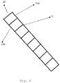
- the Fig. 4 illustrates the ladder-shaped reinforcement. It consists of two longitudinal bars 11a, 11b and transverse bars connecting them perpendicularly.
- the Fig. 5 illustrates a part of the mounted system.
- Caps 13 are inserted vertically on the sides of the assembly so as to close the cavity. Their placement is achieved in a single operation, once the complete assembly of the walls is achieved.
- the spacing between the inner panels 1 and the outer panels 5 is a function of the thickness of the desired concrete web. It must be sufficient so that the clips 6 of a panel do not touch the opposite panel. In this way, a discontinuity is achieved, filled by the concrete veil, which guarantees a perfect fire resistance and also ensures a sound break.
- the system according to the invention distinguishing the inner panel 1 from the outer panel 5 allows to shift the panels relative to each other on the site. This has the advantage of allowing, for example the installation of a window bay with beat without waste and without particular implementation.
- angles are very simple because the inner and outer panels are provided separately. It is therefore possible to offset laterally the inner panels 1 relative to the outer panels 5. No cutting is necessary.
- the resistance of the angle is provided by the reinforcement 10 which extends on one side, completely in the angel, or even by superposition, at the angle, the reinforcement 10 coming from each side. Clips 6 hold the reinforcement in the corner.
- the panels can be supplied in various dimensions.
- the thickness of the outer panel 5 is chosen according to the degree of insulation desired for the building.
- the lengths of the inner and outer panels may be different.
- the height of the inner and outer panels must be chosen so as to position the clips on the same height to advantageously position the reinforcement horizontally.
Landscapes
- Engineering & Computer Science (AREA)
- Architecture (AREA)
- Physics & Mathematics (AREA)
- Electromagnetism (AREA)
- Civil Engineering (AREA)
- Structural Engineering (AREA)
- Building Environments (AREA)
Abstract
La présente invention concerne un système de construction modulaire autocoffrant comportant : - des panneaux isolants intérieurs, - des panneaux isolants extérieurs, - des clips, - des ferraillages, - des bouchons. L'assemblage des éléments permet de fournir un système autocoffrant pour la construction de murs en béton. L'invention fournit un système performant en termes de volume de matière à transporter, de résistance mécanique, résistance au feu, de simplicité de montage, de réalisation d'angles.The present invention relates to a modular building system self-offering comprising: - interior insulating panels, - external insulating panels, - clips, - reinforcement, - the traffic jam. The assembly of the elements makes it possible to provide a self-installing system for the construction of concrete walls. The invention provides a system that is efficient in terms of the volume of material to be transported, the mechanical strength, the fire resistance, the simplicity of assembly, the production of angles.
Description
La présente invention a trait au domaine de la construction de bâtiments. Elle concerne un système de construction modulaire isolé et autocoffrant permettant la réalisation de murs de béton.The present invention relates to the field of building construction. It relates to an insulated modular modular building system for the realization of concrete walls.
Dans le domaine de la construction, la réalisation de bâtiments permettant une très haute isolation thermique est devenue un enjeu majeur.In the field of construction, the construction of buildings allowing very high thermal insulation has become a major issue.
D'autre part, des procédés de fabrication simples et donc économiques sont recherchés. La construction modulaire en blocs a l'avantage de simplifier fortement le travail de construction voire même de permettre l'auto-construction.On the other hand, simple and therefore economical manufacturing processes are sought. The modular block construction has the advantage of greatly simplifying the construction work or even allowing self-construction.
Des éléments de construction légers sont recherchés pour permettent de réduire l'énergie et donc les coûts liés à leurs transports et leur mise en oeuvre.Lightweight building elements are sought to reduce energy and thus costs related to their transport and their implementation.
Le système de construction en blocs autocoffrants isolés (ICP en anglais) répond à ces demandes. Ce système permet la réalisation de coffrage dans lequel un voile de béton est coulé.The ICP (Self-Contained Blocking System) system meets these demands. This system allows the realization of formwork in which a concrete veil is poured.
Les blocs actuellement présents sur le marché sont habituellement constitués de deux parois en polystyrène expansé attachées verticalement, de manière espacée pour permettre d'établir un coffrage pour le béton. Ces blocs sont assemblés directement sur le chantier et une fois la hauteur d'étage réalisée, le béton est coulé à l'intérieur des parois de polystyrènes.The blocks currently on the market usually consist of two expanded polystyrene walls attached vertically spaced apart to allow formwork for the concrete. These blocks are assembled directly on site and once the floor height is achieved, the concrete is poured inside the polystyrene walls.
Le
De nombreux systèmes prévoient l'espacement entre les parois à l'aide d'entretoises se fixant en les glissant verticalement dans des encoches des faces intérieures des deux parois. De tels systèmes sont par exemple décrits dans les documents
Pour la réalisation des angles, le document
Un autre inconvénient des blocs existants est de ne pas avoir la possibilité de visser dans la paroi intérieure pour suspendre des objets tels que armoires, etc..Another disadvantage of the existing blocks is not to have the possibility of screwing into the inner wall to suspend objects such as cabinets, etc.
De plus, il arrive que les blocs de coffrage existants se déforment ou s'éclatent côté intérieur avec la pression du béton coulé.In addition, it happens that the existing formwork blocks deform or burst on the inside with the pressure of the poured concrete.
Un besoin demeure quant à la fourniture d'un système de construction isolé autocoffrant qui soit plus performant, notamment en termes de volume de matière à transporter, de résistance mécanique, résistance au feu, de simplicité de montage, de réalisation d'angle et qui évite les pertes de matière.There is still a need to provide a self-contained insulated building system that is more efficient, particularly in terms of the volume of material to be transported, the mechanical strength, the fire resistance, the simplicity of assembly, the angle production, and avoids material losses.
La présente invention a pour objet un système de construction modulaire comportant :
- des panneaux isolants intérieurs,
- des panneaux isolants extérieurs,
- des clips,
- des ferraillages,
- des bouchons.
- interior insulating panels,
- exterior insulation panels,
- clips,
- reinforcement,
- the traffic jam.
Les panneaux isolants intérieurs comportent deux faces longitudinales, deux côtés latéraux, un côté supérieur et un côté inférieur. Une des faces longitudinales est destinée à être dirigée vers l'intérieur du bloc, l'autre vers l'intérieur de la construction. La face longitudinale destinée à être dirigée vers l'intérieur du bloc est pourvue d'encoches en forme de T,
Les panneaux isolants extérieurs comportent deux faces longitudinales, deux côtés latéraux, un côté supérieur et un côté inférieur. Une des faces longitudinales est destinée à être dirigée vers l'intérieur du bloc, l'autre vers l'extérieur de la construction. La face longitudinale destinée à être dirigée vers l'intérieur du bloc est pourvue d'encoches en forme de T.The inner insulating panels have two longitudinal faces, two lateral sides, an upper side and a lower side. One of the longitudinal faces is intended to be directed towards the inside of the block, the other towards the interior of the construction. The longitudinal face intended to be directed towards the inside of the block is provided with T-shaped notches,
The outer insulating panels have two longitudinal faces, two lateral sides, an upper side and a lower side. One of the longitudinal faces is intended to be directed towards the inside of the block, the other towards the outside of the construction. The longitudinal face intended to be directed towards the inside of the block is provided with T-shaped notches.
Les clips comportent une base en forme de T apte à s'insérer dans les encoches, et une partie distale apte à recevoir le ferraillage.The clips have a T-shaped base adapted to fit into the notches, and a distal portion adapted to receive the reinforcement.
Le ferraillage est constitué de deux barres à bétons longitudinales, reliées perpendiculairement par des barres transversales, sous forme d'échelle.The reinforcement consists of two longitudinal concrete bars connected perpendicularly by transverse bars in the form of a ladder.
Les panneaux intérieurs et extérieurs sont pourvus sur leurs côtés supérieur et inférieur d'un système de type tenon et mortaise permettant l'emboitement vertical d'un panneau sur un autre ;
Les panneaux intérieurs et extérieurs sont, de préférence, pourvus sur leurs côtés latéraux d'un système et type tenon et mortaise permettant l'emboitement latéral des panneaux les uns dans les autres.The inner and outer panels are provided on their upper and lower sides with a tenon and mortise type system allowing the vertical interlocking of one panel on another;
The inner and outer panels are preferably provided on their lateral sides with a system and type mortise and tenon allowing the lateral interlocking of the panels into each other.
Les clips sont aptes à recevoir horizontalement, dans leur partie distale, une barre à béton longitudinale du ferraillage, la partie distale des clips comportant avantageusement un logement de forme correspondante à la forme des barres longitudinales du ferraillage, et une bavette apte à fixer ladite barre.The clips are adapted to receive horizontally, in their distal part, a longitudinal reinforcing bar of the reinforcement, the distal portion of the clips advantageously comprising a housing of shape corresponding to the shape of the longitudinal bars of the reinforcement, and a flap adapted to fix said bar .
Pour la réalisation de mur de béton, les étapes suivantes sont réalisées :
- juxtaposition de plusieurs panneaux extérieurs les uns à côté des autres ;
- insertion des clips dans les encoches ;
- juxtaposition de plusieurs panneaux intérieurs les uns à côté des autres, à distance par rapport aux panneaux extérieurs, de manière à former une cavité d'épaisseur voulue ;
- insertion des clips dans les encoches ;
- pose du ferraillage de préférence horizontalement de telle sorte que les barres longitudinales s'insèrent dans les parties distales des clips, en particulier dans leur logement, jusqu'à fixation par la bavette formant élément de retenue ;
- empilage du système de manière à former des parois de hauteur voulue, en décalant de préférence les emboitements latéraux à chaque niveau ;
- fermeture des côtés latéraux par des bouchons ;
- coulage du voile de béton dans la cavité.
- juxtaposition of several outer panels next to each other;
- insertion of the clips into the notches;
- juxtaposition of several inner panels next to each other at a distance from the outer panels, so as to form a cavity of desired thickness;
- insertion of the clips into the notches;
- placing the reinforcement preferably horizontally so that the longitudinal bars fit into the distal portions of the clips, in particular in their housing, until fastened by the flap forming a retaining element;
- stacking the system to form walls of desired height, preferably shifting the side interlockings at each level;
- closure of the lateral sides by plugs;
- pouring the concrete veil into the cavity.
Pour simplifier le travail sur chantier, il est possible d'insérer, à l'avance, les clips dans les panneaux.To simplify the work on site, it is possible to insert, in advance, the clips in the panels.
D'autres particularités de l'objet de l'invention sont décrites dans les revendications dépendantes.Other features of the subject of the invention are described in the dependent claims.
Ces aspects ainsi que d'autres aspects de l'invention seront clarifiés dans la description détaillée d'un mode de réalisation particulier de l'invention, référence étant faite aux dessins des figures, dans lesquelles :
- La
fig. 1 illustre un panneau intérieur du système autocoffrant selon l'invention ; - la
fig. 2 illustre un panneau extérieur ; - la
Fig. 3a illustre un clips en vue de face, - la
Fig. 3b illustre un clips en vue de profil, - la
Fig. 3c est un agrandissement de la partie distale d'un clips ; - la
fig 4 . illustre un ferraillage, et - la
fig. 5 est une vue en perspective d'un bloc formé par le système selon l'invention.
- The
Fig. 1 illustrates an interior panel of the self-offering system according to the invention; - the
Fig. 2 illustrates an exterior panel; - the
Fig. 3a illustrates a clips in front view, - the
Fig. 3b shows a clip in profile view, - the
Fig. 3c is an enlargement of the distal part of a clip; - the
fig 4 . illustrates a reinforcement, and - the
Fig. 5 is a perspective view of a block formed by the system according to the invention.
La
Par haute densité, on entend des densités de l'ordre de 150 à 210 gr/l, de préférence de l'ordre de 170 à 190 g/l. Des matériaux ayant ce type de densité sont par exemple : le polystyrène expansé, le polyuréthanne, voire le bois.High density means densities of the order of 150 to 210 gr / l, preferably of the order of 170 to 190 g / l. Materials having this type of density are, for example: expanded polystyrene, polyurethane or even wood.
Cette forte densité permet l'accroche par simple vissage des éléments d'une cuisine par exemple ou encore de faire des coffrages d'escalier sans devoir forer dans le voile de béton.This high density makes it easy to hang elements of a kitchen, for example, or to make staircase forms without having to drill into the concrete veil.
Par faible densité, on entend des densités de l'ordre de 20 à 50 g/l, de préférence de l'ordre de 30 à 40 g/l. Des exemples de matériaux de telle densité sont le polyuréthanne, le polystyrène expansé ou tout autre matériau ayant un bon coefficient d'isolation (0,020 à 0,12 en particulier).By low density is meant densities of the order of 20 to 50 g / l, preferably of the order of 30 to 40 g / l. Examples of materials of such density are the polyurethane, expanded polystyrene or any other material with a good insulation coefficient (0.020 to 0.12 in particular).
La partie 4 à faible densité permet d'être facilement découpée. En effet, la pose de câbles électriques ou encore de tuyaux d'eau pourra se faire au couteau chaud ou encore au cutter dans cette partie 4, sans devoir atteindre le voile de béton.
Des espaces vides sont réalisés par moulage dans la partie supérieure de chacune des parties 2 et 4 pour former des encoches 3 en forme de T, pour le passage de la base 7 des clips 6 (illustrés à la
La
Des encoches en forme de T sont également prévues dès le moulage, dans la partie supérieure du panneau 5. Pour une bonne résistance mécanique de l'ensemble du système, le nombre d'encoches est ici de l'ordre de 5 par mètre, afin d'éviter un risque de déformation sous l'effet de la pression du béton lors du remplissage mais également de permettre une répartition uniforme sur toute la hauteur de la paroi.T-shaped notches are also provided from the molding, in the upper part of the
Les panneaux intérieur 1 et 5 comportent, à leur côté supérieur, des protubérances 14 et à leur côté inférieur des creux (non illustré) de forme correspondante de manière à former un emboitement de type tenon-mortaise pour empiler un panneau à la vertical d'un autre.The
Les panneaux 1 et 5 comportent également à un de leurs côtés latéraux des protubérances 15 et à l'autre côté des creux correspondants pour permettre l'emboitement des panneaux côte à côte.The
La
Un système de retenue des barres est prévu grâce à une bavette 8 fixée sur le clips 6 de manière souple pour former ressort et empêcher la sortie des barres 11a et 11b du ferraillage 10. Une protubérance peut également être prévue sur la bavette 8 pour améliorer la retenue des barres 11a et 11b dans leur logement 9.A bar retaining system is provided by means of a flap 8 fixed on the
La
La
Des bouchons 13 s'insèrent verticalement sur les côtés de l'assemblage de manière à fermer la cavité. Leur placement est réalisé en une seule opération, une fois que l'assemblage complet des parois est réalisé.
L'écartement entre les panneaux intérieurs 1 et les panneaux extérieurs 5 est fonction de l'épaisseur du voile de béton souhaitée. Elle doit être suffisante pour que les clips 6 d'un panneau ne touchent pas le panneau opposé. De cette manière, on réalise une discontinuité, remplie par le voile de béton, qui garantit une résistance au feu parfaite et aussi assure une coupure phonique.The spacing between the
Cette discontinuité n'existait pas avec les entretoises des systèmes de l'état de la technique.This discontinuity did not exist with the spacers of the systems of the state of the art.
Le système selon l'invention distinguant le panneau intérieur 1 du panneau extérieur 5 permet de décaler les panneaux l'un par rapport à l'autre sur le chantier. Ceci a l'avantage de permettre, par exemple la pose d'une baie de fenêtre avec battée sans déchets et sans mise en oeuvre particulière.The system according to the invention distinguishing the
La réalisation d'angles est très simple car les panneaux intérieurs et extérieurs sont fournis de manière séparée. Il est donc possible de décaler latéralement les panneaux intérieurs 1 par rapport aux panneaux extérieurs 5. Aucune découpe n'est nécessaire. La résistance de l'angle est assurée par le ferraillage 10 qui se prolonge d'un côté, complètement dans l'ange, voire par superposition, au niveau de l'angle, du ferraillage 10 venant de chaque côté. Des clips 6 maintiennent le ferraillage jusque dans l'angle.The realization of angles is very simple because the inner and outer panels are provided separately. It is therefore possible to offset laterally the
Les panneaux peuvent être fournis dans des dimensions diverses. L'épaisseur du panneau extérieur 5 est choisie en fonction du degré d'isolation voulue pour le bâtiment.The panels can be supplied in various dimensions. The thickness of the
Les longueurs des panneaux intérieurs et extérieurs peuvent être différentes. La hauteur des panneaux intérieurs et extérieurs doit être choisie de manière à permettre de positionner les clips sur une même hauteur pour positionner avantageusement le ferraillage horizontalement.The lengths of the inner and outer panels may be different. The height of the inner and outer panels must be chosen so as to position the clips on the same height to advantageously position the reinforcement horizontally.
Claims (10)
les clips (6) étant aptes à recevoir horizontalement, dans leur partie distale (17), une barre longitudinale (11a, 11b) du ferraillage (10), la partie distale (17) des clips (6) comportant une bavette (8) apte à fixer ladite barre.Self-contained modular building system comprising;
the clips (6) being able to receive horizontally, in their distal part (17), a longitudinal bar (11a, 11b) of the reinforcement (10), the distal portion (17) of the clips (6) comprising a flap (8) adapted to fix said bar.
Applications Claiming Priority (1)
| Application Number | Priority Date | Filing Date | Title |
|---|---|---|---|
| BE201600154 | 2016-10-10 |
Publications (1)
| Publication Number | Publication Date |
|---|---|
| EP3306004A1 true EP3306004A1 (en) | 2018-04-11 |
Family
ID=58108408
Family Applications (1)
| Application Number | Title | Priority Date | Filing Date |
|---|---|---|---|
| EP17153562.8A Withdrawn EP3306004A1 (en) | 2016-10-10 | 2017-01-27 | Self-shuttering construction system |
Country Status (1)
| Country | Link |
|---|---|
| EP (1) | EP3306004A1 (en) |
Citations (9)
| Publication number | Priority date | Publication date | Assignee | Title |
|---|---|---|---|---|
| US4516372A (en) * | 1981-08-14 | 1985-05-14 | Grutsch George A | Concrete formwork |
| US4884382A (en) | 1988-05-18 | 1989-12-05 | Horobin David D | Modular building-block form |
| WO1995030805A1 (en) | 1994-05-10 | 1995-11-16 | Wallsystems International Ltd. | Insulating concrete form utilizing interlocking foam panels |
| FR2735803A1 (en) | 1995-06-21 | 1996-12-27 | Euromac 2 Sarl | Self-shuttering insulated construction block for concrete walls |
| US20020092253A1 (en) | 1999-04-16 | 2002-07-18 | Polyform A.G.P. Inc. | Concrete wall form and connectors therefor |
| US20030213198A1 (en) * | 2000-06-30 | 2003-11-20 | Bentley Frank B. | Form system |
| WO2004059099A1 (en) * | 2002-12-30 | 2004-07-15 | Mathe Laszlo | Thermal insulated building element |
| WO2006063140A2 (en) | 2004-12-07 | 2006-06-15 | Buildblock Building Systems, L.L.C. | Insulating concrete block |
| WO2014138841A1 (en) | 2013-03-15 | 2014-09-18 | Les Plastiques Cellulaires Polyform Inc. | Hybrid connector, assembly, and method for creating a wall from a flowable material |
-
2017
- 2017-01-27 EP EP17153562.8A patent/EP3306004A1/en not_active Withdrawn
Patent Citations (10)
| Publication number | Priority date | Publication date | Assignee | Title |
|---|---|---|---|---|
| US4516372A (en) * | 1981-08-14 | 1985-05-14 | Grutsch George A | Concrete formwork |
| US4516372B1 (en) * | 1981-08-14 | 2000-04-25 | Ciu Corp | Concrete formwork |
| US4884382A (en) | 1988-05-18 | 1989-12-05 | Horobin David D | Modular building-block form |
| WO1995030805A1 (en) | 1994-05-10 | 1995-11-16 | Wallsystems International Ltd. | Insulating concrete form utilizing interlocking foam panels |
| FR2735803A1 (en) | 1995-06-21 | 1996-12-27 | Euromac 2 Sarl | Self-shuttering insulated construction block for concrete walls |
| US20020092253A1 (en) | 1999-04-16 | 2002-07-18 | Polyform A.G.P. Inc. | Concrete wall form and connectors therefor |
| US20030213198A1 (en) * | 2000-06-30 | 2003-11-20 | Bentley Frank B. | Form system |
| WO2004059099A1 (en) * | 2002-12-30 | 2004-07-15 | Mathe Laszlo | Thermal insulated building element |
| WO2006063140A2 (en) | 2004-12-07 | 2006-06-15 | Buildblock Building Systems, L.L.C. | Insulating concrete block |
| WO2014138841A1 (en) | 2013-03-15 | 2014-09-18 | Les Plastiques Cellulaires Polyform Inc. | Hybrid connector, assembly, and method for creating a wall from a flowable material |
Similar Documents
| Publication | Publication Date | Title |
|---|---|---|
| EP3781754B1 (en) | Construction system for a module of a building | |
| EP3168379B1 (en) | Air tight exterior wall for the construction of thermally passive buildings | |
| EP1934409A1 (en) | Building system for constructing walls | |
| WO2009074657A1 (en) | Complete construction system for quick-assembly of a building and comprising a construction member with accessories thereof, and method for assembling them | |
| EP3306004A1 (en) | Self-shuttering construction system | |
| EP2191081A1 (en) | Wood prefabricated construction members and construction system | |
| EP3070221B1 (en) | Method for treating thermal bridges, associated heat-insulating element and structural connection element, and pre-slab provided with such elements | |
| FR3005670A1 (en) | PANEL OF CONSTRUCTION BOIS-BETON | |
| FR3004482A1 (en) | FORMING DEVICE FOR CONCRETE WALLS | |
| EP3070220B1 (en) | Method for treating thermal bridges | |
| FR3030590A1 (en) | SYSTEM AND METHOD FOR CONSTRUCTING A SPACER WALL | |
| EP2005011B1 (en) | Corner assembly comprising a male element preformed to a predetermined angle and bordered by returns | |
| FR3035892A1 (en) | ASSEMBLY OF BEAMS AND POSTS FOR STACK CONSTRUCTION | |
| EP3620590B1 (en) | Kit for laying a covering on a floor or wall type support | |
| BE1030560B1 (en) | Method for constructing a wall, construction elements intended for the application of the process, and building obtained by application of said process | |
| FR2807080A1 (en) | Insulating formwork for making concrete wall comprises two parallel insulating panels connected by fasteners and assembled along horizontal joints by rulers inserted in grooves | |
| EP2248963A1 (en) | Formwork system for the construction of concrete walls using plastic profiles | |
| BE1027373B1 (en) | NESTABLE WOODEN CONSTRUCTION MODULES | |
| FR2795110A1 (en) | Insulating formwork for making concrete wall comprises two parallel insulating panels connected by fasteners and assembled along horizontal joints by rulers inserted in grooves | |
| EP1061193A1 (en) | Insulating formwork for the erecting of a concrete wall | |
| EP3170950B1 (en) | Wall-covering panel with attachment device | |
| EP4571002A1 (en) | Modular building system | |
| EP2177693B1 (en) | Single-piece module for building a swimming pool and associated ready-to-install assembly | |
| EP2063034A2 (en) | Concrete block for building walls by stacking rows comprising grooves allowing the rows to be spaced when laying them | |
| EP1585872A1 (en) | Wall building system |
Legal Events
| Date | Code | Title | Description |
|---|---|---|---|
| PUAI | Public reference made under article 153(3) epc to a published international application that has entered the european phase |
Free format text: ORIGINAL CODE: 0009012 |
|
| AK | Designated contracting states |
Kind code of ref document: A1 Designated state(s): AL AT BE BG CH CY CZ DE DK EE ES FI FR GB GR HR HU IE IS IT LI LT LU LV MC MK MT NL NO PL PT RO RS SE SI SK SM TR |
|
| AX | Request for extension of the european patent |
Extension state: BA ME |
|
| 17P | Request for examination filed |
Effective date: 20180924 |
|
| RBV | Designated contracting states (corrected) |
Designated state(s): AL AT BE BG CH CY CZ DE DK EE ES FI FR GB GR HR HU IE IS IT LI LT LU LV MC MK MT NL NO PL PT RO RS SE SI SK SM TR |
|
| GRAP | Despatch of communication of intention to grant a patent |
Free format text: ORIGINAL CODE: EPIDOSNIGR1 |
|
| INTG | Intention to grant announced |
Effective date: 20190312 |
|
| STAA | Information on the status of an ep patent application or granted ep patent |
Free format text: STATUS: THE APPLICATION IS DEEMED TO BE WITHDRAWN |
|
| 18D | Application deemed to be withdrawn |
Effective date: 20190723 |