EP3304483B1 - Artikelverfolgungssystem einer montagelinie - Google Patents
Artikelverfolgungssystem einer montagelinie Download PDFInfo
- Publication number
- EP3304483B1 EP3304483B1 EP16732025.8A EP16732025A EP3304483B1 EP 3304483 B1 EP3304483 B1 EP 3304483B1 EP 16732025 A EP16732025 A EP 16732025A EP 3304483 B1 EP3304483 B1 EP 3304483B1
- Authority
- EP
- European Patent Office
- Prior art keywords
- identifier
- sole
- sensor
- article
- sensor type
- Prior art date
- Legal status (The legal status is an assumption and is not a legal conclusion. Google has not performed a legal analysis and makes no representation as to the accuracy of the status listed.)
- Active
Links
Images


Classifications
-
- A—HUMAN NECESSITIES
- A43—FOOTWEAR
- A43B—CHARACTERISTIC FEATURES OF FOOTWEAR; PARTS OF FOOTWEAR
- A43B3/00—Footwear characterised by the shape or the use
- A43B3/34—Footwear characterised by the shape or the use with electrical or electronic arrangements
-
- A—HUMAN NECESSITIES
- A43—FOOTWEAR
- A43D—MACHINES, TOOLS, EQUIPMENT OR METHODS FOR MANUFACTURING OR REPAIRING FOOTWEAR
- A43D1/00—Foot or last measuring devices; Measuring devices for shoe parts
- A43D1/04—Last-measuring devices
-
- A—HUMAN NECESSITIES
- A43—FOOTWEAR
- A43D—MACHINES, TOOLS, EQUIPMENT OR METHODS FOR MANUFACTURING OR REPAIRING FOOTWEAR
- A43D11/00—Machines for preliminary treatment or assembling of upper-parts, counters, or insoles on their lasts preparatory to the pulling-over or lasting operations; Applying or removing protective coverings
-
- A—HUMAN NECESSITIES
- A43—FOOTWEAR
- A43D—MACHINES, TOOLS, EQUIPMENT OR METHODS FOR MANUFACTURING OR REPAIRING FOOTWEAR
- A43D111/00—Shoe machines with conveyors for jacked shoes or for shoes or shoe parts
-
- A—HUMAN NECESSITIES
- A43—FOOTWEAR
- A43D—MACHINES, TOOLS, EQUIPMENT OR METHODS FOR MANUFACTURING OR REPAIRING FOOTWEAR
- A43D119/00—Driving or controlling mechanisms of shoe machines; Frames for shoe machines
-
- A—HUMAN NECESSITIES
- A43—FOOTWEAR
- A43D—MACHINES, TOOLS, EQUIPMENT OR METHODS FOR MANUFACTURING OR REPAIRING FOOTWEAR
- A43D25/00—Devices for gluing shoe parts
- A43D25/047—Devices for lasting with adhesives or for gluing together insoles and uppers
-
- A—HUMAN NECESSITIES
- A43—FOOTWEAR
- A43D—MACHINES, TOOLS, EQUIPMENT OR METHODS FOR MANUFACTURING OR REPAIRING FOOTWEAR
- A43D25/00—Devices for gluing shoe parts
- A43D25/18—Devices for applying adhesives to shoe parts
-
- A—HUMAN NECESSITIES
- A43—FOOTWEAR
- A43D—MACHINES, TOOLS, EQUIPMENT OR METHODS FOR MANUFACTURING OR REPAIRING FOOTWEAR
- A43D3/00—Lasts
- A43D3/02—Lasts for making or repairing shoes
-
- G—PHYSICS
- G05—CONTROLLING; REGULATING
- G05B—CONTROL OR REGULATING SYSTEMS IN GENERAL; FUNCTIONAL ELEMENTS OF SUCH SYSTEMS; MONITORING OR TESTING ARRANGEMENTS FOR SUCH SYSTEMS OR ELEMENTS
- G05B19/00—Program-control systems
- G05B19/02—Program-control systems electric
- G05B19/04—Program control other than numerical control, i.e. in sequence controllers or logic controllers
- G05B19/042—Program control other than numerical control, i.e. in sequence controllers or logic controllers using digital processors
-
- G—PHYSICS
- G05—CONTROLLING; REGULATING
- G05B—CONTROL OR REGULATING SYSTEMS IN GENERAL; FUNCTIONAL ELEMENTS OF SUCH SYSTEMS; MONITORING OR TESTING ARRANGEMENTS FOR SUCH SYSTEMS OR ELEMENTS
- G05B19/00—Program-control systems
- G05B19/02—Program-control systems electric
- G05B19/418—Total factory control, i.e. centrally controlling a plurality of machines, e.g. direct or distributed numerical control [DNC], flexible manufacturing systems [FMS], integrated manufacturing systems [IMS] or computer integrated manufacturing [CIM]
- G05B19/41805—Total factory control, i.e. centrally controlling a plurality of machines, e.g. direct or distributed numerical control [DNC], flexible manufacturing systems [FMS], integrated manufacturing systems [IMS] or computer integrated manufacturing [CIM] characterised by assembly
-
- G—PHYSICS
- G05—CONTROLLING; REGULATING
- G05B—CONTROL OR REGULATING SYSTEMS IN GENERAL; FUNCTIONAL ELEMENTS OF SUCH SYSTEMS; MONITORING OR TESTING ARRANGEMENTS FOR SUCH SYSTEMS OR ELEMENTS
- G05B19/00—Program-control systems
- G05B19/02—Program-control systems electric
- G05B19/418—Total factory control, i.e. centrally controlling a plurality of machines, e.g. direct or distributed numerical control [DNC], flexible manufacturing systems [FMS], integrated manufacturing systems [IMS] or computer integrated manufacturing [CIM]
- G05B19/41865—Total factory control, i.e. centrally controlling a plurality of machines, e.g. direct or distributed numerical control [DNC], flexible manufacturing systems [FMS], integrated manufacturing systems [IMS] or computer integrated manufacturing [CIM] characterised by job scheduling, process planning, material flow
- G05B19/4187—Total factory control, i.e. centrally controlling a plurality of machines, e.g. direct or distributed numerical control [DNC], flexible manufacturing systems [FMS], integrated manufacturing systems [IMS] or computer integrated manufacturing [CIM] characterised by job scheduling, process planning, material flow by tool management
-
- G—PHYSICS
- G05—CONTROLLING; REGULATING
- G05B—CONTROL OR REGULATING SYSTEMS IN GENERAL; FUNCTIONAL ELEMENTS OF SUCH SYSTEMS; MONITORING OR TESTING ARRANGEMENTS FOR SUCH SYSTEMS OR ELEMENTS
- G05B19/00—Program-control systems
- G05B19/02—Program-control systems electric
- G05B19/418—Total factory control, i.e. centrally controlling a plurality of machines, e.g. direct or distributed numerical control [DNC], flexible manufacturing systems [FMS], integrated manufacturing systems [IMS] or computer integrated manufacturing [CIM]
- G05B19/4189—Total factory control, i.e. centrally controlling a plurality of machines, e.g. direct or distributed numerical control [DNC], flexible manufacturing systems [FMS], integrated manufacturing systems [IMS] or computer integrated manufacturing [CIM] characterised by the transport system
-
- G—PHYSICS
- G06—COMPUTING OR CALCULATING; COUNTING
- G06K—GRAPHICAL DATA READING; PRESENTATION OF DATA; RECORD CARRIERS; HANDLING RECORD CARRIERS
- G06K17/00—Methods or arrangements for effecting co-operative working between equipments covered by two or more of main groups G06K1/00 - G06K15/00, e.g. automatic card files incorporating conveying and reading operations
- G06K17/0022—Methods or arrangements for effecting co-operative working between equipments covered by two or more of main groups G06K1/00 - G06K15/00, e.g. automatic card files incorporating conveying and reading operations arrangements or provisions for transferring data to distant stations, e.g. from a sensing device
-
- G—PHYSICS
- G06—COMPUTING OR CALCULATING; COUNTING
- G06Q—INFORMATION AND COMMUNICATION TECHNOLOGY [ICT] SPECIALLY ADAPTED FOR ADMINISTRATIVE, COMMERCIAL, FINANCIAL, MANAGERIAL OR SUPERVISORY PURPOSES; SYSTEMS OR METHODS SPECIALLY ADAPTED FOR ADMINISTRATIVE, COMMERCIAL, FINANCIAL, MANAGERIAL OR SUPERVISORY PURPOSES, NOT OTHERWISE PROVIDED FOR
- G06Q10/00—Administration; Management
- G06Q10/06—Resources, workflows, human or project management; Enterprise or organisation planning; Enterprise or organisation modelling
- G06Q10/063—Operations research, analysis or management
- G06Q10/0631—Resource planning, allocation, distributing or scheduling for enterprises or organisations
- G06Q10/06316—Sequencing of tasks or work
-
- G—PHYSICS
- G06—COMPUTING OR CALCULATING; COUNTING
- G06Q—INFORMATION AND COMMUNICATION TECHNOLOGY [ICT] SPECIALLY ADAPTED FOR ADMINISTRATIVE, COMMERCIAL, FINANCIAL, MANAGERIAL OR SUPERVISORY PURPOSES; SYSTEMS OR METHODS SPECIALLY ADAPTED FOR ADMINISTRATIVE, COMMERCIAL, FINANCIAL, MANAGERIAL OR SUPERVISORY PURPOSES, NOT OTHERWISE PROVIDED FOR
- G06Q50/00—Information and communication technology [ICT] specially adapted for implementation of business processes of specific business sectors, e.g. utilities or tourism
- G06Q50/04—Manufacturing
-
- G—PHYSICS
- G05—CONTROLLING; REGULATING
- G05B—CONTROL OR REGULATING SYSTEMS IN GENERAL; FUNCTIONAL ELEMENTS OF SUCH SYSTEMS; MONITORING OR TESTING ARRANGEMENTS FOR SUCH SYSTEMS OR ELEMENTS
- G05B2219/00—Program-control systems
- G05B2219/30—Nc systems
- G05B2219/42—Servomotor, servo controller kind till VSS
- G05B2219/42337—Tracking control
-
- Y—GENERAL TAGGING OF NEW TECHNOLOGICAL DEVELOPMENTS; GENERAL TAGGING OF CROSS-SECTIONAL TECHNOLOGIES SPANNING OVER SEVERAL SECTIONS OF THE IPC; TECHNICAL SUBJECTS COVERED BY FORMER USPC CROSS-REFERENCE ART COLLECTIONS [XRACs] AND DIGESTS
- Y02—TECHNOLOGIES OR APPLICATIONS FOR MITIGATION OR ADAPTATION AGAINST CLIMATE CHANGE
- Y02P—CLIMATE CHANGE MITIGATION TECHNOLOGIES IN THE PRODUCTION OR PROCESSING OF GOODS
- Y02P90/00—Enabling technologies with a potential contribution to greenhouse gas [GHG] emissions mitigation
- Y02P90/30—Computing systems specially adapted for manufacturing
Definitions
- Manufacturing of articles of footwear includes identifying how two or more components will physically interact to determine and refine subsequent operations to be performed on those articles. However, if the same articles are not reunited after the operations are performed based on the determined interaction; the resulting article of footwear may be aesthetically unappealing and/or functionally improper.
- US 4 377 890 A describes a method of manufacturing a cathode-ray tube (CRT) using machine-readable coded markings, wherein the parts to be assembled of the CRT are provided with bar codes on basis of which the parts are assembled.
- US 4 741 062 A further describes a last having an insert shaped to fit within a shoe during its manufacture and a stem fixed on the insert, wherein the stem has a radially directed flat provided with indicia which may be scanned.
- WO 2009/105893 A1 describes a system and a method in which a leather hide is scanned and fitted with a RFID tag, having information relating to the area of the leather hide, wherein dies are placed on the hide, and the RFID tags on the hide and on the dies are polled.
- the RFID tags on the dies contain information related to area of a piece of material to be cut by that die.
- the total area of dies on the leather hide is compared to a measured area of the leather hide to determine a yield from the leather hide.
- the yield from the leather hide is compared to a desired or minimum yield.
- US 2014/180866 A1 relates to methods and systems to mimic an internal shoe shape using a pneumatically-powered inflatable sock in order to allow an user of the shoe to determine if a shoe selected on a respective web page is likely to fit the user without having the actual shoe in his possession based on data describing the internal shape of the selected shoe.
- the system receive a shoe identifier that identifies the shoe product by a manufacturer, a model, and a size of the shoe.
- the shoe identifier is received from a sales assistant in a store who is helping a customer interested in buying a shoe product online or an user. Based on the received shoe identifier, the system identifies a shoe last used to manufacture the shoe.
- the system accesses a description of the dimensions of the shoe last, the description being expressed as a set of fills per chamber of the sock that has a plurality of fillable chambers. Upon accessing the description of the dimensions of the shoe last, the system transmits an instruction to cause the plurality of chambers to inflate according to the accessed description.
- a database includes a record that correlates the shoe identifier to a shoe last identifier that identifies the shoe last used to manufacture the shoe identified by the shoe identifier.
- US 2005/071032 A1 describes a quality control system which, throughout the life cycle of a product as it passes through processes of parts manufacturing and outgoing, parts incoming, production, outgoing and market, carries out an inspection at each process, and collects and manages quality information with respect to the parts of the product and the product itself.
- US 2013/125319 A1 describes manufacturing of a shoe or a portion of a shoe by determining information describing a shoe past, such as an identification, an orientation, a color, a surface topography, an alignment, etc., and instructing an automated shoe-manufacturing apparatus to apply various shoe-manufacturing processes to the shoe part.
- a manufacturing tracking system comprises a first tool having a first identifier.
- the first tool is configured to receive a first article.
- the system is comprised of a first sensor of a first sensor type that is configured to read the first identifier.
- the system also includes a second identifier that is coupled with a second article. Further, the system includes a first sensor of a second sensor type that is configured to read the second identifier.
- the system may include a computing system having a processor and memory that are configured to associate the first identifier and the second identifier together.
- the system also includes a first processing station for the first article, a second processing station for the second article, a second sensor of the first sensor type that is configured to read the first sensor following the first processing station, and a second sensor of the second sensor type that is configured to read the second sensor following the second processing station.
- a method for tracking a first article and a second article in a manufacturing system.
- the method includes applying a first article to a first tool, scanning the first tool to read a first identifier of the first tool, applying a second identifier to a second article, scanning the second article to read the second identifier, and associating the first identifier and the second identifier such that the first article applied to the first tool can be associated with the second article.
- the method further includes performing a first operation to either the first article on the first tool or the second article. Such that subsequent to performing the first operation, scanning the first tool to read the first identifier and scanning the second article to read the second identifier.
- the method also includes mating the first article with the second article subsequent to confirming the first tool and the second article are associated based on the scan of the first tool and the second article after the first operation.
- Articles of footwear may include shoes, boots, sandals, and the like.
- the term “shoe” will be used herein to generically reference an article of footwear. It is understood that the term “shoe” is not limited to a traditional style of a shoe, but instead may include a boot, sandal, running shoe, cleat, and other article of footwear.
- a shoe is comprised of a ground-contacting portion, which may be referred to as a sole.
- the sole may be formed from a variety of materials and/or a variety of individual components.
- a sole may comprise an outsole, a midsole, and/or and insole, as is known in the art.
- the shoe may also be comprised of a foot-securing portion that is effective to secure a user's foot to the sole.
- the foot-securing portion may be referred to as a shoe upper, or "upper" for short herein.
- An upper may be formed from one or more materials and/or one or more individual components.
- an upper may be formed from a plurality of individual portions that are coupled together through adhesive, stitching, fusing, welding, and the like.
- the upper may be formed as a unitary member from a common manufacturing process, such as knitting and/or weaving. Other techniques are contemplated for forming an upper and are applicable to the concepts provided herein.
- a tooling known as a cobbler's last serves as a shape about which a shoe may be formed to a desired size, shape, and construction.
- the term "last" will reference a tool form about which an upper may be formed.
- a sole may be coupled (e.g., adhered, stitched) to the upper as the upper is lasted (i.e., having the last positioned in an interior volume of the upper). The last may define the contours, shape, style, and other characteristics of a resulting shoe.
- each of the upper and the sole may have a variety of operations done independently before being brought together in a mated relationship. For example, one or more manufacturing processes may be performed on the upper that are done without the sole being attached to the upper. Similarly, one or more processes may be performed on the sole without the upper being attached thereto. Therefore, it is contemplated that a portion of the upper is processed and formed independent of the sole by the upper traveling on a separate assembly or production line from the sole during a portion of the shoe manufacturing and assembly process. The same is contemplated for the sole.
- Material from which the upper and the sole are formed may be malleable or otherwise deformable. Therefore, manufacturing tolerances for a shoe allow for a variation in dimensions and shape of one or more portions.
- a formed shoe with an upper and sole mated may not function properly or feel comfortable to a wearer if the upper and the sole are not properly mated and aligned.
- the shape of a first upper may deviate from the shape of what is intended to be a similar second upper.
- a first sole will likely deviate from the shape of what is intended to be a similar second sole. This deviation in comparable components may be a result of the material forming the components, the processes being used to form the components, and/or a difference in techniques or parameters when manipulating the components.
- aspects hereof associate a first component with a second component prior to an operation being performed separately on each of the components such that following the operation(s), the first component and the second component can be mated.
- a process that may be applied is the application of an adhesive to an upper and/or a sole, where the adhesive is used to bond the upper with the sole as part of a mating operation.
- the adhesive is desired to be applied up to an intersection of the upper and the sole without extending beyond that intersection. Adhesive that extends beyond the intersection may be visible on the completed shoe and provide an unfinished appearance.
- an intended manufacturing operation applies adhesive up to the intersection of the sole and the upper without extending beyond or failing to reach the intersection. Because a first sole and a second sole that are intended to have a similar size may actually have different size/shape characteristics, the application of adhesive may not extend to the intersection of the upper and the mated sole if the intersection was first identified with a different sole and/or upper combination.
- a first upper and a first sole may be temporarily joined/mated to identify an intersection between the first upper and the first sole.
- This intersection is known as the biteline.
- the biteline represents a transition line of where the sole begins overlapping the upper when viewing from a superior (e.g., top) to an inferior (e.g., bottom) direction.
- the biteline is illustrated in FIG. 5 hereinafter.
- the first upper and the first sole may be separated to perform a series of processes on each and independent of each. For example, printing, cleaning, priming, trimming, finishing, applying adhesive, and other processes may be performed.
- a first specific operation for this example includes the application of adhesive on a foot-facing surface of the sole and second specific operation for this example includes application of adhesive to a sole-facing surface of the upper.
- the application of adhesive may be done by an automated mechanism like an adhesive applicator controlled by a robotic mechanism.
- the path followed by the robotic mechanism may be determined from a three dimensional mapping of the upper and the sole to determine a biteline up to which adhesive is to be applied.
- the tool path is based, in this example, on applying adhesive to locations of the upper that will be covered by the first sole up to the biteline without extending beyond. Unfortunately, the biteline on the first upper is identified based on the specific first sole.
- the adhesive may extend beyond or not to the transition between the first upper and the incorrect second sole. Therefore, it is desired, in an exemplary aspect, for the first sole and the first upper to be reunited following the one or more unique processes.
- an identification technology that allows automated detection without detracting from the aesthetics or function of the component may be selected.
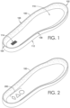
- FIG. 1 depicts an exemplary sole 100 having a toe end 102, a heel end 104, a medial side 108, and a lateral side 106, in accordance with aspects hereof.
- the sole 100 also has a foot-facing surface 110 and a ground-facing surface.
- the sole 100 is comprised of a lip or side wall extending around one or more portions. At the superior edge of the sidewall, as will be discussed in FIG. 5 hereinafter, a biteline may be identified on a mated upper.
- the identifier 114 is a structure that is identifiable for the identification of the sole 100.
- a variety of technologies may be implemented as the identifier 114, which is generically depicted for illustration purposes herein.
- the identifier 114 may be a radio frequency identification (RFID) technology.
- RFID radio frequency identification
- the RFID technology may be either passive or active.
- an RFID tag may respond to the application of electromagnetic energy, such as a radio signal, that causes the RFID tag to transmit a signal.
- the signal may be a unique identifier that is received by a receiver tuned to a frequency at which the RFID tag transmits.
- An active RFID tag may periodically provide a signal in an unsolicited manner in the event a receiver is within range to detect the signal.
- An RFID may be read only or it may be rewritable such that a unique signature may be programmed to the RFID, in an aspect hereof.
- the identifier 114 may be based on any or a number of technologies that allow for the identification of the identifier 114 relative to one or more other identifiers.
- the identifier 114 is depicted in a heel region of the sole 100 on the foot-facing surface 110, it is contemplated that the identifier 114 may be positioned or placed at any location.
- the identifier 114 is embedded within the sole 100, positioned at a toe region, positioned at a ground-facing surface, at an arch region between the toe and heel end, or elsewhere on the sole.
- the identifier 114 is positioned on or near the foot-facing surface 110 such that the identifier 114 is obscured by an upper following a mating operation. This obscuring of the identifier 114 prevents the identifier 114 from being visible on a finished shoe.
- the location of the identifier 114 which may be permanent to the article resulting in a sacrificial identifier, may be selected based on the technology on which the identifier is based, on the location that limits adverse effects to the finished shoe, or on other factors.
- FIG. 2 depicts the sole 100 having an alternative identifier 200, in accordance with aspects hereof.
- the identifier 200 may be based on a technology in which a detectable material is deposited on the sole 100.
- a detectable material is deposited on the sole 100.
- an ink-like material that is detectible as a result of one or more electromagnetic energy sources applying energy thereto are printed on the sole 100 in a particular manner.
- the ink may be a polyurethane-based material having one or more electrically responsive materials (e.g., metallic, carbon, etc.) contained therein is printed in a pattern on the article.
- the pattern may be optically detected (e.g., by way of a camera, or electrically detected based on a signal output as a result of exposure to electromagnetic radiation.
- the identifier 200 is formed as a series of shapes, such as a diamond, triangle, and circle. This pattern provides a unique signature when optically or electrically detected. The unique signature may be used to assign a unique identity to the sole 100. It is contemplated that any pattern, lettering, shapes, lines, and the like may be implemented in any combination or any order to achieve a unique signature, in exemplary aspects.
- FIG. 3 depicts a last 300, in accordance with aspects hereof.
- a last is a tool about which an upper is formed. The last may also serve as a tool for mating the upper with a sole as it provides resistance to pressure applied when mating the sole to the upper.
- the last 300 has a toe end 304, a heel end 306, a sole-facing surface 308, a superior surface 310, and an exposed portion 302.
- the exposed portion 302 is a portion of the last 300 that is not obscured by an upper, such as the contextually provided upper 314, when the upper is lasted about the last 300.
- the last comprises an identifier 312. As depicted in FIG. 3 , the identifier 312 is provided in the exposed portion 302, which will be discussed hereinafter.
- the identifier 312 may be any type of identifier, such as those discussed in connection with the identifier 114 of FIG. 1 .
- the identifier 312 is an RFID-based identifier.
- other technologies may be used as an identifier of the last 300. It is contemplated that the last 300 uses a first identifier technology and a sole uses a different identifier technology, in an exemplary aspect. In alternative aspects, the last 300 and a sole use a similar identifier technology. The last 300 may be used in connection with a number of different uppers 314. Therefore, the identifier 312 may be reused in the manufacturing processes as the last 300 is reused following the completion of a shoe.
- the identifier 312 may be based on a technology that is more costly than the identifier used in connection with a sole, as the identifier used with a sole may stay with the sole following production and be sacrificed. Stated differently, a first identifier type may be used with the tooling that remains in the manufacturing system while a second, different, identifier type may be used with the components being manufactured that will leave the manufacturing system upon completion of the manufacturing with that component.
- the location of the identifier 312 relative to the last 300 may be selected based on the technology of the identifier, the manufacturing processes being performed, or other factors. For example, it is contemplated that holding element, such as a robotic arm, may grasp the last 300 (or a portion affixed thereto as will be illustrated in FIG. 4 hereinafter) during a manufacturing process. Therefore, the identifier 312 may be positioned on the last 300 in a location that does not interfere with or is obscured by the material movement mechanisms manipulating the last 300. The avoidance of interference or obscuring may allow for easier or more accurate identification of the identifier 312, in an exemplary aspect. Further, it is contemplated that the identifier 312 may be on a surface, embedded therein, or a combination relative to the last 300 (or structures affixed thereto), in an exemplary aspect.
- FIG. 4 depicts the last 300 having an extension 400 affixed thereto, in accordance with aspects hereof.
- the last extension 400 is affixed to the superior surface 310.
- the last extension 400 has the identifier 312 associated therewith.
- a last extension 400 may be affixed to the last 300 to allow for the integration of the identifier 312 with an existing inventory of lasts. Additionally, the last extension 400 may provide a greater clearance from the upper and other tooling to provide for easier identification, in an exemplary aspect. Further yet, the last extension 400 may be affixed, temporarily or permanently, with the last 300 to facilitate automated manufacturing processes while still utilizing an existing inventory of lasts, in an exemplary aspect.
- the location of the identifier on the last extension 400 may be selected for the reasons provided above with connection the FIG. 3 , in exemplary aspects. It is contemplated that an identifier associated with a last extension is therefore associated with the last to which the last extension is affixed, in an exemplary aspect.
- FIG. 5 depicts an exemplary system 500 for associating the last 300 with the sole 100 based on unique identifiers associated with each, in accordance with aspects hereof.
- an image or surface mapping is further associated with the sole 100, the last 300, and/or a combination thereof.
- the image or surface mapping may be captured, in part with a camera 502, as will be discussed hereinafter.
- a computing device 508 having a central processing unit and memory is depicted being coupled with a first sensor 504, a second sensor 506, and the camera 502.
- one or more of the sensors and/or camera are optional and merely provided for illustrative purposes.
- the first sensor 504 is a sensor for detecting and identifying the identifier 312 of the last 300.
- the sensor 506 is a sensor for detecting and identifying an identifier 114 of the sole 100. It is contemplated that a single sensor may detect both the identifier 312 and 114, in an exemplary aspect. Further, it is contemplated that the first sensor 504 relies on a different technology than the second sensor 506, in an exemplary aspect.
- a sensor may leverage a variety of technology. For example, in connection with an RFID identifier, the sensor may include both am electromagnetic energy (e.g., radio waves) transmitter and a receiver.
- the senor may output radio waves that are then converted into energy by an identifier to transmit a signature back to the sensor, which is received by a receiving device in the sensor.
- the identifier may broadcast a signal having a signature that is then received by a sensor.
- a sensor may be an energy transmitter that broadcasts energy that is then refracted and/or reflected by one or more elements of the identifier.
- the sensor may have a receiving device capable of detecting and interpreting the reflected and/or refracted energy to determine a signature for the identifier, in an exemplary aspect.
- a sensor is an imaging device that operates in one or more wavelengths, such as visible light spectrum, infrared light spectrum, ultraviolet light spectrum, and/or x-ray spectrum.
- the sensor is comprised of a detection mechanism for detecting energy in the selected wave lengths.
- the imaging device may be comprised of an energy emitter, such as a light source in one or more spectrums. Therefore, it is contemplated that a sensor may implement a variety of technologies compatible with a provided identifier to detect and identify a unique identifier/signature of an identifier, such as the identifier 312 and/or 114.
- the camera 502 may be utilized to detect a biteline 510 that is formed at the intersection of the sole 100 and the upper.
- a biteline may represent a location up to which adhesive or other bonding agents may be applied between the upper and the sole. If the adhesive extends above the biteline, the adhesive will be exposed on a surface of the upper and not obscured by the sole. Further, if the adhesive fails to be applied up to the biteline, the sole may be prone to separation from the upper at that location.
- the lasted upper on the last 300 may be temporarily mated with the sole 100 to allow a detection of the biteline 510.
- the biteline 510 may be determined by analyzing one or more images captured by the camera 502.
- the computing device 508 may generate a multi-dimensional mapping based on the images captured by one or more cameras 502. This mapping may be associated, within a computing environment, with the identifier 312 and/or 114 for future use, such as determining a tool path for application of adhesive on the upper lasted to the last 300, in an exemplary aspect.
- An association between the identifier 312 and the identifier 114 may be maintained at the computing device 508, in an exemplary aspect.
- the sensor 504 may identify the identifier 312 and the sensor 506 may identify the identifier 114 during biteline detection.
- the upper lasted on the last 300 having the identifier 312 is associated with the sole 100 having the identifier 114. Therefore, following one or more processes performed to each of the individual components (e.g., the upper lasted on the last 300 and the sole 100), a verification can be performed that the upper lasted on the last 300 is re-mated with the sole 100 such that the previously detected and mapped biteline 510 is maintained.
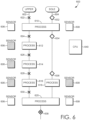
- FIGS. 6 and 7 illustrate exemplary manufacturing systems 600 leveraging sensors 606 and 608 to detect identifiers associated with the upper and the sole, respectively, in accordance with aspects hereof.
- the system 600 includes a plurality of processes being performed to individual components, such that the components may be tracked during their progression through the system 600 on independent manufacturing lines. The individual components may then be paired in the system 600 with confidence that a proper first component and an intended second component are mated within the system 600.
- the system 600 is comprised of a first material handling device 602 and a second material handling device 604. Additional material handling devices are contemplated.
- a material handling device may be a mechanism for transporting a component, such as a component used in the formation of a shoe between manufacturing processes.
- a conveyance system like a conveyor belt, a robotic material handler, and the like are examples of material handling devices.
- the system 600 is also comprised of a first sensor 606.
- the first sensor 606 relies on a technology useable for identifying components on the material handling device 602, such as lasts. As provided above, it is contemplated that the sensor 606 is an RFID reader capable of detecting and identifying RFID tags associated with a last have an upper lasted thereon passing along the material handling device 602, in an exemplary aspect.
- the number of sensor 606 that are part of the system 600 is optional, as depicted by the shaded sensor 606 associated with several processes. Therefore, any number of sensors 606 at any location of the system 600 is contemplated.
- the second sensor 608 on a technology useable for identifying components on the material handling device 604, such as a sole.
- the sensor 608 may be a sensor capable of detecting and identifying RFID, optical, doped substances, images, and the like. It is contemplated that any number of sensors 608 may be implemented at any location of the system 600, as illustrated with the shaded sensor 608, for example.
- the system 600 is further comprised of a computing device 640 having a processor and memory.
- the computing device 640 may be functionally in communication with the sensor 606, sensor 608, and one or more machines/devices used at one or more processes.
- the computing device 640 may maintain an association between a first identifier and a second identifier, as previously discussed, to allow for and ensure a proper re-mating of two or more components, in an exemplary aspect.
- the system 600 is also comprised of one or more processes, such as processes 610, 612, 614, 616, 618, and 620.
- the system 600 is also comprised of a number of components, such as components 622, 624, 626, 628, 630, 632, 634, 636, and 638.
- the components may be items onto which a manufacturing process is performed at one of the processes.
- the components 622, 624, 626, 628, and 630 may be uppers
- the components 632, 634, and 636 may be soles
- the component 638 may be a mating of multiple components, such as an upper and a sole, in an exemplary aspect.
- the process 610 may be any processes.
- the process 610 is a process that involves an upper and a sole, such as biteline detection.
- an upper and a sole are temporarily mated to detect the biteline.
- the sensor 606 identifies a particular upper (or a last having the upper thereon) and the sensor 608 identifies a sole.
- the identified upper and sole may be associated for future re-mating, such as at the process 620.
- each of the components may remain on a respective material handling device for further operations.
- the process 612 may include a dryer for the upper, a printing step for the upper, a trimming step for the upper, a priming step for the upper, and the like.
- the processes 614 and 616 may include any manufacturing processes as well.
- the process 618 may be any manufacturing process to a sole, such as drying, priming, applying adhesive, trimming, printing, and the like.
- one or more components may be damaged, moved, re-ordered, removed, or other scenarios that may limit the ability to merely count a number of components passing through the system 600 to determine an appropriate mate at a subsequent process, in an exemplary aspect. Therefore, the identifiers for each component are useable for determining and ensuring an association of intended components.
- the process 620 includes the mating of a sole and an upper to result in the combined component 638. It is contemplated that the sensor 606 at process 620 identifies the upper being processed and the sensor 608 at the process 620 identifies the sole being processed to ensure the correct components will be mated for the previous operations performed to each (e.g., adhesive applied to a particular location based on a detected biteline of the specific combination of the sole and upper).
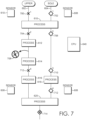
- FIG. 7 depicts the system 600 where the identification of components will be advantageous over a mere counting of components, in accordance with aspects hereof.
- the material handling device 602 has components 700, 704, and 712.
- a component 708 is depicted as being removed from the queue of the first material handling device 602.
- the component 708 may have been damaged, misplaced, removed, or otherwise altered from the position in the queue of components on the first material handling device 602.
- the second material handling device 604 has components 702, 706, 710, and 714.
- components 700 and 702, 704 and 706, 708 and 710, 712 and 714 are associated with each other respectively.
- component 708 that was to be re-mated with component 710 could result in component 710 instead being mated with component 704, in this example.
- component 708 and 704 may have enough dimensional difference that the re-mating of these unintended components may result in un-desired aesthetic and/or functional pairing.
- a detection of the identifiers of component 710 and 704 will allow for a determination that those two components were not originally associated together. Therefore, once two components are mated, such as component 716, there is a confidence that the intended components were re-mated at the previous process, in this example.
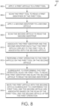
- FIG. 8 depicts flow diagram 800 representing a method of tracking a first article/component and a second article/component in a manufacturing system, in accordance with aspects hereof.
- a step of applying a first article to a first tool is provided.
- the first article may be an upper and the upper may be applied to a last, which may be the first tool.
- a step of scanning the first tool to read a first identifier of the first tool is provided.
- the scanning of the identifier may be performed by a sensor having technology capable of identifying a signature from the identifier of the first tool.
- first article being associated with an identifier of a first tool
- first article such as an upper
- first article has an identifier applied directly to the first article, in an exemplary aspect. Therefore, the identification of a particular tooling may be omitted in this example.
- a step of applying a second identifier to a second article is provided.
- an identifier is applied to a sole.
- a step of scanning the second article to read the second identifier is provided.
- the scanning may be performed by a sensor adapted to detect an identity of the identifier. Therefore, when scanning to read the identifier, a signature of the identifier is determined.
- a step of associating the first identifier with the second identifier is provided. The association of the two identifiers allows for an association to be made between the first article on the first tool with the second article, in the provided aspect.
- a step of performing a first operation to either the first article or the second article is provided.
- the operation may be any processes, such as applying an adhesive to a sole and/or an upper. Because the operation may be performed based on a specific combination of the first article and the second article, such as complying with a unique biteline between the first and second articles, the first operation may be unique to the combination of the first and second articles.
- a step of scanning the first tool to read the first identifier and scanning the second article to read the second identifier is performed after the first operation has completed. For example, subsequent to applying adhesive to the sole and/or the upper, the sole and the last maintaining the upper are identified to ensure an appropriate re-mating between the two article/components may occur.
- a step of mating the first article with the second article subsequent to confirming the first tool and the second tool are associated based on the scanning of the first tool and the second article after the first operation is performed.
- the sole and the upper are mated.
- the first tool may then be used for a third article.
- another upper may be lasted on the first tool. Therefore, the identifier of the last may be recycled in the system for the new upper. This may reduce costs associated with aspects of the system as the identifier may be maintained in the system with the tooling as opposed to being sacrificed with the completion of an article with which the identifier is associated.
- a tracking system such as that which is provided herein, utilizes one or more sensors to identify a right shoe portion and a left shoe portion that are then associated together for eventual re-pairing following one or more manufacturing processes. For example, if each of the right shoe portion and the left shoe portion are customized relative to other shoe portions undergoing one or more manufacturing processes in a common system, it may be desired to ensure the corresponding right shoe portion and the left shoe portion are matched together following the manufacturing process so that the unique customization to each is maintained together, in an exemplary aspect.
- an appropriate right shoe and an appropriate left shoe may be paired for packing and/or shipping utilizing aspects contemplated herein, in an exemplary aspect.
Landscapes
- Engineering & Computer Science (AREA)
- Business, Economics & Management (AREA)
- Human Resources & Organizations (AREA)
- Physics & Mathematics (AREA)
- General Physics & Mathematics (AREA)
- Economics (AREA)
- Strategic Management (AREA)
- Theoretical Computer Science (AREA)
- Manufacturing & Machinery (AREA)
- Quality & Reliability (AREA)
- General Business, Economics & Management (AREA)
- Tourism & Hospitality (AREA)
- Entrepreneurship & Innovation (AREA)
- Marketing (AREA)
- General Engineering & Computer Science (AREA)
- Automation & Control Theory (AREA)
- Development Economics (AREA)
- Operations Research (AREA)
- Educational Administration (AREA)
- Game Theory and Decision Science (AREA)
- Health & Medical Sciences (AREA)
- General Health & Medical Sciences (AREA)
- Primary Health Care (AREA)
- Microelectronics & Electronic Packaging (AREA)
- Footwear And Its Accessory, Manufacturing Method And Apparatuses (AREA)
Claims (12)
- Ein Produktionsverfolgungssystem (500, 600) für ein Verfahren zur Herstellung eines Fußbekleidungsartikels, wobei das System Folgendes umfasst:ein Werkzeug (300, 602) mit einer ersten Kennung (312),wobei das Werkzeug (300, 602) konfiguriert ist, um einen ersten Artikel (314, 622) aufzunehmen,und wobei das Werkzeug (300, 602) ein Schuhwerks-Leisten (300, 602) ist und der erste Artikel (314, 622) ein Oberteil (314, 622) ist;einen ersten Sensor eines ersten Sensortyps (504, 606),
wobei der erste Sensor des ersten Sensortyps (504, 606) konfiguriert ist, um die erste Kennung (312) zu lesen;eine zweite Kennung (114), die mit einem zweiten Artikel (100, 604) gekoppelt ist,
wobei der zweite Artikel (100, 604) eine Sohle (100, 604) ist;einen ersten Sensor eines zweiten Sensortyps (506, 608),
wobei der erste Sensor des zweiten Sensortyps (506, 608) so konfiguriert ist, dass er die zweite Kennung (114) liest;ein Rechensystem (508, 640) mit einem Prozessor und einem Speicher, das konfiguriert ist, um die erste Kennung (312) mi der zweiten Kennung (114) zu verknüpfen, wobei das Verknüpfen der ersten Kennung (314) mit der zweiten Kennung (114) durch das Rechensystem (508, 640) erfolgt, bevor das Oberteil (314, 622) separat und unabhängig von der Sohle (100, 604) verarbeitet wird und die Sohle (100, 604) separat und unabhängig vom Oberteil (314, 622) verarbeitet wird;eine erste Bearbeitungsstation zur Bearbeitung des Oberteils (314, 622) separat und unabhängig von der Sohle (100, 604);eine zweite Bearbeitungsstation zur Bearbeitung der Sohle (100, 604) separat und unabhängig vom Oberteil (314, 622);einen zweiten Sensor des ersten Sensortyps (606), der konfiguriert ist, um nach der ersten Bearbeitungsstation die erste Kennung (312) zu lesen;einen zweiten Sensor des zweiten Sensortyps (608), der konfiguriert ist, um nach der zweiten Verarbeitungsstation die zweite Kennung (114) zu lesen;eine dritte Verarbeitungsstation,wobei die dritte Verarbeitungsstation konfiguriert ist, um das Oberteil (314, 622) auf dem Schuhwerks-Leisten (300, 602) mit der Sohle (100, 604) zusammenzufügen, teilweise auf der Grundlage, dass der zweite Sensor des ersten Sensortyps (606) den Schuhwerks-Leisten (300, 602) liest, und dass der zweite Sensor des zweiten Sensortyps (606) der Sohle (100, 604) liest,wobei das Computersystem (508, 640) ferner konfiguriert ist, um zu bestätigen, dass der Schuhwerks-Leisten (300, 602) und die Sohle (100, 604) auf der Grundlage des zweiten Sensors des ersten Sensortyps (606) und des zweiten Sensors des zweiten Sensortyps (608) zusammengefügt werden sollen,wobei der zweite Sensortyp eine Kennung mit einer anderen Technologie als der erste Sensortyp liest,wobei vor dem Verknüpfen der ersten Kennung (314) mit der zweiten Kennung (114) durch das Computersystem (508, 640) das Oberteil (314, 622) und die Sohle (100, 604) vorübergehend zusammengefügt werden, um einen Schnittpunkt zwischen dem Oberteil (314, 622) und der Sohle (100, 604) zu identifizieren,wobei während des vorübergehenden Zusammenfügens des Oberteils (314, 622) und der Sohle (100, 604) der erste Sensor des ersten Sensortyps (504, 606) den Schuhwerks-Leisten (300, 602) mit dem Oberteil (314, 622) identifiziert, und der erste Sensor des zweiten Sensortyps (506, 608) die Sohle (100, 604) identifiziert. - Das System nach Anspruch 1, wobei die erste Kennung (312) ein RFID-Tag (Radio Frequency Identification) ist.
- Das System nach Anspruch 2, wobei der RFID-Tag wiederbeschreibbar ist.
- Das System nach irgendeinem der Ansprüche von 1 bis 3, wobei die erste Kennung (312) zumindest teilweise im Schuhwerks-Leisten (300, 602) eingebettet ist; oder,
wobei die erste Kennung (312) am Schuhwerks-Leisten (300, 602) an einer Stelle positioniert ist, die durch das Oberteil (314, 622) am Schuhwerks-Leisten (300, 602) nicht verdeckt wird - Das System nach Anspruch 1, wobei der erste Sensortyp eine Funkfrequenz-Empfangsvorrichtung umfasst.
- Das System nach Anspruch 1, wobei der zweite Sensortyp eine Funkempfangsvorrichtung umfasst.
- Das System nach irgendeinem der Ansprüche von 1 bis 2, wobei der zweite Sensortyp eine Bilderfassungsvorrichtung umfasst.
- Das System nach Anspruch 1, wobei die erste Verarbeitungsstation eine Klebstoffauftragsstation ist, die zum Auftragen eines Klebstoffs auf das Oberteil (314, 622) konfiguriert ist, und wobei die zweite Verarbeitungsstation eine Klebstoffauftragsstation ist, die zum Auftragen eines Klebstoffs auf die Sohle (100, 604) konfiguriert ist; oder,
wobei eine erste Materialhandhabungsvorrichtung das Oberteil (314, 622) zur ersten Bearbeitungsstation transportiert, und wobei eine zweite Materialhandhabungsvorrichtung die Sohle (100, 604) zur zweiten Bearbeitungsstation transportiert. - Ein Verfahren zum Verfolgen eines ersten Artikels (314, 622) und eines zweiten Artikels (100, 604) in einem Produktionssystem zur Herstellung eines Fußbekleidungsartikels, wobei das Verfahren Folgendes umfasst:Aufbringen (802) des ersten Artikels (314, 622) auf ein Werkzeug (300, 602),
wobei das Werkzeug (300, 602) ein Schuhwerks-Leisten (300, 602) ist und der erste Artikel (314, 622) ein Oberteil (314, 622) ist;Abtasten (804), durch einen ersten Sensor eines ersten Sensortyps (504, 606), des Schuhwerks-Leistens (300, 602), um eine erste Kennung (312) des Schuhwerks-Leistens (300, 602) zu lesen;Aufbringen (806) einer zweiten Kennung (114) auf den zweiten Artikel (100, 604),
wobei der zweite Artikel (100, 604) eine Sohle (100, 604) ist;Abtasten (808), durch einen ersten Sensor eines zweiten Sensortyps (506, 608), der Sohle (100, 604), um die zweite Kennung (114) zu lesen;Verknüpfen (810), durch ein Computersystem (508, 640) mit einem Prozessor und einem Speicher, der ersten Kennung (312) mit der zweiten Kennung (114) sodass das Obermaterial (314, 622), das auf dem Schuhwerks-Leisten (300, 602) aufgebracht ist, der Sohle (100, 604) zugeordnet werden kann,nach dem Verknüpfen (810) der ersten Kennung (312) mit der zweiten Kennung (114), Durchführen (812) eines ersten Verarbeitungsvorgangs am Obermaterial (314, 622) auf dem Schuhwerks-Leisten (300, 602) und zwar separat und unabhängig von der Sohle (100, 604), oder an der Sohle (100, 604) separat und unabhängig vom Obermaterial (300, 602);nach dem Durchführen des ersten Verarbeitungsvorgangs, Abtasten (814), durch einen zweiten Sensor des ersten Sensortyps (606), des Schuhwerks-Leistens (300, 602) zum Lesen der ersten Kennung (312), und Abtasten (814), durch einen zweiten Sensor des zweiten Sensortyps (608), der Sohle (100, 604) zum Lesen der zweiten Kennung (114);Zusammenfügen (620; 816) des Oberteils (314, 622) mit der Sohle (100, 604) nach dem Bestätigen durch das Computersystem (508, 640), dass der Schuhwerks-Leisten (300, 602) und die Sohle (100, 604) einander zugeordnet sind, auf der Grundlage der Abtastung des Schuhwerks-Leistens (300, 602) und der Sohle (100, 604) nach dem ersten Verarbeitungsvorgang,wobei die erste Kennung (312) mit einer anderen Technologie als die zweite Kennung (114) gescannt wird,wobei vor dem Verknüpfen (810) der ersten Kennung (314) mit der zweiten Kennung (114) durch das Rechensystem (508, 640), das Oberteil (314, 622) und die Sohle (100, 604) vorübergehend zusammengefügt werden, um einen Schnittpunkt zwischen dem Oberteil (314, 622) und der Sohle (100, 604) zu identifizieren,wobei, während des vorübergehenden Zusammenfügens des Oberteils (314, 622) und der Sohle (100, 604), der erste Sensor des ersten Sensortyps (504, 606) den Schuhwerks-Leisten (300, 602) mit dem Oberteil (314, 622) identifiziert, und wobei der erste Sensor des zweiten Sensortyps (506, 608) die Sohle (100, 604) identifiziert. - Das Verfahren nach Anspruch 9, das ferner Folgendes umfasst:
Entfernen des Oberteils (314, 622) vom Schuhwerks-Leisten (300, 602) nach dem Zusammenfügen des Oberteils (314, 622) mit der Sohle (100, 604):Aufbringen eines weiteren Oberteils (624) auf den Schuhwerks-Leisten (300, 602);Abtasten des Schuhwerks-Leistens (300, 602), um die erste Kennung (312) zu lesen;Anbringen einer dritten Kennung an einer weiteren Sohle (634); undVerknüpfen der ersten Kennung (312) mit der dritten Kennung, sodass das weitere Obermaterial (624), das auf dem Schuhwerks-Leisten (300, 602) angebracht ist, der weiteren Sohle (634) zugeordnet wird. - Das Verfahren nach Anspruch 9 oder 10, wobei das Abtasten der ersten Kennung (312) das Empfangen eines Signals von der ersten Kennung (312) umfasst; oder,wobei die erste Kennung (312) ein RFID-Identifikator (Radio-Frequency Identification) ist; oder,wobei das Anbringen der zweiten Kennung (114) an der Sohle (100, 604) das Aufkleben der zweiten Kennung (114) auf einen Abschnitt der Sohle (100, 604) umfasst.
- Das Verfahren nach irgendeinem der Ansprüche von 9 bis 11, wobei der erste Vorgang das Aufbringen eines Klebstoffs auf eine Oberfläche des mit der Sohle (100, 604) zusammenzufügenden Oberteils (314, 622) umfasst; oder,
wobei das Zusammenfügen des Oberteils (314, 622) mit der Sohle (100, 604) die zweite Kennung (114) auf der Sohle (100, 604) bedeckt, sodass die zweite Kennung (114) zwischen dem Oberteil (314, 622) und der Sohle (100, 604) positioniert ist.
Applications Claiming Priority (2)
| Application Number | Priority Date | Filing Date | Title |
|---|---|---|---|
| US201562167732P | 2015-05-28 | 2015-05-28 | |
| PCT/US2016/034159 WO2016191491A1 (en) | 2015-05-28 | 2016-05-25 | Assembly line article tracking system |
Publications (2)
| Publication Number | Publication Date |
|---|---|
| EP3304483A1 EP3304483A1 (de) | 2018-04-11 |
| EP3304483B1 true EP3304483B1 (de) | 2024-11-06 |
Family
ID=56203908
Family Applications (1)
| Application Number | Title | Priority Date | Filing Date |
|---|---|---|---|
| EP16732025.8A Active EP3304483B1 (de) | 2015-05-28 | 2016-05-25 | Artikelverfolgungssystem einer montagelinie |
Country Status (7)
| Country | Link |
|---|---|
| US (2) | US20170308066A1 (de) |
| EP (1) | EP3304483B1 (de) |
| KR (1) | KR102010689B1 (de) |
| CN (2) | CN205848878U (de) |
| MX (1) | MX2017015059A (de) |
| TW (3) | TWI699635B (de) |
| WO (1) | WO2016191491A1 (de) |
Families Citing this family (16)
| Publication number | Priority date | Publication date | Assignee | Title |
|---|---|---|---|---|
| US10852069B2 (en) | 2010-05-04 | 2020-12-01 | Fractal Heatsink Technologies, LLC | System and method for maintaining efficiency of a fractal heat sink |
| US10552551B2 (en) | 2011-11-18 | 2020-02-04 | Nike, Inc. | Generation of tool paths for shore assembly |
| US9451810B2 (en) | 2011-11-18 | 2016-09-27 | Nike, Inc. | Automated identification of shoe parts |
| US8755925B2 (en) | 2011-11-18 | 2014-06-17 | Nike, Inc. | Automated identification and assembly of shoe parts |
| US8958901B2 (en) | 2011-11-18 | 2015-02-17 | Nike, Inc. | Automated manufacturing of shoe parts |
| US8849620B2 (en) | 2011-11-18 | 2014-09-30 | Nike, Inc. | Automated 3-D modeling of shoe parts |
| TWI699635B (zh) | 2015-05-28 | 2020-07-21 | 荷蘭商耐克創新有限合夥公司 | 製造追蹤系統 |
| WO2021034784A1 (en) | 2019-08-16 | 2021-02-25 | Poltorak Technologies, LLC | Device and method for medical diagnostics |
| WO2021084690A1 (ja) * | 2019-10-31 | 2021-05-06 | 日本電気株式会社 | 情報処理システム、情報処理装置、インソール、情報処理方法および記録媒体 |
| KR102897017B1 (ko) * | 2019-12-09 | 2025-12-08 | 나이키 이노베이트 씨.브이. | 디지털 핑거프린팅 |
| CN112293871B (zh) * | 2020-09-09 | 2022-03-22 | 中国皮革和制鞋工业研究院温州研究所 | 一种制鞋流水线 |
| KR102555311B1 (ko) * | 2020-11-09 | 2023-07-14 | 삼덕통상 주식회사 | 신발 부재의 자동화 제조시스템 |
| DK181424B1 (en) * | 2021-06-23 | 2023-11-13 | Ecco Sko As | A footwear manufacturing system and method |
| CN114098232B (zh) * | 2021-10-29 | 2023-04-11 | 丽荣鞋业(深圳)有限公司 | 铁板烧和换模一体设备 |
| WO2024069372A1 (en) * | 2022-09-26 | 2024-04-04 | Puma SE | Article of footwear having a modular plate system |
| WO2026002355A1 (en) * | 2024-06-27 | 2026-01-02 | Ecco Sko A/S | Footwear characteristics evaluation method and system |
Citations (5)
| Publication number | Priority date | Publication date | Assignee | Title |
|---|---|---|---|---|
| KR20080040360A (ko) * | 2006-11-03 | 2008-05-08 | 강영균 | 알에프아이디를 이용한 신발의 생산능력 분석, 추적 및최적투입 지시 시스템 |
| CN101286061A (zh) * | 2008-04-08 | 2008-10-15 | 浙江理工大学 | 一种信息驱动的皮鞋制造方法 |
| CN103099390A (zh) * | 2013-01-14 | 2013-05-15 | 东莞市意利自动化科技有限公司 | 一种集成rfid的鞋子生产方法及专用鞋楦连接件 |
| US20130131854A1 (en) * | 2011-11-18 | 2013-05-23 | Nike, Inc. | Automated Identification And Assembly Of Shoe Parts |
| US20130125319A1 (en) * | 2011-11-18 | 2013-05-23 | Nike, Inc. | Automated Manufacturing Of Shoe Parts |
Family Cites Families (19)
| Publication number | Priority date | Publication date | Assignee | Title |
|---|---|---|---|---|
| US4377890A (en) * | 1979-05-21 | 1983-03-29 | Rca Corporation | Method of CRT manufacture using machine readable coded markings |
| US4741062A (en) * | 1985-09-06 | 1988-05-03 | Roger Blanc | Last for automated shoe manufacture |
| GB8724904D0 (en) * | 1987-10-23 | 1987-11-25 | Clark Ltd C & J | Lasts for footwear |
| MXPA02010342A (es) * | 2000-04-20 | 2004-09-06 | Cogiscan Inc | Sistema automatizado de control de manufactura. |
| JP2003233652A (ja) * | 2002-02-12 | 2003-08-22 | Sharp Corp | 品質管理システム、品質管理方法、品質管理プログラム及び品質管理プログラムを記録した記録媒体 |
| US9569746B2 (en) * | 2002-03-14 | 2017-02-14 | Nike, Inc. | Custom fit sale of footwear |
| AT502890B1 (de) * | 2002-10-15 | 2011-04-15 | Atomic Austria Gmbh | Elektronisches überwachungssystem zur kontrolle bzw. erfassung einer aus mehreren sportartikeln bestehenden sportartikelkombination |
| US20060143839A1 (en) * | 2003-02-20 | 2006-07-06 | Thomas Fromme | Method for producing made-to-measure orthopaedic shoes |
| US7411500B2 (en) | 2005-09-14 | 2008-08-12 | 3M Innovative Properties Company | Methods of monitoring items or material from manufacturing processes |
| EP2257414A4 (de) * | 2008-02-28 | 2012-12-26 | Ontario Die Internat Inc | Systeme und verfahren zur echtzeitüberwachung der chipverwendung oder des ertrages |
| US9107480B2 (en) * | 2008-10-25 | 2015-08-18 | Dynasty Footwear, Ltd. | Shoe having securely printed tab |
| WO2011159338A1 (en) | 2010-06-14 | 2011-12-22 | Trutag Technologies, Inc. | System for verifying an item in a package |
| US9082062B2 (en) * | 2011-10-10 | 2015-07-14 | Zortag, Inc. | Method of, and system and label for, authenticating objects in situ |
| US9451810B2 (en) * | 2011-11-18 | 2016-09-27 | Nike, Inc. | Automated identification of shoe parts |
| US9036337B2 (en) * | 2012-04-10 | 2015-05-19 | Psion Inc. | Protective enclosure for an electronic device |
| US9173453B2 (en) * | 2012-12-21 | 2015-11-03 | Ebay, Inc. | Methods and systems to re-create an internal shape of a shoe |
| DE102013221020B4 (de) * | 2013-10-16 | 2020-04-02 | Adidas Ag | Speedfactory 3D |
| CN103732004A (zh) | 2013-12-31 | 2014-04-16 | 苏州思莱特电子科技有限公司 | 一种电板固定架 |
| TWI699635B (zh) | 2015-05-28 | 2020-07-21 | 荷蘭商耐克創新有限合夥公司 | 製造追蹤系統 |
-
2016
- 2016-05-05 TW TW108101963A patent/TWI699635B/zh not_active IP Right Cessation
- 2016-05-05 TW TW105206391U patent/TWM535485U/zh unknown
- 2016-05-05 TW TW105113894A patent/TWI654506B/zh active
- 2016-05-25 KR KR1020177037254A patent/KR102010689B1/ko active Active
- 2016-05-25 US US15/509,093 patent/US20170308066A1/en not_active Abandoned
- 2016-05-25 MX MX2017015059A patent/MX2017015059A/es unknown
- 2016-05-25 WO PCT/US2016/034159 patent/WO2016191491A1/en not_active Ceased
- 2016-05-25 EP EP16732025.8A patent/EP3304483B1/de active Active
- 2016-05-27 CN CN201620502578.1U patent/CN205848878U/zh not_active Expired - Fee Related
- 2016-05-27 CN CN201610365450.XA patent/CN106174905B/zh active Active
-
2020
- 2020-02-18 US US16/793,980 patent/US10962964B2/en active Active
Patent Citations (5)
| Publication number | Priority date | Publication date | Assignee | Title |
|---|---|---|---|---|
| KR20080040360A (ko) * | 2006-11-03 | 2008-05-08 | 강영균 | 알에프아이디를 이용한 신발의 생산능력 분석, 추적 및최적투입 지시 시스템 |
| CN101286061A (zh) * | 2008-04-08 | 2008-10-15 | 浙江理工大学 | 一种信息驱动的皮鞋制造方法 |
| US20130131854A1 (en) * | 2011-11-18 | 2013-05-23 | Nike, Inc. | Automated Identification And Assembly Of Shoe Parts |
| US20130125319A1 (en) * | 2011-11-18 | 2013-05-23 | Nike, Inc. | Automated Manufacturing Of Shoe Parts |
| CN103099390A (zh) * | 2013-01-14 | 2013-05-15 | 东莞市意利自动化科技有限公司 | 一种集成rfid的鞋子生产方法及专用鞋楦连接件 |
Also Published As
| Publication number | Publication date |
|---|---|
| TWI699635B (zh) | 2020-07-21 |
| TW201702779A (zh) | 2017-01-16 |
| TW201928557A (zh) | 2019-07-16 |
| US20170308066A1 (en) | 2017-10-26 |
| US20200183366A1 (en) | 2020-06-11 |
| TWI654506B (zh) | 2019-03-21 |
| KR20180011816A (ko) | 2018-02-02 |
| MX2017015059A (es) | 2018-05-17 |
| TWM535485U (zh) | 2017-01-21 |
| KR102010689B1 (ko) | 2019-08-13 |
| CN106174905A (zh) | 2016-12-07 |
| WO2016191491A1 (en) | 2016-12-01 |
| CN205848878U (zh) | 2017-01-04 |
| US10962964B2 (en) | 2021-03-30 |
| CN106174905B (zh) | 2020-06-30 |
| EP3304483A1 (de) | 2018-04-11 |
Similar Documents
| Publication | Publication Date | Title |
|---|---|---|
| US10962964B2 (en) | Assembly line article tracking system | |
| WO2015143663A1 (zh) | 鞋底与鞋面粘合标线的三维测量系统及其三维测量方法 | |
| US20170272728A1 (en) | System and method of three-dimensional scanning for customizing footwear | |
| US20190139252A1 (en) | Systems and methods for footwear sizing | |
| TWI622363B (zh) | 產生用於鞋類之虛擬咬合線的系統與處理鞋面的方法 | |
| EP3462966B1 (de) | Schuhwerksherstellung mit verschachteltem oberschuh mit flachem muster | |
| KR102039082B1 (ko) | 칼라 라이너를 갖는 신발류 제조 | |
| US20220175088A1 (en) | Footwear manufacturing with an origin | |
| CN104949633A (zh) | 鞋底与鞋面粘合标线的三维测量系统及其三维测量方法 | |
| TWI523614B (zh) | 鞋底與鞋面黏合標線之三維測量系統及其三維測量方法 | |
| KR102048380B1 (ko) | 사전 절단부를 갖는 신발류 제조 | |
| CN114041659B (zh) | 一种基于试穿标准化的鞋靴定制方法 | |
| US20170169492A1 (en) | Method and Structure for 3D Model Creation, Analysis, and Product Fit | |
| CN112998359B (zh) | 鞋楦、鞋楦的制造方法、鞋面的制造方法 | |
| US11869064B1 (en) | System and method of identifying appropriately sized attire | |
| KR20210046944A (ko) | 이동통신단말을 이용하는 신발 주문제작 시스템 및 그 방법 | |
| CN114548304A (zh) | 一种基于机器视觉和增强现实技术的套楦自动检测装置 | |
| CN203884864U (zh) | 鞋楦构造 | |
| CN115760838B (zh) | 鞋子鉴别方法、装置、电子设备和计算机可读存储介质 | |
| US20220391609A1 (en) | Information processing system, information processing device, insole, information processing method, and recording medium | |
| KR20250097190A (ko) | 라이다 센서를 이용한 족부 치수 측정 방법 및 장치 | |
| CN121941430A (zh) | 鞋类部件设计装置和鞋类部件设计方法 | |
| HK40031724A (en) | Systems and methods for footwear sizing |
Legal Events
| Date | Code | Title | Description |
|---|---|---|---|
| STAA | Information on the status of an ep patent application or granted ep patent |
Free format text: STATUS: THE INTERNATIONAL PUBLICATION HAS BEEN MADE |
|
| PUAI | Public reference made under article 153(3) epc to a published international application that has entered the european phase |
Free format text: ORIGINAL CODE: 0009012 |
|
| STAA | Information on the status of an ep patent application or granted ep patent |
Free format text: STATUS: REQUEST FOR EXAMINATION WAS MADE |
|
| 17P | Request for examination filed |
Effective date: 20171130 |
|
| AK | Designated contracting states |
Kind code of ref document: A1 Designated state(s): AL AT BE BG CH CY CZ DE DK EE ES FI FR GB GR HR HU IE IS IT LI LT LU LV MC MK MT NL NO PL PT RO RS SE SI SK SM TR |
|
| AX | Request for extension of the european patent |
Extension state: BA ME |
|
| DAV | Request for validation of the european patent (deleted) | ||
| DAX | Request for extension of the european patent (deleted) | ||
| STAA | Information on the status of an ep patent application or granted ep patent |
Free format text: STATUS: EXAMINATION IS IN PROGRESS |
|
| 17Q | First examination report despatched |
Effective date: 20200109 |
|
| P01 | Opt-out of the competence of the unified patent court (upc) registered |
Effective date: 20230515 |
|
| GRAP | Despatch of communication of intention to grant a patent |
Free format text: ORIGINAL CODE: EPIDOSNIGR1 |
|
| STAA | Information on the status of an ep patent application or granted ep patent |
Free format text: STATUS: GRANT OF PATENT IS INTENDED |
|
| INTG | Intention to grant announced |
Effective date: 20240611 |
|
| GRAS | Grant fee paid |
Free format text: ORIGINAL CODE: EPIDOSNIGR3 |
|
| GRAA | (expected) grant |
Free format text: ORIGINAL CODE: 0009210 |
|
| STAA | Information on the status of an ep patent application or granted ep patent |
Free format text: STATUS: THE PATENT HAS BEEN GRANTED |
|
| AK | Designated contracting states |
Kind code of ref document: B1 Designated state(s): AL AT BE BG CH CY CZ DE DK EE ES FI FR GB GR HR HU IE IS IT LI LT LU LV MC MK MT NL NO PL PT RO RS SE SI SK SM TR |
|
| REG | Reference to a national code |
Ref country code: GB Ref legal event code: FG4D |
|
| REG | Reference to a national code |
Ref country code: CH Ref legal event code: EP |
|
| REG | Reference to a national code |
Ref country code: DE Ref legal event code: R096 Ref document number: 602016090126 Country of ref document: DE |
|
| REG | Reference to a national code |
Ref country code: IE Ref legal event code: FG4D |
|
| REG | Reference to a national code |
Ref country code: LT Ref legal event code: MG9D |
|
| REG | Reference to a national code |
Ref country code: NL Ref legal event code: MP Effective date: 20241106 |
|
| PG25 | Lapsed in a contracting state [announced via postgrant information from national office to epo] |
Ref country code: HR Free format text: LAPSE BECAUSE OF FAILURE TO SUBMIT A TRANSLATION OF THE DESCRIPTION OR TO PAY THE FEE WITHIN THE PRESCRIBED TIME-LIMIT Effective date: 20241106 Ref country code: PT Free format text: LAPSE BECAUSE OF FAILURE TO SUBMIT A TRANSLATION OF THE DESCRIPTION OR TO PAY THE FEE WITHIN THE PRESCRIBED TIME-LIMIT Effective date: 20250306 Ref country code: IS Free format text: LAPSE BECAUSE OF FAILURE TO SUBMIT A TRANSLATION OF THE DESCRIPTION OR TO PAY THE FEE WITHIN THE PRESCRIBED TIME-LIMIT Effective date: 20250306 |
|
| PG25 | Lapsed in a contracting state [announced via postgrant information from national office to epo] |
Ref country code: NL Free format text: LAPSE BECAUSE OF FAILURE TO SUBMIT A TRANSLATION OF THE DESCRIPTION OR TO PAY THE FEE WITHIN THE PRESCRIBED TIME-LIMIT Effective date: 20241106 Ref country code: FI Free format text: LAPSE BECAUSE OF FAILURE TO SUBMIT A TRANSLATION OF THE DESCRIPTION OR TO PAY THE FEE WITHIN THE PRESCRIBED TIME-LIMIT Effective date: 20241106 |
|
| REG | Reference to a national code |
Ref country code: AT Ref legal event code: MK05 Ref document number: 1740202 Country of ref document: AT Kind code of ref document: T Effective date: 20241106 |
|
| PG25 | Lapsed in a contracting state [announced via postgrant information from national office to epo] |
Ref country code: BG Free format text: LAPSE BECAUSE OF FAILURE TO SUBMIT A TRANSLATION OF THE DESCRIPTION OR TO PAY THE FEE WITHIN THE PRESCRIBED TIME-LIMIT Effective date: 20241106 |
|
| PG25 | Lapsed in a contracting state [announced via postgrant information from national office to epo] |
Ref country code: ES Free format text: LAPSE BECAUSE OF FAILURE TO SUBMIT A TRANSLATION OF THE DESCRIPTION OR TO PAY THE FEE WITHIN THE PRESCRIBED TIME-LIMIT Effective date: 20241106 |
|
| PG25 | Lapsed in a contracting state [announced via postgrant information from national office to epo] |
Ref country code: NO Free format text: LAPSE BECAUSE OF FAILURE TO SUBMIT A TRANSLATION OF THE DESCRIPTION OR TO PAY THE FEE WITHIN THE PRESCRIBED TIME-LIMIT Effective date: 20250206 |
|
| PG25 | Lapsed in a contracting state [announced via postgrant information from national office to epo] |
Ref country code: LV Free format text: LAPSE BECAUSE OF FAILURE TO SUBMIT A TRANSLATION OF THE DESCRIPTION OR TO PAY THE FEE WITHIN THE PRESCRIBED TIME-LIMIT Effective date: 20241106 Ref country code: GR Free format text: LAPSE BECAUSE OF FAILURE TO SUBMIT A TRANSLATION OF THE DESCRIPTION OR TO PAY THE FEE WITHIN THE PRESCRIBED TIME-LIMIT Effective date: 20250207 Ref country code: AT Free format text: LAPSE BECAUSE OF FAILURE TO SUBMIT A TRANSLATION OF THE DESCRIPTION OR TO PAY THE FEE WITHIN THE PRESCRIBED TIME-LIMIT Effective date: 20241106 |
|
| PG25 | Lapsed in a contracting state [announced via postgrant information from national office to epo] |
Ref country code: PL Free format text: LAPSE BECAUSE OF FAILURE TO SUBMIT A TRANSLATION OF THE DESCRIPTION OR TO PAY THE FEE WITHIN THE PRESCRIBED TIME-LIMIT Effective date: 20241106 |
|
| PG25 | Lapsed in a contracting state [announced via postgrant information from national office to epo] |
Ref country code: RS Free format text: LAPSE BECAUSE OF FAILURE TO SUBMIT A TRANSLATION OF THE DESCRIPTION OR TO PAY THE FEE WITHIN THE PRESCRIBED TIME-LIMIT Effective date: 20250206 |
|
| PG25 | Lapsed in a contracting state [announced via postgrant information from national office to epo] |
Ref country code: SM Free format text: LAPSE BECAUSE OF FAILURE TO SUBMIT A TRANSLATION OF THE DESCRIPTION OR TO PAY THE FEE WITHIN THE PRESCRIBED TIME-LIMIT Effective date: 20241106 |
|
| PGFP | Annual fee paid to national office [announced via postgrant information from national office to epo] |
Ref country code: DE Payment date: 20250402 Year of fee payment: 10 |
|
| PG25 | Lapsed in a contracting state [announced via postgrant information from national office to epo] |
Ref country code: DK Free format text: LAPSE BECAUSE OF FAILURE TO SUBMIT A TRANSLATION OF THE DESCRIPTION OR TO PAY THE FEE WITHIN THE PRESCRIBED TIME-LIMIT Effective date: 20241106 |
|
| PG25 | Lapsed in a contracting state [announced via postgrant information from national office to epo] |
Ref country code: EE Free format text: LAPSE BECAUSE OF FAILURE TO SUBMIT A TRANSLATION OF THE DESCRIPTION OR TO PAY THE FEE WITHIN THE PRESCRIBED TIME-LIMIT Effective date: 20241106 |
|
| PGFP | Annual fee paid to national office [announced via postgrant information from national office to epo] |
Ref country code: FR Payment date: 20250401 Year of fee payment: 10 |
|
| PG25 | Lapsed in a contracting state [announced via postgrant information from national office to epo] |
Ref country code: RO Free format text: LAPSE BECAUSE OF FAILURE TO SUBMIT A TRANSLATION OF THE DESCRIPTION OR TO PAY THE FEE WITHIN THE PRESCRIBED TIME-LIMIT Effective date: 20241106 |
|
| PG25 | Lapsed in a contracting state [announced via postgrant information from national office to epo] |
Ref country code: SK Free format text: LAPSE BECAUSE OF FAILURE TO SUBMIT A TRANSLATION OF THE DESCRIPTION OR TO PAY THE FEE WITHIN THE PRESCRIBED TIME-LIMIT Effective date: 20241106 |
|
| PG25 | Lapsed in a contracting state [announced via postgrant information from national office to epo] |
Ref country code: CZ Free format text: LAPSE BECAUSE OF FAILURE TO SUBMIT A TRANSLATION OF THE DESCRIPTION OR TO PAY THE FEE WITHIN THE PRESCRIBED TIME-LIMIT Effective date: 20241106 |
|
| PG25 | Lapsed in a contracting state [announced via postgrant information from national office to epo] |
Ref country code: IT Free format text: LAPSE BECAUSE OF FAILURE TO SUBMIT A TRANSLATION OF THE DESCRIPTION OR TO PAY THE FEE WITHIN THE PRESCRIBED TIME-LIMIT Effective date: 20241106 |
|
| REG | Reference to a national code |
Ref country code: DE Ref legal event code: R097 Ref document number: 602016090126 Country of ref document: DE |
|
| PG25 | Lapsed in a contracting state [announced via postgrant information from national office to epo] |
Ref country code: SE Free format text: LAPSE BECAUSE OF FAILURE TO SUBMIT A TRANSLATION OF THE DESCRIPTION OR TO PAY THE FEE WITHIN THE PRESCRIBED TIME-LIMIT Effective date: 20241106 |
|
| PLBE | No opposition filed within time limit |
Free format text: ORIGINAL CODE: 0009261 |
|
| STAA | Information on the status of an ep patent application or granted ep patent |
Free format text: STATUS: NO OPPOSITION FILED WITHIN TIME LIMIT |
|
| 26N | No opposition filed |
Effective date: 20250807 |
|
| REG | Reference to a national code |
Ref country code: CH Ref legal event code: H13 Free format text: ST27 STATUS EVENT CODE: U-0-0-H10-H13 (AS PROVIDED BY THE NATIONAL OFFICE) Effective date: 20251223 |
|
| PG25 | Lapsed in a contracting state [announced via postgrant information from national office to epo] |
Ref country code: LU Free format text: LAPSE BECAUSE OF NON-PAYMENT OF DUE FEES Effective date: 20250525 |
|
| PG25 | Lapsed in a contracting state [announced via postgrant information from national office to epo] |
Ref country code: CH Free format text: LAPSE BECAUSE OF NON-PAYMENT OF DUE FEES Effective date: 20250531 |
|
| REG | Reference to a national code |
Ref country code: BE Ref legal event code: MM Effective date: 20250531 |
|
| PG25 | Lapsed in a contracting state [announced via postgrant information from national office to epo] |
Ref country code: MC Free format text: LAPSE BECAUSE OF FAILURE TO SUBMIT A TRANSLATION OF THE DESCRIPTION OR TO PAY THE FEE WITHIN THE PRESCRIBED TIME-LIMIT Effective date: 20241106 |
|
| PGFP | Annual fee paid to national office [announced via postgrant information from national office to epo] |
Ref country code: GB Payment date: 20260316 Year of fee payment: 11 |
|
| PG25 | Lapsed in a contracting state [announced via postgrant information from national office to epo] |
Ref country code: IE Free format text: LAPSE BECAUSE OF NON-PAYMENT OF DUE FEES Effective date: 20250525 |
|
| PG25 | Lapsed in a contracting state [announced via postgrant information from national office to epo] |
Ref country code: BE Free format text: LAPSE BECAUSE OF NON-PAYMENT OF DUE FEES Effective date: 20250531 |