EP3302875B1 - Dispositif et procédé de positionnement d'éléments de fixation - Google Patents
Dispositif et procédé de positionnement d'éléments de fixation Download PDFInfo
- Publication number
- EP3302875B1 EP3302875B1 EP16727389.5A EP16727389A EP3302875B1 EP 3302875 B1 EP3302875 B1 EP 3302875B1 EP 16727389 A EP16727389 A EP 16727389A EP 3302875 B1 EP3302875 B1 EP 3302875B1
- Authority
- EP
- European Patent Office
- Prior art keywords
- lever
- connecting element
- movement
- arm
- blocking
- Prior art date
- Legal status (The legal status is an assumption and is not a legal conclusion. Google has not performed a legal analysis and makes no representation as to the accuracy of the status listed.)
- Active
Links
- 238000000034 method Methods 0.000 title claims description 6
- 230000000903 blocking effect Effects 0.000 claims description 26
- 230000013011 mating Effects 0.000 description 2
- 238000003825 pressing Methods 0.000 description 2
- 230000004913 activation Effects 0.000 description 1
- 230000005540 biological transmission Effects 0.000 description 1
- 238000007664 blowing Methods 0.000 description 1
- 230000001419 dependent effect Effects 0.000 description 1
- 230000009977 dual effect Effects 0.000 description 1
- 230000004048 modification Effects 0.000 description 1
- 238000012986 modification Methods 0.000 description 1
- 230000002028 premature Effects 0.000 description 1
- 230000003319 supportive effect Effects 0.000 description 1
- 230000001960 triggered effect Effects 0.000 description 1
Images
Classifications
-
- B—PERFORMING OPERATIONS; TRANSPORTING
- B21—MECHANICAL METAL-WORKING WITHOUT ESSENTIALLY REMOVING MATERIAL; PUNCHING METAL
- B21J—FORGING; HAMMERING; PRESSING METAL; RIVETING; FORGE FURNACES
- B21J15/00—Riveting
- B21J15/10—Riveting machines
- B21J15/30—Particular elements, e.g. supports; Suspension equipment specially adapted for portable riveters
- B21J15/32—Devices for inserting or holding rivets in position with or without feeding arrangements
-
- B—PERFORMING OPERATIONS; TRANSPORTING
- B23—MACHINE TOOLS; METAL-WORKING NOT OTHERWISE PROVIDED FOR
- B23P—METAL-WORKING NOT OTHERWISE PROVIDED FOR; COMBINED OPERATIONS; UNIVERSAL MACHINE TOOLS
- B23P19/00—Machines for simply fitting together or separating metal parts or objects, or metal and non-metal parts, whether or not involving some deformation; Tools or devices therefor so far as not provided for in other classes
- B23P19/001—Article feeders for assembling machines
- B23P19/006—Holding or positioning the article in front of the applying tool
-
- B—PERFORMING OPERATIONS; TRANSPORTING
- B23—MACHINE TOOLS; METAL-WORKING NOT OTHERWISE PROVIDED FOR
- B23P—METAL-WORKING NOT OTHERWISE PROVIDED FOR; COMBINED OPERATIONS; UNIVERSAL MACHINE TOOLS
- B23P19/00—Machines for simply fitting together or separating metal parts or objects, or metal and non-metal parts, whether or not involving some deformation; Tools or devices therefor so far as not provided for in other classes
- B23P19/001—Article feeders for assembling machines
- B23P19/007—Picking-up and placing mechanisms
-
- B—PERFORMING OPERATIONS; TRANSPORTING
- B23—MACHINE TOOLS; METAL-WORKING NOT OTHERWISE PROVIDED FOR
- B23P—METAL-WORKING NOT OTHERWISE PROVIDED FOR; COMBINED OPERATIONS; UNIVERSAL MACHINE TOOLS
- B23P19/00—Machines for simply fitting together or separating metal parts or objects, or metal and non-metal parts, whether or not involving some deformation; Tools or devices therefor so far as not provided for in other classes
- B23P19/04—Machines for simply fitting together or separating metal parts or objects, or metal and non-metal parts, whether or not involving some deformation; Tools or devices therefor so far as not provided for in other classes for assembling or disassembling parts
- B23P19/06—Screw or nut setting or loosening machines
- B23P19/062—Pierce nut setting machines
Definitions
- the invention relates to a device and a method for positioning of connecting elements, wherein a connecting element by means of a feed device from a transfer area in a transfer area for a joining device can be transferred and wherein a locking device in the locked position blocks movement of the connecting element from the transfer area in the transfer area.
- the invention further relates to a device for setting connecting elements.
- the connecting element is, for example, a press-in bolt or an example DE 10 2004 025 492 A1 known joining element.
- These connecting elements have a head and a shaft, wherein the shaft has a thread in one embodiment, a cutting tip in other embodiments.
- a circumferential recess is formed below the head, which serves for axially fixed connection of the connecting element with a component or an assembly into which or the connecting element is pressed.
- a method and a device for pressing in Einpressbolzen is for example off DE 10 2006 016 255 A1 known.
- the invention is based on the object to provide a way to position fasteners with high accuracy at a specified time for a joining device, such as a setting die.
- an apparatus for positioning connecting elements with a feed device and a locking device which has at least one lever pivotable between a blocking position and a release position wherein a connecting element can be transferred by means of the feed device from a transfer region into a transfer region for a joining device, wherein the at least one lever between a locking position and a release position is pivotable, wherein the at least one lever in the locking position blocks movement of the connecting element from the transfer area into the transfer area, wherein at least one relative to the at least one lever adjustable end stop provided is, by means of which a movement of the at least one lever from the lock position to the release position is lockable, wherein the at least one lever is designed as a two-sided lever with a first arm and a second arm, and wherein a first arm of the at least one lever with the at least an end stop for blocking movement of the at least one lever from the locking position to the release position cooperates and a second arm of the at least one lever in the locking position acts as holding jaws for the connecting element
- the connecting element is conveyed for example by means of compressed air in the transfer area.
- the end stop prevents a running into the takeover area at high speed and / or high kinetic energy connecting element acts on the locking device such that it is transferred early and / or uncontrolled in the release position.
- the end stop thus prevents uncontrolled and / or premature movement of the connecting element from the transfer area into the transfer area.
- a transfer of the connecting element into the transfer region for a joining device, for example for a setting punch, by means of the feed device, said movement is made possible only after or with a movement of the end stop.
- the device preferably has a suitable mating surface with which the locking device and / or the end stop cooperate.
- the end stop is positioned in an embodiment with only one lever on an inner side of the first arm of the lever.
- the locking means comprises two oppositely pivotable two-sided levers, wherein the first arms of the lever cooperate with the end stop for blocking a movement of the lever from the locking position to the release position and the second arms of the levers act as holding jaws for the connecting element.
- the levers preferably are arranged symmetrically to a center line. To secure the locking device in the locking position, the end stop is pushed between the two first arms of the levers, so that a pivoting movement of the lever, through which the two first arms approach, is prevented.
- the connecting element is securely clamped between the two second arms of the lever.
- the at least one lever is assigned a force element, in particular a spring element, which forces the lever into the blocking position. Since the force element acts only supportive on the at least one lever, it is possible to dimension a spring force smaller than, for example, in one off DE 10 2006 016 255 A1 known device. In some embodiments, the force element is dispensed with.
- a guide device for example, a guide rail is provided, along which the connecting elements are moved from the transfer area into the transfer area.
- the connecting element is displaceable by means of the feed device along the second arm of the one lever or along the second arms of the two levers in the transfer area.
- the second arm of the lever or the second arms of the lever preferably have a guide surface for this purpose, wherein, for example, in a connecting element having a shaft and a head a bottom of the head rests on the guide surface and the shaft between the levers - or between a lever and a guide rail - guided in the release position of the lever and clamped in the locked position.
- the feed device preferably comprises a relative to the at least one lever linearly displaceable slider.
- the slider engages on the shaft for an adjusting movement of the connecting element.
- a shape of a free end of the slider is adapted in advantageous embodiments of the shape of the connecting element.
- the end stop is designed in a configuration separate from the slider, wherein a movement of the end stop and the slider are coordinated, so that a release of the locking device is ensured from the locking position during an adjustment movement of the connecting element by means of the slider.
- the end stop is moved, for example, in opposite directions to the slide from the area between the levers or between a lever and a counter surface.
- a first portion of the slider acts as an end stop. This can be dispensed with additional drive means, transmission elements or the like.
- the slider preferably has a second portion spaced longitudinally from the first portion, the second portion having a shape to release a pivoting of the lever to the release position after passing over an unlocking position.
- a cross section of a slider inserted between two levers is not constant.
- the slider is relative to the locking device adjustable. In a first position, acting as an end stop first portion between the first arms of the lever is inserted, so that a pivoting of the lever is locked in the release position.
- the second section is designed such that a pivoting movement of the lever in the release position is possible.
- a cross-section of the slider in the plane of the levers in the second portion is tapered with respect to the first portion.
- the first arm of the lever or the lever projecting into the travel of the slider cooperating with the end stop protrusion, wherein preferably a projection facing the wall of the slider in the second portion has a groove.
- a maximum adjusting movement of the feed device in the direction of the transfer region is greater in the case of an idle stroke than in the case of a positioning stroke of a connecting element.
- an actuating movement is limited by the connecting element, whereas in the case of an idle stroke, i. a movement without a connecting element has been inserted, the feed device, in particular the slide, is moved over this end position.
- the movement of the slide can be detected by means of sensors, this allows to easily query the presence of a connecting element in the transfer area, only if there is a connecting element, an activation of the joining device takes place, for example, a setting process is triggered.
- a device for setting connecting elements with a feed device for the occasional supply of connecting elements to a transfer area; with a setting punch for setting a connecting element positioned in a transfer area and with a device for positioning connecting elements, wherein the device for positioning connecting elements a feed device, by means of which a connecting element from the transfer area is transferable into a transfer area, a locking device with at least one between a locking position and a release position adjustable lever, and having a relative to the lever adjustable end stop, wherein the lever in the locking position blocks movement of the connecting element from the transfer area and wherein means of the end stop movement of the lever from the locked position in the Release position is lockable.
- the connecting element is for example pressed or inserted by means of the device into a component or an assembly.
- the setting punch has at its free end a device by means of which the connecting element is held on the setting punch.
- a magnet and / or a suction device which holds the connecting element by means of negative pressure, is provided.
- mechanical clamps are provided for holding the connecting elements on the setting punch.
- the delivery device is preferably designed as a blowing device comprising at least one channel piece, wherein the connecting element is blown through the channel piece with air pressure.
- the adjoining the device for positioning of connecting elements channel piece is preferably curved, wherein an end portion opens tangentially into the transfer area.
- a connecting element is transferred by means of a feed device from a transfer area in a transfer area for a joining device, a movement of the connecting element from the transfer area in the transfer area by means of at least one arranged in a blocking position lever of a locking device is locked, the at least one lever is moved to move the connecting element in the transfer area in a release position, provided that when a takeover of the connecting element in the transfer area, a movement of the at least one lever is locked from the locked position to the release position by means of an end stop, wherein the at least one lever is designed as a two-sided lever with a first arm and a second arm, wherein a first arm of the at least one lever with the end stop at a take de s connecting member in the transfer area cooperates, so that a movement of the lever from the lock position is locked in the release position, and wherein the movement of the connecting element from the transfer area in the transfer area by a second arm of at least one arranged in the
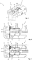
- FIG. 1 schematically shows a device 1 for positioning of connecting elements 2 in a transfer area for a in Fig. 1 Not shown joining or setting device in a perspective view.
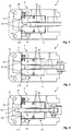
- Fig. 2 to 6 show the device 1 according to Fig. 1 in a sectional plan view before the assumption of a connecting element 2, in the acquisition of a connecting element 2 in a transfer area I, at the beginning of the transfer of the connecting element 2 from the transfer area I in the transfer area II, during the Transfer of the connecting element 2 from the transfer area I in the transfer area II, or after the transfer of the connecting element 2 in the transfer area II.
- the connecting element 2 is bolt-shaped with a head and a shaft.
- the device 1 comprises a feed device 3 and a locking device 4.
- the illustrated device 1 further comprises a bearing plate 10, with the aid of which the device 1 can be mounted on a system, not shown.
- the bearing plate 10 has a guide slope 100, so that one of a feed device 6 (see. Fig. 7 ) supplied connecting element 2 is guided in a direction to the transfer area II end of the transfer area I.
- a connecting element 2 can be transferred by means of the feed device 3 from the transfer area I into the transfer area II.
- the illustrated feed device 3 comprises an adjustable slide 30, which on a shaft of the connecting element 2 for displacing the connecting element 2 as in the FIGS. 4 to 6 shown attacks.
- the slider 30 has on the side surfaces in each case a longitudinally extending groove 32.
- the slide 30 is in one embodiment by means of a pneumatic cylinder 34 (see. Fig. 7 ) adjustable.
- a pneumatic cylinder alternative drives, for example by means of hydraulic and / or electrically conceivable.
- the pneumatic cylinder is designed to be single-acting or double-acting.
- the locking device 4 By means of the locking device 4, a movement of a connecting element 2 from the transfer area I in the transfer area II can be blocked.
- the locking device 4 has for this purpose at least one lever 40, wherein a movement of the connecting element from the transfer area I is locked in the transfer area II by means of the lever 40 arranged in a blocking position, and wherein the lever 40 for moving the connecting element in the transfer area in a release position is transferred.
- the locking device 4 comprises in the illustrated embodiment, two oppositely pivotable two-sided lever 40.
- the levers 40 each have a first arm 41 and a second arm 42 and are one between the first and the second arm lying axis by means of pin 43 between a locking position and a release position pivotable.
- the levers 40 At the first arms 41, the levers 40 each have a projection 44, the function of which will be described below.
- the levers 40 At the levers 40 each engage a spring element 45, which forces the lever 40 in the locked position, wherein in the FIGS. 2 to 6 only one spring element 45 is shown.
- the spring element 45 is inserted into corresponding recesses 46, 102 on the lever 40 or the bearing plate 100.
- the illustrated levers 40 have a dual function, since in addition a head facing the connecting element 2 also serves as a guide surface for the connecting elements 2 during the movement from the transfer area I into the transfer area II by means of the slide 30.
- the shank of the connecting elements 2 is arranged between the levers 40.
- the connecting element 2 is displaced along a guide rail arranged separately from the levers 40.
- a distance to the second arms 42 of the lever 40 at least partially smaller than a diameter of the shaft of the connecting elements 2.
- the second arms 42 each have on their the shank of the connecting element 2 facing surfaces on an inlet slope.
- the levers 40 are made of in the Fig. 1 to 3 Lock position shown in a in Fig. 5 shown release position pivotally, in which a distance between the second arms 42 is greater than a shaft diameter and a movement of the connecting element 2 in the direction of the transfer area II is possible.
- the levers 40 each have a projection 44 which projects into the travel of the slider 30 and cooperates with a side wall of the slider 30 for securing the lever 40 in the locked position.
- the slider 30 is driven in such a way that the slide 30 is moved towards the connecting element 2.
- the slider 30 is displaced relative to the levers 40.
- the grooves 32 allow a pivoting movement of the lever 40 from the locking position to the release position, wherein the projections 44 are inserted into the grooves 32 ,
- the spring elements 45 first force the lever 40 in the locked position, so that movement of the lever 40 is no longer locked, but the lever 40 initially remain in the locked position and continue the movement of the connecting elements 2 from the transfer area I in the transfer area II lock.
- the connecting element 2 is displaced in the direction of the transfer area II, wherein the levers 40 are forced against the force of the spring elements 45 into the release position, as in FIG Fig. 5 recognizable.
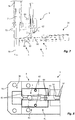
- Fig. 7 shows the device for setting connecting elements 2 with a feeding device 6 for the isolated feeding of connecting elements 2 to a transfer area I (see. Fig. 2 to 6 ), with a setting stamp 7 for setting a in a transfer area II (see. Fig. 2 to 6 ) positioned connector 2 and a device 1 according to the Fig. 1 to 6 comprising a feed device 3 and a locking device 4, wherein by means of the device 1, a connecting element 2 from the transfer area I in the transfer area II can be transferred.
- a housing 60 for connecting the feeder 6 and a housing 72 for the setting punch 7 are attached on the bearing plate 10.
- the housing 60 for connecting the feed device 6 has a channel piece 62, which opens approximately tangentially in the transfer region of the device 1 for positioning the connecting elements 2.
- the connecting elements 2 are conveyed through the channel piece 62 by means of compressed air.
- the connecting elements 2 are positioned in the illustrated embodiment in the transfer area such that the shaft extends substantially vertically and the head is disposed above the shaft.
- the setting punch 7 is displaceable in the illustrated embodiment in the vertical direction against the force of a return spring 74 by means of a drive, not shown.
- the guide element 70 is provided, by means of which the setting punch 7 is guided in the movement.
- the setting punch 7 can be moved along the guide element 70 in the direction of a component or an assembly. In other embodiments, no guide element is provided, wherein the setting punch 7 is guided by its housing 72.
- the feed device 3 comprises a slide 30, wherein the slide 30 is mechanically coupled to a pneumatic cylinder 34 which forms a drive.
- the slider 30 is driven such that its free end in the direction of the transfer area II (see. Fig. 2 to 6 ) is moved. If a connecting element 2 in the transfer area I (see. Fig. 2 to 6 ), this is transferred into the transfer area II as described above.
- the feed device 3 is preferably designed such that a maximum adjusting movement of the slide in the direction of the transfer area II in a no-lift, ie without entrainment of a connecting element 2, is greater than in a positioning stroke of a connecting element 2. In one embodiment is provided for this purpose, that the connecting element 2 is moved in a positioning stroke in an end position to an end stop, whereby the further movement of the slider 30 is locked.
- a sensor device By means of a sensor device can be detected whether the end position has been run over during the movement of the slider 30. If the sensor device detects an overrunning of the end position, an idle stroke is detected and the device 1 is driven to reset a connecting element and / or an error message is issued.
- the slide 30 can be withdrawn and the setting punch 7 driven for setting the connecting element 2.
- the Setzstempel 7 in an embodiment at the front end terminals that hold the connecting element 2 to the Setzstkov 7.
- the lever 40 of the locking device 4 are arranged parallel to the shaft of the connecting elements 2 and the connecting element 2 is displaced along a plane perpendicular to the shaft level.
- Fig. 8 shows a device 1 similar to the FIGS. 1 to 6 in a sectional plan view in the acquisition of a connecting element 2 in a transfer area I.
- the device 1 according to Fig. 8 corresponds essentially to the device 1 according to the FIGS. 1 to 6 and for the same components, the same reference numerals are used. A further detailed description of components already described will be omitted.
- the grooves 32 on inlet slopes 36 which guide the projections 44 from the guide grooves 32 in a retraction of the slider 30 from a in Fig. 6 position shown in the in Fig. 8 allow shown position.
- spring elements 45 can also be dispensed with. In a modification, however, spring elements or other force elements are provided, which force the lever 40 in the locked position.
Landscapes
- Engineering & Computer Science (AREA)
- Mechanical Engineering (AREA)
- Automatic Assembly (AREA)
- Labeling Devices (AREA)
- Moulds For Moulding Plastics Or The Like (AREA)
- Insertion Pins And Rivets (AREA)
Claims (10)
- Dispositif de positionnement d'éléments de fixation (2), avec- un dispositif d'avance (3) et- un dispositif de blocage (4), qui présente au moins un levier (40) pouvant pivoter entre une position de blocage et une position de libération,dans lequel un élément de fixation (2) peut être transféré au moyen du dispositif d'avance (3) d'une région de réception (I) à une région de cession (II) pour un dispositif de jonction, dans lequel ledit au moins un levier (40) peut pivoter entre une position de blocage et une position de libération, et dans lequel ledit au moins un levier (40) dans la position de blocage bloque un mouvement de l'élément de fixation (2) de la région de réception (I) à la région de cession (II), caractérisé en ce qu'il est prévu au moins une butée d'extrémité réglable par rapport audit au moins un levier (40), dans lequel un mouvement dudit au moins un levier (40) de la position de blocage à la position de libération peut être bloqué au moyen de ladite au moins une butée d'extrémité, dans lequel ledit au moins un levier (40) est formé par un levier bilatéral (40) avec un premier bras (41) et un second bras (42), et dans lequel un premier bras (41) dudit au moins un levier (40) coopère avec ladite au moins une butée d'extrémité pour le blocage d'un mouvement dudit au moins un levier (40) de la position de blocage à la position de libération et un second bras (42) dudit au moins un levier (40) fait office, dans la position de blocage, de mâchoire de retenue pour l'élément de fixation (2).
- Dispositif selon la revendication 1, caractérisé en ce que le dispositif de blocage présente deux leviers bilatéraux (40) pouvant pivoter en sens contraire, dans lequel les premiers bras (41) des leviers (40) coopèrent avec la butée d'extrémité pour le blocage d'un mouvement des leviers (40) de la position de blocage à la position de libération et les seconds bras (42) des leviers (40) font office de mâchoires de retenue pour l'élément de fixation (2).
- Dispositif selon une revendication 1 ou 2, caractérisé en ce qu'un élément de force, en particulier un élément de ressort (45), qui pousse le levier (40) dans la position de blocage, est associé audit au moins un levier (40).
- Dispositif selon une revendication 1, 2 ou 3, caractérisé en ce que l'élément de fixation (2) peut être déplacé dans la région de cession (II) le long du second bras (42) dudit au moins un levier (40) au moyen du dispositif d'avance.
- Dispositif selon l'une quelconque des revendications 1 à 4, caractérisé en ce que le dispositif d'avance (3) comprend un coulisseau (30) déplaçable linéairement par rapport audit au moins un levier (40), dans lequel une première partie du coulisseau (30) fait office de butée d'extrémité.
- Dispositif selon la revendication 5, caractérisé en ce que le coulisseau (30) présente une seconde partie, espacée de la première partie en direction longitudinale, dans lequel la seconde partie présente une forme, destinée à libérer un pivotement dudit au moins un levier (40) dans la position de libération après le franchissement d'une position de déverrouillage.
- Dispositif selon la revendication 6, caractérisé en ce que le premier bras (41) du levier (40) ou des leviers (40) présente une protubérance (44) pénétrant dans le chemin de réglage du coulisseau (30) et coopérant avec la butée d'extrémité, dans lequel de préférence une paroi du coulisseau (30) tournée vers la protubérance (44) présente une rainure (32) dans la seconde partie.
- Dispositif selon l'une quelconque des revendications 1 à 7, caractérisé en ce qu'un déplacement de réglage maximal du dispositif d'avance (3) en direction de la région de cession (II) lors d'une course à vide est plus grand que lors d'une course de positionnement d'un élément de fixation (2).
- Dispositif de pose d'éléments de fixation avec un dispositif d'alimentation (6) pour l'alimentation individualisée d'éléments de fixation à une région de réception (I), avec un poinçon de placement (7) pour placer un élément de fixation (2) positionné dans une région de cession (II) et avec un dispositif selon l'une quelconque des revendications 1 à 8, comprenant un dispositif d'avance (3) et un dispositif de blocage (4), au moyen duquel un élément de fixation (2) peut être transféré d'une région de réception (I) à une région de cession (II).
- Procédé de positionnement d'éléments de fixation (2), dans lequel on transfère un élément de fixation (2) au moyen d'un dispositif d'avance d'une région de réception (I) à une région de cession (II) pour un dispositif de jonction, dans lequel on bloque un mouvement de l'élément de fixation (2) de la région de réception (I) à la région de cession (II) au moyen d'au moins un levier (40) d'un dispositif de blocage (4) disposé dans une position de blocage, et dans lequel on transfère ledit au moins un levier (40) du dispositif de blocage (4) dans une position de libération pour le mouvement de l'élément de fixation (2) dans la région de cession (II), caractérisé en ce que lors d'une réception de l'élément de fixation (2) dans la région de réception (I), on bloque un mouvement dudit au moins un levier (40) de la position de blocage à la position de libération au moyen d'une butée d'extrémité, dans lequel ledit au moins un levier (40) est formé par un levier bilatéral (40) avec un premier bras (41) et un second bras (42), dans lequel un premier bras (41) dudit au moins un levier (40) coopère avec la butée d'extrémité lors d'une réception de l'élément de fixation (2) dans la région de réception (I), de telle manière qu'un mouvement du levier (40) de la position de blocage à la position de libération soit bloqué, et dans lequel on bloque le mouvement de l'élément de fixation (2) de la région de réception (I) à la région de cession (II) au moyen d'un second bras (42) dudit au moins un levier bilatéral (40) du dispositif de blocage (4) disposé dans la position de blocage.
Applications Claiming Priority (2)
| Application Number | Priority Date | Filing Date | Title |
|---|---|---|---|
| DE102015210322.6A DE102015210322A1 (de) | 2015-06-03 | 2015-06-03 | Vorrichtung und Verfahren zum Positionieren von Verbindungselementen |
| PCT/EP2016/061985 WO2016193140A1 (fr) | 2015-06-03 | 2016-05-27 | Dispositif et procédé de positionnement d'éléments de fixation |
Publications (2)
| Publication Number | Publication Date |
|---|---|
| EP3302875A1 EP3302875A1 (fr) | 2018-04-11 |
| EP3302875B1 true EP3302875B1 (fr) | 2019-05-22 |
Family
ID=56108621
Family Applications (1)
| Application Number | Title | Priority Date | Filing Date |
|---|---|---|---|
| EP16727389.5A Active EP3302875B1 (fr) | 2015-06-03 | 2016-05-27 | Dispositif et procédé de positionnement d'éléments de fixation |
Country Status (7)
| Country | Link |
|---|---|
| US (1) | US20180154488A1 (fr) |
| EP (1) | EP3302875B1 (fr) |
| JP (1) | JP6760972B2 (fr) |
| KR (1) | KR102613541B1 (fr) |
| CN (1) | CN108025408A (fr) |
| DE (1) | DE102015210322A1 (fr) |
| WO (1) | WO2016193140A1 (fr) |
Families Citing this family (6)
| Publication number | Priority date | Publication date | Assignee | Title |
|---|---|---|---|---|
| CN106670759B (zh) * | 2016-12-01 | 2019-01-11 | 江苏通正机械科技有限公司 | 割刀压板上料机构的上料装置 |
| GB2569126A (en) | 2017-12-05 | 2019-06-12 | Atlas Copco Ias Uk Ltd | Fastener magazines, and related supply systems and methods |
| GB2569122A (en) | 2017-12-05 | 2019-06-12 | Atlas Copco Ias Uk Ltd | Fastener handling devices for fastener setting machines, and related methods |
| GB2569127A (en) | 2017-12-05 | 2019-06-12 | Atlas Copco Ias Uk Ltd | Nose arrangements for fastener setting machines, and related methods |
| CN109127994B (zh) * | 2018-11-23 | 2024-04-02 | 东莞市诚大机械科技有限公司 | 一种铆钉送料装置及送料方法 |
| CN110252933A (zh) * | 2019-06-29 | 2019-09-20 | 山东红旗机电集团股份有限公司 | 飞行器尾杆与铆钉合装装置 |
Family Cites Families (16)
| Publication number | Priority date | Publication date | Assignee | Title |
|---|---|---|---|---|
| US3969808A (en) * | 1975-05-05 | 1976-07-20 | Multifastener Corporation | Fastener installation head |
| DE2603439A1 (de) * | 1975-05-05 | 1976-12-02 | Multifastener Corp | Stanzkopf zum befestigen von muttern |
| JPS5721895A (en) * | 1980-07-15 | 1982-02-04 | Nichiden Kikai Kk | Part inserting device |
| CA2318499C (fr) * | 1998-01-07 | 2007-03-27 | Fabristeel Products, Inc. | Tete d'installation d'elements de fixation pourvu d'un ensemble d'entrainement des elements de fixation pivotant |
| DE102004025492A1 (de) | 2004-05-21 | 2009-08-06 | Volkswagen Ag | Verfahren zum Fügen mittels mechanischen Eintreibens und Verschweißens eines Fügeelementes, sowie derartiges Fügeelement |
| DE102004042969A1 (de) * | 2004-09-02 | 2006-03-09 | Heiko Schmidt | System zum Verbinden von Schweißbolzen mit Werkstücken sowie Vorrichtung zum Positionieren und Vereinzeln von Schweißbolzen für ein derartiges System |
| DE102006016255A1 (de) | 2006-03-31 | 2007-10-04 | Arnold & Shinjo Gmbh & Co. Kg | Einpressen von Bolzen |
| CN100569435C (zh) * | 2008-03-27 | 2009-12-16 | 中国华录·松下电子信息有限公司 | 用于重力式机壳打螺钉机的螺刀头装置 |
| DE102009024433A1 (de) * | 2009-06-05 | 2010-12-09 | Newfrey Llc, Newark | Vereinzelungsschieber für eine Vorrichtung zum Zuführen eines Verbindungselements |
| CN202607211U (zh) * | 2011-05-17 | 2012-12-19 | 深圳市卓胜通科技有限公司 | 一种使用弹簧复位的夹嘴螺丝定位机构 |
| US8769788B2 (en) * | 2011-06-17 | 2014-07-08 | Btm Corporation | Rivet machine |
| CN104661791B (zh) | 2012-09-28 | 2018-04-13 | 富士机械制造株式会社 | 作业装置 |
| CN103862273A (zh) * | 2012-12-18 | 2014-06-18 | 富泰华工业(深圳)有限公司 | 螺钉定位装置 |
| CN104647014A (zh) * | 2013-11-21 | 2015-05-27 | 天津北科精工自动化科技发展有限责任公司 | 螺钉输送夹头 |
| CN204277419U (zh) * | 2014-10-30 | 2015-04-22 | 东莞市米勒机器人有限公司 | 一种防止螺丝翻转的夹头及其自动锁螺丝机 |
| US11000926B2 (en) * | 2017-12-20 | 2021-05-11 | Penn Automotive, Inc. | Fastener feed head |
-
2015
- 2015-06-03 DE DE102015210322.6A patent/DE102015210322A1/de not_active Withdrawn
-
2016
- 2016-05-27 KR KR1020187000218A patent/KR102613541B1/ko active IP Right Grant
- 2016-05-27 CN CN201680032050.5A patent/CN108025408A/zh active Pending
- 2016-05-27 WO PCT/EP2016/061985 patent/WO2016193140A1/fr active Application Filing
- 2016-05-27 JP JP2017562739A patent/JP6760972B2/ja active Active
- 2016-05-27 US US15/578,425 patent/US20180154488A1/en not_active Abandoned
- 2016-05-27 EP EP16727389.5A patent/EP3302875B1/fr active Active
Non-Patent Citations (1)
| Title |
|---|
| None * |
Also Published As
| Publication number | Publication date |
|---|---|
| JP2018519172A (ja) | 2018-07-19 |
| EP3302875A1 (fr) | 2018-04-11 |
| US20180154488A1 (en) | 2018-06-07 |
| DE102015210322A1 (de) | 2016-12-08 |
| JP6760972B2 (ja) | 2020-09-23 |
| WO2016193140A1 (fr) | 2016-12-08 |
| KR102613541B1 (ko) | 2023-12-13 |
| KR20180038438A (ko) | 2018-04-16 |
| CN108025408A (zh) | 2018-05-11 |
Similar Documents
| Publication | Publication Date | Title |
|---|---|---|
| EP3302875B1 (fr) | Dispositif et procédé de positionnement d'éléments de fixation | |
| DE4211276C2 (de) | Haltevorrichtung zum Halten, Führen und Freigeben eines Fügeteils, wie z.B. einer Mutter | |
| DE3448219C2 (fr) | ||
| DE112013004684B4 (de) | Schlauchkupplung | |
| EP2632629B1 (fr) | Dispositif de positionnement et d'amenée d'éléments de fixation | |
| AT515526B1 (de) | Biegewerkzeug und Greifvorrichtung zum Manipulieren des Biegewerkzeuges | |
| DE2314243A1 (de) | Einrichtung zum vorschuu und zur rueckholung einer auswerferplatte an formwerkzeugen fuer spritzgussmaschinen | |
| WO2015018526A1 (fr) | Ferrure servant à fixer un objet à un rail | |
| EP0755749B2 (fr) | Dispositif de guidage et/ou de fixation pour éléments, particulièrement pour éléments de fixation | |
| EP0486877A1 (fr) | Machine outil et méthode pour ouvrir et fermer une griffe | |
| EP0350516B1 (fr) | Dispositif de changement rapide de mandrins | |
| DE3632045C1 (de) | Vorrichtung zur Verbindung zweier Werkzeugteile | |
| EP2140968A2 (fr) | Dispositif et procédé destinés à la compression d'éléments de fixation | |
| DE10050619A1 (de) | Werkzeugbefestigungsvorrichtung | |
| EP2503920B1 (fr) | Système de guidage doté d'un dispositif mixte de ralentissement et d'accélération | |
| DE1627730B2 (de) | Vorrichtung zum Aufbringen von Befestigungselementen auf Schrauben bolzen | |
| DE102015122385B4 (de) | Werkzeug-kupplungssystem | |
| EP1839803A1 (fr) | Insertion de boulons | |
| EP2631031A2 (fr) | Dispositif de transfert pour le transfert en propulsion d'éléments de compression sur un outil de traitement de tôle et outil de traitement de tôle doté d'un tel dispositif de transfert | |
| EP3121141A1 (fr) | Rail de guidage pour un ascenseur | |
| EP3743240B1 (fr) | Dispositif pour freiner et tenir un élément de traitement | |
| DE102010048776A1 (de) | Schraubenhalterung | |
| DE102012009781A1 (de) | Schraubvorrichtung | |
| CH537803A (de) | Einrichtung zum Vorschub und zur Rückholung einer Auswerferplatte an Formwerkzeugen für Spritzgussmaschinen | |
| DE102021134528B3 (de) | Stanzwerkzeug für den mobilen Einsatz |
Legal Events
| Date | Code | Title | Description |
|---|---|---|---|
| STAA | Information on the status of an ep patent application or granted ep patent |
Free format text: STATUS: THE INTERNATIONAL PUBLICATION HAS BEEN MADE |
|
| PUAI | Public reference made under article 153(3) epc to a published international application that has entered the european phase |
Free format text: ORIGINAL CODE: 0009012 |
|
| STAA | Information on the status of an ep patent application or granted ep patent |
Free format text: STATUS: REQUEST FOR EXAMINATION WAS MADE |
|
| 17P | Request for examination filed |
Effective date: 20171214 |
|
| AK | Designated contracting states |
Kind code of ref document: A1 Designated state(s): AL AT BE BG CH CY CZ DE DK EE ES FI FR GB GR HR HU IE IS IT LI LT LU LV MC MK MT NL NO PL PT RO RS SE SI SK SM TR |
|
| AX | Request for extension of the european patent |
Extension state: BA ME |
|
| RIN1 | Information on inventor provided before grant (corrected) |
Inventor name: WOLFARTH, UWE Inventor name: LINDT, ALEX Inventor name: LUTZ, JOACHIM |
|
| DAV | Request for validation of the european patent (deleted) | ||
| DAX | Request for extension of the european patent (deleted) | ||
| GRAP | Despatch of communication of intention to grant a patent |
Free format text: ORIGINAL CODE: EPIDOSNIGR1 |
|
| STAA | Information on the status of an ep patent application or granted ep patent |
Free format text: STATUS: GRANT OF PATENT IS INTENDED |
|
| INTG | Intention to grant announced |
Effective date: 20181203 |
|
| GRAS | Grant fee paid |
Free format text: ORIGINAL CODE: EPIDOSNIGR3 |
|
| GRAA | (expected) grant |
Free format text: ORIGINAL CODE: 0009210 |
|
| STAA | Information on the status of an ep patent application or granted ep patent |
Free format text: STATUS: THE PATENT HAS BEEN GRANTED |
|
| AK | Designated contracting states |
Kind code of ref document: B1 Designated state(s): AL AT BE BG CH CY CZ DE DK EE ES FI FR GB GR HR HU IE IS IT LI LT LU LV MC MK MT NL NO PL PT RO RS SE SI SK SM TR |
|
| REG | Reference to a national code |
Ref country code: GB Ref legal event code: FG4D Free format text: NOT ENGLISH |
|
| REG | Reference to a national code |
Ref country code: CH Ref legal event code: EP |
|
| REG | Reference to a national code |
Ref country code: IE Ref legal event code: FG4D Free format text: LANGUAGE OF EP DOCUMENT: GERMAN |
|
| REG | Reference to a national code |
Ref country code: DE Ref legal event code: R096 Ref document number: 502016004797 Country of ref document: DE |
|
| REG | Reference to a national code |
Ref country code: AT Ref legal event code: REF Ref document number: 1135519 Country of ref document: AT Kind code of ref document: T Effective date: 20190615 |
|
| REG | Reference to a national code |
Ref country code: NL Ref legal event code: MP Effective date: 20190522 |
|
| REG | Reference to a national code |
Ref country code: LT Ref legal event code: MG4D |
|
| PG25 | Lapsed in a contracting state [announced via postgrant information from national office to epo] |
Ref country code: FI Free format text: LAPSE BECAUSE OF FAILURE TO SUBMIT A TRANSLATION OF THE DESCRIPTION OR TO PAY THE FEE WITHIN THE PRESCRIBED TIME-LIMIT Effective date: 20190522 Ref country code: NO Free format text: LAPSE BECAUSE OF FAILURE TO SUBMIT A TRANSLATION OF THE DESCRIPTION OR TO PAY THE FEE WITHIN THE PRESCRIBED TIME-LIMIT Effective date: 20190822 Ref country code: HR Free format text: LAPSE BECAUSE OF FAILURE TO SUBMIT A TRANSLATION OF THE DESCRIPTION OR TO PAY THE FEE WITHIN THE PRESCRIBED TIME-LIMIT Effective date: 20190522 Ref country code: NL Free format text: LAPSE BECAUSE OF FAILURE TO SUBMIT A TRANSLATION OF THE DESCRIPTION OR TO PAY THE FEE WITHIN THE PRESCRIBED TIME-LIMIT Effective date: 20190522 Ref country code: LT Free format text: LAPSE BECAUSE OF FAILURE TO SUBMIT A TRANSLATION OF THE DESCRIPTION OR TO PAY THE FEE WITHIN THE PRESCRIBED TIME-LIMIT Effective date: 20190522 Ref country code: ES Free format text: LAPSE BECAUSE OF FAILURE TO SUBMIT A TRANSLATION OF THE DESCRIPTION OR TO PAY THE FEE WITHIN THE PRESCRIBED TIME-LIMIT Effective date: 20190522 Ref country code: PT Free format text: LAPSE BECAUSE OF FAILURE TO SUBMIT A TRANSLATION OF THE DESCRIPTION OR TO PAY THE FEE WITHIN THE PRESCRIBED TIME-LIMIT Effective date: 20190922 Ref country code: AL Free format text: LAPSE BECAUSE OF FAILURE TO SUBMIT A TRANSLATION OF THE DESCRIPTION OR TO PAY THE FEE WITHIN THE PRESCRIBED TIME-LIMIT Effective date: 20190522 Ref country code: SE Free format text: LAPSE BECAUSE OF FAILURE TO SUBMIT A TRANSLATION OF THE DESCRIPTION OR TO PAY THE FEE WITHIN THE PRESCRIBED TIME-LIMIT Effective date: 20190522 |
|
| PG25 | Lapsed in a contracting state [announced via postgrant information from national office to epo] |
Ref country code: GR Free format text: LAPSE BECAUSE OF FAILURE TO SUBMIT A TRANSLATION OF THE DESCRIPTION OR TO PAY THE FEE WITHIN THE PRESCRIBED TIME-LIMIT Effective date: 20190823 Ref country code: LV Free format text: LAPSE BECAUSE OF FAILURE TO SUBMIT A TRANSLATION OF THE DESCRIPTION OR TO PAY THE FEE WITHIN THE PRESCRIBED TIME-LIMIT Effective date: 20190522 Ref country code: RS Free format text: LAPSE BECAUSE OF FAILURE TO SUBMIT A TRANSLATION OF THE DESCRIPTION OR TO PAY THE FEE WITHIN THE PRESCRIBED TIME-LIMIT Effective date: 20190522 Ref country code: BG Free format text: LAPSE BECAUSE OF FAILURE TO SUBMIT A TRANSLATION OF THE DESCRIPTION OR TO PAY THE FEE WITHIN THE PRESCRIBED TIME-LIMIT Effective date: 20190822 |
|
| REG | Reference to a national code |
Ref country code: CH Ref legal event code: PL |
|
| PG25 | Lapsed in a contracting state [announced via postgrant information from national office to epo] |
Ref country code: SK Free format text: LAPSE BECAUSE OF FAILURE TO SUBMIT A TRANSLATION OF THE DESCRIPTION OR TO PAY THE FEE WITHIN THE PRESCRIBED TIME-LIMIT Effective date: 20190522 Ref country code: RO Free format text: LAPSE BECAUSE OF FAILURE TO SUBMIT A TRANSLATION OF THE DESCRIPTION OR TO PAY THE FEE WITHIN THE PRESCRIBED TIME-LIMIT Effective date: 20190522 Ref country code: CZ Free format text: LAPSE BECAUSE OF FAILURE TO SUBMIT A TRANSLATION OF THE DESCRIPTION OR TO PAY THE FEE WITHIN THE PRESCRIBED TIME-LIMIT Effective date: 20190522 Ref country code: CH Free format text: LAPSE BECAUSE OF NON-PAYMENT OF DUE FEES Effective date: 20190531 Ref country code: EE Free format text: LAPSE BECAUSE OF FAILURE TO SUBMIT A TRANSLATION OF THE DESCRIPTION OR TO PAY THE FEE WITHIN THE PRESCRIBED TIME-LIMIT Effective date: 20190522 Ref country code: DK Free format text: LAPSE BECAUSE OF FAILURE TO SUBMIT A TRANSLATION OF THE DESCRIPTION OR TO PAY THE FEE WITHIN THE PRESCRIBED TIME-LIMIT Effective date: 20190522 Ref country code: LI Free format text: LAPSE BECAUSE OF NON-PAYMENT OF DUE FEES Effective date: 20190531 |
|
| REG | Reference to a national code |
Ref country code: BE Ref legal event code: MM Effective date: 20190531 |
|
| REG | Reference to a national code |
Ref country code: DE Ref legal event code: R097 Ref document number: 502016004797 Country of ref document: DE |
|
| PG25 | Lapsed in a contracting state [announced via postgrant information from national office to epo] |
Ref country code: IT Free format text: LAPSE BECAUSE OF FAILURE TO SUBMIT A TRANSLATION OF THE DESCRIPTION OR TO PAY THE FEE WITHIN THE PRESCRIBED TIME-LIMIT Effective date: 20190522 Ref country code: SM Free format text: LAPSE BECAUSE OF FAILURE TO SUBMIT A TRANSLATION OF THE DESCRIPTION OR TO PAY THE FEE WITHIN THE PRESCRIBED TIME-LIMIT Effective date: 20190522 Ref country code: MC Free format text: LAPSE BECAUSE OF FAILURE TO SUBMIT A TRANSLATION OF THE DESCRIPTION OR TO PAY THE FEE WITHIN THE PRESCRIBED TIME-LIMIT Effective date: 20190522 Ref country code: LU Free format text: LAPSE BECAUSE OF NON-PAYMENT OF DUE FEES Effective date: 20190527 |
|
| PLBE | No opposition filed within time limit |
Free format text: ORIGINAL CODE: 0009261 |
|
| STAA | Information on the status of an ep patent application or granted ep patent |
Free format text: STATUS: NO OPPOSITION FILED WITHIN TIME LIMIT |
|
| PG25 | Lapsed in a contracting state [announced via postgrant information from national office to epo] |
Ref country code: TR Free format text: LAPSE BECAUSE OF FAILURE TO SUBMIT A TRANSLATION OF THE DESCRIPTION OR TO PAY THE FEE WITHIN THE PRESCRIBED TIME-LIMIT Effective date: 20190522 |
|
| 26N | No opposition filed |
Effective date: 20200225 |
|
| PG25 | Lapsed in a contracting state [announced via postgrant information from national office to epo] |
Ref country code: PL Free format text: LAPSE BECAUSE OF FAILURE TO SUBMIT A TRANSLATION OF THE DESCRIPTION OR TO PAY THE FEE WITHIN THE PRESCRIBED TIME-LIMIT Effective date: 20190522 Ref country code: IE Free format text: LAPSE BECAUSE OF NON-PAYMENT OF DUE FEES Effective date: 20190527 |
|
| PG25 | Lapsed in a contracting state [announced via postgrant information from national office to epo] |
Ref country code: BE Free format text: LAPSE BECAUSE OF NON-PAYMENT OF DUE FEES Effective date: 20190531 Ref country code: SI Free format text: LAPSE BECAUSE OF FAILURE TO SUBMIT A TRANSLATION OF THE DESCRIPTION OR TO PAY THE FEE WITHIN THE PRESCRIBED TIME-LIMIT Effective date: 20190522 |
|
| PG25 | Lapsed in a contracting state [announced via postgrant information from national office to epo] |
Ref country code: FR Free format text: LAPSE BECAUSE OF NON-PAYMENT OF DUE FEES Effective date: 20190722 |
|
| GBPC | Gb: european patent ceased through non-payment of renewal fee |
Effective date: 20200527 |
|
| PG25 | Lapsed in a contracting state [announced via postgrant information from national office to epo] |
Ref country code: GB Free format text: LAPSE BECAUSE OF NON-PAYMENT OF DUE FEES Effective date: 20200527 |
|
| PG25 | Lapsed in a contracting state [announced via postgrant information from national office to epo] |
Ref country code: CY Free format text: LAPSE BECAUSE OF FAILURE TO SUBMIT A TRANSLATION OF THE DESCRIPTION OR TO PAY THE FEE WITHIN THE PRESCRIBED TIME-LIMIT Effective date: 20190522 |
|
| PG25 | Lapsed in a contracting state [announced via postgrant information from national office to epo] |
Ref country code: IS Free format text: LAPSE BECAUSE OF FAILURE TO SUBMIT A TRANSLATION OF THE DESCRIPTION OR TO PAY THE FEE WITHIN THE PRESCRIBED TIME-LIMIT Effective date: 20190922 |
|
| PG25 | Lapsed in a contracting state [announced via postgrant information from national office to epo] |
Ref country code: MT Free format text: LAPSE BECAUSE OF FAILURE TO SUBMIT A TRANSLATION OF THE DESCRIPTION OR TO PAY THE FEE WITHIN THE PRESCRIBED TIME-LIMIT Effective date: 20190522 Ref country code: HU Free format text: LAPSE BECAUSE OF FAILURE TO SUBMIT A TRANSLATION OF THE DESCRIPTION OR TO PAY THE FEE WITHIN THE PRESCRIBED TIME-LIMIT; INVALID AB INITIO Effective date: 20160527 |
|
| PG25 | Lapsed in a contracting state [announced via postgrant information from national office to epo] |
Ref country code: MK Free format text: LAPSE BECAUSE OF FAILURE TO SUBMIT A TRANSLATION OF THE DESCRIPTION OR TO PAY THE FEE WITHIN THE PRESCRIBED TIME-LIMIT Effective date: 20190522 |
|
| REG | Reference to a national code |
Ref country code: AT Ref legal event code: MM01 Ref document number: 1135519 Country of ref document: AT Kind code of ref document: T Effective date: 20210527 |
|
| PG25 | Lapsed in a contracting state [announced via postgrant information from national office to epo] |
Ref country code: AT Free format text: LAPSE BECAUSE OF NON-PAYMENT OF DUE FEES Effective date: 20210527 |
|
| P01 | Opt-out of the competence of the unified patent court (upc) registered |
Effective date: 20231031 |
|
| PGFP | Annual fee paid to national office [announced via postgrant information from national office to epo] |
Ref country code: DE Payment date: 20240522 Year of fee payment: 9 |