EP3302875B1 - Device and method for positioning connection elements - Google Patents
Device and method for positioning connection elements Download PDFInfo
- Publication number
- EP3302875B1 EP3302875B1 EP16727389.5A EP16727389A EP3302875B1 EP 3302875 B1 EP3302875 B1 EP 3302875B1 EP 16727389 A EP16727389 A EP 16727389A EP 3302875 B1 EP3302875 B1 EP 3302875B1
- Authority
- EP
- European Patent Office
- Prior art keywords
- lever
- connecting element
- movement
- arm
- blocking
- Prior art date
- Legal status (The legal status is an assumption and is not a legal conclusion. Google has not performed a legal analysis and makes no representation as to the accuracy of the status listed.)
- Active
Links
- 238000000034 method Methods 0.000 title claims description 6
- 230000000903 blocking effect Effects 0.000 claims description 26
- 230000013011 mating Effects 0.000 description 2
- 238000003825 pressing Methods 0.000 description 2
- 230000004913 activation Effects 0.000 description 1
- 230000005540 biological transmission Effects 0.000 description 1
- 238000007664 blowing Methods 0.000 description 1
- 230000001419 dependent effect Effects 0.000 description 1
- 230000009977 dual effect Effects 0.000 description 1
- 230000004048 modification Effects 0.000 description 1
- 238000012986 modification Methods 0.000 description 1
- 230000002028 premature Effects 0.000 description 1
- 230000003319 supportive effect Effects 0.000 description 1
- 230000001960 triggered effect Effects 0.000 description 1
Images
Classifications
-
- B—PERFORMING OPERATIONS; TRANSPORTING
- B21—MECHANICAL METAL-WORKING WITHOUT ESSENTIALLY REMOVING MATERIAL; PUNCHING METAL
- B21J—FORGING; HAMMERING; PRESSING METAL; RIVETING; FORGE FURNACES
- B21J15/00—Riveting
- B21J15/10—Riveting machines
- B21J15/30—Particular elements, e.g. supports; Suspension equipment specially adapted for portable riveters
- B21J15/32—Devices for inserting or holding rivets in position with or without feeding arrangements
-
- B—PERFORMING OPERATIONS; TRANSPORTING
- B23—MACHINE TOOLS; METAL-WORKING NOT OTHERWISE PROVIDED FOR
- B23P—METAL-WORKING NOT OTHERWISE PROVIDED FOR; COMBINED OPERATIONS; UNIVERSAL MACHINE TOOLS
- B23P19/00—Machines for simply fitting together or separating metal parts or objects, or metal and non-metal parts, whether or not involving some deformation; Tools or devices therefor so far as not provided for in other classes
- B23P19/001—Article feeders for assembling machines
- B23P19/006—Holding or positioning the article in front of the applying tool
-
- B—PERFORMING OPERATIONS; TRANSPORTING
- B23—MACHINE TOOLS; METAL-WORKING NOT OTHERWISE PROVIDED FOR
- B23P—METAL-WORKING NOT OTHERWISE PROVIDED FOR; COMBINED OPERATIONS; UNIVERSAL MACHINE TOOLS
- B23P19/00—Machines for simply fitting together or separating metal parts or objects, or metal and non-metal parts, whether or not involving some deformation; Tools or devices therefor so far as not provided for in other classes
- B23P19/001—Article feeders for assembling machines
- B23P19/007—Picking-up and placing mechanisms
-
- B—PERFORMING OPERATIONS; TRANSPORTING
- B23—MACHINE TOOLS; METAL-WORKING NOT OTHERWISE PROVIDED FOR
- B23P—METAL-WORKING NOT OTHERWISE PROVIDED FOR; COMBINED OPERATIONS; UNIVERSAL MACHINE TOOLS
- B23P19/00—Machines for simply fitting together or separating metal parts or objects, or metal and non-metal parts, whether or not involving some deformation; Tools or devices therefor so far as not provided for in other classes
- B23P19/04—Machines for simply fitting together or separating metal parts or objects, or metal and non-metal parts, whether or not involving some deformation; Tools or devices therefor so far as not provided for in other classes for assembling or disassembling parts
- B23P19/06—Screw or nut setting or loosening machines
- B23P19/062—Pierce nut setting machines
Definitions
- the invention relates to a device and a method for positioning of connecting elements, wherein a connecting element by means of a feed device from a transfer area in a transfer area for a joining device can be transferred and wherein a locking device in the locked position blocks movement of the connecting element from the transfer area in the transfer area.
- the invention further relates to a device for setting connecting elements.
- the connecting element is, for example, a press-in bolt or an example DE 10 2004 025 492 A1 known joining element.
- These connecting elements have a head and a shaft, wherein the shaft has a thread in one embodiment, a cutting tip in other embodiments.
- a circumferential recess is formed below the head, which serves for axially fixed connection of the connecting element with a component or an assembly into which or the connecting element is pressed.
- a method and a device for pressing in Einpressbolzen is for example off DE 10 2006 016 255 A1 known.
- the invention is based on the object to provide a way to position fasteners with high accuracy at a specified time for a joining device, such as a setting die.
- an apparatus for positioning connecting elements with a feed device and a locking device which has at least one lever pivotable between a blocking position and a release position wherein a connecting element can be transferred by means of the feed device from a transfer region into a transfer region for a joining device, wherein the at least one lever between a locking position and a release position is pivotable, wherein the at least one lever in the locking position blocks movement of the connecting element from the transfer area into the transfer area, wherein at least one relative to the at least one lever adjustable end stop provided is, by means of which a movement of the at least one lever from the lock position to the release position is lockable, wherein the at least one lever is designed as a two-sided lever with a first arm and a second arm, and wherein a first arm of the at least one lever with the at least an end stop for blocking movement of the at least one lever from the locking position to the release position cooperates and a second arm of the at least one lever in the locking position acts as holding jaws for the connecting element
- the connecting element is conveyed for example by means of compressed air in the transfer area.
- the end stop prevents a running into the takeover area at high speed and / or high kinetic energy connecting element acts on the locking device such that it is transferred early and / or uncontrolled in the release position.
- the end stop thus prevents uncontrolled and / or premature movement of the connecting element from the transfer area into the transfer area.
- a transfer of the connecting element into the transfer region for a joining device, for example for a setting punch, by means of the feed device, said movement is made possible only after or with a movement of the end stop.
- the device preferably has a suitable mating surface with which the locking device and / or the end stop cooperate.
- the end stop is positioned in an embodiment with only one lever on an inner side of the first arm of the lever.
- the locking means comprises two oppositely pivotable two-sided levers, wherein the first arms of the lever cooperate with the end stop for blocking a movement of the lever from the locking position to the release position and the second arms of the levers act as holding jaws for the connecting element.
- the levers preferably are arranged symmetrically to a center line. To secure the locking device in the locking position, the end stop is pushed between the two first arms of the levers, so that a pivoting movement of the lever, through which the two first arms approach, is prevented.
- the connecting element is securely clamped between the two second arms of the lever.
- the at least one lever is assigned a force element, in particular a spring element, which forces the lever into the blocking position. Since the force element acts only supportive on the at least one lever, it is possible to dimension a spring force smaller than, for example, in one off DE 10 2006 016 255 A1 known device. In some embodiments, the force element is dispensed with.
- a guide device for example, a guide rail is provided, along which the connecting elements are moved from the transfer area into the transfer area.
- the connecting element is displaceable by means of the feed device along the second arm of the one lever or along the second arms of the two levers in the transfer area.
- the second arm of the lever or the second arms of the lever preferably have a guide surface for this purpose, wherein, for example, in a connecting element having a shaft and a head a bottom of the head rests on the guide surface and the shaft between the levers - or between a lever and a guide rail - guided in the release position of the lever and clamped in the locked position.
- the feed device preferably comprises a relative to the at least one lever linearly displaceable slider.
- the slider engages on the shaft for an adjusting movement of the connecting element.
- a shape of a free end of the slider is adapted in advantageous embodiments of the shape of the connecting element.
- the end stop is designed in a configuration separate from the slider, wherein a movement of the end stop and the slider are coordinated, so that a release of the locking device is ensured from the locking position during an adjustment movement of the connecting element by means of the slider.
- the end stop is moved, for example, in opposite directions to the slide from the area between the levers or between a lever and a counter surface.
- a first portion of the slider acts as an end stop. This can be dispensed with additional drive means, transmission elements or the like.
- the slider preferably has a second portion spaced longitudinally from the first portion, the second portion having a shape to release a pivoting of the lever to the release position after passing over an unlocking position.
- a cross section of a slider inserted between two levers is not constant.
- the slider is relative to the locking device adjustable. In a first position, acting as an end stop first portion between the first arms of the lever is inserted, so that a pivoting of the lever is locked in the release position.
- the second section is designed such that a pivoting movement of the lever in the release position is possible.
- a cross-section of the slider in the plane of the levers in the second portion is tapered with respect to the first portion.
- the first arm of the lever or the lever projecting into the travel of the slider cooperating with the end stop protrusion, wherein preferably a projection facing the wall of the slider in the second portion has a groove.
- a maximum adjusting movement of the feed device in the direction of the transfer region is greater in the case of an idle stroke than in the case of a positioning stroke of a connecting element.
- an actuating movement is limited by the connecting element, whereas in the case of an idle stroke, i. a movement without a connecting element has been inserted, the feed device, in particular the slide, is moved over this end position.
- the movement of the slide can be detected by means of sensors, this allows to easily query the presence of a connecting element in the transfer area, only if there is a connecting element, an activation of the joining device takes place, for example, a setting process is triggered.
- a device for setting connecting elements with a feed device for the occasional supply of connecting elements to a transfer area; with a setting punch for setting a connecting element positioned in a transfer area and with a device for positioning connecting elements, wherein the device for positioning connecting elements a feed device, by means of which a connecting element from the transfer area is transferable into a transfer area, a locking device with at least one between a locking position and a release position adjustable lever, and having a relative to the lever adjustable end stop, wherein the lever in the locking position blocks movement of the connecting element from the transfer area and wherein means of the end stop movement of the lever from the locked position in the Release position is lockable.
- the connecting element is for example pressed or inserted by means of the device into a component or an assembly.
- the setting punch has at its free end a device by means of which the connecting element is held on the setting punch.
- a magnet and / or a suction device which holds the connecting element by means of negative pressure, is provided.
- mechanical clamps are provided for holding the connecting elements on the setting punch.
- the delivery device is preferably designed as a blowing device comprising at least one channel piece, wherein the connecting element is blown through the channel piece with air pressure.
- the adjoining the device for positioning of connecting elements channel piece is preferably curved, wherein an end portion opens tangentially into the transfer area.
- a connecting element is transferred by means of a feed device from a transfer area in a transfer area for a joining device, a movement of the connecting element from the transfer area in the transfer area by means of at least one arranged in a blocking position lever of a locking device is locked, the at least one lever is moved to move the connecting element in the transfer area in a release position, provided that when a takeover of the connecting element in the transfer area, a movement of the at least one lever is locked from the locked position to the release position by means of an end stop, wherein the at least one lever is designed as a two-sided lever with a first arm and a second arm, wherein a first arm of the at least one lever with the end stop at a take de s connecting member in the transfer area cooperates, so that a movement of the lever from the lock position is locked in the release position, and wherein the movement of the connecting element from the transfer area in the transfer area by a second arm of at least one arranged in the
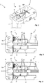
- FIG. 1 schematically shows a device 1 for positioning of connecting elements 2 in a transfer area for a in Fig. 1 Not shown joining or setting device in a perspective view.
- Fig. 2 to 6 show the device 1 according to Fig. 1 in a sectional plan view before the assumption of a connecting element 2, in the acquisition of a connecting element 2 in a transfer area I, at the beginning of the transfer of the connecting element 2 from the transfer area I in the transfer area II, during the Transfer of the connecting element 2 from the transfer area I in the transfer area II, or after the transfer of the connecting element 2 in the transfer area II.
- the connecting element 2 is bolt-shaped with a head and a shaft.
- the device 1 comprises a feed device 3 and a locking device 4.
- the illustrated device 1 further comprises a bearing plate 10, with the aid of which the device 1 can be mounted on a system, not shown.
- the bearing plate 10 has a guide slope 100, so that one of a feed device 6 (see. Fig. 7 ) supplied connecting element 2 is guided in a direction to the transfer area II end of the transfer area I.
- a connecting element 2 can be transferred by means of the feed device 3 from the transfer area I into the transfer area II.
- the illustrated feed device 3 comprises an adjustable slide 30, which on a shaft of the connecting element 2 for displacing the connecting element 2 as in the FIGS. 4 to 6 shown attacks.
- the slider 30 has on the side surfaces in each case a longitudinally extending groove 32.
- the slide 30 is in one embodiment by means of a pneumatic cylinder 34 (see. Fig. 7 ) adjustable.
- a pneumatic cylinder alternative drives, for example by means of hydraulic and / or electrically conceivable.
- the pneumatic cylinder is designed to be single-acting or double-acting.
- the locking device 4 By means of the locking device 4, a movement of a connecting element 2 from the transfer area I in the transfer area II can be blocked.
- the locking device 4 has for this purpose at least one lever 40, wherein a movement of the connecting element from the transfer area I is locked in the transfer area II by means of the lever 40 arranged in a blocking position, and wherein the lever 40 for moving the connecting element in the transfer area in a release position is transferred.
- the locking device 4 comprises in the illustrated embodiment, two oppositely pivotable two-sided lever 40.
- the levers 40 each have a first arm 41 and a second arm 42 and are one between the first and the second arm lying axis by means of pin 43 between a locking position and a release position pivotable.
- the levers 40 At the first arms 41, the levers 40 each have a projection 44, the function of which will be described below.
- the levers 40 At the levers 40 each engage a spring element 45, which forces the lever 40 in the locked position, wherein in the FIGS. 2 to 6 only one spring element 45 is shown.
- the spring element 45 is inserted into corresponding recesses 46, 102 on the lever 40 or the bearing plate 100.
- the illustrated levers 40 have a dual function, since in addition a head facing the connecting element 2 also serves as a guide surface for the connecting elements 2 during the movement from the transfer area I into the transfer area II by means of the slide 30.
- the shank of the connecting elements 2 is arranged between the levers 40.
- the connecting element 2 is displaced along a guide rail arranged separately from the levers 40.
- a distance to the second arms 42 of the lever 40 at least partially smaller than a diameter of the shaft of the connecting elements 2.
- the second arms 42 each have on their the shank of the connecting element 2 facing surfaces on an inlet slope.
- the levers 40 are made of in the Fig. 1 to 3 Lock position shown in a in Fig. 5 shown release position pivotally, in which a distance between the second arms 42 is greater than a shaft diameter and a movement of the connecting element 2 in the direction of the transfer area II is possible.
- the levers 40 each have a projection 44 which projects into the travel of the slider 30 and cooperates with a side wall of the slider 30 for securing the lever 40 in the locked position.
- the slider 30 is driven in such a way that the slide 30 is moved towards the connecting element 2.
- the slider 30 is displaced relative to the levers 40.
- the grooves 32 allow a pivoting movement of the lever 40 from the locking position to the release position, wherein the projections 44 are inserted into the grooves 32 ,
- the spring elements 45 first force the lever 40 in the locked position, so that movement of the lever 40 is no longer locked, but the lever 40 initially remain in the locked position and continue the movement of the connecting elements 2 from the transfer area I in the transfer area II lock.
- the connecting element 2 is displaced in the direction of the transfer area II, wherein the levers 40 are forced against the force of the spring elements 45 into the release position, as in FIG Fig. 5 recognizable.
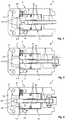
- Fig. 7 shows the device for setting connecting elements 2 with a feeding device 6 for the isolated feeding of connecting elements 2 to a transfer area I (see. Fig. 2 to 6 ), with a setting stamp 7 for setting a in a transfer area II (see. Fig. 2 to 6 ) positioned connector 2 and a device 1 according to the Fig. 1 to 6 comprising a feed device 3 and a locking device 4, wherein by means of the device 1, a connecting element 2 from the transfer area I in the transfer area II can be transferred.
- a housing 60 for connecting the feeder 6 and a housing 72 for the setting punch 7 are attached on the bearing plate 10.
- the housing 60 for connecting the feed device 6 has a channel piece 62, which opens approximately tangentially in the transfer region of the device 1 for positioning the connecting elements 2.
- the connecting elements 2 are conveyed through the channel piece 62 by means of compressed air.
- the connecting elements 2 are positioned in the illustrated embodiment in the transfer area such that the shaft extends substantially vertically and the head is disposed above the shaft.
- the setting punch 7 is displaceable in the illustrated embodiment in the vertical direction against the force of a return spring 74 by means of a drive, not shown.
- the guide element 70 is provided, by means of which the setting punch 7 is guided in the movement.
- the setting punch 7 can be moved along the guide element 70 in the direction of a component or an assembly. In other embodiments, no guide element is provided, wherein the setting punch 7 is guided by its housing 72.
- the feed device 3 comprises a slide 30, wherein the slide 30 is mechanically coupled to a pneumatic cylinder 34 which forms a drive.
- the slider 30 is driven such that its free end in the direction of the transfer area II (see. Fig. 2 to 6 ) is moved. If a connecting element 2 in the transfer area I (see. Fig. 2 to 6 ), this is transferred into the transfer area II as described above.
- the feed device 3 is preferably designed such that a maximum adjusting movement of the slide in the direction of the transfer area II in a no-lift, ie without entrainment of a connecting element 2, is greater than in a positioning stroke of a connecting element 2. In one embodiment is provided for this purpose, that the connecting element 2 is moved in a positioning stroke in an end position to an end stop, whereby the further movement of the slider 30 is locked.
- a sensor device By means of a sensor device can be detected whether the end position has been run over during the movement of the slider 30. If the sensor device detects an overrunning of the end position, an idle stroke is detected and the device 1 is driven to reset a connecting element and / or an error message is issued.
- the slide 30 can be withdrawn and the setting punch 7 driven for setting the connecting element 2.
- the Setzstempel 7 in an embodiment at the front end terminals that hold the connecting element 2 to the Setzstkov 7.
- the lever 40 of the locking device 4 are arranged parallel to the shaft of the connecting elements 2 and the connecting element 2 is displaced along a plane perpendicular to the shaft level.
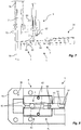
- Fig. 8 shows a device 1 similar to the FIGS. 1 to 6 in a sectional plan view in the acquisition of a connecting element 2 in a transfer area I.
- the device 1 according to Fig. 8 corresponds essentially to the device 1 according to the FIGS. 1 to 6 and for the same components, the same reference numerals are used. A further detailed description of components already described will be omitted.
- the grooves 32 on inlet slopes 36 which guide the projections 44 from the guide grooves 32 in a retraction of the slider 30 from a in Fig. 6 position shown in the in Fig. 8 allow shown position.
- spring elements 45 can also be dispensed with. In a modification, however, spring elements or other force elements are provided, which force the lever 40 in the locked position.
Description
Die Erfindung betrifft eine Vorrichtung und ein Verfahren zum Positionieren von Verbindungselementen, wobei ein Verbindungselement mittels einer Vorschubeinrichtung aus einem Übernahmebereich in einen Übergabebereich für eine Fügeeinrichtung überführbar ist und wobei eine Sperreinrichtung in der Sperrposition eine Bewegung des Verbindungselement aus dem Übernahmebereich in den Übergabebereich sperrt. Die Erfindung betrifft weiter eine Vorrichtung zum Setzen von Verbindungselementen.The invention relates to a device and a method for positioning of connecting elements, wherein a connecting element by means of a feed device from a transfer area in a transfer area for a joining device can be transferred and wherein a locking device in the locked position blocks movement of the connecting element from the transfer area in the transfer area. The invention further relates to a device for setting connecting elements.
Bei dem Verbindungselement handelt es sich beispielsweise um einen Einpressbolzen oder ein beispielsweise aus
Ein Verfahren und eine Vorrichtung zum Einpressen von Einpressbolzen ist beispielsweise aus
Der Erfindung liegt die Aufgabe zu Grunde eine Möglichkeit zu schaffen, Verbindungselemente mit einer hohen Genauigkeit zu einem festgelegten Zeitpunkt für eine Fügeeinrichtung, beispielsweise einen Setzstempel, zu positionieren.The invention is based on the object to provide a way to position fasteners with high accuracy at a specified time for a joining device, such as a setting die.
Diese Aufgabe wird durch die Gegenstände der unabhängigen Ansprüche gelöst. Vorteilhafte Ausführungsformen sind Gegenstand der abhängigen Ansprüche.This object is solved by the subject matters of the independent claims. Advantageous embodiments are the subject of the dependent claims.
Gemäß einem ersten Aspekt wird eine Vorrichtung zum Positionieren von Verbindungselementen mit einer Vorschubeinrichtung und einer Sperreinrichtung die mindestens einen zwischen einer Sperrposition und einer Freigabeposition verschwenkbaren Hebel aufweist, geschaffen, wobei ein Verbindungselement mittels der Vorschubeinrichtung aus einem Übernahmebereich in einen Übergabebereich für eine Fügeeinrichtung überführbar ist, wobei der mindestens eine Hebel zwischen einer Sperrposition und einer Freigabeposition verschwenkbar ist, wobei der mindestens eine Hebel in der Sperrposition eine Bewegung des Verbindungselements aus dem Übernahmebereich in den Übergabebereich sperrt, wobei mindestens ein relativ zu dem mindestens einen Hebel verstellbarer Endanschlag vorgesehen ist, mittels welchem eine Bewegung des mindestens einen Hebels aus der Sperrposition in die Freigabeposition sperrbar ist, wobei der mindestens eine Hebel als zweiseitiger Hebel mit einem ersten Arm und einem zweiten Arm gestaltet ist, und wobei ein erster Arm des mindestens einen Hebels mit dem mindestens einen Endanschlag zur Sperrung einer Bewegung des mindestens einen Hebels aus der Sperrposition in die Freigabeposition zusammenwirkt und ein zweiter Arm des mindestens einen Hebels in der Sperrposition als Haltebacken für das Verbindungselement fungiert .According to a first aspect, an apparatus for positioning connecting elements with a feed device and a locking device which has at least one lever pivotable between a blocking position and a release position is provided, wherein a connecting element can be transferred by means of the feed device from a transfer region into a transfer region for a joining device, wherein the at least one lever between a locking position and a release position is pivotable, wherein the at least one lever in the locking position blocks movement of the connecting element from the transfer area into the transfer area, wherein at least one relative to the at least one lever adjustable end stop provided is, by means of which a movement of the at least one lever from the lock position to the release position is lockable, wherein the at least one lever is designed as a two-sided lever with a first arm and a second arm, and wherein a first arm of the at least one lever with the at least an end stop for blocking movement of the at least one lever from the locking position to the release position cooperates and a second arm of the at least one lever in the locking position acts as holding jaws for the connecting element.
Das Verbindungselement wird beispielsweise mittels Druckluft in den Übernahmebereich gefördert. Der Endanschlag verhindert, dass ein in den Übernahmebereich mit hoher Geschwindigkeit und/oder hoher kinetischer Energie einlaufendes Verbindungselement derart auf die Sperreinrichtung wirkt, dass diese frühzeitig und/oder unkontrolliert in die Freigabeposition überführt wird. Der Endanschlag verhindert somit eine unkontrollierte und/oder frühzeitige Bewegung des Verbindungselements aus dem Übernahmebereich in den Übergabebereich. Eine Überführung des Verbindungselements in den Übergabebereich für eine Fügeeinrichtung, beispielsweise für einen Setzstempel, erfolgt mittels der Vorschubeinrichtung, wobei diese Bewegung erst nach oder mit einem Bewegen des Endanschlags ermöglicht wird.The connecting element is conveyed for example by means of compressed air in the transfer area. The end stop prevents a running into the takeover area at high speed and / or high kinetic energy connecting element acts on the locking device such that it is transferred early and / or uncontrolled in the release position. The end stop thus prevents uncontrolled and / or premature movement of the connecting element from the transfer area into the transfer area. A transfer of the connecting element into the transfer region for a joining device, for example for a setting punch, by means of the feed device, said movement is made possible only after or with a movement of the end stop.
Sofern nur ein Hebel vorgesehen ist, weist die Vorrichtung vorzugsweise eine geeignete Gegenfläche auf, mit welcher die Sperreinrichtung und/oder der Endanschlag zusammenwirken. Für eine Sicherung der Sperreinrichtung in der Sperrposition wird der Endanschlag in einer Ausgestaltung mit nur einem Hebel an einer Innenseite des ersten Arms des Hebels positioniert. Dadurch wird eine Schwenkbewegung des Hebels, bei welcher ein zweiter Arm nach außen verschwenkt wird, verhindert und das Verbindungselement ist zwischen dem zweiten Arm des Hebels und einer Gegenfläche klemmbar.If only one lever is provided, the device preferably has a suitable mating surface with which the locking device and / or the end stop cooperate. For securing the locking device in the locking position, the end stop is positioned in an embodiment with only one lever on an inner side of the first arm of the lever. Thereby, a pivoting movement of the lever, in which a second arm is pivoted outwardly prevented, and the connecting element is clamped between the second arm of the lever and a mating surface.
In einer Ausgestaltung umfasst die Sperreinrichtung zwei gegenläufig verschwenkbare zweiseitige Hebel, wobei die ersten Arme der Hebel mit dem Endanschlag zur Sperrung einer Bewegung der Hebel aus der Sperrposition in die Freigabeposition zusammenwirken und die zweiten Arme der Hebel als Haltebacken für das Verbindungselement fungieren.. Die Hebel vorzugsweise sind symmetrisch zu einer Mittellinie angeordnet. Für eine Sicherung der Sperreinrichtung in der Sperrposition wird der Endanschlag zwischen die zwei ersten Arme der Hebel geschoben, sodass eine Schwenkbewegung der Hebel, durch welche sich die zwei ersten Arme annähern, verhindert wird. Das Verbindungselement ist so sicher zwischen den beiden zweiten Armen der Hebel klemmbar.In one embodiment, the locking means comprises two oppositely pivotable two-sided levers, wherein the first arms of the lever cooperate with the end stop for blocking a movement of the lever from the locking position to the release position and the second arms of the levers act as holding jaws for the connecting element. The levers preferably are arranged symmetrically to a center line. To secure the locking device in the locking position, the end stop is pushed between the two first arms of the levers, so that a pivoting movement of the lever, through which the two first arms approach, is prevented. The connecting element is securely clamped between the two second arms of the lever.
In einer Ausgestaltung ist dem mindestens einen Hebel ein Kraftelement, insbesondere ein Federelement zugeordnet, welches den Hebel in die Sperrposition zwingt. Da das Kraftelement nur unterstützend auf den mindestens einen Hebel wirkt, ist es möglich, eine Federkraft kleiner zu dimensionieren, als beispielsweise bei einer aus
In einer Ausgestaltung ist eine Führungseinrichtung, beispielsweise eine Führungsschiene vorgesehen, entlang welcher die Verbindungselemente aus dem Übernahmebereich in den Übergabebereich verschoben werden. In vorteilhaften Ausgestaltungen ist das Verbindungselement mittels der Vorschubeinrichtung entlang des zweiten Arms des einen Hebels oder entlang der zweiten Arme der zwei Hebel in den Übergabebereich verschieblich. Der zweite Arm des Hebels oder die zweiten Arme der Hebel weisen zu diesem Zweck vorzugsweise eine Führungsfläche auf, wobei beispielsweise bei einem einen Schaft und einen Kopf aufweisenden Verbindungselement eine Unterseite des Kopfes auf der Führungsfläche aufliegt und der Schaft zwischen den Hebeln - oder zwischen einem Hebel und einer Führungsschiene - in der Freigabeposition der Hebel geführt und in der Sperrposition geklemmt ist.In one embodiment, a guide device, for example, a guide rail is provided, along which the connecting elements are moved from the transfer area into the transfer area. In advantageous embodiments, the connecting element is displaceable by means of the feed device along the second arm of the one lever or along the second arms of the two levers in the transfer area. The second arm of the lever or the second arms of the lever preferably have a guide surface for this purpose, wherein, for example, in a connecting element having a shaft and a head a bottom of the head rests on the guide surface and the shaft between the levers - or between a lever and a guide rail - guided in the release position of the lever and clamped in the locked position.
Die Vorschubeinrichtung umfasst vorzugsweise einen relativ zu dem mindestens einen Hebel linear verschiebbaren Schieber. Der Schieber greift beispielsweise bei einem einen Schaft und einen Kopf aufweisenden Verbindungselement an dem Schaft für eine Verstellbewegung des Verbindungselements an. Eine Form eines freien Endes des Schiebers ist dabei in vorteilhaften Ausgestaltungen an die Form des Verbindungselements angepasst. Der Endanschlag ist in einer Ausgestaltung getrennt von dem Schieber gestaltet, wobei eine Bewegung des Endanschlags und des Schiebers aufeinander abgestimmt sind, sodass eine Freigabe der Sperreinrichtung aus der Sperrposition bei einer Verstellbewegung des Verbindungselements mittels des Schiebers sichergestellt ist. Der Endanschlag wird dabei beispielsweise gegenläufig zu dem Schieber aus dem Bereich zwischen den Hebeln oder zwischen einem Hebel und einer Gegenfläche bewegt. In vorteilhaften Ausgestaltungen fungiert ein erster Abschnitt des Schiebers als Endanschlag. Dadurch kann auf zusätzliche Antriebsmittel, Getriebeelemente oder dergleichen verzichtet werden.The feed device preferably comprises a relative to the at least one lever linearly displaceable slider. For example, in the case of a connecting element having a shaft and a head, the slider engages on the shaft for an adjusting movement of the connecting element. A shape of a free end of the slider is adapted in advantageous embodiments of the shape of the connecting element. The end stop is designed in a configuration separate from the slider, wherein a movement of the end stop and the slider are coordinated, so that a release of the locking device is ensured from the locking position during an adjustment movement of the connecting element by means of the slider. The end stop is moved, for example, in opposite directions to the slide from the area between the levers or between a lever and a counter surface. In advantageous embodiments, a first portion of the slider acts as an end stop. This can be dispensed with additional drive means, transmission elements or the like.
Der Schieber weist vorzugsweise einen in Längsrichtung zu dem ersten Abschnitt beabstandeten, zweiten Abschnitt auf, wobei der zweite Abschnitt eine Gestalt aufweist, um nach Überfahren einer Entriegelposition ein Verschwenken des Hebels in die Freigabeposition freizugeben. In anderen Worten ist beispielsweise ein Querschnitt eines zwischen zwei Hebel eingeführten Schiebers nicht konstant. Der Schieber ist relativ zu der Sperreinrichtung verstellbar. In einer ersten Position ist ein als Endanschlag fungierender erster Abschnitt zwischen den ersten Armen der Hebel eingeführt, sodass ein Verschwenken der Hebel in die Freigabeposition gesperrt ist. Bei einem Verschieben des Schiebers gelangt nach Überfahren einer Entriegelposition der zweite Abschnitt zwischen die zwei ersten Arme. Der zweite Abschnitt ist derart gestaltet, dass eine Schwenkbewegung der Hebel in die Freigabeposition möglich ist. In einer Ausgestaltung ist zu diesem Zweck ein Querschnitt des Schiebers in der Ebene der Hebel in dem zweiten Abschnitt gegenüber dem ersten Abschnitt verjüngt.The slider preferably has a second portion spaced longitudinally from the first portion, the second portion having a shape to release a pivoting of the lever to the release position after passing over an unlocking position. In other words, for example, a cross section of a slider inserted between two levers is not constant. The slider is relative to the locking device adjustable. In a first position, acting as an end stop first portion between the first arms of the lever is inserted, so that a pivoting of the lever is locked in the release position. When moving the slider passes after passing through a Entriegelposition the second section between the two first arms. The second section is designed such that a pivoting movement of the lever in the release position is possible. In one embodiment, for this purpose, a cross-section of the slider in the plane of the levers in the second portion is tapered with respect to the first portion.
In vorteilhaften Ausgestaltungen weist der erste Arm des Hebels oder der Hebel einen in den Stellweg des Schiebers ragenden, mit dem Endanschlag zusammenwirkenden Vorsprung auf, wobei vorzugsweise eine dem Vorsprung zugewandte Wand des Schiebers in dem zweiten Abschnitt eine Nut aufweist. Dadurch ist eine Schwenkbewegung der Hebel in die Freigabeposition möglich, wobei gleichzeitig an die Nut angrenzende Wandungsbereiche des Schiebers als Führungsflächen für den Schieber bestehen bleiben.In advantageous embodiments, the first arm of the lever or the lever projecting into the travel of the slider, cooperating with the end stop protrusion, wherein preferably a projection facing the wall of the slider in the second portion has a groove. As a result, a pivoting movement of the lever in the release position is possible, while at the same time adjacent to the groove wall portions of the slide remain as guide surfaces for the slide.
In vorteilhaften Ausgestaltungen ist vorgesehen, dass eine maximale Stellbewegung der Vorschubeinrichtung in Richtung des Übergabebereichs bei einem Leerhub größer ist als bei einem Positionierhub eines Verbindungselements. In anderen Worten, ist eine Stellbewegung durch das Verbindungselement begrenzt, wohingegen bei einem Leerhub, d.h. einer Bewegung ohne dass ein Verbindungselement eingelegt wurde, die Vorschubeinrichtung, insbesondere der Schieber, über diese Endlage bewegt wird. Die Bewegung des Schiebers ist mittels Sensoren erfassbar, Diese erlaubt es, auf einfache Weise das Vorhandensein eines Verbindungselements in dem Übergabebereich abzufragen, wobei nur dann, wenn dort ein Verbindungselement vorhanden ist, eine Aktivierung der Fügeeinrichtung erfolgt, beispielsweise ein Setzvorgang ausgelöst wird.In advantageous embodiments, it is provided that a maximum adjusting movement of the feed device in the direction of the transfer region is greater in the case of an idle stroke than in the case of a positioning stroke of a connecting element. In other words, an actuating movement is limited by the connecting element, whereas in the case of an idle stroke, i. a movement without a connecting element has been inserted, the feed device, in particular the slide, is moved over this end position. The movement of the slide can be detected by means of sensors, this allows to easily query the presence of a connecting element in the transfer area, only if there is a connecting element, an activation of the joining device takes place, for example, a setting process is triggered.
Gemäß einem zweiten Aspekt wird eine Vorrichtung zum Setzen von Verbindungselementen mit einer Zuführeinrichtung zum vereinzelten Zuführen von Verbindungselementen zu einem Übernahmebereich; mit einem Setzstempel zum Setzen eines in einem Übergabebereich positionierten Verbindungselements und mit einer Vorrichtung zum Positionieren von Verbindungselementen geschaffen, wobei die Vorrichtung zum Positionieren von Verbindungselementen eine Vorschubeinrichtung, mittels der ein Verbindungselement aus dem Übernahmebereich in einen Übergabebereich überführbar ist, eine Sperreinrichtung mit mindestens einem zwischen einer Sperrposition und einer Freigabeposition verstellbaren Hebel, und einen relativ zu dem Hebel verstellbaren Endanschlag aufweist, wobei der Hebel in der Sperrposition eine Bewegung des Verbindungselement aus dem Übernahmebereich sperrt und wobei mittels des Endanschlags eine Bewegung des Hebels aus der Sperrposition in die Freigabeposition sperrbar ist. Das Verbindungselement wird beispielsweise mittels der Vorrichtung in ein Bauteil oder eine Baugruppe eingepresst oder eingefügt. Der Setzstempel weist in einer Ausgestaltung an seinem freien Ende eine Einrichtung auf, mittels welcher das Verbindungselement an dem Setzstempel gehalten wird. Zu diesem Zweck ist beispielsweise ein Magnet und/oder eine Ansaugvorrichtung, die das Verbindungselement mithilfe von Unterdruck festhält, vorgesehen. In vorteilhaften Ausgestaltungen sind mechanische Klemmen zum Halten der Verbindungselemente an dem Setzstempel vorgesehen. Die Zuführvorrichtung ist vorzugsweise als Einblasvorrichtung umfassend mindestens ein Kanalstück gestaltet, wobei das Verbindungselement durch das Kanalstück mit Luftdruck geblasen wird. Das an die Vorrichtung zum Positionieren von Verbindungselementen anschließende Kanalstück ist vorzugsweise gekrümmt, wobei ein Endbereich tangential in den Übernahmebereich mündet.According to a second aspect, a device for setting connecting elements with a feed device for the occasional supply of connecting elements to a transfer area; with a setting punch for setting a connecting element positioned in a transfer area and with a device for positioning connecting elements, wherein the device for positioning connecting elements a feed device, by means of which a connecting element from the transfer area is transferable into a transfer area, a locking device with at least one between a locking position and a release position adjustable lever, and having a relative to the lever adjustable end stop, wherein the lever in the locking position blocks movement of the connecting element from the transfer area and wherein means of the end stop movement of the lever from the locked position in the Release position is lockable. The connecting element is for example pressed or inserted by means of the device into a component or an assembly. In one embodiment, the setting punch has at its free end a device by means of which the connecting element is held on the setting punch. For this purpose, for example, a magnet and / or a suction device, which holds the connecting element by means of negative pressure, is provided. In advantageous embodiments, mechanical clamps are provided for holding the connecting elements on the setting punch. The delivery device is preferably designed as a blowing device comprising at least one channel piece, wherein the connecting element is blown through the channel piece with air pressure. The adjoining the device for positioning of connecting elements channel piece is preferably curved, wherein an end portion opens tangentially into the transfer area.
Gemäß einem dritten Aspekt bei einem Verfahren zum Positionieren von Verbindungselementen, wobei ein Verbindungselement mittels einer Vorschubeinrichtung aus einem Übernahmebereich in einen Übergabebereich für eine Fügeeinrichtung überführt wird, eine Bewegung des Verbindungselement aus dem Übernahmebereich in den Übergabebereich mittels mindestens eines in einer Sperrposition angeordneten Hebels einer Sperreinrichtung gesperrt wird, der mindestens eine Hebel zur Bewegung des Verbindungselements in den Übergabebereich in eine Freigabeposition überführt wird, vorgesehen, dass bei einer Übernahme des Verbindungselements in den Übernahmebereich eine Bewegung des mindestens einen Hebels aus der Sperrposition in die Freigabeposition mittels eines Endanschlags gesperrt wird, wobei der mindestens eine Hebel als zweiseitiger Hebel mit einem ersten Arm und einem zweiten Arm gestaltet ist, wobei ein erster Arm des mindestens einen Hebels mit dem Endanschlag bei einer Übernahme des Verbindungselements in den Übernahmebereich zusammenwirkt, sodass eine Bewegung des Hebels aus der Sperrposition in die Freigabeposition gesperrt wird, und wobei die Bewegung des Verbindungselement aus dem Übernahmebereich in den Übergabebereich mittels eines zweiten Arms des mindestens einen in der Sperrposition angeordneten zweitseitigen Hebels der Sperreinrichtung gesperrt wird.According to a third aspect in a method for positioning connecting elements, wherein a connecting element is transferred by means of a feed device from a transfer area in a transfer area for a joining device, a movement of the connecting element from the transfer area in the transfer area by means of at least one arranged in a blocking position lever of a locking device is locked, the at least one lever is moved to move the connecting element in the transfer area in a release position, provided that when a takeover of the connecting element in the transfer area, a movement of the at least one lever is locked from the locked position to the release position by means of an end stop, wherein the at least one lever is designed as a two-sided lever with a first arm and a second arm, wherein a first arm of the at least one lever with the end stop at a take de s connecting member in the transfer area cooperates, so that a movement of the lever from the lock position is locked in the release position, and wherein the movement of the connecting element from the transfer area in the transfer area by a second arm of at least one arranged in the blocking position second-side lever of the locking device is locked ,
Weitere Merkmale, Einzelheiten und Vorzüge der Erfindung ergeben sich aus den Ansprüchen und der Zusammenfassung, deren beider Wortlaut durch Bezugnahme zum Inhalt der Beschreibung gemacht wird, der folgenden Beschreibung bevorzugter Ausführungsformen der Erfindung sowie anhand der Zeichnung. Als Teil eines Ausführungsbeispiels beschriebene oder dargestellte Merkmale können ebenso in einem anderen Ausführungsbeispiel verwendet werden, um eine weitere Ausführungsform der Erfindung zu erhalten. Dabei zeigen:
Figur 1- schematisch eine perspektivische Darstellung einer Vorrichtung zum Positionieren von Verbindungselementen;
Figur 2- eine geschnittene Draufsicht auf die Vorrichtung gemäß
Fig. 1 vor der Übernahme eines Verbindungselements; Figur 3- eine geschnittene Draufsicht auf die Vorrichtung gemäß
Fig. 1 bei der Übernahme eines Verbindungselements in den Übernahmebereich; Figur 4- eine geschnittene Draufsicht auf die Vorrichtung gemäß
Fig. 1 zu Beginn der Überführung des Verbindungselements aus dem Übernahmebereich in einen Übergabebereich; - Figur 5
- eine geschnittene Draufsicht auf die Vorrichtung gemäß
Fig. 1 während der Überführung des Verbindungselements aus dem Übernahmebereich in den Übergabebereich; Figur 6- eine geschnittene Draufsicht auf die Vorrichtung gemäß
Fig. 1 nach der Überführung des Verbindungselements in den Übergabebereich; Figur 7- schematisch eine geschnittene, perspektivische Seitenansicht einer Vorrichtung zum Setzen von Verbindungselementen; und
- Figur 8
- eine geschnittene Draufsicht auf eine zweite Ausführungsform einer Vorrichtung zum Positionieren von Verbindungselementen in einem Zustand gemäß
Fig. 3 .
- FIG. 1
- schematically a perspective view of a device for positioning of connecting elements;
- FIG. 2
- a sectional plan view of the device according to
Fig. 1 before taking over a connecting element; - FIG. 3
- a sectional plan view of the device according to
Fig. 1 on the assumption of a connection element in the transfer area; - FIG. 4
- a sectional plan view of the device according to
Fig. 1 at the beginning of the transfer of the connecting element from the transfer area into a transfer area; - FIG. 5
- a sectional plan view of the device according to
Fig. 1 during the transfer of the connecting element from the transfer area into the transfer area; - FIG. 6
- a sectional plan view of the device according to
Fig. 1 after the transfer of the connecting element in the transfer area; - FIG. 7
- schematically a sectioned, perspective side view of a device for setting connecting elements; and
- FIG. 8
- a sectional plan view of a second embodiment of an apparatus for positioning fasteners in a state according to
Fig. 3 ,
Das Verbindungselement 2 ist bolzenförmig mit einem Kopf und einem Schaft.The connecting
Die Vorrichtung 1 umfasst eine Vorschubeinrichtung 3 und eine Sperreinrichtung 4. Die dargestellte Vorrichtung 1 umfasst weiter eine Lagerplatte 10, mit deren Hilfe die Vorrichtung 1 an einer nicht dargestellten Anlage montiert werden kann. Die Lagerplatte 10 weist eine Führungsschräge 100 auf, sodass ein von einer Zuführeinrichtung 6 (vgl.
Ein Verbindungselement 2 ist mittels der Vorschubeinrichtung 3 aus dem Übernahmebereich I in den Übergabebereich II überführbar. Die dargestellte Vorschubeinrichtung 3 umfasst einen verstellbaren Schieber 30, welcher an einem Schaft des Verbindungselements 2 zum Verschieben des Verbindungselements 2 wie in den
Mittels der Sperreinrichtung 4 ist eine Bewegung eines Verbindungselements 2 aus dem Übernahmebereich I in den Übergabebereich II sperrbar. Die Sperreinrichung 4 weist zu diesem Zweck mindestens einen Hebel 40 auf, wobei eine Bewegung des Verbindungselement aus dem Übernahmebereich I in den Übergabebereich II mittels des in einer Sperrposition angeordneten Hebels 40 gesperrt wird, und wobei der Hebel 40 zur Bewegung des Verbindungselements in den Übergabebereich in eine Freigabeposition überführt wird.By means of the
Die Sperreinrichtung 4 umfasst in dem dargestellten Ausführungsbeispiel zwei gegenläufig verschwenkbare zweiseitige Hebel 40. Die Hebel 40 weisen jeweils einen ersten Arm 41 und einen zweiten Arm 42 auf und sind um eine zwischen dem ersten und dem zweiten Arm liegende Achse mittels Zapfen 43 zwischen einer Sperrposition und einer Freigabeposition verschwenkbar. An den ersten Armen 41 weisen die Hebel 40 jeweils einen Vorsprung 44 auf, dessen Funktion weiter unten beschrieben wird. An den Hebeln 40 greift jeweils ein Federelement 45 an, welches die Hebel 40 in die Sperrposition zwingt, wobei in den
Die dargestellten Hebel 40 haben eine Doppelfunktion, da zusätzlich eine dem Kopf des Verbindungselements 2 zugewandte Fläche auch als Führungsfläche für die Verbindungselemente 2 bei der Bewegung aus dem Übernahmebereich I in den Übergabebereich II mittels des Schiebers 30 dient. Der Schaft der Verbindungselemente 2 ist zwischen den Hebeln 40 angeordnet. In anderen Ausgestaltungen wird das Verbindungselement 2 entlang einer getrennt zu den Hebeln 40 angeordneten Führungsschiene verschoben.The illustrated levers 40 have a dual function, since in addition a head facing the connecting
Wie in
Die Hebel 40 sind aus der in den
Erfindungsgemäß ist mittels eines Endanschlags eine Bewegung der Hebel 40 aus der Sperrposition in die Freigabeposition sperrbar, wobei in dem dargestellten Ausführungsbeispiel ein erster Abschnitt des Schiebers 30 als Endanschlag fungiert.According to the invention by means of an end stop movement of the
In dem in
In dem dargestellten Ausführungsbeispiel weisen die Hebel 40 jeweils einen Vorsprung 44 auf, welcher in den Stellweg des Schiebers 30 ragt und mit einer Seitenwand des Schiebers 30 für eine Sicherung der Hebel 40 in der Sperrposition zusammenwirkt.In the illustrated embodiment, the
Für eine Überführung des Verbindungselements 2 in den Übergabebereich II wird der Schieber 30 derart angetrieben, dass der Schieber 30 auf das Verbindungselement 2 zu bewegt wird. Der Schieber 30 wird relativ zu den Hebeln 40 verschoben. Wie in
Wie in
Bei einem Zurückziehen des Schiebers 30 aus der in
An der Lagerplatte 10 sind ein Gehäuse 60 zum Anschluss der Zuführreinrichtung 6 und ein Gehäuse 72 für den Setzstempel 7 angebracht. Das Gehäuse 60 zum Anschluss der Zuführreinrichtung 6 weist ein Kanalstück 62 auf, welches in etwa tangential in dem Übernahmebereich der Vorrichtung 1 zum Positionieren der Verbindungselemente 2 mündet. Die Verbindungselemente 2 werden durch das Kanalstück 62 mithilfe von Druckluft befördert. Die Verbindungselemente 2 werden in dem dargestellten Ausführungsbeispiel derart in dem Übernahmebereich positioniert, dass der Schaft im Wesentlichen vertikal verläuft und der Kopf oberhalb des Schafts angeordnet ist.On the bearing
Der Setzstempel 7 ist in dem dargestellten Ausführungsbeispiel in vertikaler Richtung entgegen der Kraft einer Rückstellfeder 74 mittels eines nicht dargestellten Antriebs verschiebbar. In axialer Verlängerung des Setzstempels 7 ist das Führungselement 70 vorgesehen, mittels welchem der Setzstempel 7 in der Bewegung geführt ist. Zum Setzen, insbesondere zum Einpressen eines Verbindungselements ist der Setzstempel 7 entlang des Führungselements 70 in Richtung eines Bauteils oder einer Baugruppe bewegbar. In anderen Ausgestaltungen ist kein Führungselement vorgesehen, wobei der Setzstempel 7 durch sein Gehäuse 72 geführt wird.The setting
Die Vorschubeinrichtung 3 umfasst wie beschrieben einen Schieber 30, wobei der Schieber 30 mit einem Pneumatikzylinder 34 mechanisch gekoppelt ist, der einen Antrieb bildet.As described, the
Der Schieber 30 wird derart angetrieben, dass sein freies Ende in Richtung des Übergabebereichs II (vgl.
Sofern mittels der Sensoreinrichtung dagegen erfasst wurde, dass ein Verbindungselement 2 in den Übergabebereich II überführt wurde, kann der Schieber 30 zurückgezogen und der Setzstempel 7 zum Setzen des Verbindungselements 2 angetrieben werden. Für die Übergabe des Verbindungselements 2 an den Setzstempel 7 weist der Setzstempel 7 in einer Ausgestaltung an dem vorderen Ende Klemmen auf, die das Verbindungselement 2 an dem Setzstempel 7 halten.If, by contrast, it has been detected by means of the sensor device that a connecting
Die in
Claims (10)
- Apparatus for positioning connecting elements (2), having- an advancing device (3) and- a blocking device (4), which has at least one lever (40) that is pivotable between a blocking position and a releasing position,wherein a connecting element (2) is transferable by means of the advancing device (3) from a receiving region (I) into a delivery region (II) for a joining device, wherein the at least one lever (40) is pivotable between a blocking position and a releasing position, and wherein the at least one lever (40), in the blocking position, prevents any movement of the connecting element (2) from the receiving region (I) into the delivery region (II),
characterized in that
at least one end stop that is adjustable relative to the at least one lever (40) is provided, wherein, by means of the at least one end stop, any movement of the at least one lever (40) from the blocking position into the releasing position is preventable, wherein the at least one lever (40) is designed as a two-sided lever (40) having a first arm (41) and a second arm (42), and wherein a first arm (41) of the at least one lever (40) interacts with the at least one end stop to prevent any movement of the at least one lever (40) from the blocking position into the releasing position, and a second arm (42) of the at least one lever (40) acts, in the blocking position, as a retaining jaw for the connecting element (2). - Apparatus according to claim 1, characterized in that the blocking device has two two-sided levers (40) that are pivotable in opposite directions, wherein the first arms (41) of the levers (40) interact with the end stop to prevent any movement of the levers (40) from the blocking position into the releasing position, and the second arms (42) of the levers (40) act as retaining jaws for the connecting element (2).
- Apparatus according to claim 1 or 2, characterized in that the at least one lever (40) is assigned a force element, in particular a spring element (45), which forces the lever (40) into the blocking position.
- Apparatus according to claim 1, 2 or 3, characterized in that the connecting element (2) is displaceable into the delivery region (II) along the second arm (42) of the at least one lever (40) by means of the advancing device.
- Apparatus according to any of claims 1 to 4, characterized in that the advancing device (3) comprises a slider (30) that is displaceable linearly relative to the at least one lever (40), wherein a first portion of the slider (30) acts as an end stop.
- Apparatus according to claim 5, characterized in that the slider (30) has a second portion that is spaced apart from the first portion in a longitudinal direction, wherein the second portion has a design such as to enable the at least one lever (40) to pivot into the releasing position after an unlocking position has been crossed.
- Apparatus according to claim 6, characterized in that the first arm (41) of the lever (40) or levers (40) has a protrusion (44) that projects into the adjustment travel of the slider (30) and interacts with the end stop, wherein, preferably, a wall of the slider (30), facing the protrusion (44), has a groove (32) in the second portion.
- Apparatus according to any of claims 1 to 7, characterized in that a maximum adjusting movement of the advancing device (3) in the direction of the delivery region (II) is greater during an idle stroke than during a positioning stroke of a connecting element (2).
- Apparatus for setting connecting elements, having a feed device (6) for feeding connecting elements individually to a receiving region (I), having a setting die (7) for setting a connecting element (2) positioned in a delivery region (II), and having an apparatus according to any of claims 1 to 8, comprising an advancing device (3) and a blocking device (4), by means of which a connecting element (2) is transferable from the receiving region (I) into the delivery region (II).
- Method for positioning connecting elements (2), wherein a connecting element (2) is transferred by means of an advancing device from a receiving region (I) into a delivery region (II) for a joining device, wherein a movement of the connecting element (2) from the receiving region (I) into the delivery region (II) is prevented by means of at least one lever (40), arranged in a blocking position, of a blocking device (4), and wherein the at least one lever (40) of the blocking device (4) is transferred into a releasing position in order for the connecting element (2) to move into the delivery region (II),
characterized in that,
when the connecting element (2) is received in the receiving region (I), any movement of the at least one lever (40) from the blocking position into the releasing position is prevented by means of an end stop, wherein the at least one lever (40) is designed as a two-sided lever (40) having a first arm (41) and a second arm (42), wherein a first arm (41) of the at least one lever (40) interacts with the end stop, when the connecting element (2) is received in the receiving region (I), such that any movement of the lever (40) from the blocking position into the releasing position is prevented, and wherein the movement of the connecting element (2) from the receiving region (I) into the delivery region (II) is prevented by means of a second arm (42) of the at least one two-sided lever (40), arranged in the blocking position, of the blocking device (4).
Applications Claiming Priority (2)
| Application Number | Priority Date | Filing Date | Title |
|---|---|---|---|
| DE102015210322.6A DE102015210322A1 (en) | 2015-06-03 | 2015-06-03 | Apparatus and method for positioning fasteners |
| PCT/EP2016/061985 WO2016193140A1 (en) | 2015-06-03 | 2016-05-27 | Device and method for positioning connection elements |
Publications (2)
| Publication Number | Publication Date |
|---|---|
| EP3302875A1 EP3302875A1 (en) | 2018-04-11 |
| EP3302875B1 true EP3302875B1 (en) | 2019-05-22 |
Family
ID=56108621
Family Applications (1)
| Application Number | Title | Priority Date | Filing Date |
|---|---|---|---|
| EP16727389.5A Active EP3302875B1 (en) | 2015-06-03 | 2016-05-27 | Device and method for positioning connection elements |
Country Status (7)
| Country | Link |
|---|---|
| US (1) | US20180154488A1 (en) |
| EP (1) | EP3302875B1 (en) |
| JP (1) | JP6760972B2 (en) |
| KR (1) | KR102613541B1 (en) |
| CN (1) | CN108025408A (en) |
| DE (1) | DE102015210322A1 (en) |
| WO (1) | WO2016193140A1 (en) |
Families Citing this family (6)
| Publication number | Priority date | Publication date | Assignee | Title |
|---|---|---|---|---|
| CN106670759B (en) * | 2016-12-01 | 2019-01-11 | 江苏通正机械科技有限公司 | The feeding device of cutter pressing plate feed mechanism |
| GB2569122A (en) | 2017-12-05 | 2019-06-12 | Atlas Copco Ias Uk Ltd | Fastener handling devices for fastener setting machines, and related methods |
| GB2569126A (en) | 2017-12-05 | 2019-06-12 | Atlas Copco Ias Uk Ltd | Fastener magazines, and related supply systems and methods |
| GB2569127A (en) | 2017-12-05 | 2019-06-12 | Atlas Copco Ias Uk Ltd | Nose arrangements for fastener setting machines, and related methods |
| CN109127994B (en) * | 2018-11-23 | 2024-04-02 | 东莞市诚大机械科技有限公司 | Rivet feeding device and feeding method |
| CN110252933A (en) * | 2019-06-29 | 2019-09-20 | 山东红旗机电集团股份有限公司 | Aircraft foot piece and rivet assembling apparatus |
Family Cites Families (16)
| Publication number | Priority date | Publication date | Assignee | Title |
|---|---|---|---|---|
| DE2603439A1 (en) * | 1975-05-05 | 1976-12-02 | Multifastener Corp | PUNCH HEAD FOR FASTENING NUTS |
| US3969808A (en) * | 1975-05-05 | 1976-07-20 | Multifastener Corporation | Fastener installation head |
| JPS5721895A (en) * | 1980-07-15 | 1982-02-04 | Nichiden Kikai Kk | Part inserting device |
| WO1999034953A1 (en) * | 1998-01-07 | 1999-07-15 | Fabristeel Products, Inc. | A fastener installation head having a pivoting fastener drive assembly |
| DE102004025492A1 (en) | 2004-05-21 | 2009-08-06 | Volkswagen Ag | Method for joining surface materials by using a joining element such as bolts or nuts, comprises welding the joining element with the surface material under mechanical load by resistance heating or inductive heating |
| DE102004042969A1 (en) * | 2004-09-02 | 2006-03-09 | Heiko Schmidt | System for connecting welding studs with workpieces and device for positioning and separating welding studs for such a system |
| DE102006016255A1 (en) * | 2006-03-31 | 2007-10-04 | Arnold & Shinjo Gmbh & Co. Kg | Pressing in bolts |
| CN100569435C (en) * | 2008-03-27 | 2009-12-16 | 中国华录·松下电子信息有限公司 | The spiral tool bit device that is used for gravitational force type case beating screw machine |
| DE102009024433A1 (en) * | 2009-06-05 | 2010-12-09 | Newfrey Llc, Newark | Separating slide for a device for feeding a connecting element |
| CN202607211U (en) * | 2011-05-17 | 2012-12-19 | 深圳市卓胜通科技有限公司 | Clamp nozzle type screw-positioning mechanism adopting spring return method |
| US8769788B2 (en) * | 2011-06-17 | 2014-07-08 | Btm Corporation | Rivet machine |
| WO2014049863A1 (en) | 2012-09-28 | 2014-04-03 | 富士機械製造株式会社 | Work device |
| CN103862273A (en) * | 2012-12-18 | 2014-06-18 | 富泰华工业(深圳)有限公司 | Screw positioning device |
| CN104647014A (en) * | 2013-11-21 | 2015-05-27 | 天津北科精工自动化科技发展有限责任公司 | Bolt conveying chuck |
| CN204277419U (en) * | 2014-10-30 | 2015-04-22 | 东莞市米勒机器人有限公司 | A kind of prevent screw from overturning chuck and automatic locking screw machine |
| US11000926B2 (en) * | 2017-12-20 | 2021-05-11 | Penn Automotive, Inc. | Fastener feed head |
-
2015
- 2015-06-03 DE DE102015210322.6A patent/DE102015210322A1/en not_active Withdrawn
-
2016
- 2016-05-27 EP EP16727389.5A patent/EP3302875B1/en active Active
- 2016-05-27 WO PCT/EP2016/061985 patent/WO2016193140A1/en active Application Filing
- 2016-05-27 KR KR1020187000218A patent/KR102613541B1/en active IP Right Grant
- 2016-05-27 JP JP2017562739A patent/JP6760972B2/en active Active
- 2016-05-27 US US15/578,425 patent/US20180154488A1/en not_active Abandoned
- 2016-05-27 CN CN201680032050.5A patent/CN108025408A/en active Pending
Non-Patent Citations (1)
| Title |
|---|
| None * |
Also Published As
| Publication number | Publication date |
|---|---|
| CN108025408A (en) | 2018-05-11 |
| EP3302875A1 (en) | 2018-04-11 |
| KR102613541B1 (en) | 2023-12-13 |
| KR20180038438A (en) | 2018-04-16 |
| JP2018519172A (en) | 2018-07-19 |
| JP6760972B2 (en) | 2020-09-23 |
| DE102015210322A1 (en) | 2016-12-08 |
| WO2016193140A1 (en) | 2016-12-08 |
| US20180154488A1 (en) | 2018-06-07 |
Similar Documents
| Publication | Publication Date | Title |
|---|---|---|
| EP3302875B1 (en) | Device and method for positioning connection elements | |
| DE4211276C2 (en) | Holding device for holding, guiding and releasing a part to be joined, e.g. a mother | |
| DE3448219C2 (en) | ||
| EP2632629B1 (en) | Device for positioning and supplying fixing elements | |
| DE112013004684B4 (en) | hose coupling | |
| DE2314243A1 (en) | DEVICE FOR PREVIEW AND RETRIEVAL OF AN EJECTOR PLATE ON MOLDING TOOLS FOR INJECTION MOLDING MACHINES | |
| WO2015018526A1 (en) | Fitting for fixing an object on a rail | |
| DE102010005404A1 (en) | Guiding and setting device for fastening elements | |
| EP0755749B2 (en) | Guiding and/or fixing device for elements, particularly fastening elements | |
| EP0486877A1 (en) | Machine tool and method for opening and closing a gripper | |
| AT515526B1 (en) | Bending tool and gripping device for manipulating the bending tool | |
| EP0350516B1 (en) | Quick changing device for chucks | |
| DE3632045C1 (en) | Device for connecting two tool parts | |
| EP2140968A2 (en) | Device and method for pressing fasteners | |
| DE10050619A1 (en) | Fastener to connect pneumatic clamping chuck to grab of assembly robot has tool adapter on tool with connection elements engaging with claw elements of fastener unit on grab | |
| EP2503920B1 (en) | Guide device having a combined decelerating and accelerating device | |
| DE1627730B2 (en) | Device for attaching fasteners to screw bolts | |
| DE102015122385B4 (en) | TOOL CLUTCH SYSTEM | |
| EP2631031A2 (en) | Transfer device for pushing press in elements to a sheet processing tool and sheet processing tool with such a transfer device | |
| EP1839803A1 (en) | Pressing-in of bolts | |
| EP3743240B1 (en) | Device for braking and holding a processing element | |
| DE102010048776A1 (en) | Screw mounting plate for screw pivoting device mounted at drive unit, has middle section formed between two sections of supporting channel with guiding station | |
| DE102006009432B4 (en) | Gripping device for a tool changing device | |
| EP3121141A1 (en) | Guide rail for a lift facility | |
| DE102012009781A1 (en) | Screwing device used in motor car industry, has retention device whose movement to blank holder is transferred to specific component without engaging with screw driver |
Legal Events
| Date | Code | Title | Description |
|---|---|---|---|
| STAA | Information on the status of an ep patent application or granted ep patent |
Free format text: STATUS: THE INTERNATIONAL PUBLICATION HAS BEEN MADE |
|
| PUAI | Public reference made under article 153(3) epc to a published international application that has entered the european phase |
Free format text: ORIGINAL CODE: 0009012 |
|
| STAA | Information on the status of an ep patent application or granted ep patent |
Free format text: STATUS: REQUEST FOR EXAMINATION WAS MADE |
|
| 17P | Request for examination filed |
Effective date: 20171214 |
|
| AK | Designated contracting states |
Kind code of ref document: A1 Designated state(s): AL AT BE BG CH CY CZ DE DK EE ES FI FR GB GR HR HU IE IS IT LI LT LU LV MC MK MT NL NO PL PT RO RS SE SI SK SM TR |
|
| AX | Request for extension of the european patent |
Extension state: BA ME |
|
| RIN1 | Information on inventor provided before grant (corrected) |
Inventor name: WOLFARTH, UWE Inventor name: LINDT, ALEX Inventor name: LUTZ, JOACHIM |
|
| DAV | Request for validation of the european patent (deleted) | ||
| DAX | Request for extension of the european patent (deleted) | ||
| GRAP | Despatch of communication of intention to grant a patent |
Free format text: ORIGINAL CODE: EPIDOSNIGR1 |
|
| STAA | Information on the status of an ep patent application or granted ep patent |
Free format text: STATUS: GRANT OF PATENT IS INTENDED |
|
| INTG | Intention to grant announced |
Effective date: 20181203 |
|
| GRAS | Grant fee paid |
Free format text: ORIGINAL CODE: EPIDOSNIGR3 |
|
| GRAA | (expected) grant |
Free format text: ORIGINAL CODE: 0009210 |
|
| STAA | Information on the status of an ep patent application or granted ep patent |
Free format text: STATUS: THE PATENT HAS BEEN GRANTED |
|
| AK | Designated contracting states |
Kind code of ref document: B1 Designated state(s): AL AT BE BG CH CY CZ DE DK EE ES FI FR GB GR HR HU IE IS IT LI LT LU LV MC MK MT NL NO PL PT RO RS SE SI SK SM TR |
|
| REG | Reference to a national code |
Ref country code: GB Ref legal event code: FG4D Free format text: NOT ENGLISH |
|
| REG | Reference to a national code |
Ref country code: CH Ref legal event code: EP |
|
| REG | Reference to a national code |
Ref country code: IE Ref legal event code: FG4D Free format text: LANGUAGE OF EP DOCUMENT: GERMAN |
|
| REG | Reference to a national code |
Ref country code: DE Ref legal event code: R096 Ref document number: 502016004797 Country of ref document: DE |
|
| REG | Reference to a national code |
Ref country code: AT Ref legal event code: REF Ref document number: 1135519 Country of ref document: AT Kind code of ref document: T Effective date: 20190615 |
|
| REG | Reference to a national code |
Ref country code: NL Ref legal event code: MP Effective date: 20190522 |
|
| REG | Reference to a national code |
Ref country code: LT Ref legal event code: MG4D |
|
| PG25 | Lapsed in a contracting state [announced via postgrant information from national office to epo] |
Ref country code: FI Free format text: LAPSE BECAUSE OF FAILURE TO SUBMIT A TRANSLATION OF THE DESCRIPTION OR TO PAY THE FEE WITHIN THE PRESCRIBED TIME-LIMIT Effective date: 20190522 Ref country code: NO Free format text: LAPSE BECAUSE OF FAILURE TO SUBMIT A TRANSLATION OF THE DESCRIPTION OR TO PAY THE FEE WITHIN THE PRESCRIBED TIME-LIMIT Effective date: 20190822 Ref country code: HR Free format text: LAPSE BECAUSE OF FAILURE TO SUBMIT A TRANSLATION OF THE DESCRIPTION OR TO PAY THE FEE WITHIN THE PRESCRIBED TIME-LIMIT Effective date: 20190522 Ref country code: NL Free format text: LAPSE BECAUSE OF FAILURE TO SUBMIT A TRANSLATION OF THE DESCRIPTION OR TO PAY THE FEE WITHIN THE PRESCRIBED TIME-LIMIT Effective date: 20190522 Ref country code: LT Free format text: LAPSE BECAUSE OF FAILURE TO SUBMIT A TRANSLATION OF THE DESCRIPTION OR TO PAY THE FEE WITHIN THE PRESCRIBED TIME-LIMIT Effective date: 20190522 Ref country code: ES Free format text: LAPSE BECAUSE OF FAILURE TO SUBMIT A TRANSLATION OF THE DESCRIPTION OR TO PAY THE FEE WITHIN THE PRESCRIBED TIME-LIMIT Effective date: 20190522 Ref country code: PT Free format text: LAPSE BECAUSE OF FAILURE TO SUBMIT A TRANSLATION OF THE DESCRIPTION OR TO PAY THE FEE WITHIN THE PRESCRIBED TIME-LIMIT Effective date: 20190922 Ref country code: AL Free format text: LAPSE BECAUSE OF FAILURE TO SUBMIT A TRANSLATION OF THE DESCRIPTION OR TO PAY THE FEE WITHIN THE PRESCRIBED TIME-LIMIT Effective date: 20190522 Ref country code: SE Free format text: LAPSE BECAUSE OF FAILURE TO SUBMIT A TRANSLATION OF THE DESCRIPTION OR TO PAY THE FEE WITHIN THE PRESCRIBED TIME-LIMIT Effective date: 20190522 |
|
| PG25 | Lapsed in a contracting state [announced via postgrant information from national office to epo] |
Ref country code: GR Free format text: LAPSE BECAUSE OF FAILURE TO SUBMIT A TRANSLATION OF THE DESCRIPTION OR TO PAY THE FEE WITHIN THE PRESCRIBED TIME-LIMIT Effective date: 20190823 Ref country code: LV Free format text: LAPSE BECAUSE OF FAILURE TO SUBMIT A TRANSLATION OF THE DESCRIPTION OR TO PAY THE FEE WITHIN THE PRESCRIBED TIME-LIMIT Effective date: 20190522 Ref country code: RS Free format text: LAPSE BECAUSE OF FAILURE TO SUBMIT A TRANSLATION OF THE DESCRIPTION OR TO PAY THE FEE WITHIN THE PRESCRIBED TIME-LIMIT Effective date: 20190522 Ref country code: BG Free format text: LAPSE BECAUSE OF FAILURE TO SUBMIT A TRANSLATION OF THE DESCRIPTION OR TO PAY THE FEE WITHIN THE PRESCRIBED TIME-LIMIT Effective date: 20190822 |
|
| REG | Reference to a national code |
Ref country code: CH Ref legal event code: PL |
|
| PG25 | Lapsed in a contracting state [announced via postgrant information from national office to epo] |
Ref country code: SK Free format text: LAPSE BECAUSE OF FAILURE TO SUBMIT A TRANSLATION OF THE DESCRIPTION OR TO PAY THE FEE WITHIN THE PRESCRIBED TIME-LIMIT Effective date: 20190522 Ref country code: RO Free format text: LAPSE BECAUSE OF FAILURE TO SUBMIT A TRANSLATION OF THE DESCRIPTION OR TO PAY THE FEE WITHIN THE PRESCRIBED TIME-LIMIT Effective date: 20190522 Ref country code: CZ Free format text: LAPSE BECAUSE OF FAILURE TO SUBMIT A TRANSLATION OF THE DESCRIPTION OR TO PAY THE FEE WITHIN THE PRESCRIBED TIME-LIMIT Effective date: 20190522 Ref country code: CH Free format text: LAPSE BECAUSE OF NON-PAYMENT OF DUE FEES Effective date: 20190531 Ref country code: EE Free format text: LAPSE BECAUSE OF FAILURE TO SUBMIT A TRANSLATION OF THE DESCRIPTION OR TO PAY THE FEE WITHIN THE PRESCRIBED TIME-LIMIT Effective date: 20190522 Ref country code: DK Free format text: LAPSE BECAUSE OF FAILURE TO SUBMIT A TRANSLATION OF THE DESCRIPTION OR TO PAY THE FEE WITHIN THE PRESCRIBED TIME-LIMIT Effective date: 20190522 Ref country code: LI Free format text: LAPSE BECAUSE OF NON-PAYMENT OF DUE FEES Effective date: 20190531 |
|
| REG | Reference to a national code |
Ref country code: BE Ref legal event code: MM Effective date: 20190531 |
|
| REG | Reference to a national code |
Ref country code: DE Ref legal event code: R097 Ref document number: 502016004797 Country of ref document: DE |
|
| PG25 | Lapsed in a contracting state [announced via postgrant information from national office to epo] |
Ref country code: IT Free format text: LAPSE BECAUSE OF FAILURE TO SUBMIT A TRANSLATION OF THE DESCRIPTION OR TO PAY THE FEE WITHIN THE PRESCRIBED TIME-LIMIT Effective date: 20190522 Ref country code: SM Free format text: LAPSE BECAUSE OF FAILURE TO SUBMIT A TRANSLATION OF THE DESCRIPTION OR TO PAY THE FEE WITHIN THE PRESCRIBED TIME-LIMIT Effective date: 20190522 Ref country code: MC Free format text: LAPSE BECAUSE OF FAILURE TO SUBMIT A TRANSLATION OF THE DESCRIPTION OR TO PAY THE FEE WITHIN THE PRESCRIBED TIME-LIMIT Effective date: 20190522 Ref country code: LU Free format text: LAPSE BECAUSE OF NON-PAYMENT OF DUE FEES Effective date: 20190527 |
|
| PLBE | No opposition filed within time limit |
Free format text: ORIGINAL CODE: 0009261 |
|
| STAA | Information on the status of an ep patent application or granted ep patent |
Free format text: STATUS: NO OPPOSITION FILED WITHIN TIME LIMIT |
|
| PG25 | Lapsed in a contracting state [announced via postgrant information from national office to epo] |
Ref country code: TR Free format text: LAPSE BECAUSE OF FAILURE TO SUBMIT A TRANSLATION OF THE DESCRIPTION OR TO PAY THE FEE WITHIN THE PRESCRIBED TIME-LIMIT Effective date: 20190522 |
|
| 26N | No opposition filed |
Effective date: 20200225 |
|
| PG25 | Lapsed in a contracting state [announced via postgrant information from national office to epo] |
Ref country code: PL Free format text: LAPSE BECAUSE OF FAILURE TO SUBMIT A TRANSLATION OF THE DESCRIPTION OR TO PAY THE FEE WITHIN THE PRESCRIBED TIME-LIMIT Effective date: 20190522 Ref country code: IE Free format text: LAPSE BECAUSE OF NON-PAYMENT OF DUE FEES Effective date: 20190527 |
|
| PG25 | Lapsed in a contracting state [announced via postgrant information from national office to epo] |
Ref country code: BE Free format text: LAPSE BECAUSE OF NON-PAYMENT OF DUE FEES Effective date: 20190531 Ref country code: SI Free format text: LAPSE BECAUSE OF FAILURE TO SUBMIT A TRANSLATION OF THE DESCRIPTION OR TO PAY THE FEE WITHIN THE PRESCRIBED TIME-LIMIT Effective date: 20190522 |
|
| PG25 | Lapsed in a contracting state [announced via postgrant information from national office to epo] |
Ref country code: FR Free format text: LAPSE BECAUSE OF NON-PAYMENT OF DUE FEES Effective date: 20190722 |
|
| GBPC | Gb: european patent ceased through non-payment of renewal fee |
Effective date: 20200527 |
|
| PG25 | Lapsed in a contracting state [announced via postgrant information from national office to epo] |
Ref country code: GB Free format text: LAPSE BECAUSE OF NON-PAYMENT OF DUE FEES Effective date: 20200527 |
|
| PG25 | Lapsed in a contracting state [announced via postgrant information from national office to epo] |
Ref country code: CY Free format text: LAPSE BECAUSE OF FAILURE TO SUBMIT A TRANSLATION OF THE DESCRIPTION OR TO PAY THE FEE WITHIN THE PRESCRIBED TIME-LIMIT Effective date: 20190522 |
|
| PG25 | Lapsed in a contracting state [announced via postgrant information from national office to epo] |
Ref country code: IS Free format text: LAPSE BECAUSE OF FAILURE TO SUBMIT A TRANSLATION OF THE DESCRIPTION OR TO PAY THE FEE WITHIN THE PRESCRIBED TIME-LIMIT Effective date: 20190922 |
|
| PG25 | Lapsed in a contracting state [announced via postgrant information from national office to epo] |
Ref country code: MT Free format text: LAPSE BECAUSE OF FAILURE TO SUBMIT A TRANSLATION OF THE DESCRIPTION OR TO PAY THE FEE WITHIN THE PRESCRIBED TIME-LIMIT Effective date: 20190522 Ref country code: HU Free format text: LAPSE BECAUSE OF FAILURE TO SUBMIT A TRANSLATION OF THE DESCRIPTION OR TO PAY THE FEE WITHIN THE PRESCRIBED TIME-LIMIT; INVALID AB INITIO Effective date: 20160527 |
|
| PG25 | Lapsed in a contracting state [announced via postgrant information from national office to epo] |
Ref country code: MK Free format text: LAPSE BECAUSE OF FAILURE TO SUBMIT A TRANSLATION OF THE DESCRIPTION OR TO PAY THE FEE WITHIN THE PRESCRIBED TIME-LIMIT Effective date: 20190522 |
|
| REG | Reference to a national code |
Ref country code: AT Ref legal event code: MM01 Ref document number: 1135519 Country of ref document: AT Kind code of ref document: T Effective date: 20210527 |
|
| PG25 | Lapsed in a contracting state [announced via postgrant information from national office to epo] |
Ref country code: AT Free format text: LAPSE BECAUSE OF NON-PAYMENT OF DUE FEES Effective date: 20210527 |
|
| PGFP | Annual fee paid to national office [announced via postgrant information from national office to epo] |
Ref country code: DE Payment date: 20230525 Year of fee payment: 8 |
|
| P01 | Opt-out of the competence of the unified patent court (upc) registered |
Effective date: 20231031 |