EP3121141A1 - Guide rail for a lift facility - Google Patents
Guide rail for a lift facility Download PDFInfo
- Publication number
- EP3121141A1 EP3121141A1 EP15177558.2A EP15177558A EP3121141A1 EP 3121141 A1 EP3121141 A1 EP 3121141A1 EP 15177558 A EP15177558 A EP 15177558A EP 3121141 A1 EP3121141 A1 EP 3121141A1
- Authority
- EP
- European Patent Office
- Prior art keywords
- guide rail
- groove
- guide
- fastening means
- section
- Prior art date
- Legal status (The legal status is an assumption and is not a legal conclusion. Google has not performed a legal analysis and makes no representation as to the accuracy of the status listed.)
- Withdrawn
Links
Images
Classifications
-
- B—PERFORMING OPERATIONS; TRANSPORTING
- B66—HOISTING; LIFTING; HAULING
- B66B—ELEVATORS; ESCALATORS OR MOVING WALKWAYS
- B66B7/00—Other common features of elevators
- B66B7/02—Guideways; Guides
- B66B7/023—Mounting means therefor
-
- B—PERFORMING OPERATIONS; TRANSPORTING
- B66—HOISTING; LIFTING; HAULING
- B66B—ELEVATORS; ESCALATORS OR MOVING WALKWAYS
- B66B7/00—Other common features of elevators
- B66B7/02—Guideways; Guides
- B66B7/022—Guideways; Guides with a special shape
Definitions
- the invention relates to a guide rail for an elevator system according to the upper handle of claim 1.
- the invention further relates to a fastening means for such a guide rail.
- Guide rails are known in the field of elevator installations and are used to guide elevator cars and / or counterweights in the direction of travel.
- a guide rail is generally formed as a solid profile and has a guide portion and a mounting base. The guide area then interacts with a guide shoe of the elevator car or the counterweight.
- the mounting base usually has a plane facing away from the guide area, planar mounting surface, which serves for the correct positioning of the guide rail.
- the guide rail is attached laterally via gripping claws indirectly or directly to the elevator shaft wall of a building.
- the object is achieved with a guide rail according to the characterizing part of the independent claim 1.
- the guide rail is formed as a longitudinal profile with a preferably substantially T-shaped cross section of a base and a guide portion arranged perpendicular thereto.
- the guide rail is formed as a solid profile.
- the base has at least one undercut on its attachment surface facing away from the guide region Groove on.
- the attachment surface is preferably flat, so that it can be used to align the guide rail.
- the undercut groove thus allows the attachment of the guide rail to a building or the like.
- the groove is preferably machined and thus provides a mounting interface with low tolerances.
- the groove preferably has a T-shaped cross-section.
- This T-slot may have a extending in the direction of travel cavity which is rectangular in cross-section.
- a tapered region adjoins the rectangular area in the direction of the attachment surface, as a result of which the cavity is designed to be open towards the attachment surface and the T is formed.
- Other shapes for the groove are also conceivable.
- the groove could have a trapezoidal or diamond-shaped cavity extending in the direction of travel, which cavity is designed to be open towards the fastening surface.
- the groove extends over the entire length of the guide rail.
- the longitudinal direction of the guide rail corresponds to the direction of travel of the elevator car or the counterweight of the elevator installation.
- Such an embodiment is particularly advantageous in manufacturing and assembly. In particular during assembly, it is not necessary to take care of - with respect to the direction of travel in which sections the groove is located.
- a cross section of the guide rail is formed mirror-symmetrically.
- a plane of symmetry preferably runs essentially perpendicular to the fastening surface.
- the base or the mounting surface of the guide rail has only one groove. Due to the symmetry, the groove is arranged centrally of the mounting surface and allows a very accurate attachment.
- the guide region preferably has at its free end at least two guide surfaces, which preferably extend parallel to one another. Particularly preferably, the guide region has at its free end three guide surfaces, wherein a guide surface is formed substantially parallel to the mounting surface and the rest two guide surfaces are formed perpendicular thereto.
- This special design of the guide surfaces allows a very accurate and essentially play-free guidance of guide or sliding shoes along the guide rail.
- the fastening means has a gripping portion which can be inserted in the intended, assembled state in the groove and engages behind the groove. Since the groove of the guide rail is undercut, with a fastening means according to the invention, the groove can be engaged behind and thus the guide rail to a support structure, which may be directly a building or a frame structure of a hoistway attached. Furthermore, the fastening means may have a fastening portion for attachment to a support structure or to a shaft wall of the elevator shaft.
- the attachment portion is preferably provided with further means, for example with a thread, which allow attachment to the support structure or to the shaft wall.
- the fastening means may be formed in one or more parts.
- the gripping portion with respect to the attachment portion be designed to be rotatable, so that the groove is engaged behind.
- the gripping portion has a corresponding three-dimensional shape which allows insertion into the groove prior to rotation and engagement behind rotation.
- the gripping portion may be provided with a substantially T-shaped turret.
- the fastening means or only the gripping portion is then rotated.
- the fastening means could also be connected to the guide rail in a different manner.
- the fastening means could comprise latching elements for latching connection to the guide rail.
- the locking elements could be designed such that they are compressed when inserted into the groove and then engage behind the groove with a latching lug.
- a rotatable gripping portion With a rotatable gripping portion are preferably means for connecting the gripping portion formed with the attachment portion after the rotation.
- These means may be formed for example as a nut with lock nut.
- a bore can also be formed, which rotatably connects the gripping section with the attachment section by inserting a split pin or bolt.
- the gripping portion and / or the fixing portion may be provided with locking means which engage upon rotation and form a rotationally fixed connection.
- the latching means are actuated, so that when disassembling the guide rail, this is again removed from the support structure.
- a further particular embodiment provides that the groove can be engaged behind by changing the shape of the cross section of the gripping section, in particular by extending the cross-section.
- the gripping portion is preferably designed in the manner of a cavity plug, so that when upsetting the gripping portion parts thereof are spread and thus the groove is engaged behind. It is also possible to form the gripping section in the manner of a blind rivet with mechanical, pneumatic, hydraulic or pyrotechnic actuation.
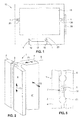
- Fig. 1 shows components of an elevator installation 15 in cross section.
- the elevator installation 15 comprises an elevator car 16 and guide rails 1.
- the elevator installation 15 can additionally comprise a counterweight 17, wherein both the elevator car 16 and the counterweight 17 in the elevator installation 15 are components to be guided.
- Each component to be guided is arranged to be movable on the guide rails 1 assigned to it.
- the guide rails 1 for guiding the elevator car 16 are fastened directly to a shaft wall 18 in the present embodiment variant.
- the guide rails 1 for guiding the counterweight 17 are fastened to a support frame of a support structure 19, the support structure 19 being fastened to the shaft wall 18.
- With 20 symbolic guide shoes for guiding the elevator car 16 or the counterweight 17 to the guide rails 1 are designated.
- a guide rail 1 for an elevator system which comprises a mounting base 2 with a planar mounting surface 4 and a guide portion 3.
- the guide rail 1 is made as a profile rail of a solid profile, has a T-shaped profile and is mirror-symmetrical with respect to a plane of symmetry S.
- the guide region has at its free end three guide surfaces 6, 6 'and 6 "(see Fig. 4 ) on.
- the guide surface 6 ' is parallel to the mounting surface 4.
- the guide surfaces 6 and 6 " are mutually parallel and perpendicular to the mounting surface 4 and the guide surface 6 'is arranged.
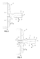
- the mounting base 2 has a groove 5, which extends over the entire length (direction F3) of the guide rail 1.
- the groove 5 has a substantially T-shaped cross-section. Viewed from the attachment surface 4 in the direction of the guide region 3, the groove 5 has a narrow portion with parallel side surfaces and a wider portion with a rectangular cross section for forming a rectangular cavity.
- the guide rail 1 can be fastened to a support structure 9 by engaging behind the groove 5 by means of a fastening element (cf. Fig. 4 ).
- the attachment is in the Fig. 4 shown schematically.
- the fastening element 7 is inserted into an opening 12 of the support structure 9 and into the groove 5 of the guide rail 1.
- the fastening element 7 can already be mounted on the support structure before the guide rail 1 is positioned.
- the fastening element 7 comprises a gripping portion 10 and a fixing portion 8, which is provided here with an external thread.
- the gripping portion 10 is shaped so that it can be inserted through the groove 5 and after rotation by 90 ° about its own axis (which is in this case in the plane of symmetry S), the groove 5 engages behind.
- a region 14 is provided with two parallel surfaces, which can be connected, for example, with a wrench. The orientation of the surfaces also shows whether the gripping portion 10 engages behind the groove or not. In this case, the surfaces are parallel to the plane of symmetry S when the gripping portion 10 engages behind the groove 5.
- a nut 13 is then screwed onto the mounting portion and secured by a lock nut 11.
- Such an arrangement thus enables the form-fitting attachment of the guide rail 1 with the support structure 9.
- the fastening means 7 positive connection in the directions F1 and F2 and depending on the tensile force in the direction F3 is generated (see also Fig. 2 ).
- This allows the precise adjustment of a frictional force in the direction F3, so that, for example, the guide rail 1 can slide along the direction F3 and thus can not be moved or even deformed during a shrinkage / expansion of the support structure 9.
- Fig. 5 shows an embodiment for a guide rail 1, which is attached directly to a shaft wall.
- the fastening means 7 are firmly attached to the shaft wall (not shown).
- the fastening means 7 has a fastening portion 8 and a subsequent thereto gripping portion 10.
- the gripping portion 10 is exemplified cylindrically shaped and adapted to the dimensions of the rectangular cavity of the groove 5.
- the diameter of the gripping portion 10 thus corresponds approximately to the width of the direction indicated by dashed straight lines cavity of the groove 5.
- the mounting portion 8 has evidentially a smaller diameter.
- the guide rail 1 have insertion openings 21, via which the respective gripping section 10 of the fastening means 7 can be inserted into the groove and then positively connected by displacement in the direction of travel with the groove.
Landscapes
- Lift-Guide Devices, And Elevator Ropes And Cables (AREA)
Abstract
Führungsschiene (1) für eine Aufzugsanlage, wobei die Führungsschiene (1) als Längsprofil mit einem im Wesentlichen T-förmigen Querschnitt aus einem Sockel (2) und einem senkrecht dazu angeordneten Führungsbereich (3) ausgebildet ist, dadurch gekennzeichnet, dass der Sockel (2) an seiner, dem Führungsbereich (3) abgewandten Befestigungsfläche (4) wenigstens eine hinterschnittene Nut (5) aufweist.Guide rail (1) for an elevator installation, wherein the guide rail (1) as a longitudinal profile with a substantially T-shaped cross section of a base (2) and a guide portion (3) arranged perpendicular thereto, characterized in that the base (2 ) at its, the guide region (3) facing away from mounting surface (4) has at least one undercut groove (5).
Description
Die Erfindung betrifft eine Führungsschiene für eine Aufzugsanlage nach dem Oberegriff des Anspruchs 1. Die Erfindung betrifft ferner ein Befestigungsmittel für eine solche Führungsschiene.The invention relates to a guide rail for an elevator system according to the upper handle of
Führungsschienen sind auf dem Gebiet der Aufzugsanlagen bekannt und werden zum Führen von Aufzugskabinen und/oder Gegengewichten in Verfahrrichtung verwendet. Eine Führungsschiene ist in der Regel als Vollprofil ausgebildet und weist einen Führungsbereich und einen Befestigungssockel auf. Der Führungsbereich wirkt dann mit einem Führungsschuh der Aufzugskabine oder des Gegengewichts zusammen. Der Befestigungssockel weist meistens eine dem Führungsbereich abgewandte, plane Befestigungsfläche auf, welche der korrekten Positionierung der Führungsschiene dient. Die Führungsschiene wird seitlich über Greifkrallen indirekt oder direkt an der Aufzugsschachtwand eines Gebäudes befestigt.Guide rails are known in the field of elevator installations and are used to guide elevator cars and / or counterweights in the direction of travel. A guide rail is generally formed as a solid profile and has a guide portion and a mounting base. The guide area then interacts with a guide shoe of the elevator car or the counterweight. The mounting base usually has a plane facing away from the guide area, planar mounting surface, which serves for the correct positioning of the guide rail. The guide rail is attached laterally via gripping claws indirectly or directly to the elevator shaft wall of a building.
Nachteilig bei einer solchen Befestigung der Führungsschiene ist, dass durch Gebäudesetzung und thermische Ausdehnung/Schrumpfung des Gebäudes in Verfahrrichtung verlaufende und auf die Führungsschiene wirkende Reibkräfte auftreten können, die unerwünscht sind. Zudem sind aufgrund der grossen Fertigungstoleranzen der Führungsschiene und der Greifkrallen die Kräfte nur sehr ungenau einstellbar.The disadvantage of such an attachment of the guide rail is that frictional forces that occur due to building set and thermal expansion / contraction of the building in the direction of travel and that act on the guide rail can occur, which are undesirable. In addition, the forces are only very inaccurate adjustable due to the large manufacturing tolerances of the guide rail and the gripping claws.
Es ist daher Aufgabe der Erfindung, eine Führungsschiene zu entwickeln, welche die Nachteile des Bekannten nicht aufweist, insbesondere eine Befestigungsmöglichkeit mit niedrigen Toleranzen bietet und Reibkräfte verringert oder gar vermeidet vermeidet.It is therefore an object of the invention to develop a guide rail, which does not have the disadvantages of the known, in particular provides a mounting option with low tolerances and reduces or even avoids frictional forces.
Die Aufgabe wird mit einer Führungsschiene gemäss Kennzeichen des unabhängigen Anspruchs 1 gelöst. Die Führungsschiene ist als Längsprofil mit einem bevorzugt im Wesentlichen T-förmigen Querschnitt aus einem Sockel und einem senkrecht dazu angeordneten Führungsbereich ausgebildet. Besonders bevorzugt ist die Führungsschiene als Vollprofil ausgebildet. Eine solche Ausbildung entspricht im Wesentlichen einer aus dem Stand der Technik bekannten Führungsschiene. Erfindungsgemäss weist der Sockel an seiner dem Führungsbereich abgewandten Befestigungsfläche wenigstens eine hinterschnittene Nut auf. Die Befestigungsfläche ist bevorzugt plan ausgebildet, so dass diese zur Ausrichtung der Führungsschiene verwendet werden kann. Die hinterschnittene Nut erlaubt somit die Befestigung der Führungsschiene an einem Gebäude oder dgl. Zudem wird bevorzugt die Nut maschinell gefertigt und bietet somit eine Befestigungsschnittstelle mit niedrigen Toleranzen.The object is achieved with a guide rail according to the characterizing part of the
Die Nut weist bevorzugt einen T-förmigen Querschnitt auf. Diese T-Nut kann einen sich in Verfahrrichtung erstreckenden Hohlraum aufweisen, der im Querschnitt rechteckig ist. An den rechteckigen Bereich schliesst in Richtung der Befestigungsfläche ein verjüngter Bereich an, wodurch der Hohlraum zur Befestigungsfläche hin offen ausgestaltet ist und das T gebildet wird. Andere Formgebungen für die Nut sind aber auch vorstellbar. So könnte die Nut einen sich in Verfahrrichtung erstreckenden trapezförmigen oder rautenförmigen Hohlraum aufweisen, der gegen die Befestigungsfläche hin offen ausgestaltet ist.The groove preferably has a T-shaped cross-section. This T-slot may have a extending in the direction of travel cavity which is rectangular in cross-section. A tapered region adjoins the rectangular area in the direction of the attachment surface, as a result of which the cavity is designed to be open towards the attachment surface and the T is formed. Other shapes for the groove are also conceivable. Thus, the groove could have a trapezoidal or diamond-shaped cavity extending in the direction of travel, which cavity is designed to be open towards the fastening surface.
Bevorzugt erstreckt sich die Nut über die gesamte Länge der Führungsschiene. Die Längsrichtung der Führungsschiene entspricht der Verfahrrichtung der Aufzugskabine oder des Gegengewichts der Aufzugsanlage. Eine solche Ausführungsform ist besonders vorteilhaft in der Fertigung und in der Montage. Insbesondere bei der Montage muss nicht notwendigerweise geachtet werden, - in Bezug auf die Verfahrrichtung i- n welchen Abschnitten sich die Nut befindet.Preferably, the groove extends over the entire length of the guide rail. The longitudinal direction of the guide rail corresponds to the direction of travel of the elevator car or the counterweight of the elevator installation. Such an embodiment is particularly advantageous in manufacturing and assembly. In particular during assembly, it is not necessary to take care of - with respect to the direction of travel in which sections the groove is located.
Bevorzugt ist ein Querschnitt der Führungsschiene spiegelsymmetrisch ausgebildet. Dabei verläuft bevorzugt eine Symmetrieebene im Wesentlichen senkrecht zur Befestigungsfläche.Preferably, a cross section of the guide rail is formed mirror-symmetrically. In this case, a plane of symmetry preferably runs essentially perpendicular to the fastening surface.
Bevorzugt weist der Sockel bzw. die Befestigungsfläche der Führungsschiene nur eine Nut auf. Aufgrund der Symmetrie ist die Nut mittig der Befestigungsfläche angeordnet und erlaubt eine sehr genaue Befestigung.Preferably, the base or the mounting surface of the guide rail has only one groove. Due to the symmetry, the groove is arranged centrally of the mounting surface and allows a very accurate attachment.
Der Führungsbereich weist bevorzugt an seinem freien Ende wenigstens zwei Führungsflächen auf, welche bevorzugt parallel zueinander verlaufen. Besonders bevorzugt weist der Führungsbereich an seinem freien Ende drei Führungsflächen auf, wobei eine Führungsfläche im Wesentlichen parallel zur Befestigungsfläche ausgebildet ist und die übrigen zwei Führungsflächen senkrecht dazu ausgebildet sind. Diese besondere Ausbildung der Führungsflächen erlaubt eine sehr genaue und im Wesentlichen spielfreie Führung von Führungs- oder Gleitschuhen entlang der Führungsschiene.The guide region preferably has at its free end at least two guide surfaces, which preferably extend parallel to one another. Particularly preferably, the guide region has at its free end three guide surfaces, wherein a guide surface is formed substantially parallel to the mounting surface and the rest two guide surfaces are formed perpendicular thereto. This special design of the guide surfaces allows a very accurate and essentially play-free guidance of guide or sliding shoes along the guide rail.
Es ist ferner Aufgabe der Erfindung ein Befestigungsmittel, welches eine schnelle und zuverlässige Befestigung der erfindungsgemässen Führungsschiene erlaubt. Die Aufgabe wird dadurch gelöst, dass das Befestigungsmittel einen Greifabschnitt aufweist, welcher im bestimmungsgemässen, montierten Zustand in die Nut einfügbar ist und die Nut hintergreift. Da die Nut der Führungsschiene hinterschnitten ist, kann mit einem erfindungsgemässen Befestigungsmittel die Nut hintergriffen werden und somit die Führungsschiene an einer Trägerkonstruktion, welche direkt ein Gebäude oder eine Rahmenkonstruktion eines Aufzugsschachtes sein kann, befestigt werden. Ferner kann das Befestigungsmittel einen Befestigungsabschnitt zur Befestigung an einer Trägerkonstruktion oder an eine Schachtwand des Aufzugsschachts aufweisen.It is a further object of the invention to provide a fastening means which permits a fast and reliable fastening of the guide rail according to the invention. The object is achieved in that the fastening means has a gripping portion which can be inserted in the intended, assembled state in the groove and engages behind the groove. Since the groove of the guide rail is undercut, with a fastening means according to the invention, the groove can be engaged behind and thus the guide rail to a support structure, which may be directly a building or a frame structure of a hoistway attached. Furthermore, the fastening means may have a fastening portion for attachment to a support structure or to a shaft wall of the elevator shaft.
Der Befestigungsabschnitt ist bevorzugt mit weiteren Mitteln versehen, beispielsweise mit einem Gewinde, welche eine Befestigung an der Trägerkonstruktion oder an die Schachtwand erlauben.The attachment portion is preferably provided with further means, for example with a thread, which allow attachment to the support structure or to the shaft wall.
Das Befestigungsmittel kann ein- oder mehrteilig ausgebildet sein.The fastening means may be formed in one or more parts.
Bevorzugt kann der Greifabschnitt bezüglich des Befestigungsabschnittes, drehbar ausgestaltet sein, so dass die Nut hintergreifbar ist. Der Greifabschnitt weist eine entsprechende dreidimensionale Gestalt auf, welche das Einfügen in die Nut vor der Drehung und das Hintergreifen nach der Drehung ermöglicht. Beispielsweise kann der Greifabschnitt mit einem im Wesentlichen T-förmigen Drehkopf versehen sein. Zum Hintergreifen der Nut wird dann das Befestigungsmittel oder nur der Greifabschnitt gedreht. Alternativ zum erwähnten drehbaren Greifabschnitt könnte das Befestigungsmittel auch auf andere Art und Weise mit der Führungsschiene verbunden werden. Beispielsweise könnte das Befestigungsmittel Rastelemente zum rastenden Verbinden an die Führungsschiene aufweisen. Die Rastelemente könnten derart ausgestaltet sein, dass sie beim Einfügen in die Nut zusammengedrückt werden und dann mit einer Rastnase die Nut hintergreifen.Preferably, the gripping portion with respect to the attachment portion, be designed to be rotatable, so that the groove is engaged behind. The gripping portion has a corresponding three-dimensional shape which allows insertion into the groove prior to rotation and engagement behind rotation. For example, the gripping portion may be provided with a substantially T-shaped turret. For engaging behind the groove, the fastening means or only the gripping portion is then rotated. As an alternative to the aforementioned rotatable gripping section, the fastening means could also be connected to the guide rail in a different manner. For example, the fastening means could comprise latching elements for latching connection to the guide rail. The locking elements could be designed such that they are compressed when inserted into the groove and then engage behind the groove with a latching lug.
Mit einem drehbaren Greifabschnitt sind bevorzugt Mittel zum Verbinden des Greifabschnittes mit dem Befestigungsabschnitt nach der Drehung ausgebildet. Diese Mittel können beispielsweise als Mutter mit Kontermutter ausgebildet sein. Ferner kann auch eine Bohrung ausgebildet sein, welche durch Einfügen eines Splintes oder Bolzens den Greifabschnitt drehfest mit dem Befestigungsabschnitt verbindet. Auch selbsttätige Mittel sind denkbar. Dabei kann der Greifabschnitt und/oder der Befestigungsabschnitt mit Rastmitteln versehen werden, welche beim Drehen einrasten und eine drehfeste Verbindung ausbilden. Bevorzugt sind die Rastmittel betätigbar, so dass bei einer Demontage der Führungsschiene diese von der Trägerkonstruktion wieder entfernbar ist.With a rotatable gripping portion are preferably means for connecting the gripping portion formed with the attachment portion after the rotation. These means may be formed for example as a nut with lock nut. Furthermore, a bore can also be formed, which rotatably connects the gripping section with the attachment section by inserting a split pin or bolt. Even automatic means are conceivable. In this case, the gripping portion and / or the fixing portion may be provided with locking means which engage upon rotation and form a rotationally fixed connection. Preferably, the latching means are actuated, so that when disassembling the guide rail, this is again removed from the support structure.
Eine weitere besondere Ausführungsform sieht vor, dass durch Querschnittsformänderung des Greifabschnittes, insbesondere durch Querschnittserweiterung, die Nut hintergreifbar ist. Dabei ist bevorzugt der Greifabschnitt nach der Art eines Hohlraumdübels ausgebildet, so dass beim Stauchen des Greifabschnittes Teile davon gespreizt werden und somit die Nut hintergreifbar ist. Möglich ist auch eine Ausbildung des Greifabschnittes nach Art eines Blindniets mit mechanischer, pneumatischer, hydraulischer oder pyrotechnischer Betätigung.A further particular embodiment provides that the groove can be engaged behind by changing the shape of the cross section of the gripping section, in particular by extending the cross-section. In this case, the gripping portion is preferably designed in the manner of a cavity plug, so that when upsetting the gripping portion parts thereof are spread and thus the groove is engaged behind. It is also possible to form the gripping section in the manner of a blind rivet with mechanical, pneumatic, hydraulic or pyrotechnic actuation.
Die Erfindung wird nachfolgend anhand von Ausführungsbeispielen in Verbindung mit den Zeichnungen beschrieben. Es zeigen:
- Fig. 1
- eine Aufzugsanlage mit Führungsschienen im Querschnitt;
- Fig. 2
- eine perspektivische Ansicht einer erfindungsgemässen Führungsschiene;
- Fig. 3
- eine Schnittansicht durch die Führungsschiene der
Fig. 2 ; - Fig. 4
- eine Schnittansicht durch die Führungsschiene der
Fig. 2 mit eingesetztem Befestigungsmittel; - Fig. 5
- eine Rückansicht auf eine Führungsschiene mit eingesetztem Befestigungsmittel gemäss einem zweiten Ausführungsbeispiel.
- Fig. 1
- an elevator system with guide rails in cross section;
- Fig. 2
- a perspective view of an inventive guide rail;
- Fig. 3
- a sectional view through the guide rail of
Fig. 2 ; - Fig. 4
- a sectional view through the guide rail of
Fig. 2 with inserted fastener; - Fig. 5
- a rear view of a guide rail with inserted fastener according to a second embodiment.
In
Der Führungsbereich weist an seinem freien Ende drei Führungsflächen 6, 6' und 6" (siehe
Der Befestigungssockel 2 weist eine Nut 5 auf, welche sich über die gesamte Länge (Richtung F3) der Führungsschiene 1 erstreckt. Die Nut 5 weist einen im Wesentlichen T-förmigen Querschnitt auf. Ausgehend von der Befestigungsfläche 4 in Richtung des Führungsbereichs 3 betrachtet, weist die Nut 5 einen schmalen Abschnitt mit parallelen Seitenflächen und einen breiteren Abschnitt mit rechteckigem Querschnitt zum Bilden eines rechteckigen Hohlraums auf. Dadurch ist die Führungsschiene 1 an einer Trägerkonstruktion 9 durch Hintergreifen der Nut 5 mittels eines Befestigungselements befestigbar (vgl. nachfolgende
Die Befestigung ist in der
Das Befestigungselement 7 umfasst einen Greifabschnitt 10 und einen Befestigungsabschnitt 8, welcher hier mit einem Aussengewinde versehen ist. Der Greifabschnitt 10 ist so geformt, dass er durch die Nut 5 einfügbar ist und nach Drehung um 90° um die eigene Achse (welche in diesem Fall in der Symmetrieebene S liegt) die Nut 5 hintergreift. Zum Drehen des Befestigungselements 7 ist ein Bereich 14 mit zwei parallelen Flächen vorgesehen, welche beispielsweise mit einem Schraubenschlüssel verbunden werden können. Die Orientierung der Flächen zeigt auch, ob der Greifabschnitt 10 die Nut hintergreift oder nicht. In diesem Fall sind die Flächen parallel zur Symmetrieebene S, wenn der Greifabschnitt 10 die Nut 5 hintergreift. Zur Befestigung wird dann eine Schraubenmutter 13 auf den Befestigungsabschnitt geschraubt und durch eine Kontermutter 11 gesichert.The
Eine solche Anordnung ermöglicht somit die formschlüssige Befestigung der Führungsschiene 1 mit der Trägerkonstruktion 9. Durch das Befestigungsmittel 7 wird Formschluss in die Richtungen F1 und F2 und je nach Zugkraft auch in Richtung F3 erzeugt (vgl. auch
Claims (8)
Priority Applications (1)
| Application Number | Priority Date | Filing Date | Title |
|---|---|---|---|
| EP15177558.2A EP3121141A1 (en) | 2015-07-20 | 2015-07-20 | Guide rail for a lift facility |
Applications Claiming Priority (1)
| Application Number | Priority Date | Filing Date | Title |
|---|---|---|---|
| EP15177558.2A EP3121141A1 (en) | 2015-07-20 | 2015-07-20 | Guide rail for a lift facility |
Publications (1)
| Publication Number | Publication Date |
|---|---|
| EP3121141A1 true EP3121141A1 (en) | 2017-01-25 |
Family
ID=53716389
Family Applications (1)
| Application Number | Title | Priority Date | Filing Date |
|---|---|---|---|
| EP15177558.2A Withdrawn EP3121141A1 (en) | 2015-07-20 | 2015-07-20 | Guide rail for a lift facility |
Country Status (1)
| Country | Link |
|---|---|
| EP (1) | EP3121141A1 (en) |
Cited By (4)
| Publication number | Priority date | Publication date | Assignee | Title |
|---|---|---|---|---|
| CN108328455A (en) * | 2018-04-04 | 2018-07-27 | 浙江蒂尔森电梯有限公司 | A kind of express elevator guide rail |
| DE102019200019A1 (en) * | 2019-01-03 | 2020-07-09 | Thyssenkrupp Ag | Elevator system with sliding transfer device |
| CN112239114A (en) * | 2019-07-16 | 2021-01-19 | 通力股份公司 | Elevator guide rail element |
| EP3842373A1 (en) * | 2019-12-23 | 2021-06-30 | Inventio AG | Elevator rail system for easy installation |
Citations (3)
| Publication number | Priority date | Publication date | Assignee | Title |
|---|---|---|---|---|
| ES2356204A1 (en) * | 2008-11-26 | 2011-04-06 | Orona, S.Coop | Guiding system for lifting appliances, elevator apparatus and method for mounting this guidance system. (Machine-translation by Google Translate, not legally binding) |
| WO2012087295A1 (en) * | 2010-12-21 | 2012-06-28 | Otis Elevator Company | Sheet metal elevator rail connector |
| CN203806903U (en) * | 2014-04-10 | 2014-09-03 | 马拉兹(江苏)电梯导轨有限公司 | T-shaped elevator guide rail |
-
2015
- 2015-07-20 EP EP15177558.2A patent/EP3121141A1/en not_active Withdrawn
Patent Citations (3)
| Publication number | Priority date | Publication date | Assignee | Title |
|---|---|---|---|---|
| ES2356204A1 (en) * | 2008-11-26 | 2011-04-06 | Orona, S.Coop | Guiding system for lifting appliances, elevator apparatus and method for mounting this guidance system. (Machine-translation by Google Translate, not legally binding) |
| WO2012087295A1 (en) * | 2010-12-21 | 2012-06-28 | Otis Elevator Company | Sheet metal elevator rail connector |
| CN203806903U (en) * | 2014-04-10 | 2014-09-03 | 马拉兹(江苏)电梯导轨有限公司 | T-shaped elevator guide rail |
Cited By (5)
| Publication number | Priority date | Publication date | Assignee | Title |
|---|---|---|---|---|
| CN108328455A (en) * | 2018-04-04 | 2018-07-27 | 浙江蒂尔森电梯有限公司 | A kind of express elevator guide rail |
| CN108328455B (en) * | 2018-04-04 | 2019-08-16 | 浙江蒂尔森电梯有限公司 | A kind of express elevator guide rail |
| DE102019200019A1 (en) * | 2019-01-03 | 2020-07-09 | Thyssenkrupp Ag | Elevator system with sliding transfer device |
| CN112239114A (en) * | 2019-07-16 | 2021-01-19 | 通力股份公司 | Elevator guide rail element |
| EP3842373A1 (en) * | 2019-12-23 | 2021-06-30 | Inventio AG | Elevator rail system for easy installation |
Similar Documents
| Publication | Publication Date | Title |
|---|---|---|
| EP2789772B1 (en) | Holder for a guide sleeve of a climbing system for concrete formwork | |
| DE3843737A1 (en) | LATCH HOLDER FOR A FACADE WALL CONSTRUCTION | |
| EP3472403B1 (en) | Device for fastening a panel-shaped component in a receiving groove of a carrying rail | |
| WO2019096537A1 (en) | Rail tongs | |
| EP3121141A1 (en) | Guide rail for a lift facility | |
| EP3302875B1 (en) | Device and method for positioning connection elements | |
| DE102015212274A1 (en) | Holder and framework with such a holder | |
| DE3420857A1 (en) | Gripping apparatus with gripper jaw | |
| DE102011106436A1 (en) | Device for fixing component to another component, particularly automotive components, such as covering parts, has fixing sleeve with sleeve section, where sleeve head is formed to lie at sleeve section at upper surface of component | |
| DE102015113737B3 (en) | sensor | |
| EP3211164A1 (en) | Sliding door system | |
| EP3535824B1 (en) | Busbar holder and corresponding assembly | |
| EP3786405B1 (en) | Furniture drive for moving a movable furniture part | |
| DE1455895B2 (en) | Stake sleeve for trucks | |
| EP3078785B1 (en) | Attachment device | |
| EP2853670B1 (en) | Guide rail for a sliding door | |
| DE202014101811U1 (en) | Brake pad holder, in particular for wheel brake discs of rail vehicles | |
| EP2881596B1 (en) | Mounting wedge | |
| EP2743417A1 (en) | Dowel device for fixing insulation material | |
| DE102011013828A1 (en) | Panel transfer and vehicle with a movable and a fixed body with a fairing transition | |
| DE202014100774U1 (en) | Door sealing device | |
| EP2914891B1 (en) | Mechanism for releaseably arresting a predeterminable state of a device, and safety switch having such a mechanism | |
| DE102016109081A1 (en) | An anchor device for fixing a plate member, plate assembly for cladding walls with the anchoring device, and a method for replacing the plate member of the plate assembly | |
| EP3088639A1 (en) | Device for aligning fitting parts opposite from each other | |
| DE102023103600A1 (en) | TOOL HOLDING DEVICE, TOOL CHANGING DEVICE AND METHOD FOR CHANGING TOOLS |
Legal Events
| Date | Code | Title | Description |
|---|---|---|---|
| PUAI | Public reference made under article 153(3) epc to a published international application that has entered the european phase |
Free format text: ORIGINAL CODE: 0009012 |
|
| AK | Designated contracting states |
Kind code of ref document: A1 Designated state(s): AL AT BE BG CH CY CZ DE DK EE ES FI FR GB GR HR HU IE IS IT LI LT LU LV MC MK MT NL NO PL PT RO RS SE SI SK SM TR |
|
| AX | Request for extension of the european patent |
Extension state: BA ME |
|
| STAA | Information on the status of an ep patent application or granted ep patent |
Free format text: STATUS: THE APPLICATION IS DEEMED TO BE WITHDRAWN |
|
| 18D | Application deemed to be withdrawn |
Effective date: 20170726 |