JP6760972B2 - Devices and methods for positioning coupling members - Google Patents
Devices and methods for positioning coupling members Download PDFInfo
- Publication number
- JP6760972B2 JP6760972B2 JP2017562739A JP2017562739A JP6760972B2 JP 6760972 B2 JP6760972 B2 JP 6760972B2 JP 2017562739 A JP2017562739 A JP 2017562739A JP 2017562739 A JP2017562739 A JP 2017562739A JP 6760972 B2 JP6760972 B2 JP 6760972B2
- Authority
- JP
- Japan
- Prior art keywords
- lever
- coupling member
- slider
- arm
- area
- Prior art date
- Legal status (The legal status is an assumption and is not a legal conclusion. Google has not performed a legal analysis and makes no representation as to the accuracy of the status listed.)
- Active
Links
- 230000008878 coupling Effects 0.000 title claims description 123
- 238000010168 coupling process Methods 0.000 title claims description 123
- 238000005859 coupling reaction Methods 0.000 title claims description 123
- 238000000034 method Methods 0.000 title description 8
- 230000000903 blocking effect Effects 0.000 claims description 70
- 230000013011 mating Effects 0.000 description 4
- 230000004913 activation Effects 0.000 description 1
- 230000002146 bilateral effect Effects 0.000 description 1
- 238000007664 blowing Methods 0.000 description 1
- 238000006073 displacement reaction Methods 0.000 description 1
- 230000008569 process Effects 0.000 description 1
Images
Classifications
-
- B—PERFORMING OPERATIONS; TRANSPORTING
- B23—MACHINE TOOLS; METAL-WORKING NOT OTHERWISE PROVIDED FOR
- B23P—METAL-WORKING NOT OTHERWISE PROVIDED FOR; COMBINED OPERATIONS; UNIVERSAL MACHINE TOOLS
- B23P19/00—Machines for simply fitting together or separating metal parts or objects, or metal and non-metal parts, whether or not involving some deformation; Tools or devices therefor so far as not provided for in other classes
- B23P19/04—Machines for simply fitting together or separating metal parts or objects, or metal and non-metal parts, whether or not involving some deformation; Tools or devices therefor so far as not provided for in other classes for assembling or disassembling parts
- B23P19/06—Screw or nut setting or loosening machines
- B23P19/062—Pierce nut setting machines
-
- B—PERFORMING OPERATIONS; TRANSPORTING
- B23—MACHINE TOOLS; METAL-WORKING NOT OTHERWISE PROVIDED FOR
- B23P—METAL-WORKING NOT OTHERWISE PROVIDED FOR; COMBINED OPERATIONS; UNIVERSAL MACHINE TOOLS
- B23P19/00—Machines for simply fitting together or separating metal parts or objects, or metal and non-metal parts, whether or not involving some deformation; Tools or devices therefor so far as not provided for in other classes
- B23P19/001—Article feeders for assembling machines
- B23P19/006—Holding or positioning the article in front of the applying tool
-
- B—PERFORMING OPERATIONS; TRANSPORTING
- B23—MACHINE TOOLS; METAL-WORKING NOT OTHERWISE PROVIDED FOR
- B23P—METAL-WORKING NOT OTHERWISE PROVIDED FOR; COMBINED OPERATIONS; UNIVERSAL MACHINE TOOLS
- B23P19/00—Machines for simply fitting together or separating metal parts or objects, or metal and non-metal parts, whether or not involving some deformation; Tools or devices therefor so far as not provided for in other classes
- B23P19/001—Article feeders for assembling machines
- B23P19/007—Picking-up and placing mechanisms
-
- B—PERFORMING OPERATIONS; TRANSPORTING
- B21—MECHANICAL METAL-WORKING WITHOUT ESSENTIALLY REMOVING MATERIAL; PUNCHING METAL
- B21J—FORGING; HAMMERING; PRESSING METAL; RIVETING; FORGE FURNACES
- B21J15/00—Riveting
- B21J15/10—Riveting machines
- B21J15/30—Particular elements, e.g. supports; Suspension equipment specially adapted for portable riveters
- B21J15/32—Devices for inserting or holding rivets in position with or without feeding arrangements
Landscapes
- Engineering & Computer Science (AREA)
- Mechanical Engineering (AREA)
- Automatic Assembly (AREA)
- Labeling Devices (AREA)
- Moulds For Moulding Plastics Or The Like (AREA)
- Insertion Pins And Rivets (AREA)
Description
本発明は、結合部材を位置決めする装置と方法に関するものであって、結合部材は送り装置によって引き取り領域から接合装置のための引き渡し領域へ移動可能であり、かつ阻止装置が阻止位置において、引き取り領域から引き渡し領域への結合部材の移動を阻止する。本発明は、さらに、結合部材をセットする方法に関する。 The present invention relates to a device and method for positioning a coupling member, the coupling member can be moved from a pick-up area to a delivery area for the joining device by a feeding device, and the blocking device is in a blocking position, a pick-up area. Prevents the movement of the coupling member from to the delivery area. The present invention further relates to a method of setting a coupling member.
結合部材は、たとえば圧入ボルトであり、あるいはたとえば特許文献1から知られた接合部材である。これらの結合部材は、ヘッドとシャフトを有し、シャフトは、ある形態においてはねじを有し、他の形態においては切断尖端を有している。その代わりに、あるいはそれに加えて、ヘッドの下方に一周する凹部が形成されており、その凹部が結合部材を構成部品又はアッセンブリと軸方向に堅固に結合するために用いられ、その中へ結合部材が圧入される。
The joining member is, for example, a press-fit bolt, or, for example, a joining member known from
圧入ボルトを圧入するための方法と装置が、たとえば特許文献2から知られている。
Methods and devices for press-fitting press-fitting bolts are known, for example, from
本発明の課題は、接合装置、たとえばセッティングピストンのために、定められた時点で高い精度での結合装置の位置決めを実現することである。 An object of the present invention is to achieve highly accurate positioning of a coupling device at a defined time point for a joining device, such as a setting piston.
第1の視点によれば、送り装置と、少なくとも阻止位置と解放位置との間で揺動可能な少なくとも1つのレバーを備えた阻止装置とを有する、結合部材を位置決めする装置が形成され、結合部材が送り装置によって引き取り領域から接合装置のための引き渡し領域内へ移動可能であり、少なくとも1つのレバーが阻止位置と解放位置の間で揺動可能であって、少なくとも1つのレバーが阻止位置において、引き取り領域から引き渡し領域内への結合部材の移動を阻止し、少なくとも1つのレバーに対して変位可能な少なくとも1つの終端ストッパが設けられており、その終端ストッパによって阻止位置から解放位置への少なくとも1つのレバーの移動が阻止可能であり、少なくとも1つのレバーが第1のアームと第2のアームとを有する両側のレバーとして形成されており、かつ少なくとも1つのレバーの第1のアームが、阻止位置から解放位置への少なくとも1つのレバーの移動を阻止するために、少なくとも1つの終端ストッパと協働し、少なくとも1つのレバーの第2のアームは阻止位置において結合部材のための保持ジョーとして機能する。 According to a first aspect, a device for positioning a coupling member is formed and coupled with a feeding device and a blocking device with at least one lever swingable between a blocking position and a release position. The member can be moved from the pick-up area into the delivery area for the joining device by the feed device, at least one lever can swing between the blocking and releasing positions, and at least one lever is in the blocking position. , At least one end stopper that prevents the coupling member from moving from the take-up area into the take-up area and is displaceable with respect to at least one lever is provided by the end stopper at least from the stop position to the release position. The movement of one lever can be blocked, at least one lever is formed as both side levers having a first arm and a second arm, and the first arm of at least one lever is blocking. In cooperation with at least one termination stopper to prevent the movement of at least one lever from position to release position, the second arm of at least one lever acts as a retaining jaw for the coupling member in the blocking position. To do.
結合部材は、たとえば圧縮空気によって引き取り領域内へ移送される。終端ストッパは、高い速度及び/又は高い運動エネルギをもって引き取り領域内へ進入する結合部材が阻止装置へ作用して、それを早期に、かつ/又は管理されずに解放位置へ移動させてしまうことを、阻止する。したがって終端ストッパは、結合部材が引き取り領域から引き渡し領域内へ管理されずに、かつ/又は早期に移動することを、阻止する。接合装置、たとえばセッティングピストンのための引き渡し領域への結合部材の移動は、送り装置によって行われ、この移動は、終端ストッパの移動後に初めて、あるいは移動によって可能になる。 The coupling member is transferred into the take-up area by, for example, compressed air. The termination stopper prevents the coupling member entering the take-up area at high speed and / or high kinetic energy from acting on the blocking device and moving it to the release position early and / or uncontrolled. , Stop. Thus, the termination stopper prevents the coupling member from moving unmanaged and / or prematurely from the pick-up area into the delivery area. The movement of the coupling member to the delivery area for the joining device, eg the setting piston, is performed by the feed device, which movement is possible only after or by movement of the termination stopper.
レバーが1つだけ設けられている限りにおいて、装置は、好ましくは適切な相手面を有しており、その相手面と阻止装置及び/又は終端ストッパが協働する。阻止装置を阻止位置に確保するために、1つのレバーのみを有する形態において、終端ストッパはレバーの第1のアームの内側に位置決めされる。それによってレバーの、第2のアームが外側へ揺動される揺動運動が阻止されて、結合部材はレバーの第2のアームと相手面との間に挟持可能である。 As long as only one lever is provided, the device preferably has a suitable mating surface with which the mating surface and the blocking device and / or termination stopper work together. In the form of having only one lever, the termination stopper is positioned inside the first arm of the lever to secure the blocking device in the blocking position. As a result, the swinging motion of the lever in which the second arm is swung outward is prevented, and the coupling member can be sandwiched between the second arm of the lever and the mating surface.
ある形態において、阻止装置は逆方向に揺動可能な2つの両側のレバーを有しており、レバーの第1のアームが、阻止位置から解放位置へのレバーの移動を阻止するために終端ストッパと協働し、かつレバーの第2のアームは結合部材のための保持ジョーとして機能する。レバーは、好ましくは中心線に対して対称に配置されている。阻止装置を阻止位置に確保するために、終端ストッパがレバーの2つの第1のアームの間へ移動されるので、2つの第1のアームが接近する、レバーの揺動運動が阻止される。そのようにして阻止部材は、レバーの2つの第2のアームの間に確実に挟持可能となる。 In some embodiments, the blocking device has two levers on both sides that can swing in opposite directions, and the first arm of the lever is a termination stopper to prevent the lever from moving from the blocking position to the releasing position. And the second arm of the lever acts as a holding jaw for the coupling member. The levers are preferably arranged symmetrically with respect to the centerline. Since the termination stopper is moved between the two first arms of the lever to secure the blocking device in the blocking position, the swinging motion of the lever as the two first arms approach is blocked. In this way, the blocking member can be reliably pinched between the two second arms of the lever.
ある形態において、少なくとも1つのレバーに、力部材、特にばね部材が対応づけられており、そのばね部材がレバーを阻止位置へ強制移動させる。力部材は少なくとも1つのレバーに支援するように作用するだけであるので、ばね力は、たとえば特許文献2から知られた装置におけるよりも、小さく寸法設計することが可能である。いくつかの形態においては、力部材は省かれる。
In some embodiments, at least one lever is associated with a force member, particularly a spring member, which forces the lever to move to a blocking position. Since the force member only acts to support at least one lever, the spring force can be sized smaller than, for example, in the device known from
ある形態においては、ガイド装置、たとえばガイドレールが設けられており、それに沿って結合部材が引き取り領域から引き渡し領域内へ摺動される。好ましい形態において、結合部材は送り装置によって1つのレバーの第2のアームに沿って、あるいは2つのレバーの第2のアームに沿って、引き渡し領域内へ摺動可能である。1つのレバーの第2のアーム又は2つのレバーの第2のアームは、この目的のために、好ましくはガイド面を有しており、たとえば、シャフトとヘッドを有する結合部材において、ヘッドの下側がガイド面上に載置され、シャフトはレバーの解放位置においてレバーの間−あるいはレバーとガイドレールの間−で案内されて、阻止位置に挟持される。 In some embodiments, a guide device, such as a guide rail, is provided along which the coupling member is slid from the take-up area into the take-up area. In a preferred embodiment, the coupling member is slidable by the feeder along the second arm of one lever or along the second arm of the two levers into the delivery area. The second arm of one lever or the second arm of two levers preferably has a guide surface for this purpose, eg, in a coupling member having a shaft and a head, the underside of the head. Mounted on the guide surface, the shaft is guided between the levers-or between the levers and the guide rails-at the lever release position and is held in the blocking position.
送り装置は、好ましくは、少なくとも1つのレバーに対して線形に摺動可能なスライダを有している。スライダは、たとえば、シャフトとヘッドを有する結合部材においては、結合部材の変位運動のためにシャフトに作用する。スライダの自由端部の形状は、好ましい形態において、結合部材の形状に適合されている。終端ストッパは、ある形態においては、スライダとは別に形成されており、終端ストッパとスライダの移動は、互いに調整されているので、スライダによって結合部材が変位移動する場合に阻止位置からの阻止装置の解放が保証されている。終端ストッパは、たとえばスライダとは逆に2つのレバーの間の領域又はレバーと相手面との間の領域から移動される。好ましい形態において、スライダの第1の部分が終端ストッパとして機能する。それによって付加的な駆動手段、ギア部材又は同種のものは、省くことができる。 The feed device preferably has a slider that is linearly slidable with respect to at least one lever. The slider acts on the shaft due to the displacement motion of the coupling member, for example, in a coupling member having a shaft and a head. The shape of the free end of the slider is, in a preferred form, adapted to the shape of the coupling member. In some forms, the termination stopper is formed separately from the slider, and the movement of the termination stopper and the slider is coordinated with each other, so that when the coupling member is displaced by the slider, the blocking device from the blocking position Release is guaranteed. The termination stopper is moved, for example, from the area between the two levers or the area between the lever and the mating surface, as opposed to the slider. In a preferred embodiment, the first portion of the slider functions as a termination stopper. Thereby, additional drive means, gear members or the like can be omitted.
スライダは、好ましくは、長手方向において第1の部分に対して離隔した第2の部分を有しており、第2の部分は、アンロック位置の通過後に解放位置へのレバーの揺動を可能にする形状を有している。言葉を変えると、たとえば2つのレバーの間へ導入されるスライダの横断面は一定である。スライダは、阻止装置に対して変位可能である。終端ストッパとして機能する第1の部分は、第1の位置において、レバーの第1のアームの間へ導入されるので、解放位置へのレバーの揺動は阻止されている。スライダが摺動する場合に、アンロック位置の通過後に第2の部分が2つの第2のアームの間へ達する。第2の部分は、解放位置へのレバーの揺動運動が可能であるように、形成されている。ある形態において、この目的のために、レバーの平面内におけるスライダの横断面は、第1の部分に対して第2の部分内で細くなっている。 The slider preferably has a second portion separated from the first portion in the longitudinal direction, the second portion allowing the lever to swing to the release position after passing the unlock position. Has a shape to make. In other words, for example, the cross section of the slider introduced between the two levers is constant. The slider is displaceable with respect to the blocking device. The first portion, which functions as a termination stopper, is introduced between the first arms of the lever at the first position, thus preventing the lever from swinging to the release position. When the slider slides, the second portion reaches between the two second arms after passing the unlock position. The second portion is formed so that the swinging motion of the lever to the release position is possible. In some embodiments, for this purpose, the cross section of the slider in the plane of the lever is tapered in the second portion relative to the first portion.
好ましい形態において、レバーの第1のアームは、スライダの操作ルート内へ突出する、終端ストッパと協働する突出部を有しており、好ましくは、第2の部分内でスライダの突出部へ向いた壁が溝を有している。それによって解放位置へのレバーの揺動運動が可能であり、同時に、スライダの溝に隣接する壁領域は、スライダのためのガイド面として残る。 In a preferred embodiment, the first arm of the lever has a protrusion that projects into the operating route of the slider and cooperates with the termination stopper, preferably towards the protrusion of the slider within the second portion. The wall that was there has a groove. This allows the lever to swing to the release position, while at the same time the wall area adjacent to the groove of the slider remains as a guide surface for the slider.
好ましい形態において、アイドルストロークにおいて、引き渡し領域の方向における送り装置の最大の操作移動は、結合部材の位置決めストロークにおいてよりも大きい。言葉を変えると、操作移動は結合装置によって制限されており、それに対してアイドルストロークにおいて、すなわち結合部材が挿入されることのない移動において、送り装置、特にスライダは、この終端位置を越えて移動される。スライダの移動は、センサ装置によって検出可能である。これが、簡単なやり方で引き渡し装置内の結合部材の存在を照会することを許し、そこに結合部材が存在する場合にだけ、接合装置の能動化が行われ、たとえばセッティングプロセスが作動される。 In a preferred embodiment, in the idle stroke, the maximum operational movement of the feeder in the direction of the delivery region is greater than in the positioning stroke of the coupling member. In other words, the operational movement is restricted by the coupling device, whereas in the idle stroke, i.e. in the movement where the coupling member is not inserted, the feeder, especially the slider, moves beyond this termination position. Will be done. The movement of the slider can be detected by the sensor device. This allows the presence of the coupling member in the delivery device to be queried in a simple manner, and only if the coupling member is present there is activation of the joining device, eg, the setting process is activated.
第2の視点によれば、結合部材を引き取り装置へ個々に供給するための供給装置と、引き渡し領域内に位置決めされた結合装置をセットするためのセッティングピストンと、結合部材を位置決めする装置とを有する、結合部材をセットする装置が形成され、結合部材を位置決めする装置は、結合部材を引き取り領域から引き渡し領域へ移動させることができる送り装置、阻止位置と解放位置との間で変位可能な少なくとも1つのレバーを備えた阻止装置及びレバーに対して変位可能な終端ストッパを有しており、レバーは阻止位置において引き取り領域からの結合部材の移動を阻止し、かつ終端ストッパが阻止位置から解放位置へのレバーの移動を阻止することができる。結合部材は、たとえば装置によって構成部品又はアッセンブリ内へ圧入あるいは挿入される。セッティングピストンは、ある形態において、その自由端部に装置を有しており、その装置によって結合部材がセッティングピストンに保持される。この目的のために、たとえば磁石又は吸引装置が設けられており、その吸引装置が結合部材を負圧によって固定する。好ましい形態においては、セッティングピストンに結合部材を保持するための機械的なクリップが設けられている。供給装置は、好ましくは、少なくとも1つの通路片を有する吹き込み装置として形成されており、結合部材は通路片を通して空気圧を吹き込まれる。結合部材を位置決めする装置に連続する通路片は、好ましくは湾曲されており、終端領域は引き取り領域内へ接線状に連通している。 According to the second viewpoint, a supply device for individually supplying the coupling member to the take-up device, a setting piston for setting the coupling device positioned in the delivery region, and a device for positioning the coupling member are provided. A device for setting the coupling member is formed, and the device for positioning the coupling member is a feeding device capable of moving the coupling member from the take-up area to the delivery area, at least displaceable between the blocking position and the releasing position. It has a blocking device with one lever and a displaceable termination stopper with respect to the lever, the lever blocking the movement of the coupling member from the take-up area at the blocking position, and the termination stopper being released from the blocking position. It is possible to prevent the movement of the lever to. The coupling member is press-fitted or inserted into the component or assembly by, for example, a device. The setting piston, in some form, has a device at its free end, which holds the coupling member to the setting piston. For this purpose, for example, a magnet or a suction device is provided, the suction device fixing the coupling member by negative pressure. In a preferred embodiment, the setting piston is provided with a mechanical clip for holding the coupling member. The feeding device is preferably formed as a blowing device having at least one passage piece, and the coupling member is blown with air pressure through the passage piece. The passage piece continuous with the device for positioning the coupling member is preferably curved and the termination region tangentially communicates into the take-up region.
第3の視点によれば、結合部材を位置決めする方法であって、結合部材が送り装置によって引き取り領域から接合部材のための引き渡し領域へ移動され、引き取り領域から引き渡し領域内への結合部材の移動が、阻止位置に配置された阻止装置の少なくとも1つのレバーによって阻止され、少なくとも1つのレバーが、結合部材を引き渡し領域へ移動させるために、解放位置へ移動される、ものにおいて、結合部材を引き取り領域内へ引き取る場合に、阻止位置から解放位置への少なくとも1つのレバーの移動が終端ストッパによって阻止され、少なくとも1つのレバーが第1のアームと第2のアームを有する両側のレバーとして形成されており、少なくとも1つのレバーの第1のアームが、結合部材を引き取り領域内へ引き取る場合に終端ストッパと協働するので、阻止位置から解放位置へのレバーの移動が阻止され、かつ引き取り領域から引き渡し領域内への結合部材の移動が、阻止装置の阻止位置に配置された少なくとも1つの両側レバーの第2のアームによって阻止される。 According to the third viewpoint, it is a method of positioning the coupling member, in which the coupling member is moved from the take-up region to the delivery region for the joint member by the feeding device, and the coupling member is moved from the take-up region to the delivery region. Is blocked by at least one lever of the blocking device located in the blocking position, and at least one lever is moved to the release position to move the coupling member to the delivery area, in which the coupling member is picked up. When pulling into the region, the movement of at least one lever from the blocking position to the releasing position is blocked by the termination stopper, and at least one lever is formed as a bilateral lever with a first arm and a second arm. The first arm of at least one lever cooperates with the termination stopper when pulling the coupling member into the pick-up area, thus preventing the lever from moving from the blocking position to the release position and delivering from the pick-up area. The movement of the coupling member into the region is blocked by the second arm of at least one side lever located at the blocking position of the blocking device.
本発明の他の特徴、詳細及び利点が、請求項と要約および本発明の好ましい実施形態についての以下の説明及び図面から明らかにされ、請求項と要約の文言は、参照によって明細書の内容とされる。実施例の一部として説明され、あるいは図示される特徴は、本発明の他の実施形態を得るために、他の実施例においても同様に使用することができる。 Other features, details and advantages of the invention will be apparent from the following description and drawings of the claims and abstracts and preferred embodiments of the invention, the wording of the claims and abstracts by reference with the contents of the specification. Will be done. Features described or illustrated as part of an embodiment can be similarly used in other embodiments to obtain other embodiments of the invention.
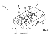
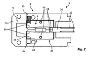
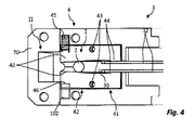
図1は、図1に示されていない接合装置又はセッティング装置のための引き渡し領域内で結合部材2を位置決めするための装置1を図式的に斜視図で示している。図2から6は、図1に示す装置1を、結合部材2を引き取る前、結合部材2を引き取り領域I内へ引き取る時、引き取り領域Iから引き渡し領域II内への結合部材2の移動の開始時、引き取り領域Iから引き渡し領域II内への結合部材2の移動の間、もしくは引き渡し領域II内への結合部材2の移動後において、切断して上面で示している。
FIG. 1 is a schematic perspective view of a
結合部材2は、ボルト形状にヘッドとシャフトを有している。
The
装置1は、送り装置3と阻止装置4を有している。図示される装置1は、さらに、支承プレート10を有しており、その支承プレートによって装置1を図示されない設備に取り付けることができる。支承プレート10は、ガイド斜面100を有しているので、供給装置6(図7を参照)によって供給された結合部材2が、引き取り領域Iの引き渡し領域IIを向いた端部内へ案内される。引き渡し領域II内では、結合部材2はセッティングピストン7(図7を参照)又は他の接合装置のために接近することができ、図示される実施例において、引き渡し領域IIはガイドレール70によって画成されている。
The
結合部材2は、送り装置3によって引き取り領域Iから引き渡し領域IIへ移動可能である。図示される送り装置3は、調節可能なスライダ30を有しており、そのスライダは、図4から6に示すように、結合部材2をスライドさせるために結合装置2のシャフトに作用する。スライダ30は、側面にそれぞれ長手方向に延びる溝32を有している。スライダ30は、ある形態においては、空気圧シリンダ34(図7を参照)によって変位することができる。空気圧シリンダの代わりに、代替的な駆動装置、たとえば油圧及び/又は電気式が考えられる。空気圧シリンダは、それぞれ要請に応じてシングル又はダブルで作用するように形成されている。見やすくするために、送り装置3の空気圧シリンダ30は、図1から6には示されていない。
The
阻止装置4によって、引き取り領域Iから引き渡し領域II内への結合部材2の移動を阻止することができる。阻止装置4は、この目的のために少なくとも1つのレバー40を有しており、引き取り領域Iから引き渡し領域II内への結合部材の移動は、阻止位置に配置されたレバー40によって阻止され、レバー40は、結合部材を引き渡し領域内へ移動させるために、解放位置へ移動される。
The
阻止装置4は、図示される実施例において、逆方向に揺動可能な2つの両側レバー40を有している。レバー40は、それぞれ第1のアーム41と第2のアーム42を有しており、かつ、第1と第2のアームの間に位置する軸を中心にピン43によって阻止位置と解放位置との間で揺動可能である。レバー40は、第1のアーム41にそれぞれ突出部44を有しており、その機能については後述する。レバー40には、それぞればね部材45が作用し、そのばね部材がレバー40を阻止位置へ強制移動させ、図2から6には、1つのばね部材45のみが示されている。ばね部材45は、レバー40もしくは支承プレート100に形成された該当する切り欠き46、102内へ挿入されている。
The
図示されるレバー40は、ダブル機能を有している。というのは、付加的に、結合部材2のヘッドへ向いた面が、スライダ30によって結合部材2が引き取り領域Iから引き渡し領域IIへ移動する場合のガイド面としても用いられるからである。結合部材2のシャフトは、レバー40の間に配置されている。他の形態において、結合部材2は、レバー40とは別に配置されたガイドレールに沿って移動される。
The
図3において認識できるように、レバー40は阻止位置において、引き取り領域Iから引き渡し領域IIの方向への結合部材2の移動を阻止する。この目的のために、レバー40の第2のアーム42の間隔は、少なくとも領域的に、結合部材2のシャフトの直径よりも小さい。図示される実施例において、第2のアーム42はそれぞれ、結合部材2のシャフトへ向いた面に進入斜面を有している。
As can be recognized in FIG. 3, the
レバー−40は、図1から3に示す阻止位置から、図5に示す解放位置へ揺動可能であり、その解放位置においては第2のアーム42の間隔はシャフト直径よりも大きく、かつ引き渡し領域IIの方向への結合部材2の移動が可能である。
The lever-40 can swing from the blocking position shown in FIGS. 1 to 3 to the releasing position shown in FIG. 5, and at the releasing position, the distance between the
本発明によれば、終端ストッパによって阻止位置から解放位置へのレバー40の移動が阻止可能であり、図示される実施例においては、スライダ30の第1の部分が終端ストッパとして機能する。
According to the present invention, the end stopper can prevent the
図1から3に示す状態において、スライダ30の第1の部分がレバー40の第1のアーム41の間へ導入されている。そのようにして終端ストッパとして機能する、スライダ30の第1の部分が、図1から3に示す阻止位置からのレバー40の揺動運動を阻止する。
In the state shown in FIGS. 1 to 3, the first portion of the
図示される実施例において、レバー40はそれぞれ突出部44を有しており、その突出部がスライダ30の操作ルート内へ突出し、かつ、阻止位置にレバー40を確保するためにスライダ30の側壁と協働する。
In the illustrated embodiment, each of the
結合部材2を引き渡し領域II内へ移動させるために、スライダ30は、スライダ30が結合部材2上へ接近移動されるように、駆動される。スライダ30は、レバー40に対してスライドされる。図4において認識できるように、スライダ30の、溝32を有する第2の部分が突出部44の領域内へ達する。溝32が、阻止位置から解放位置へのレバー40の揺動運動を許し、突出部44が溝32内へ導入される。
In order to move the
図4において認識できるように、ばね部材45がまずレバー40を阻止位置へ強制移動させるので、レバー40の移動はもはや阻止されているが、レバー40はまず阻止位置に留まり、さらに引き取り領域Iから引き渡し領域II内への結合部材2の移動を阻止する。スライダ30が結合部材2に、もっと正確にはそのシャフトに、作用するとすぐに、結合部材2が引き渡し領域IIの方向へ摺動され、レバー40はばね部材45の力に抗して、図5において認識できるように、解放位置へ強制移動される。
As can be recognized in FIG. 4, since the
スライダ30が図6に示す位置から図2に示す位置へ引き戻される場合に、ばね部材45がレバー40を阻止位置へ強制移動させるので、溝32内の突出部44の固着が阻止される。
When the
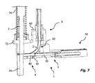
図7は、結合部材2を引き取り領域I(図2から6を参照)へ個々に供給するための供給装置6、引き渡し領域II(図2から6を参照)に位置決めされた結合部材2をセットするためのセッティングピストン7及び、送り装置2と阻止装置4を備えた、図1から6に示す装置1を有する、結合部材2をセットするための装置を示しており、装置1によって結合部材2が引き取り領域Iから引き渡し領域II内へ移動可能である。
FIG. 7 shows a supply device 6 for individually supplying the
支承プレート10には、供給装置6を接続するためのハウジング60と、セッティングピストン7のためのハウジング72が取り付けられている。供給装置6を接続するためのハウジング60は、通路片62を有しており、その通路片は結合部材2を位置決めするための装置1の引き取り領域内にほぼ接線状に連通している。
A housing 60 for connecting the supply device 6 and a
結合部材2は、通路片62を通して圧縮空気によって移送される。結合部材2は、図示される実施例において引き取り領域内に、シャフトが実質的に垂直に延びて、ヘッドがシャフトの上方に配置されるように、位置決めされている。
The
セッティングピストン7は、図示される実施例において、図示されない駆動装置によって復帰ばね74の力に抗して垂直方向にスライド可能である。セッティングピストン7の軸方向の延長上にガイド部材70が設けられており、そのガイド部材によってセッティングピストン7の移動が案内されている。セットするため、特に結合部材を圧入するために、セッティングピストン7はガイド部材70に沿って構成部品又はアッセンブリの方向へ移動可能である。他の形態においてはガイド部材は設けられておらず、セッティングピストン7はハウジング72によって案内される。
In the illustrated embodiment, the setting piston 7 is slidable in the vertical direction against the force of the
送り装置3は、説明したように、スライダ30を有しており、スライダ30は、駆動装置を形成する空気圧シリンダ34と機械的に結合されている。
As described, the
スライダ30は、その自由端部が引き渡し領域II(図2から6を参照)の方向へ移動されるように、駆動される。結合部材2が引き取り領域I(図2から6を参照)内に位置決めされている限りにおいて、結合部材は上述したように引き渡し領域II内へ移動される。送り装置3は、好ましくは次のように、すなわちアイドルストロークの場合、すなわち結合部材2を連動しない場合に、引き渡し領域IIの方向へのスライダの最大の操作移動が、結合部材2の位置決めストロークよりも大きいように、形成されている。ある形態において、この目的のために、結合部材2は位置決めストロークにおいて終端ストッパに接する終端位置へ移動され、それによってスライダ30のそれ以上の移動が阻止される。センサ装置によって、スライダ30が移動する場合に終端位置を通過したか、が検出可能である。センサ装置が終端位置を通過したことを検出した限りにおいて、アイドルストロークが検出されて、装置1は結合部材2を新たにセットするように駆動され、かつ/又はエラー報告が出力される。
The
それに対してセンサ装置によって、結合部材2が引き渡し領域IIへ移動されたことが検出された限りにおいて、スライダ30を引き戻して、結合部材2をセットするようにセッティングピストン7を駆動することができる。結合部材2をセッティングピストン7へ引き渡すために、ある形態において、セッティングピストン7は前方の端部にクリップを有しており、そのクリップが結合部材2をセッティングピストン7に保持する。
On the other hand, as long as the sensor device detects that the
図1から7に示す装置1の方向付けは単なる例であって、それぞれ要請に応じて他の方向付けが考えられ、阻止装置4のレバー40は、結合部材2のシャフトに対して平行に配置されて、結合部材2はシャフトに対して垂直になる平面に沿って送られる。
The orientation of the
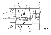
図8は装置1を、図1から6と同様に、結合部材2を引き取り領域I内に引き取る場合において切断して上面図で示している。図8に示す装置1は、図1から6に示す装置1に実質的に相当し、同一の構成部品には統一的な参照符号が使用される。すでに説明されている構成部品を新たに詳細に説明することは、省く。図1から6とは異なり、溝32が進入斜面36を有しており、その進入斜面が、スライダ30を図6に示す位置から図8に示す位置へ引き戻す場合にガイド溝32からの突出部44のガイドを許す。それによってばね部材45も省くことができる。変形例においては、ばね部材あるいは他の力部材が設けられており、それがレバー40を阻止位置へ強制移動させる。
なお、本願発明の実施形態として、以下の参考例も含まれる。
[参考例]
結合部材(2)を位置決めする方法であって、結合部材(2)が送り装置によって引き取り領域(I)から接合装置のための引き渡し領域(II)内へ移動され、前記引き取り領域(I)から前記引き渡し領域(II)内への前記結合部材(2)の移動が、阻止装置(4)の阻止位置に配置された少なくとも1つのレバー(40)によって阻止され、前記阻止装置(4)の前記少なくとも1つのレバー(40)が、前記結合部材(2)を前記引き渡し領域(II)へ移動させるために、解放位置へ移動される、ものにおいて、
前記結合部材(2)が前記引き取り領域内に引き取られる場合に、前記阻止位置から前記解放位置への前記少なくとも1つのレバー(40)の移動が、終端ストッパによって阻止され、
前記少なくとも1つのレバー(40)が、第1のアーム(41)と第2のアーム(42)を有する両側のレバー(40)として形成されており、
前記引き取り領域(I)内に前記結合部材(2)が引き取られる場合に、前記少なくとも1つのレバー(40)の第1のアーム(41)は前記終端ストッパと協働するので、前記阻止位置から前記解放位置への前記レバー(40)の移動が阻止され、かつ
前記引き取り領域(I)から前記引き渡し領域(II)内への前記結合部材(2)の移動が、前記阻止装置(4)の前記阻止位置に配置された前記少なくとも1つの両側のレバ−(40)の第2のアーム(42)によって阻止される、
ことを特徴とする結合部材を位置決めする方法。
FIG. 8 is a top view showing the
The following reference examples are also included as embodiments of the present invention.
[Reference example]
In a method of positioning the coupling member (2), the coupling member (2) is moved from the take-up area (I) into the delivery area (II) for the joining device by the feeding device, and from the take-up area (I). The movement of the coupling member (2) into the delivery region (II) is blocked by at least one lever (40) located at the blocking position of the blocking device (4), and the blocking device (4) said. In which at least one lever (40) is moved to the release position in order to move the coupling member (2) to the delivery region (II).
When the coupling member (2) is picked up in the picking area, the movement of the at least one lever (40) from the blocking position to the releasing position is blocked by the termination stopper.
The at least one lever (40) is formed as levers (40) on both sides having a first arm (41) and a second arm (42).
When the coupling member (2) is picked up in the pick-up area (I), the first arm (41) of the at least one lever (40) cooperates with the terminal stopper, so that from the blocking position. The movement of the lever (40) to the release position is blocked, and
The movement of the coupling member (2) from the take-up area (I) into the delivery area (II) is the lever (40) on both sides of at least one arranged at the blocking position of the blocking device (4). ) Is blocked by the second arm (42),
A method of positioning a coupling member.
Claims (7)
−阻止位置と解放位置との間で揺動可能な少なくとも1つのレバー(40)を備えた、阻止装置(4)と
を有する、結合部材(2)を位置決めする装置であって、
前記送り装置(3)が、前記少なくとも1つのレバー(40)に対して線形に摺動可能なスライダ(30)を有しており、かつ、前記結合部材(2)が前記送り装置(3)によって引き取り領域(I)から接合装置のための引き渡し領域(II)へ移動可能であり、少なくとも1つのレバー(40)が前記阻止位置と前記解放位置との間で揺動可能であり、かつ前記少なくとも1つのレバー(40)が前記阻止位置において、前記引き取り領域(I)から前記引き渡し領域(II)内への前記結合部材(2)の移動を阻止する、ものにおいて、
前記少なくとも1つのレバー(40)に対して変位可能な少なくとも1つの終端ストッパが設けられており、該少なくとも1つの終端ストッパによって、前記阻止位置から前記解放位置への前記少なくとも1つのレバー(40)の移動が阻止可能であって、
前記スライダ(30)の第1の部分が、終端ストッパとして機能し、
前記少なくとも1つのレバー(40)が、第1のアーム(41)と第2のアーム(42)を有する両側のレバー(40)として形成されており、かつ
前記少なくとも1つのレバー(40)の前記第1のアーム(41)が、前記阻止位置から前記解放位置への前記少なくとも1つのレバー(40)の移動を阻止するために前記スライダ(30)の前記第1の部分と協働し、かつ前記少なくとも1つのレバー(40)の前記第2のアーム(42)が、前記阻止位置において前記結合部材(2)のための保持ジョーとして機能し、かつ
前記第2のアーム(42)はガイド面を有し、前記結合部材(2)は、前記スライダ(30)によって、前記少なくとも1つのレバー(40)の前記第2のアーム(42)の前記ガイド面に沿って前記引き渡し領域(II)内へ移動可能である、
ことを特徴とする結合部材を位置決めする装置。 -Feeding device (3) and
-A device for positioning a coupling member (2) having a blocking device (4) with at least one lever (40) swingable between a blocking position and a releasing position.
The feeding device (3) has a slider (30) that can slide linearly with respect to the at least one lever (40), and the connecting member (2) is the feeding device (3). Movable from the pick-up area (I) to the delivery area (II) for the joining device, at least one lever (40) is swingable between the blocking position and the releasing position, and said. In which at least one lever (40) blocks the movement of the coupling member (2) from the pick-up region (I) into the delivery region (II) at the blocking position.
At least one end stopper displaceable with respect to the at least one lever (40) is provided, and the at least one end stopper causes the at least one lever (40) from the blocking position to the release position. Can be blocked from moving
The first portion of the slider (30) functions as a terminal stopper.
The at least one lever (40) is formed as both side levers (40) having a first arm (41) and a second arm (42), and the said at least one lever (40). The first arm (41) cooperates with and the first portion of the slider (30) to prevent the movement of the at least one lever (40) from the blocking position to the releasing position. The second arm (42) of the at least one lever (40) functions as a holding jaw for the coupling member (2) at the blocking position and
The second arm (42) has a guide surface, and the connecting member (2) uses the slider (30) to guide the second arm (42) of the at least one lever (40). Movable into the delivery area (II) along the surface,
A device for positioning a coupling member.
引き渡し領域(II)内に位置決めされた結合部材(2)をセットするためのセッティングピストン(7)と、
送り装置(3)及び阻止装置(4)を有しており、結合部材(2)を前記引き取り領域(I)から前記引き渡し領域(II)内へ移動させることのできる、請求項1から6のいずれか1項に記載の装置と、
を有する、結合部材をセットする装置。 A supply device (6) for individually supplying the coupling member to the take-up area (I), and
A setting piston (7) for setting the coupling member (2) positioned in the delivery region (II), and
Claims 1 to 6 , which have a feeding device (3) and a blocking device (4), and can move the coupling member (2) from the picking area (I) into the delivering area (II). With the device according to any one item
A device for setting a coupling member.
Applications Claiming Priority (3)
| Application Number | Priority Date | Filing Date | Title |
|---|---|---|---|
| DE102015210322.6A DE102015210322A1 (en) | 2015-06-03 | 2015-06-03 | Apparatus and method for positioning fasteners |
| DE102015210322.6 | 2015-06-03 | ||
| PCT/EP2016/061985 WO2016193140A1 (en) | 2015-06-03 | 2016-05-27 | Device and method for positioning connection elements |
Publications (3)
| Publication Number | Publication Date |
|---|---|
| JP2018519172A JP2018519172A (en) | 2018-07-19 |
| JP2018519172A5 JP2018519172A5 (en) | 2019-02-14 |
| JP6760972B2 true JP6760972B2 (en) | 2020-09-23 |
Family
ID=56108621
Family Applications (1)
| Application Number | Title | Priority Date | Filing Date |
|---|---|---|---|
| JP2017562739A Active JP6760972B2 (en) | 2015-06-03 | 2016-05-27 | Devices and methods for positioning coupling members |
Country Status (7)
| Country | Link |
|---|---|
| US (1) | US20180154488A1 (en) |
| EP (1) | EP3302875B1 (en) |
| JP (1) | JP6760972B2 (en) |
| KR (1) | KR102613541B1 (en) |
| CN (1) | CN108025408A (en) |
| DE (1) | DE102015210322A1 (en) |
| WO (1) | WO2016193140A1 (en) |
Families Citing this family (6)
| Publication number | Priority date | Publication date | Assignee | Title |
|---|---|---|---|---|
| CN106670759B (en) * | 2016-12-01 | 2019-01-11 | 江苏通正机械科技有限公司 | The feeding device of cutter pressing plate feed mechanism |
| GB2569126A (en) | 2017-12-05 | 2019-06-12 | Atlas Copco Ias Uk Ltd | Fastener magazines, and related supply systems and methods |
| GB2569122A (en) | 2017-12-05 | 2019-06-12 | Atlas Copco Ias Uk Ltd | Fastener handling devices for fastener setting machines, and related methods |
| GB2569127A (en) | 2017-12-05 | 2019-06-12 | Atlas Copco Ias Uk Ltd | Nose arrangements for fastener setting machines, and related methods |
| CN109127994B (en) * | 2018-11-23 | 2024-04-02 | 东莞市诚大机械科技有限公司 | Rivet feeding device and feeding method |
| CN110252933A (en) * | 2019-06-29 | 2019-09-20 | 山东红旗机电集团股份有限公司 | Aircraft foot piece and rivet assembling apparatus |
Family Cites Families (16)
| Publication number | Priority date | Publication date | Assignee | Title |
|---|---|---|---|---|
| US3969808A (en) * | 1975-05-05 | 1976-07-20 | Multifastener Corporation | Fastener installation head |
| DE2603439A1 (en) * | 1975-05-05 | 1976-12-02 | Multifastener Corp | PUNCH HEAD FOR FASTENING NUTS |
| JPS5721895A (en) * | 1980-07-15 | 1982-02-04 | Nichiden Kikai Kk | Part inserting device |
| CA2318499C (en) * | 1998-01-07 | 2007-03-27 | Fabristeel Products, Inc. | A fastener installation head having a pivoting fastener drive assembly |
| DE102004025492A1 (en) | 2004-05-21 | 2009-08-06 | Volkswagen Ag | Method for joining surface materials by using a joining element such as bolts or nuts, comprises welding the joining element with the surface material under mechanical load by resistance heating or inductive heating |
| DE102004042969A1 (en) * | 2004-09-02 | 2006-03-09 | Heiko Schmidt | System for connecting welding studs with workpieces and device for positioning and separating welding studs for such a system |
| DE102006016255A1 (en) | 2006-03-31 | 2007-10-04 | Arnold & Shinjo Gmbh & Co. Kg | Pressing in bolts |
| CN100569435C (en) * | 2008-03-27 | 2009-12-16 | 中国华录·松下电子信息有限公司 | The spiral tool bit device that is used for gravitational force type case beating screw machine |
| DE102009024433A1 (en) * | 2009-06-05 | 2010-12-09 | Newfrey Llc, Newark | Separating slide for a device for feeding a connecting element |
| CN202607211U (en) * | 2011-05-17 | 2012-12-19 | 深圳市卓胜通科技有限公司 | Clamp nozzle type screw-positioning mechanism adopting spring return method |
| US8769788B2 (en) * | 2011-06-17 | 2014-07-08 | Btm Corporation | Rivet machine |
| CN104661791B (en) | 2012-09-28 | 2018-04-13 | 富士机械制造株式会社 | Apparatus for work |
| CN103862273A (en) * | 2012-12-18 | 2014-06-18 | 富泰华工业(深圳)有限公司 | Screw positioning device |
| CN104647014A (en) * | 2013-11-21 | 2015-05-27 | 天津北科精工自动化科技发展有限责任公司 | Bolt conveying chuck |
| CN204277419U (en) * | 2014-10-30 | 2015-04-22 | 东莞市米勒机器人有限公司 | A kind of prevent screw from overturning chuck and automatic locking screw machine |
| US11000926B2 (en) * | 2017-12-20 | 2021-05-11 | Penn Automotive, Inc. | Fastener feed head |
-
2015
- 2015-06-03 DE DE102015210322.6A patent/DE102015210322A1/en not_active Withdrawn
-
2016
- 2016-05-27 KR KR1020187000218A patent/KR102613541B1/en active IP Right Grant
- 2016-05-27 CN CN201680032050.5A patent/CN108025408A/en active Pending
- 2016-05-27 WO PCT/EP2016/061985 patent/WO2016193140A1/en active Application Filing
- 2016-05-27 JP JP2017562739A patent/JP6760972B2/en active Active
- 2016-05-27 US US15/578,425 patent/US20180154488A1/en not_active Abandoned
- 2016-05-27 EP EP16727389.5A patent/EP3302875B1/en active Active
Also Published As
| Publication number | Publication date |
|---|---|
| JP2018519172A (en) | 2018-07-19 |
| EP3302875A1 (en) | 2018-04-11 |
| US20180154488A1 (en) | 2018-06-07 |
| EP3302875B1 (en) | 2019-05-22 |
| DE102015210322A1 (en) | 2016-12-08 |
| WO2016193140A1 (en) | 2016-12-08 |
| KR102613541B1 (en) | 2023-12-13 |
| KR20180038438A (en) | 2018-04-16 |
| CN108025408A (en) | 2018-05-11 |
Similar Documents
| Publication | Publication Date | Title |
|---|---|---|
| JP6760972B2 (en) | Devices and methods for positioning coupling members | |
| US10160068B2 (en) | Device for positioning and supplying fixing elements | |
| US7475468B2 (en) | Method of operating a rivet machine | |
| US9409227B2 (en) | Method and device for feeding fasteners | |
| KR101866179B1 (en) | Component insertion assembly device | |
| JPWO2013140571A1 (en) | Chuck device | |
| US20130042471A1 (en) | Rivet setter | |
| JP2018519172A5 (en) | ||
| CN112247554A (en) | Automatic hydraulic hinge assembling machine | |
| KR20190041419A (en) | Cutting Apparatus | |
| US9149864B2 (en) | Rivet setter | |
| KR101113298B1 (en) | Inserts for the injection of the auto parts supply | |
| CN203283855U (en) | Gripping apparatus synchronizing device | |
| JP6114811B1 (en) | Screwing machine | |
| EP2604374B1 (en) | Joining-element feeding method, joining-element holding arrangement and joining apparatus | |
| CN107626877B (en) | Rivet suction mechanical claw and rivet suction device | |
| JP2008229793A (en) | Workpiece holding device | |
| JP2014162645A (en) | Extruding type component supply device | |
| CN210676812U (en) | Automatic copper riveting device for fuel injection system bracket | |
| CN210335013U (en) | Handle spring automatic assembly mechanism of automobile seat unlocking mechanism | |
| US9954336B2 (en) | Feeder device | |
| CN219990484U (en) | Material taking correction device and feeding equipment | |
| JPH0114355Y2 (en) | ||
| CN219926722U (en) | Automatic feeding equipment | |
| US20180369973A1 (en) | Fastener delivery system |
Legal Events
| Date | Code | Title | Description |
|---|---|---|---|
| A521 | Request for written amendment filed |
Free format text: JAPANESE INTERMEDIATE CODE: A523 Effective date: 20181225 |
|
| A621 | Written request for application examination |
Free format text: JAPANESE INTERMEDIATE CODE: A621 Effective date: 20181225 |
|
| A977 | Report on retrieval |
Free format text: JAPANESE INTERMEDIATE CODE: A971007 Effective date: 20190712 |
|
| A131 | Notification of reasons for refusal |
Free format text: JAPANESE INTERMEDIATE CODE: A131 Effective date: 20190723 |
|
| A521 | Request for written amendment filed |
Free format text: JAPANESE INTERMEDIATE CODE: A523 Effective date: 20191010 |
|
| A131 | Notification of reasons for refusal |
Free format text: JAPANESE INTERMEDIATE CODE: A131 Effective date: 20200218 |
|
| A521 | Request for written amendment filed |
Free format text: JAPANESE INTERMEDIATE CODE: A523 Effective date: 20200513 |
|
| TRDD | Decision of grant or rejection written | ||
| A01 | Written decision to grant a patent or to grant a registration (utility model) |
Free format text: JAPANESE INTERMEDIATE CODE: A01 Effective date: 20200804 |
|
| A61 | First payment of annual fees (during grant procedure) |
Free format text: JAPANESE INTERMEDIATE CODE: A61 Effective date: 20200903 |
|
| R150 | Certificate of patent or registration of utility model |
Ref document number: 6760972 Country of ref document: JP Free format text: JAPANESE INTERMEDIATE CODE: R150 |
|
| R250 | Receipt of annual fees |
Free format text: JAPANESE INTERMEDIATE CODE: R250 |
|
| R250 | Receipt of annual fees |
Free format text: JAPANESE INTERMEDIATE CODE: R250 |
