EP3301504A1 - Directional backlight with a modulation layer - Google Patents
Directional backlight with a modulation layer Download PDFInfo
- Publication number
- EP3301504A1 EP3301504A1 EP17202907.6A EP17202907A EP3301504A1 EP 3301504 A1 EP3301504 A1 EP 3301504A1 EP 17202907 A EP17202907 A EP 17202907A EP 3301504 A1 EP3301504 A1 EP 3301504A1
- Authority
- EP
- European Patent Office
- Prior art keywords
- directional
- pixels
- lightbeams
- backlight
- backplane
- Prior art date
- Legal status (The legal status is an assumption and is not a legal conclusion. Google has not performed a legal analysis and makes no representation as to the accuracy of the status listed.)
- Withdrawn
Links
Images


Classifications
-
- G—PHYSICS
- G02—OPTICS
- G02B—OPTICAL ELEMENTS, SYSTEMS OR APPARATUS
- G02B6/00—Light guides; Structural details of arrangements comprising light guides and other optical elements, e.g. couplings
- G02B6/0001—Light guides; Structural details of arrangements comprising light guides and other optical elements, e.g. couplings specially adapted for lighting devices or systems
- G02B6/0011—Light guides; Structural details of arrangements comprising light guides and other optical elements, e.g. couplings specially adapted for lighting devices or systems the light guides being planar or of plate-like form
- G02B6/0033—Means for improving the coupling-out of light from the light guide
- G02B6/0035—Means for improving the coupling-out of light from the light guide provided on the surface of the light guide or in the bulk of it
- G02B6/004—Scattering dots or dot-like elements, e.g. microbeads, scattering particles, nanoparticles
- G02B6/0043—Scattering dots or dot-like elements, e.g. microbeads, scattering particles, nanoparticles provided on the surface of the light guide
-
- G—PHYSICS
- G02—OPTICS
- G02B—OPTICAL ELEMENTS, SYSTEMS OR APPARATUS
- G02B27/00—Optical systems or apparatus not provided for by any of the groups G02B1/00 - G02B26/00, G02B30/00
- G02B27/10—Beam splitting or combining systems
- G02B27/1086—Beam splitting or combining systems operating by diffraction only
-
- G—PHYSICS
- G02—OPTICS
- G02B—OPTICAL ELEMENTS, SYSTEMS OR APPARATUS
- G02B30/00—Optical systems or apparatus for producing three-dimensional [3D] effects, e.g. stereoscopic images
- G02B30/20—Optical systems or apparatus for producing three-dimensional [3D] effects, e.g. stereoscopic images by providing first and second parallax images to an observer's left and right eyes
- G02B30/26—Optical systems or apparatus for producing three-dimensional [3D] effects, e.g. stereoscopic images by providing first and second parallax images to an observer's left and right eyes of the autostereoscopic type
- G02B30/33—Optical systems or apparatus for producing three-dimensional [3D] effects, e.g. stereoscopic images by providing first and second parallax images to an observer's left and right eyes of the autostereoscopic type involving directional light or back-light sources
-
- G—PHYSICS
- G02—OPTICS
- G02B—OPTICAL ELEMENTS, SYSTEMS OR APPARATUS
- G02B6/00—Light guides; Structural details of arrangements comprising light guides and other optical elements, e.g. couplings
- G02B6/0001—Light guides; Structural details of arrangements comprising light guides and other optical elements, e.g. couplings specially adapted for lighting devices or systems
- G02B6/0011—Light guides; Structural details of arrangements comprising light guides and other optical elements, e.g. couplings specially adapted for lighting devices or systems the light guides being planar or of plate-like form
- G02B6/0033—Means for improving the coupling-out of light from the light guide
- G02B6/0035—Means for improving the coupling-out of light from the light guide provided on the surface of the light guide or in the bulk of it
- G02B6/0036—2-D arrangement of prisms, protrusions, indentations or roughened surfaces
-
- G—PHYSICS
- G02—OPTICS
- G02B—OPTICAL ELEMENTS, SYSTEMS OR APPARATUS
- G02B6/00—Light guides; Structural details of arrangements comprising light guides and other optical elements, e.g. couplings
- G02B6/0001—Light guides; Structural details of arrangements comprising light guides and other optical elements, e.g. couplings specially adapted for lighting devices or systems
- G02B6/0011—Light guides; Structural details of arrangements comprising light guides and other optical elements, e.g. couplings specially adapted for lighting devices or systems the light guides being planar or of plate-like form
- G02B6/0033—Means for improving the coupling-out of light from the light guide
- G02B6/0058—Means for improving the coupling-out of light from the light guide varying in density, size, shape or depth along the light guide
-
- G—PHYSICS
- G02—OPTICS
- G02B—OPTICAL ELEMENTS, SYSTEMS OR APPARATUS
- G02B6/00—Light guides; Structural details of arrangements comprising light guides and other optical elements, e.g. couplings
- G02B6/0001—Light guides; Structural details of arrangements comprising light guides and other optical elements, e.g. couplings specially adapted for lighting devices or systems
- G02B6/0011—Light guides; Structural details of arrangements comprising light guides and other optical elements, e.g. couplings specially adapted for lighting devices or systems the light guides being planar or of plate-like form
- G02B6/0066—Light guides; Structural details of arrangements comprising light guides and other optical elements, e.g. couplings specially adapted for lighting devices or systems the light guides being planar or of plate-like form characterised by the light source being coupled to the light guide
- G02B6/0068—Arrangements of plural sources, e.g. multi-colour light sources
-
- G—PHYSICS
- G02—OPTICS
- G02B—OPTICAL ELEMENTS, SYSTEMS OR APPARATUS
- G02B6/00—Light guides; Structural details of arrangements comprising light guides and other optical elements, e.g. couplings
- G02B6/0001—Light guides; Structural details of arrangements comprising light guides and other optical elements, e.g. couplings specially adapted for lighting devices or systems
- G02B6/0011—Light guides; Structural details of arrangements comprising light guides and other optical elements, e.g. couplings specially adapted for lighting devices or systems the light guides being planar or of plate-like form
- G02B6/0075—Arrangements of multiple light guides
- G02B6/0078—Side-by-side arrangements, e.g. for large area displays
-
- H—ELECTRICITY
- H04—ELECTRIC COMMUNICATION TECHNIQUE
- H04N—PICTORIAL COMMUNICATION, e.g. TELEVISION
- H04N13/00—Stereoscopic video systems; Multi-view video systems; Details thereof
- H04N13/30—Image reproducers
- H04N13/302—Image reproducers for viewing without the aid of special glasses, i.e. using autostereoscopic displays
- H04N13/32—Image reproducers for viewing without the aid of special glasses, i.e. using autostereoscopic displays using arrays of controllable light sources; using moving apertures or moving light sources
Definitions
- a light field is the set of all light rays traveling in every direction through every point in space. Any natural, real-world scene can be fully characterized by its light field, providing information on the intensity, color, and direction of all light rays passing through the scene. The goal is to enable viewers of a display screen to experience a scene as one would experience it in person.
- 3D displays have recently emerged but suffer from inefficiencies in angular and spatial resolution in addition to providing a limited number of views. Examples include 3D displays based on holograms, parallax barriers, or lenticular lenses.
- a common theme among these displays is their difficulty to generate light fields that are controlled with precision at the pixel level to achieve good image quality for a wide range of viewing angles and spatial resolutions.
- a directional backlight with a modulation layer is disclosed.
- a directional backlight is a layer in a display screen (e.g., an LCD display screen) that is used to provide a light field in the form of directional lightbeams.
- the directional lightbeams are scattered by a plurality of directional pixels in the directional backlight.
- Each directional lightbeam originates from a different directional pixel and has a given direction and angular spread based on characteristics of the directional pixel. This pointed directionality enables directional beams to be modulated (i.e., turned on, off or changed in brightness) using a plurality of modulators.
- the modulators may be, for example, Liquid Crystal Display (“LCD”) cells (with or without polarizers).
- LCD Liquid Crystal Display
- Other types of modulators may be used, such as those based on a different mechanism including micro-electrical-mechanical (“MEMS”), fluidic, magnetic, electrophoretic, or other mechanism that modulates the intensity of light upon application of an electrical signal.
- MEMS micro-electrical-mechanical
- the directional pixels are arranged in a directional backplane that is illuminated by a plurality of input planar lightbeams.
- the directional pixels receive the input planar lightbeams and scatter a fraction of them into directional lightbeams.
- a modulation layer is placed above the directional pixels to modulate the directional lightbeams as desired.
- the modulation layer includes a plurality of modulators (e.g., LCD cells), with each modulator modulating a single directional lightbeam from a single directional pixel or a set of directional lightbeams from a set of directional pixels.
- the modulation layer enables 3D images to be generated with many different views, with each view provided by a set of directional lightbeams.
- the directional pixels in the directional backplane have patterned gratings of substantially parallel grooves arranged in or on top of the directional backplane.
- the directional backplane may be, for example, a slab of transparent material that guides the input planar lightbeams into the directional pixels, such as, for example, Silicon Nitride ("SiN"), glass or quartz, plastic, Indium Tin Oxide ("ITO”), among others.
- the patterned gratings can consist of grooves etched directly in or made of material deposited on top of the directional backplane or the waveguides (e.g., any material that can be deposited and etched or lift-off, including any dielectrics or metal).
- the grooves may also be slanted.
- each directional pixel may be specified by a grating length (i.e., dimension along the propagation axis of the input planar lightbeams), a grating width (i.e., dimension across the propagation axis of the input planar lightbeams), a groove orientation, a pitch, and a duty cycle.
- Each directional pixel may emit a directional lightbeam with a direction that is determined by the groove orientation and the grating pitch and with an angular spread that is determined by the grating length and width.
- the second Fourier coefficient of the patterned gratings vanishes thereby preventing the scattering of light in additional unwanted directions. This insures that only one directional lightbeam emerges from each directional pixel regardless of its output angle.
- a directional backlight can be designed with directional pixels that have a certain grating length, a grating width, a groove orientation, a pitch and a duty cycle that are selected to produce a given 3D image.
- the 3D image is generated from the directional lightbeams emitted by the directional pixels and modulated by the modulation layer, with modulated directional lightbeams from a set of directional pixels generating a given image view.
- Directional backlight 100 includes a directional backplane 105 that receives a set of input planar lightbeams 110 from a plurality of light sources.
- the plurality of light sources may include, for example, one or more narrow-bandwidth light sources with a spectral bandwidth of approximately 30 nm or less, such as Light Emitting Diodes ("LEDs"), lasers, and so on.
- the input planar lightbeams 110 propagate in substantially the same plane as the directional backplane 105, which is designed to be substantially planar.
- the directional backplane 105 may consist of a slab of a transparent material (e.g., SiN, glass or quartz, plastic, ITO, etc.) having a plurality of directional pixels 115a-d arranged in or on top of the directional backplane 105.
- the directional pixels 115a-d scatter a fraction of the input planar lightbeams 110 into directional lightbeams 120a-d.
- each directional pixel 115a-d has patterned gratings of substantially parallel grooves, e.g., grooves 125a for directional pixel 115a.
- the thickness of the grating grooves can be substantially the same for all grooves resulting in a substantially planar design.
- the grooves can be etched in the directional backplane or be made of material deposited on top of the directional backplane 105 (e.g., any material that can be deposited and etched or lift-off, including any dielectrics or metal).
- Each directional lightbeam 120a-d has a given direction and an angular spread that is determined by the patterned grating forming the corresponding directional pixel 115a-d.
- the direction of each directional lightbeam 120a-d is determined by the orientation and the grating pitch of the patterned gratings.
- the angular spread of each directional lightbeam is in turn determined by the grating length and width of the patterned gratings.
- the direction of directional lightbeam 115a is determined by the orientation and the grating pitch of patterned gratings 125a.
- this substantially planar design and the formation of directional lightbeams 120a-d from input planar lightbeams 110 requires gratings having a substantially smaller pitch than traditional diffraction gratings.
- traditional diffraction gratings scatter light upon illumination with lightbeams that are propagating substantially across the plane of the grating.
- the gratings in each directional pixel 115a-d are substantially on the same plane as the input planar lightbeams 110 when generating the directional lightbeams 120a-d.
- the directional lightbeams 120a-d are precisely controlled by characteristics of the gratings in directional pixels 115a-d including a grating length L , a grating width W , a groove orientation ⁇ , and a grating pitch ⁇ .
- the grating length L of grating 125a controls the angular spread ⁇ of the directional lightbeam 120a along the input light propagation axis
- the grating width W controls the angular spread ⁇ of the directional lightbeam 120a across the input light propagation axis, as follows: ⁇ ⁇ 4 ⁇ ⁇ L 4 ⁇ ⁇ W where ⁇ is the wavelength of the directional lightbeam 120a.
- the groove orientation, specified by the grating orientation angle ⁇ , and the grating pitch or period, specified by A, control the direction of the directional lightbeam 120a.
- the grating length L and the grating width W can vary in size in the range of 0.1 to 200 ⁇ m.
- the groove orientation angle ⁇ and the grating pitch ⁇ may be set to satisfy a desired direction of the directional lightbeam 120a, with, for example, the groove orientation angle ⁇ on the order of -40 to +40 degrees and the grating pitch A on the order of 200-700 nm.
- a modulation layer 130 having a plurality of modulators is positioned above the directional pixels 115a-d to modulate the directional lightbeams 120a-d scattered by the directional pixels 115a-d.
- Modulation of directional lightbeams 120a-d involves controlling their brightness with the modulators (e.g., turning them on, off, or changing their brightness).
- the modulators in the modulation layer 130 may be used to turn on directional lightbeams 120a and 120d and turn off directional lightbeams 120b and 120c.
- the ability to provide modulation for the directional lightbeams 120a-d enables many different image views to be generated.
- the modulation layer 130 may be placed on top of a spacer layer 135, which may be made of a material or simply consist of a spacing (i.e., air) between the directional pixels 115a-d and the modulators the modulation layer 130.
- the spacer layer 135 may have a width, for example, on the order of 0-100 ⁇ m.
- directional backplane 105 is shown with four directional pixels 115a-d for illustration purposes only.
- a directional backplane in accordance with various examples can be designed with many directional pixels (e.g., higher than 100), depending on how the directional backplane is used (e.g., in a 3D display screen, in a 3D watch, in a mobile device, etc.).
- the directional pixels may have any shape, including for example, a circle, an ellipse, a polygon, or other geometrical shape.
- FIGS. 2A-B illustrate top views of a directional backlight according to FIG. 1 .
- directional backlight 200 is show with a directional backplane 205 consisting of a plurality of polygonal directional pixels (e.g., directional pixel 210) arranged in a transparent slab. Each directional pixel is able to scatter a portion of the input planar lightbeams 215 into an output directional lightbeam (e.g., directional lightbeam 220). Each directional lightbeam is modulated by a modulator, e.g., LCD cell 225 for directional lightbeam 220.
- the directional lightbeams scattered by all the directional pixels in the directional backplane 205 and modulated by the modulators e.g., LCD cell 225
- directional backlight 230 is show with a directional backplane 235 consisting of a plurality of circular directional pixels (e.g., directional pixel 240) arranged in a transparent slab. Each directional pixel is able to scatter a portion of the input planar lightbeams 245 into an output directional lightbeam (e.g., directional lightbeam 250). Each directional lightbeam is modulated by a modulator, e.g., LCD cell 255 for directional lightbeam 250.
- the directional lightbeams scattered by all the directional pixels in the directional backplane 235 and modulated by the modulators e.g., LCD cell 255) can represent multiple image views that when combined form a 3D image.
- a single modulator may be used to modulate a set of directional lightbeams from a set of directional pixels. That is, a given modulator may be placed above a set of directional pixels instead of having a single modulator per directional pixel as shown in FIGS. 2A-B .
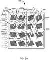
- directional backlight 300 is show with a directional backplane 305 consisting of a plurality of polygonal directional pixels (e.g., directional pixel 310a) arranged in a transparent slab. Each directional pixel is able to scatter a portion of the input planar lightbeams 315 into an output directional lightbeam (e.g., directional lightbeam 320a).
- a directional backplane 305 consisting of a plurality of polygonal directional pixels (e.g., directional pixel 310a) arranged in a transparent slab.
- Each directional pixel is able to scatter a portion of the input planar lightbeams 315 into an output directional lightbeam (e.g., directional lightbeam 320a).
- a set of directional lightbeams (e.g., directional lightbeams 320a-d scattered by directional pixels 310a-d) is modulated by a modulator (e.g., LCD cell 325a to modulate directional lightbeams 320a-d).
- a modulator e.g., LCD cell 325a to modulate directional lightbeams 320a-d.
- LCD cell 325a is used to turn on directional pixels 310a-d while LCD cell 325d is used to turn off directional pixels 330a-d.
- the directional lightbeams scattered by all the directional pixels in the directional backplane 305 and modulated by the LCD cells 325a-d can represent multiple image views that when combined form a 3D image.
- directional backlight 340 is show with a directional backplane 345 consisting of a plurality of circular directional pixels (e.g., directional pixel 350a) arranged in a transparent slab. Each directional pixel is able to scatter a portion of the input planar lightbeams 355 into an output directional lightbeam (e.g., directional lightbeam 360a).
- a set of directional lightbeams e.g., directional lightbeams 360a-d scattered by directional pixels 350a-d
- a modulator e.g., LCD cell 370a to modulate directional lightbeams 360a-d.
- LCD cell 370a is used to turn on directional pixels 350a-d while LCD cell 370d is used to turn off directional pixels 365a-d.
- the directional lightbeams scattered by all the directional pixels in the directional backplane 345 and modulated by modulators such as the LCD cells 370a-d can represent multiple image views that when combined form a 3D image.
- a directional backplane may be designed to have different shapes, such as, for example, a triangular shape (as shown in FIG. 4 ), a hexagonal shape (as shown in FIG. 5 ), or a circular shape (as shown in FIG. 6 ).
- the directional backplane 405 receives input planar lightbeams from three different spatial directions, e.g., input planar lightbeams 410-420.
- This configuration may be used when the input planar lightbeams represent light of different colors, e.g., with input planar lightbeams 410 representing a red color, input planar lightbeams 415 representing a green color, and input planar lightbeams 420 representing a blue color.
- Each of the input planar lightbeams 410-420 is disposed on a side of the triangular directional backplane 405 to focus their light on a set of directional pixels.
- the input planar lightbeams 410 is scattered into directional lightbeams by a set of directional pixels 425-435.
- This subset of directional pixels 425-435 may also receive light from the input planar lightbeams 415-420. However, by design this light is not scattered in the intended view zone of the directional backlight 400.
- planar lightbeams 410 are scattered by a subset G A of directional pixels 425-435 into an intended view zone.
- the intended view zone may be specified by a maximum ray angle ⁇ max measured from a normal to the directional backlight 400.
- Input planar lightbeams 410 may also be scattered by a subset of directional pixels G B 440-450, however those unwanted rays are outside the intended view zone as long as: sin ⁇ max ⁇ ⁇ A + ⁇ B ⁇ A ⁇ ⁇ n eff A ⁇ A 2 + n eff B ⁇ B 2 ⁇ n eff A ⁇ A n eff B ⁇ ⁇
- ⁇ A is the wavelength of input planar lightbeams 410
- n eff A is the effective index of horizontal propagation of input planar lightbeams 410 in the directional backplane 405
- ⁇ B is the wavelength of input planar lightbeams 420 (to be scattered by directional pixels 440-450)
- n eff B is the effective index of horizontal propagation of input planar lightbeams 420 in the directional backplane 405.
- Equation 2 reduces to: sin ⁇ max ⁇ n eff 2
- n refractive index
- Equation 2 reduces to:
- each directional lightbeam may be modulated by a modulator, such as, for example, LCD cell 455. Since precise directional and angular control of directional lightbeams can be achieved with each directional pixel in the directional backplane 405 and the directional lightbeams can be modulated by modulators such as LCD cells, the directional backlight 405 can be designed to generate many different views of 3D images.
- a modulator such as, for example, LCD cell 455. Since precise directional and angular control of directional lightbeams can be achieved with each directional pixel in the directional backplane 405 and the directional lightbeams can be modulated by modulators such as LCD cells, the directional backlight 405 can be designed to generate many different views of 3D images.
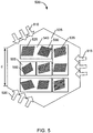
- the directional backplane 405 shown in FIG. 4 may be shaped into a more compact design by realizing that the extremities of the triangular slab can be cut to form a hexagonal shape, as shown in FIG. 5 .
- the directional backplane 505 receives input planar lightbeams from three different spatial directions, e.g., input planar lightbeams 510-520. Each of the input planar lightbeams 510-520 is disposed on alternating sides of the hexagonal directional backplane 505 to focus its light on a subset of directional pixels (e.g., directional pixels 525-535).
- the hexagonal directional backplane 505 has a side length that may range in the order of 10-30 mm, with a directional pixel size in the order of 10-30 ⁇ m.
- directional backlight 500 is shown with multiple configurations of modulators.
- a single modulator may be used to modulate directional lightbeams from a set of directional pixels, e.g., LCD cell 540 for directional pixels 525-535, or a single modulator may be used to modulate a single directional pixel, e.g., LCD cell 555 for directional pixel 560.
- any configuration of modulators for use with directional pixels may be used to modulate directional lightbeams scattered by the directional pixels.
- the directional backlight for use with color input planar lightbeams can have any geometrical shape besides a triangular ( FIG. 4 ) or hexagonal shape ( FIG. 5 ) as long as light from three primary colors is brought from three different directions.
- the directional backlight may be a polygon, a circle, an ellipse, or another shape able to receive light from three different directions. Referring now to FIG. 6 , a directional backlight having a circular shape is described.
- Directional backplane 605 in directional backlight 600 receives input planar lightbeams 610-620 from three different directions.
- Each directional pixel has a circular shape, e.g., directional pixel 620, and scatters a directional lightbeam that is modulated by a modulator, e.g., LCD cell 625.
- a modulator e.g., LCD cell 625.
- Each LCD cell has a rectangular shape and the circular directional backplane 605 is designed to accommodate the rectangular LCD cells for the circular directional pixels (or for polygonal directional pixels if desired).
- FIG. 7 A flowchart for generating a 3D image with a directional backlight in accordance with the present application is illustrated in FIG. 7 .
- the characteristics may include characteristics of the patterned gratings in the directional pixels, such as, for example, a grating length, a grating width, an orientation, a pitch, and a duty cycle.
- each directional pixel in the directional backlight can be specified with a given set of characteristics to generate a directional lightbeam having a direction and an angular spread that is precisely controlled according to the characteristics.
- a directional backplane with directional pixels is fabricated (705).
- the directional backplane is made of a transparent material and may be fabricated with any suitable fabrication technique, such as, for example, optical lithography, nano-imprint lithography, roll-to-roll imprint lithography, direct embossing with an imprint mold, among others.
- the directional pixels may be etched in the directional backplane or be made of patterned gratings with material deposited on top of the directional backplane (e.g., any material that can be deposited and etched or lift-off, including any dielectrics or metal).
- a modulation layer (e.g., an LCD-based modulation layer) is then added to the directional backplane (710).
- the modulation layer includes a plurality of modulators (e.g., LCD cells) that are placed on top of a spacer layer (as shown in FIG. 1 ) above the directional backplane.
- the modulation layer may be designed to have a single modulator for a single directional pixel or a single modulator for a set of directional pixels.
- the directional backplane (and the directional pixels) may have different shapes (e.g., polygon, triangular, hexagonal, circular, etc.) to accommodate the modulation layer made of rectangular shaped modulators.
- the precise control that is achieved with the directional pixels and modulation in the directional backlight enables a 3D image to be generated with an easy to fabricate substantially planar structure.
- Different configurations of directional pixels generate different 3D images.
- the directional lightbeams generated by the directional pixels can be modulated to produce any desired effect in the generated images.
- the directional backlights described herein can be used to provide 3D images in display screens (e.g., in TVs, mobile devices, tablets, video game devices, and so on) as well as in other applications, such as, for example, 3D watches, 3D art devices, 3D medical devices, among others.
Landscapes
- Physics & Mathematics (AREA)
- General Physics & Mathematics (AREA)
- Optics & Photonics (AREA)
- Engineering & Computer Science (AREA)
- Multimedia (AREA)
- Signal Processing (AREA)
- Liquid Crystal (AREA)
- Testing, Inspecting, Measuring Of Stereoscopic Televisions And Televisions (AREA)
- Devices For Indicating Variable Information By Combining Individual Elements (AREA)
Priority Applications (1)
| Application Number | Priority Date | Filing Date | Title |
|---|---|---|---|
| EP17202907.6A EP3301504A1 (en) | 2012-06-01 | 2012-06-01 | Directional backlight with a modulation layer |
Applications Claiming Priority (3)
| Application Number | Priority Date | Filing Date | Title |
|---|---|---|---|
| PCT/US2012/040607 WO2013180737A1 (en) | 2012-06-01 | 2012-06-01 | Directional backlight with a modulation layer |
| EP12877856.0A EP2859402B1 (en) | 2012-06-01 | 2012-06-01 | Directional backlight with a modulation layer |
| EP17202907.6A EP3301504A1 (en) | 2012-06-01 | 2012-06-01 | Directional backlight with a modulation layer |
Related Parent Applications (1)
| Application Number | Title | Priority Date | Filing Date |
|---|---|---|---|
| EP12877856.0A Division EP2859402B1 (en) | 2012-06-01 | 2012-06-01 | Directional backlight with a modulation layer |
Publications (1)
| Publication Number | Publication Date |
|---|---|
| EP3301504A1 true EP3301504A1 (en) | 2018-04-04 |
Family
ID=49673782
Family Applications (2)
| Application Number | Title | Priority Date | Filing Date |
|---|---|---|---|
| EP12877856.0A Active EP2859402B1 (en) | 2012-06-01 | 2012-06-01 | Directional backlight with a modulation layer |
| EP17202907.6A Withdrawn EP3301504A1 (en) | 2012-06-01 | 2012-06-01 | Directional backlight with a modulation layer |
Family Applications Before (1)
| Application Number | Title | Priority Date | Filing Date |
|---|---|---|---|
| EP12877856.0A Active EP2859402B1 (en) | 2012-06-01 | 2012-06-01 | Directional backlight with a modulation layer |
Country Status (9)
| Country | Link |
|---|---|
| EP (2) | EP2859402B1 (zh) |
| JP (1) | JP5964500B2 (zh) |
| KR (1) | KR101788777B1 (zh) |
| CN (1) | CN104335100B (zh) |
| ES (1) | ES2658587T3 (zh) |
| HK (1) | HK1205793A1 (zh) |
| PL (1) | PL2859402T3 (zh) |
| PT (1) | PT2859402T (zh) |
| WO (1) | WO2013180737A1 (zh) |
Cited By (1)
| Publication number | Priority date | Publication date | Assignee | Title |
|---|---|---|---|---|
| EP3638946A4 (en) * | 2017-06-16 | 2020-12-23 | LEIA Inc. | MULTI-VIEW BACKLIGHTING, MULTI-VIEW DISPLAY AND AND METHOD OF USING MULTIPLE BEAMS |
Families Citing this family (80)
| Publication number | Priority date | Publication date | Assignee | Title |
|---|---|---|---|---|
| GB0522968D0 (en) | 2005-11-11 | 2005-12-21 | Popovich Milan M | Holographic illumination device |
| GB0718706D0 (en) | 2007-09-25 | 2007-11-07 | Creative Physics Ltd | Method and apparatus for reducing laser speckle |
| US11726332B2 (en) | 2009-04-27 | 2023-08-15 | Digilens Inc. | Diffractive projection apparatus |
| US9335604B2 (en) | 2013-12-11 | 2016-05-10 | Milan Momcilo Popovich | Holographic waveguide display |
| US11204540B2 (en) | 2009-10-09 | 2021-12-21 | Digilens Inc. | Diffractive waveguide providing a retinal image |
| US9274349B2 (en) | 2011-04-07 | 2016-03-01 | Digilens Inc. | Laser despeckler based on angular diversity |
| WO2016020630A2 (en) | 2014-08-08 | 2016-02-11 | Milan Momcilo Popovich | Waveguide laser illuminator incorporating a despeckler |
| US10670876B2 (en) | 2011-08-24 | 2020-06-02 | Digilens Inc. | Waveguide laser illuminator incorporating a despeckler |
| EP2748670B1 (en) | 2011-08-24 | 2015-11-18 | Rockwell Collins, Inc. | Wearable data display |
| US20150010265A1 (en) | 2012-01-06 | 2015-01-08 | Milan, Momcilo POPOVICH | Contact image sensor using switchable bragg gratings |
| CN103562802B (zh) | 2012-04-25 | 2016-08-17 | 罗克韦尔柯林斯公司 | 全息广角显示器 |
| US9389415B2 (en) | 2012-04-27 | 2016-07-12 | Leia Inc. | Directional pixel for use in a display screen |
| WO2013167864A1 (en) | 2012-05-11 | 2013-11-14 | Milan Momcilo Popovich | Apparatus for eye tracking |
| US9459461B2 (en) | 2012-05-31 | 2016-10-04 | Leia Inc. | Directional backlight |
| US9933684B2 (en) | 2012-11-16 | 2018-04-03 | Rockwell Collins, Inc. | Transparent waveguide display providing upper and lower fields of view having a specific light output aperture configuration |
| WO2014120160A1 (en) * | 2013-01-30 | 2014-08-07 | Hewlett-Packard Development Company, L.P. | Directional grating-based backlighting |
| US9298168B2 (en) | 2013-01-31 | 2016-03-29 | Leia Inc. | Multiview 3D wrist watch |
| WO2014188149A1 (en) | 2013-05-20 | 2014-11-27 | Milan Momcilo Popovich | Holographic waveguide eye tracker |
| ES2704675T3 (es) | 2013-07-30 | 2019-03-19 | Leia Inc | Luz de fondo multi-direccional a base de cuadrícula |
| WO2015015138A1 (en) | 2013-07-31 | 2015-02-05 | Milan Momcilo Popovich | Method and apparatus for contact image sensing |
| CN104159100A (zh) | 2014-07-23 | 2014-11-19 | 京东方科技集团股份有限公司 | 立体显示装置和立体显示方法 |
| US9557466B2 (en) | 2014-07-30 | 2017-01-31 | Leia, Inc | Multibeam diffraction grating-based color backlighting |
| WO2016020632A1 (en) | 2014-08-08 | 2016-02-11 | Milan Momcilo Popovich | Method for holographic mastering and replication |
| US10241330B2 (en) | 2014-09-19 | 2019-03-26 | Digilens, Inc. | Method and apparatus for generating input images for holographic waveguide displays |
| WO2016046514A1 (en) | 2014-09-26 | 2016-03-31 | LOKOVIC, Kimberly, Sun | Holographic waveguide opticaltracker |
| JP6511144B2 (ja) * | 2015-01-10 | 2019-05-15 | レイア、インコーポレイテッドLeia Inc. | 偏光混合(polarization−mixing)ライトガイド、および同ライトガイドを用いるマルチビーム回折格子ベースの背面照明 |
| EP3245444B1 (en) | 2015-01-12 | 2021-09-08 | DigiLens Inc. | Environmentally isolated waveguide display |
| WO2016113533A2 (en) | 2015-01-12 | 2016-07-21 | Milan Momcilo Popovich | Holographic waveguide light field displays |
| WO2016116733A1 (en) | 2015-01-20 | 2016-07-28 | Milan Momcilo Popovich | Holographic waveguide lidar |
| WO2016122679A1 (en) * | 2015-01-28 | 2016-08-04 | Leia Inc. | Three-dimensional (3d) electronic display |
| US9632226B2 (en) | 2015-02-12 | 2017-04-25 | Digilens Inc. | Waveguide grating device |
| US10459145B2 (en) | 2015-03-16 | 2019-10-29 | Digilens Inc. | Waveguide device incorporating a light pipe |
| WO2016148689A1 (en) * | 2015-03-16 | 2016-09-22 | Leia Inc. | Unidirectional grating-based backlighting employing an angularly selective reflective layer |
| WO2016156776A1 (en) | 2015-03-31 | 2016-10-06 | Milan Momcilo Popovich | Method and apparatus for contact image sensing |
| CA2996925C (en) * | 2015-09-05 | 2022-06-28 | Leia Inc. | Light concentrating backlight and near-eye display system using same |
| US10798371B2 (en) * | 2015-09-05 | 2020-10-06 | Leia Inc. | Multiview display with head tracking |
| EP3359999A1 (en) | 2015-10-05 | 2018-08-15 | Popovich, Milan Momcilo | Waveguide display |
| KR102491853B1 (ko) * | 2015-12-09 | 2023-01-26 | 삼성전자주식회사 | 지향성 백라이트 유닛 및 이를 포함한 입체 영상 표시 장치 |
| CH711992A1 (de) * | 2015-12-28 | 2017-06-30 | Regent Beleuchtungskörper Ag | Leuchtkörper und Stehleuchtenanordnung. |
| CN106959510A (zh) * | 2016-01-08 | 2017-07-18 | 京东方科技集团股份有限公司 | 一种显示装置和虚拟现实眼镜 |
| KR102560708B1 (ko) * | 2016-01-15 | 2023-07-27 | 삼성전자주식회사 | 지향성 백라이트 유닛을 구비하는 디스플레이 장치 및 그 조립 방법 |
| KR102274754B1 (ko) * | 2016-01-16 | 2021-07-08 | 레이아 인코포레이티드 | 다중 빔 회절 격자-기반 헤드-업 표시장치 |
| KR102526751B1 (ko) * | 2016-01-25 | 2023-04-27 | 삼성전자주식회사 | 지향성 백라이트 유닛, 3차원 영상 디스플레이 장치, 및 3차원 영상 디스플레이 방법 |
| CA3007627C (en) * | 2016-01-30 | 2021-05-25 | Leia Inc. | Privacy display and dual-mode privacy display system |
| KR102367308B1 (ko) * | 2016-01-30 | 2022-02-24 | 레이아 인코포레이티드 | 수렴 시점들을 갖는 다중 빔 요소-기반 역광 조명 |
| WO2017134412A1 (en) | 2016-02-04 | 2017-08-10 | Milan Momcilo Popovich | Holographic waveguide optical tracker |
| EP3433659A1 (en) | 2016-03-24 | 2019-01-30 | DigiLens, Inc. | Method and apparatus for providing a polarization selective holographic waveguide device |
| EP3433658B1 (en) | 2016-04-11 | 2023-08-09 | DigiLens, Inc. | Holographic waveguide apparatus for structured light projection |
| CN105700226A (zh) * | 2016-04-25 | 2016-06-22 | 京东方科技集团股份有限公司 | 视角控制机构、导光板、背光模组、阵列基板及显示面板 |
| JP6645371B2 (ja) * | 2016-07-15 | 2020-02-14 | オムロン株式会社 | 光デバイス及び立体表示方法 |
| KR102553840B1 (ko) * | 2016-08-31 | 2023-07-10 | 삼성전자주식회사 | 단일 백 라이트 유닛을 포함하는 무안경 3차원 디스플레이 장치 |
| KR102519016B1 (ko) * | 2016-09-07 | 2023-04-05 | 매직 립, 인코포레이티드 | 두꺼운 미디어를 포함하는 가상 현실, 증강 현실 및 혼합 현실 시스템들 및 관련된 방법들 |
| CN106292051B (zh) * | 2016-10-21 | 2017-08-01 | 京东方科技集团股份有限公司 | 一种显示装置及其显示方法 |
| KR102654863B1 (ko) | 2016-11-08 | 2024-04-05 | 삼성전자주식회사 | 지향성 백라이트 유닛 및 이를 포함하는 영상 표시 장치 |
| CN106443867A (zh) * | 2016-11-09 | 2017-02-22 | 苏州苏大维格光电科技股份有限公司 | 一种波导器件及三维显示装置 |
| EP3548939A4 (en) | 2016-12-02 | 2020-11-25 | DigiLens Inc. | UNIFORM OUTPUT LIGHTING WAVEGUIDE DEVICE |
| WO2018125574A1 (en) | 2016-12-31 | 2018-07-05 | Vuzix Corporation | Imaging light guide with expanded light distribution |
| FR3061461B1 (fr) * | 2017-01-03 | 2020-06-19 | Valeo Vision | Systeme d'avertissement lumineux pour vehicule automobile et procede d'avertissement lumineux |
| US10545346B2 (en) | 2017-01-05 | 2020-01-28 | Digilens Inc. | Wearable heads up displays |
| JP6618641B2 (ja) | 2017-01-16 | 2019-12-11 | 三菱電機株式会社 | 質感表示装置、質感表示方法、及び質感表示プログラム |
| US10416468B2 (en) | 2017-03-28 | 2019-09-17 | The Charles Stark Draper Laboratory, Inc. | Light field generator devices with series output couplers |
| CA3145713A1 (en) * | 2017-04-08 | 2018-10-11 | Leia Inc. | Multiview backlight, mode-switchable backlight, and 2d/3d mode-switchable display |
| EP3598203B1 (en) * | 2017-04-28 | 2021-09-15 | Cloudminds (Shenzhen) Robotics Systems Co., Ltd. | Directional optical waveguide, directional backlight module and display device |
| WO2018213101A1 (en) * | 2017-05-14 | 2018-11-22 | Leia Inc. | Multiview backlight, display, and method employing active emitters |
| EP3635456A4 (en) | 2017-06-13 | 2021-01-13 | Vuzix Corporation | IMAGE LIGHT GUIDE WITH OVERLAPPING GRIDS WITH EXTENDED LIGHT DISTRIBUTION |
| US10747176B2 (en) | 2017-09-04 | 2020-08-18 | Electronics And Telecommunications Research Institute | System and method for 3D holographic display using spatial-division multiplexed diffractive optical elements for viewing zone improvement |
| US10942430B2 (en) | 2017-10-16 | 2021-03-09 | Digilens Inc. | Systems and methods for multiplying the image resolution of a pixelated display |
| CN107741666B (zh) | 2017-10-27 | 2020-08-04 | 上海天马微电子有限公司 | 一种显示装置 |
| WO2019136476A1 (en) | 2018-01-08 | 2019-07-11 | Digilens, Inc. | Waveguide architectures and related methods of manufacturing |
| CN115356905A (zh) | 2018-01-08 | 2022-11-18 | 迪吉伦斯公司 | 波导单元格中全息光栅高吞吐量记录的系统和方法 |
| EP3765897B1 (en) | 2018-03-16 | 2024-01-17 | Digilens Inc. | Holographic waveguides incorporating birefringence control and methods for their fabrication |
| US10345506B1 (en) * | 2018-07-16 | 2019-07-09 | Shenzhen Guangjian Technology Co., Ltd. | Light projecting method and device |
| US11402801B2 (en) | 2018-07-25 | 2022-08-02 | Digilens Inc. | Systems and methods for fabricating a multilayer optical structure |
| CN110908134B (zh) * | 2018-08-28 | 2021-01-26 | 京东方科技集团股份有限公司 | 一种显示装置及显示系统 |
| EP3874199A4 (en) * | 2018-10-31 | 2022-07-13 | LEIA Inc. | MULTIPLE VIEW BACKILLUMINATION, DISPLAY UNIT, AND METHOD INCLUDING OPTICAL MASK ELEMENTS |
| KR20210138609A (ko) | 2019-02-15 | 2021-11-19 | 디지렌즈 인코포레이티드. | 일체형 격자를 이용하여 홀로그래픽 도파관 디스플레이를 제공하기 위한 방법 및 장치 |
| KR20210134763A (ko) | 2019-03-12 | 2021-11-10 | 디지렌즈 인코포레이티드. | 홀로그래픽 도파관 백라이트 및 관련된 제조 방법 |
| CN114207492A (zh) | 2019-06-07 | 2022-03-18 | 迪吉伦斯公司 | 带透射光栅和反射光栅的波导及其生产方法 |
| KR20220038452A (ko) | 2019-07-29 | 2022-03-28 | 디지렌즈 인코포레이티드. | 픽셀화된 디스플레이의 이미지 해상도와 시야를 증배하는 방법 및 장치 |
| KR20220054386A (ko) | 2019-08-29 | 2022-05-02 | 디지렌즈 인코포레이티드. | 진공 브래그 격자 및 이의 제조 방법 |
Citations (4)
| Publication number | Priority date | Publication date | Assignee | Title |
|---|---|---|---|---|
| US6580529B1 (en) * | 1998-04-02 | 2003-06-17 | Elop Electro -Optics Industries Ltd. | Holographic optical devices |
| US7114820B1 (en) * | 1998-12-30 | 2006-10-03 | Nokia Mobile Phones, Ltd. | Backlighting light pipe for illuminating a flat-panel display |
| US20090244706A1 (en) * | 2005-10-13 | 2009-10-01 | Tapani Levola | Illumination Method for Displaying Different Graphical Layouts |
| US20100207964A1 (en) * | 2007-06-14 | 2010-08-19 | Jyrki Kimmel | Displays with integrated backlighting |
Family Cites Families (13)
| Publication number | Priority date | Publication date | Assignee | Title |
|---|---|---|---|---|
| US6919950B2 (en) * | 2000-08-29 | 2005-07-19 | Roman S. Dabrowski | Liquid crystal device and a liquid crystal material |
| JP2004077897A (ja) * | 2002-08-20 | 2004-03-11 | Nippon Telegr & Teleph Corp <Ntt> | 表示装置 |
| EP1666992A1 (fr) * | 2004-12-02 | 2006-06-07 | Asulab S.A. | Pièce d'horlogerie comprenant un décor lumineux |
| EP1666933A1 (fr) * | 2004-12-02 | 2006-06-07 | Asulab S.A. | Dispositif optique a double fonction d'illumination et de formation d'une image figurative |
| US7714368B2 (en) | 2006-06-26 | 2010-05-11 | Aptina Imaging Corporation | Method and apparatus providing imager pixel array with grating structure and imager device containing the same |
| CN101501391B (zh) | 2006-07-03 | 2011-10-12 | 诺基亚公司 | 在包括用户界面照明的装置中改变图形 |
| JP5157115B2 (ja) * | 2006-09-28 | 2013-03-06 | 凸版印刷株式会社 | 回折格子から成る表示体およびそれを応用した印刷物 |
| US20080204873A1 (en) * | 2007-02-23 | 2008-08-28 | Strategic Patent Acquisitions Llc | Techniques for three dimensional displays |
| US7507012B2 (en) * | 2007-05-16 | 2009-03-24 | Rohm And Haas Denmark Finance A/S | LCD displays with light redirection |
| TWI387316B (zh) * | 2008-11-18 | 2013-02-21 | Ind Tech Res Inst | 立體影像顯示裝置與立體影像顯示方法 |
| JP2010237416A (ja) | 2009-03-31 | 2010-10-21 | Sharp Corp | 立体表示装置 |
| JP5493978B2 (ja) * | 2010-02-19 | 2014-05-14 | 凸版印刷株式会社 | 画像表示体及び情報媒体 |
| JP2011133677A (ja) * | 2009-12-24 | 2011-07-07 | Toppan Printing Co Ltd | ブランク媒体、画像表示体及び情報媒体 |
-
2012
- 2012-06-01 KR KR1020147027174A patent/KR101788777B1/ko active IP Right Grant
- 2012-06-01 JP JP2015514974A patent/JP5964500B2/ja active Active
- 2012-06-01 EP EP12877856.0A patent/EP2859402B1/en active Active
- 2012-06-01 ES ES12877856.0T patent/ES2658587T3/es active Active
- 2012-06-01 WO PCT/US2012/040607 patent/WO2013180737A1/en active Application Filing
- 2012-06-01 EP EP17202907.6A patent/EP3301504A1/en not_active Withdrawn
- 2012-06-01 CN CN201280072700.0A patent/CN104335100B/zh active Active
- 2012-06-01 PL PL12877856T patent/PL2859402T3/pl unknown
- 2012-06-01 PT PT128778560T patent/PT2859402T/pt unknown
-
2015
- 2015-07-06 HK HK15106381.7A patent/HK1205793A1/zh unknown
Patent Citations (4)
| Publication number | Priority date | Publication date | Assignee | Title |
|---|---|---|---|---|
| US6580529B1 (en) * | 1998-04-02 | 2003-06-17 | Elop Electro -Optics Industries Ltd. | Holographic optical devices |
| US7114820B1 (en) * | 1998-12-30 | 2006-10-03 | Nokia Mobile Phones, Ltd. | Backlighting light pipe for illuminating a flat-panel display |
| US20090244706A1 (en) * | 2005-10-13 | 2009-10-01 | Tapani Levola | Illumination Method for Displaying Different Graphical Layouts |
| US20100207964A1 (en) * | 2007-06-14 | 2010-08-19 | Jyrki Kimmel | Displays with integrated backlighting |
Cited By (1)
| Publication number | Priority date | Publication date | Assignee | Title |
|---|---|---|---|---|
| EP3638946A4 (en) * | 2017-06-16 | 2020-12-23 | LEIA Inc. | MULTI-VIEW BACKLIGHTING, MULTI-VIEW DISPLAY AND AND METHOD OF USING MULTIPLE BEAMS |
Also Published As
| Publication number | Publication date |
|---|---|
| PL2859402T3 (pl) | 2018-08-31 |
| KR101788777B1 (ko) | 2017-10-20 |
| CN104335100A (zh) | 2015-02-04 |
| EP2859402A4 (en) | 2016-04-13 |
| EP2859402B1 (en) | 2017-11-22 |
| ES2658587T3 (es) | 2018-03-12 |
| HK1205793A1 (zh) | 2015-12-24 |
| EP2859402A1 (en) | 2015-04-15 |
| PT2859402T (pt) | 2018-02-08 |
| JP5964500B2 (ja) | 2016-08-03 |
| WO2013180737A1 (en) | 2013-12-05 |
| KR20150021017A (ko) | 2015-02-27 |
| CN104335100B (zh) | 2017-06-13 |
| JP2015530604A (ja) | 2015-10-15 |
Similar Documents
| Publication | Publication Date | Title |
|---|---|---|
| EP2859402B1 (en) | Directional backlight with a modulation layer | |
| US10082613B2 (en) | Directional backlight with a modulation layer | |
| US10120198B2 (en) | Directional backlight | |
| US9785119B2 (en) | Multiview display screen and multiview mobile device using same | |
| EP2856244B1 (en) | Directional backlight | |
| TWI728289B (zh) | 可切換模式的背光板、顯示器及方法 | |
| EP2951649B1 (en) | Multiview 3d wrist watch | |
| US11194086B2 (en) | Three-dimensional (3D) electronic display | |
| WO2014081415A1 (en) | Directional waveguide-based pixel for use in a multiview display screen | |
| WO2014051623A1 (en) | Directional waveguide-based backlight for use in a multivew display screen | |
| US20140300947A1 (en) | Directional pixel for use in a display screen | |
| EP4001994A1 (en) | Directional pixel for use in a display screen | |
| CN107278274B (zh) | 一种指向性光波导、指向性背光模组及显示装置 | |
| CN113614446A (zh) | 双视区背光、双模式显示器以及采用定向发射器的方法 | |
| WO2017118048A1 (zh) | 显示装置及其驱动方法 | |
| WO2014051624A1 (en) | Directional waveguide-based backlight with integrated hybrid lasers for use in a multivew display screen | |
| TW202024747A (zh) | 具有光罩元件的多視域背光件、顯示器和方法 | |
| CN118011647A (zh) | 一种空间光调制组件、全息显示系统和电子设备 |
Legal Events
| Date | Code | Title | Description |
|---|---|---|---|
| PUAI | Public reference made under article 153(3) epc to a published international application that has entered the european phase |
Free format text: ORIGINAL CODE: 0009012 |
|
| AC | Divisional application: reference to earlier application |
Ref document number: 2859402 Country of ref document: EP Kind code of ref document: P |
|
| AK | Designated contracting states |
Kind code of ref document: A1 Designated state(s): AL AT BE BG CH CY CZ DE DK EE ES FI FR GB GR HR HU IE IS IT LI LT LU LV MC MK MT NL NO PL PT RO RS SE SI SK SM TR |
|
| STAA | Information on the status of an ep patent application or granted ep patent |
Free format text: STATUS: THE APPLICATION IS DEEMED TO BE WITHDRAWN |
|
| 18D | Application deemed to be withdrawn |
Effective date: 20181005 |