EP3301467B1 - Tempérage amélioré d'un rotor rmn mas - Google Patents
Tempérage amélioré d'un rotor rmn mas Download PDFInfo
- Publication number
- EP3301467B1 EP3301467B1 EP17189426.4A EP17189426A EP3301467B1 EP 3301467 B1 EP3301467 B1 EP 3301467B1 EP 17189426 A EP17189426 A EP 17189426A EP 3301467 B1 EP3301467 B1 EP 3301467B1
- Authority
- EP
- European Patent Office
- Prior art keywords
- mas
- temperature control
- rotor
- nmr
- nozzle
- Prior art date
- Legal status (The legal status is an assumption and is not a legal conclusion. Google has not performed a legal analysis and makes no representation as to the accuracy of the status listed.)
- Active
Links
Images



Classifications
-
- G—PHYSICS
- G01—MEASURING; TESTING
- G01R—MEASURING ELECTRIC VARIABLES; MEASURING MAGNETIC VARIABLES
- G01R33/00—Arrangements or instruments for measuring magnetic variables
- G01R33/20—Arrangements or instruments for measuring magnetic variables involving magnetic resonance
- G01R33/28—Details of apparatus provided for in groups G01R33/44 - G01R33/64
- G01R33/30—Sample handling arrangements, e.g. sample cells, spinning mechanisms
- G01R33/31—Temperature control thereof
-
- G—PHYSICS
- G01—MEASURING; TESTING
- G01R—MEASURING ELECTRIC VARIABLES; MEASURING MAGNETIC VARIABLES
- G01R33/00—Arrangements or instruments for measuring magnetic variables
- G01R33/20—Arrangements or instruments for measuring magnetic variables involving magnetic resonance
- G01R33/28—Details of apparatus provided for in groups G01R33/44 - G01R33/64
- G01R33/30—Sample handling arrangements, e.g. sample cells, spinning mechanisms
- G01R33/307—Sample handling arrangements, e.g. sample cells, spinning mechanisms specially adapted for moving the sample relative to the MR system, e.g. spinning mechanisms, flow cells or means for positioning the sample inside a spectrometer
Definitions
- the invention relates to a method for operating an NMR probe head with an MAS stator for receiving an essentially circular cylindrical hollow MAS rotor with an outer jacket with an outer diameter D and a sample substance in a sample volume, the MAS rotor in a measuring position within the MAS -Stator is pressurized by means of a device for gas supply with a bearing nozzle and is set in rotation around the cylinder axis of the MAS rotor with a rotation frequency f ⁇ 30kHz by means of a pneumatic drive, with a temperature control gas under a temperature control nozzle during the NMR-MAS measurement is blown onto the outer jacket of the MAS rotor at an angle ⁇ ⁇ 90 ° with respect to the longitudinal axis of the cylindrically symmetrical MAS rotor.
- the present invention relates generally to the field of magnetic resonance (MR).
- MR magnetic resonance
- NMR nuclear magnetic resonance
- spectroscopy is a commercially widespread MR method for characterizing the chemical composition of substances.
- MAS Magic Angle Spinning
- the sample is filled into a MAS rotor.
- MAS rotors are cylindrical tubes that are closed with one or two caps, the upper one with wing elements ("paddle wheels”).
- the MAS rotor is arranged in a MAS stator, and the MAS rotor is driven for rotation via the vane elements with gas pressure.
- the combination of the MAS rotor and MAS stator is called the MAS turbine.
- the MAS turbine is arranged in an NMR MAS probe head.
- the probe head has a cylindrical shielding tube.
- HF electronic components, in particular HF coils, and the MAS turbine are housed therein.
- the probe head with its shielding tube is typically inserted from below into the vertical room temperature bore of a superconducting magnet, positioned and held in place with hooks, supports, screws or the like.
- the MAS turbine is then located exactly in the magnetic center of the magnet.
- the rotor is usually tempered by so-called VT channels or nozzles, which are directed approximately towards the center of the rotor.
- tempered gas is either injected into the radial bearings, optionally branched off from there (so-called VTN design) or supplied via a separate channel, the bearings then being operated at a temperature independent of VT, for example room temperature (so-called DVT design).
- VTN and DVT solutions An essential feature of the VTN and DVT solutions is the design of the temperature control nozzles: Due to the positioning and / or the size of the temperature control nozzles, they introduce the gas in such a way that the gas speed directly on the rotor is significantly lower than the speed of rotation of the rotor, so that the The cooling effort is very high in order to temper the sample even slightly below room temperature (see the comparison table below).
- a further disadvantage is that in all cases a temperature gradient occurs over the length of the rotor, which is undesirable; ie in the middle of the rotor there is a heating up to approx. 55 ° C with a total length of only 6mm (see the figure "simulation report" in the drawing).
- the present invention is based on the object of providing a method of the type defined at the outset and a corresponding MAS stator for an NMR-MAS probe head with which a considerably better temperature control is achieved even with very rapidly rotating MAS rotors.
- This object is achieved by a method with the features defined at the beginning, which is characterized in that the flow speed of the temperature control gas blown through the temperature control nozzle onto the MAS rotor in the nozzle cross section is at least half the circumferential speed of the outer jacket of the rotating MAS rotor and at most Corresponds to the speed of sound in the temperature control gas, and that the temperature control nozzle has an internal diameter d between 0.04 mm and 0.5 mm and is subjected to a pressure of 0.1 MPa to 0.5 MPa.
- the present invention also provides a correspondingly designed and dimensioned MAS stator for NMR-MAS spectroscopy, which allows a significantly better temperature control of the MAS rotor even at higher rotation frequencies.
- the present invention attempts to blow in the compressed air for cooling the MAS rotor at a certain minimum speed in order to effect a significant exchange of the air layers on the rotor surface and thereby improved cooling.
- the velocity of the gas flow in the VT Nozzle should be at least 50% of the speed of rotation of the rotor.
- the upper limit is the speed of sound, which is also the upper limit of the rotational speed of the rotor.
- Another advantage of the present invention is that the existing, commercially available MAS stator hardly needs to be modified and the additional parts only require very little material expenditure, so that the teaching according to the invention can be implemented extremely inexpensively.
- Particularly preferred variants of the invention are characterized in that the outer casing of the MAS rotor has an outer diameter D 1.9 mm, and that the MAS rotor is rotated with a rotation frequency f 50 kHz, preferably with f 67 kHz.
- a rotation frequency f 50 kHz preferably with f 67 kHz.
- the standard volume flow of the temperature control gas blown through a temperature control nozzle is between 0.01 l / min and 10 l / min. If the gas flow is too low, the temperature is inadequate, while a flow that is too high can have a negative effect on the rotation and may therefore also be uneconomical.
- the scope of the present invention also includes an NMR-MAS probe head with a MAS stator of the type according to the invention described above, in which the outer jacket of the MAS rotor has an outer diameter D 1.9 mm, in particular 0.7 mm D 1.3 mm , wherein the MAS rotor is rotated with a rotation frequency f ⁇ 67kHz.
- the prior art discloses, for example, according to the one cited at the beginning US 7,915,893 B2 Outside diameter D of the rotor of about 3mm and regular rotation frequencies f of about 30kHz.
- stator variants Two fundamentally different stator variants can be used here, namely on the one hand a room temperature variant in which the stator is open and the temperature control current can escape into the environment, and on the other hand a closed cryogenic variant with cooled transmitter / receiver electronics, in which the rotor is operated in a closed tube so that the temperature control currents do not reach the cryo-electronics.
- the MAS stator is constructed to be open so that the temperature gas flow can escape into the environment after it has come into contact with the outer jacket of the MAS rotor.
- the temperature control nozzle is arranged such that a temperature control gas stream can be blown onto the outer jacket of the MAS rotor at an angle ⁇ ⁇ 45 °, preferably ⁇ ⁇ 30 °, relative to the longitudinal axis of the cylindrically symmetrical MAS rotor.
- the temperature control nozzle does not normally attach exactly to the rotor surface, the irradiation of the temperature control gas should aim at the rotor at an angle.
- such an inclined temperature control flow reaches the gap between the rotor and an RF coil surrounding it better and more effectively. Therefore, starting from the radial bearing, the nozzles preferably aim obliquely into this gap. This makes it possible to dissipate the frictional heat from the rotor surface more efficiently.
- the gas flow is directed downwards, specifically at an angle of attack of 0 ° to 80 °, preferably between 20 ° and 40 °.
- Another advantage of the nozzle angle in contrast to conventional impact nozzles is that the rotor experiences a downward force, which gives it stability, which is particularly important for small rotors (i.e. with an outer diameter D ⁇ 1.9mm).
- the MAS stator has a closed construction, so that the tempering gas stream cannot escape directly into the environment after it has come into contact with the outer jacket of the MAS rotor.
- the temperature control nozzle is then arranged such that the angle ⁇ relative to the longitudinal axis of the cylindrically symmetrical MAS rotor is ⁇ 10 °.
- a gas flow can also be conducted parallel to the rotor.
- a central pipe allows the temperature gas to be routed in a more controlled manner.
- thermocontrol nozzle is arranged such that a temperature control gas stream can be blown along the outer jacket of the MAS rotor at an angle ⁇ ⁇ 0 °, i.e. parallel to the longitudinal axis of the cylinder-symmetrical MAS rotor.
- angle ⁇ ⁇ 0 ° i.e. parallel to the longitudinal axis of the cylinder-symmetrical MAS rotor.
- the MAS rotor is surrounded by a solenoid-shaped RF coil, which is either designed to be cantilevered or wound on the outer surface of a tube and arranged in such a way that the temperature gas flow is guided between the rotor and the tube or the coil can be.
- the RF coil is a necessary component for NMR measurements. Together with a carrier tube, it also ensures that the temperature control gas is routed here.
- the MAS rotor is surrounded by the solenoid-shaped RF coil at a distance between 0.02 mm and 0.3 mm from the inner wall of the support tube.
- the gap width can be adjusted in such a way that the temperature control of the MAS rotor is improved.
- Embodiments of the inventive NMR-MAS probe head are also advantageous, which are distinguished by the fact that there are several temperature control nozzles, in particular identical to one another, which are preferably arranged symmetrically around the longitudinal axis of the cylindrically symmetrical MAS rotor. Such a radial symmetry avoids mechanical influencing of the rotor in a certain direction. In addition, a large number of nozzles enables a higher temperature gas flow.
- Embodiments of the invention are also particularly preferred NMR-MAS probe head in which the temperature control nozzle (s) is (are) installed in a radial bearing of the MAS stator. This gives a very compact structure.
- the MAS system simplifies the simultaneous loading of the store and the temperature control through a uniform gas supply.
- the temperature control nozzle (s) can be charged with temperature control gas via a separate channel.
- embodiments of the probe head according to the invention in which the MAS rotor is made of sapphire, tetragonally stabilized zirconium oxide and / or silicon nitride, with a wall thickness between 0.2 mm and 0.7 mm, preferably about 0.3 mm and 0.55 mm, prove to be particularly useful , and with a diameter of less than 4mm, in particular about 3.2mm, about 1.9mm or about 1.3mm.
- These materials are particularly suitable for MAS-NMR because they are non-magnetic, electrically non-conductive, have sufficient mechanical strength to withstand the forces occurring during rotation and their wall thickness can be adjusted in the above-mentioned manner for maximum transmission.
- the invention in its physical form relates to a novel embodiment of an MAS stator and an NMR-MAS probe head with this MAS stator for carrying out the above-described method according to the invention and is mainly used as a component of a magnetic resonance apparatus.
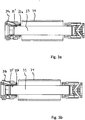
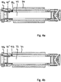
- All embodiments of the arrangement according to the invention each include a MAS stator 11; 21; 31a; 31b; 41a; 41b of an NMR probe head 10; 20 for receiving an essentially circular cylindrical hollow MAS rotor 13; 23; 33; 43 with an outer jacket with an outer diameter D, which contains a sample substance in a sample volume and is in a measuring position within the MAS stator 11; 21; 31a; 31b; 41a; 41b by means of a device for gas supply with at least one bearing nozzle 12 '; 22 '; 32 '; 42 ' mounted on pressurized gas and by means of a pneumatic drive in a rotation with a rotation frequency f about the cylinder axis of the MAS rotor 13; 23; 33; 43 can be moved.
- the MAS rotor 13; 23; 33; 43 is each of a solenoid-shaped RF coil 14; 24; 34; 44 surrounded.
- all embodiments of the invention (as well as arrangements according to the prior art) have one or more temperature control nozzle (s) 12; 32a; 32b; 42a; 42b , through which, during an NMR-MAS measurement, a temperature control gas is applied to the outer jacket of the MAS rotor 13; 33; 43 is blown.
- the invention is characterized in that the flow rate of the through the temperature control nozzle 12; 32a; 32b; 42a; 42b on the MAS rotor 13; 33; 43 blown temperature gas in the nozzle cross-section at least half the circumferential speed of the outer jacket of the rotating MAS rotor 13; 33; 43 and corresponds at most to the speed of sound in the temperature control gas.
- a temperature-controlled gas stream is usually directed perpendicularly onto the rotor by means of larger nozzles. This means that only a small amount of heat can be exchanged on the rotor, so that a thermal gradient is formed towards the center of the rotor.
- the air flow is, however, preferably blown in between the coil and the rotor by means of an angled nozzle and at a sufficiently high speed.
- the temperature control flow is connected to the bearing nozzles, and the temperature control nozzle has a smaller diameter than the bearing nozzle, so that high flow velocities can be achieved.
- the main flow in the gap between rotor and coil also runs there and ensures efficient cooling.
- the HF coil is usually wound on a tube so that the axial temperature control current is guided along the rotor. Guiding the VT flow together with a defined gap between the rotor and the central tube can bring about a further VT optimization. Central tube variants are also conceivable.
- the MAS rotor-stator system according to the invention is designed for rotor sizes with outside diameters D 1.9 mm. Especially with these smaller rotors, the frictional heat is quite large and the temperature of the system is difficult to control. This is probably also due to the lower mass and the smaller surface area of the smaller rotors in relation to the resulting friction.
- R s is the specific gas constant of the gas in question.
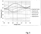
- Fig. 5 the solid line denotes the state of the art (as currently offered by Bruker BioSpin GmbH), the dashed lines denote the invention with different nozzles.
- This comparative graphic shows that the temperature control nozzles reduce the maximum temperature and, in some cases, the temperature gradient on the rotor. It also shows that not only the air speed has an influence on the rotor temperature, but also the flow rate. The larger the temperature control nozzle, the stronger the cooling effect on the rotor.
- Fig. 6 finally illustrates the course of the temperature at a point on the rotor as a function of the gap between the rotor and the central tube.
- This graphic shows that the temperature is on the rotor surface assume a large gap initially increases when the gap is reduced. A maximum is reached at a gap of about 0.35 mm. If the gap is reduced further, the cooling performance improves up to an optimum of approx. 0.06 mm, below which the temperature rises sharply again. For this, however, it must be taken into account that a smaller gap requires a higher pressure, so that the optimum in terms of equipment may not be 0.06mm, but rather 0.1mm.
Landscapes
- Physics & Mathematics (AREA)
- Condensed Matter Physics & Semiconductors (AREA)
- General Physics & Mathematics (AREA)
- Heat Treatment Of Articles (AREA)
- Measuring Temperature Or Quantity Of Heat (AREA)
- General Induction Heating (AREA)
- Testing Of Devices, Machine Parts, Or Other Structures Thereof (AREA)
- Turbine Rotor Nozzle Sealing (AREA)
- Crystals, And After-Treatments Of Crystals (AREA)
Claims (15)
- Procédé d'actionnement d'une tête de sonde RMN (10; 20) équipée d'un stator RAM (11 ; 21 ; 31a ; 31b ; 41a ; 41b) conçu pour recevoir un rotor RAM (13 ; 23 ; 33 ; 43) creux, substantiellement cylindrique circulaire, présentant une enveloppe extérieure de diamètre extérieur D et une substance d'échantillonnage dans un volume d'échantillonnage, ledit rotor RAM (13 ; 23 ; 33 ; 43) étant supporté par du gaz sous pression en un emplacement de mesure, à l'intérieur dudit stator RAM (11 ; 21 ; 31a ; 31b ; 41a ; 41b), au moyen d'un dispositif d'arrivée de gaz doté d'un injecteur de palier (12' ; 22' ; 32' ; 42'), et étant animé d'une rotation autour de l'axe cylindrique dudit rotor RAM (13 ; 23 ; 33 ; 43) au moyen d'un entraînement pneumatique, avec une fréquence de rotation f ≥ 30 kHz, sachant que, durant la mesure RMN-RAM, un gaz d'équilibrage thermique est insufflé sur l'enveloppe extérieure du rotor RAM (13 ; 23 ; 33 ; 43) au moyen d'une buse (12 ; 32a ; 32b ; 42a ; 42b) d'équilibrage de température, selon un angle α < 90° par rapport à l'axe longitudinal dudit rotor RAM (13 ; 23 ; 33 ; 43) à symétrie cylindrique,
caractérisé par le faitque la vitesse d'écoulement du gaz d'équilibrage thermique insufflé sur le rotor RAM (13 ; 33 ; 43) par l'intermédiaire de la buse (12 ; 32a ; 32b ; 42a ; 42b) d'équilibrage de température correspond, dans la section transversale de ladite buse, au minimum à la moitié de la vitesse périphérique de l'enveloppe extérieure dudit rotor RAM (13 ; 33 ; 43) effectuant une rotation et, au maximum, à la vitesse du son dans ledit gaz d'équilibrage thermique ;et par le fait que ladite buse (12 ; 32a ; 32b ; 42a ; 42b) d'équilibrage de température présente un diamètre intérieur d compris entre 0,04 mm et 0,5 mm, et est sollicitée par une pression de 0,1 MPa à 0,5 MPa. - Procédé selon la revendication 1, caractérisé par le fait que l'enveloppe extérieure du rotor RAM (13 ; 33 ; 43) présente un diamètre extérieur D ≤ 1,9 mm ; et par le fait que ledit rotor RAM (13 ; 33 ; 43) est animé d'une rotation à une fréquence f ≥ 50 kHz, de préférence f ≥ 67 kHz.
- Procédé selon la revendication 1 ou 2, caractérisé par le fait que le débit volumique standard du gaz d'équilibrage thermique, insufflé par l'intermédiaire d'une buse (12 ; 32a ; 32b ; 42a ; 42b) d'équilibrage de température, se situe entre 0,01 L/min et 10 L/min.
- Stator RAM (11 ; 31a; 31b ; 41a; 41b) dévolu à la mise en œuvre du procédé conforme à l'une des revendications précédentes, muni d'un dispositif de régulation thermique incluant au moins une buse (12 ; 32a ; 32b ; 42a ; 42b) d'équilibrage de température, dédiée à l'équilibrage thermique du rotor RAM (13 ; 33 ; 43), ainsi que des moyens affectés à la sollicitation de ladite buse (12 ; 32a ; 32b ; 42a ; 42b) d'équilibrage de température par une pression, caractérisé par le fait que la buse (12 ; 32a ; 32b ; 42a ; 42b) d'équilibrage de température, à présence minimale, est pourvue d'un diamètre intérieur d compris entre 0,04 mm et 0,5 mm ; et par le fait que lesdits moyens, affectés à la sollicitation de ladite buse (12 ; 32a ; 32b ; 42a ; 42b) d'équilibrage de température par une pression, sont conçus pour solliciter ladite buse (12 ; 32a ; 32b ; 42a ; 42b) d'équilibrage de température par une pression de 0,1MPa à 0,5 MPa (= 1 bar à 5 bar).
- Tête de sonde RMN-RAM (10) dotée d'un stator RAM (11 ; 31a ; 31b ; 41a ; 41b) conforme à la revendication 4, caractérisée par le fait que l'enveloppe extérieure du rotor RAM (13 ; 33 ; 43) présente un diamètre extérieur D ≤ 1,9 mm, notamment 0,7 mm ≤ D ≤ 1,3 mm ; et par le fait que ladite tête de sonde RMN-RAM (10) inclut des moyens conçus pour imprimer, audit rotor RAM (13 ; 33 ; 43), une rotation à une fréquence f ≥ 67 kHz.
- Tête de sonde RMN-RAM selon la revendication 5, caractérisée par le fait que le stator RAM (11 ; 31a ; 31b) présente un agencement structurel ouvert, de telle sorte que le flux de gaz d'équilibrage thermique puisse s'échapper vers l'espace environnant après son contact avec l'enveloppe extérieure du rotor RAM (13 ; 33) ; et par le fait que la buse (12 ; 32a ; 32b) d'équilibrage de température est disposée de façon telle qu'un flux de gaz d'équilibrage thermique puisse être insufflé sur ladite enveloppe extérieure du rotor RAM (13 ; 33) selon un angle α ≤ 45°, de préférence α ≤ 30°, par rapport à l'axe longitudinal dudit rotor RAM (13 ; 33) à symétrie cylindrique.
- Tête de sonde RMN-RAM selon la revendication 5, caractérisée par le fait que le stator RAM (41a ; 41b) présente un agencement structurel fermé, de telle manière que le flux de gaz d'équilibrage thermique ne puisse pas s'échapper directement vers l'espace environnant après son contact avec l'enveloppe extérieure du rotor RAM (43) ; et par le fait que la buse (42a ; 42b) d'équilibrage de température est disposée de telle sorte que l'angle α, par rapport à l'axe longitudinal dudit rotor RAM (43) à symétrie cylindrique, soit α ≤ 10°.
- Tête de sonde RMN-RAM selon la revendication 7, caractérisée par le fait qu'un interstice présentant une largeur b comprise entre 0,02 mm et 0,3 mm demeure libre, pour le flux de gaz d'équilibrage thermique, entre l'enveloppe extérieure du rotor RAM (43) et la surface intérieure du stator RAM (41a ; 41b) qui entoure ledit rotor.
- Tête de sonde RMN-RAM selon la revendication 7 ou 8, caractérisée par le fait que la buse (42b) d'équilibrage de température est disposée de façon telle qu'un flux de gaz d'équilibrage thermique puisse être insufflé le long de l'enveloppe extérieure du rotor RAM (43) selon un angle α ~ 0°, c'est-à-dire parallèlement à l'axe longitudinal dudit rotor RAM (43) à symétrie cylindrique.
- Tête de sonde RMN-RAM selon l'une des revendications 5 à 9, caractérisée par le fait que le rotor RAM (13 ; 33 ; 43) est entouré par une bobine HF (14 ; 34 ; 44) en forme de solénoïde, qui est enroulée sur la surface extérieure d'un tube et est disposée de telle manière que le flux de gaz d'équilibrage thermique puisse être guidé entre ledit rotor et ledit tube.
- Tête de sonde RMN-RAM selon la revendication 10, caractérisée par le fait que le rotor RAM (13 ; 33 ; 43) est entouré, à l'aide de la bobine HF (14 ; 34 ; 44) en forme de solénoïde, à une distance comprise entre 0,02 mm et 0,3 mm par rapport à la paroi intérieure du tube.
- Tête de sonde RMN-RAM selon l'une des revendications 5 à 11, caractérisée par la présence de plusieurs buses (12 ; 32a ; 32b ; 42a ; 42b) d'équilibrage de température offrant, en particulier, des agencements structurels identiques entre eux et disposées, de préférence, symétriquement autour de l'axe longitudinal du rotor RAM (13 ; 33 ; 43) à symétrie cylindrique.
- Tête de sonde RMN-RAM selon l'une des revendications 5 à 12, caractérisée par le fait que la (les) buse(s) (12 ; 32a ; 32b ; 42a ; 42b) d'équilibrage de température est (sont) intégrée(s) dans un palier radial du stator RAM (11 ; 31a; 31b ; 41a; 41b).
- Tête de sonde RMN-RAM selon l'une des revendications 5 à 11, caractérisée par le fait que la (les) buse(s) (32a ; 32b) d'équilibrage de température peu(ven)t être alimentée(s) en gaz d'équilibrage thermique par l'intermédiaire d'un canal distinct.
- Tête de sonde RMN-RAM selon l'une des revendications 5 à 14, caractérisée par le fait que le rotor RAM (13 ; 33 ; 43) consiste en du saphir, en de l'oxyde de zirconium stabilisé en phase tétragonale et/ou en du nitrure de silicium, avec une épaisseur de paroi comprise entre 0,2 mm et 0,7 mm, d'environ 0,55 mm de préférence.
Applications Claiming Priority (1)
| Application Number | Priority Date | Filing Date | Title |
|---|---|---|---|
| DE102016218772.4A DE102016218772A1 (de) | 2016-09-28 | 2016-09-28 | Verbesserte Temperierung eines NMR-MAS-Rotors |
Publications (2)
| Publication Number | Publication Date |
|---|---|
| EP3301467A1 EP3301467A1 (fr) | 2018-04-04 |
| EP3301467B1 true EP3301467B1 (fr) | 2021-11-03 |
Family
ID=59799267
Family Applications (1)
| Application Number | Title | Priority Date | Filing Date |
|---|---|---|---|
| EP17189426.4A Active EP3301467B1 (fr) | 2016-09-28 | 2017-09-05 | Tempérage amélioré d'un rotor rmn mas |
Country Status (5)
| Country | Link |
|---|---|
| US (1) | US10459044B2 (fr) |
| EP (1) | EP3301467B1 (fr) |
| JP (1) | JP6517896B2 (fr) |
| CN (1) | CN107870309B (fr) |
| DE (1) | DE102016218772A1 (fr) |
Cited By (3)
| Publication number | Priority date | Publication date | Assignee | Title |
|---|---|---|---|---|
| DE102023202880B3 (de) | 2023-03-29 | 2024-07-18 | Bruker Biospin Gmbh | Verwendung Funktionsspezifischer Gase in einer MAS-Mikrogasturbine für die Festkörper NMR |
| WO2025195893A1 (fr) | 2024-03-19 | 2025-09-25 | Bruker Biospin Gmbh & Co. Kg | Rotor rmn à mas avec support externe pour une capacité de charge accrue |
| DE102025109424B3 (de) | 2025-03-12 | 2026-03-26 | Bruker Biospin Gmbh & Co. Kg | NMR-Probenkopf mit Temperiervorrichtung aus thermisch gut leitfähigem Material |
Families Citing this family (3)
| Publication number | Priority date | Publication date | Assignee | Title |
|---|---|---|---|---|
| DE102017220709B4 (de) * | 2017-11-20 | 2019-05-29 | Bruker Biospin Ag | MAS-NMR-Rotorsystem mit verbesserter Raumnutzung |
| DE102019202001B3 (de) * | 2019-02-14 | 2020-06-25 | Bruker Biospin Gmbh | MAS-Probenkopf mit thermisch isolierter Probenkammer |
| CN117169795B (zh) * | 2023-11-02 | 2024-02-27 | 中国科学院精密测量科学与技术创新研究院 | 一种多通道分布式原位在场固体核磁共振加热装置及方法 |
Family Cites Families (27)
| Publication number | Priority date | Publication date | Assignee | Title |
|---|---|---|---|---|
| SU765724A1 (ru) * | 1977-06-03 | 1980-09-23 | Институт Кибернетики Ан Эстонской Сср | Датчик сигналов дерного магнитного резонанса |
| US4511841A (en) * | 1982-06-17 | 1985-04-16 | Chemagnetics, Inc. | Method and apparatus for high speed magic angle spinning |
| US4940942A (en) | 1989-04-14 | 1990-07-10 | Bartuska Victor J | Method and apparatus for conducting variable-temperature solid state magnetic resonance spectroscopy |
| US5289130A (en) | 1992-07-31 | 1994-02-22 | Doty Scientific Inc. | NMR sample rotor cooling technique |
| US7049380B1 (en) * | 1999-01-19 | 2006-05-23 | Gore Enterprise Holdings, Inc. | Thermoplastic copolymer of tetrafluoroethylene and perfluoromethyl vinyl ether and medical devices employing the copolymer |
| JP2005283335A (ja) * | 2004-03-30 | 2005-10-13 | Jeol Ltd | ガス軸受構造およびnmr用高速スピナー |
| US7170292B2 (en) * | 2004-10-20 | 2007-01-30 | Doty Scientific, Inc. | NMR MAS inflow bernoulli bearing |
| US7151374B2 (en) * | 2005-01-12 | 2006-12-19 | Doty Scientific, Inc. | NMR MAS probe with cryogenically cooled critical circuit components |
| US7282919B2 (en) * | 2005-02-10 | 2007-10-16 | Doty Scientific, Inc. | NMR CryoMAS probe for high-field wide-bore magnets |
| WO2008070430A1 (fr) | 2006-12-08 | 2008-06-12 | Doty Scientific, Inc. | Sonde cryomas rmn améliorée pour aimants large trou à champ élevé |
| US7535224B2 (en) * | 2007-05-29 | 2009-05-19 | Jian Zhi Hu | Discrete magic angle turning system, apparatus, and process for in situ magnetic resonance spectroscopy and imaging |
| FR2926629B1 (fr) | 2008-01-21 | 2010-04-02 | Bruker Biospin Sa | Dispositif d'echangeur thermique et installation rmn comprenant un tel dispositif |
| EP2131168A1 (fr) * | 2008-06-04 | 2009-12-09 | Siemens Aktiengesellschaft | Procédé et dispositif de détection de la capacité de changements dans un fluide et une turbine |
| DE102008054152B3 (de) * | 2008-10-31 | 2010-06-10 | Bruker Biospin Gmbh | NMR-MAS-Probenkopf mit integrierter Transportleitung für einen MAS-Rotor |
| US8212565B2 (en) | 2009-10-29 | 2012-07-03 | Bruker Biospin Corporation | NMR MAS rotor assembly with porous ceramic bearings |
| EP4166558A1 (fr) * | 2010-02-12 | 2023-04-19 | Pfizer Inc. | Sels et polymorphes de 8-fluoro-2-{4-[(méthylamino} méthyl] phényl}-1 ,3,4,5-tetrahydro-6h-azepino[5,4,3- cd]indol-6-one |
| FR2981442A1 (fr) | 2011-10-17 | 2013-04-19 | Bruker Biospin | Dispositif d'alimentation en gaz froids et installation rmn comprenant un tel dispositif |
| FR2983959B1 (fr) * | 2011-12-13 | 2015-12-25 | Commissariat Energie Atomique | Procede et dispositif rmn a tres basse temperature |
| DE102012217601B4 (de) * | 2012-09-27 | 2016-10-13 | Bruker Biospin Ag | NMR-Messanordnung mit Temperiereinrichtung für ein Probenröhrchen |
| DE102013201110B3 (de) * | 2013-01-24 | 2014-04-10 | Bruker Biospin Gmbh | NMR-MAS-Probenkopf mit integrierter Transportleitung für einen MAS-Rotor |
| DE102013212312B4 (de) * | 2013-06-26 | 2017-02-02 | Bruker Biospin Ag | NMR-Probenkopf mit verbesserter Zentrierung des Probenröhrchens |
| US10113984B2 (en) * | 2014-05-15 | 2018-10-30 | Washington University | Integrated EPR NMR with frequency agile gyrotron |
| JP6471518B2 (ja) * | 2015-01-29 | 2019-02-20 | 国立大学法人大阪大学 | Nmrプローブ |
| JP6528041B2 (ja) | 2015-02-06 | 2019-06-12 | 日本電子株式会社 | Nmrプローブ |
| DE102015208850B4 (de) * | 2015-05-13 | 2018-12-20 | Bruker Biospin Gmbh | MAS-Stator mit Absaugvorrichtung |
| JP6622081B2 (ja) * | 2015-12-21 | 2019-12-18 | 日本電子株式会社 | 核磁気共鳴測定装置及び排ガス処理方法 |
| FR3046678B1 (fr) * | 2016-01-12 | 2018-02-16 | Commissariat A L'energie Atomique Et Aux Energies Alternatives | Systeme de canalisation de fluide d'un systeme rmn et procede de fonctionnement d'un tel systeme. |
-
2016
- 2016-09-28 DE DE102016218772.4A patent/DE102016218772A1/de not_active Ceased
-
2017
- 2017-09-05 EP EP17189426.4A patent/EP3301467B1/fr active Active
- 2017-09-12 JP JP2017174511A patent/JP6517896B2/ja active Active
- 2017-09-28 US US15/718,723 patent/US10459044B2/en active Active
- 2017-09-28 CN CN201710896194.1A patent/CN107870309B/zh active Active
Cited By (4)
| Publication number | Priority date | Publication date | Assignee | Title |
|---|---|---|---|---|
| DE102023202880B3 (de) | 2023-03-29 | 2024-07-18 | Bruker Biospin Gmbh | Verwendung Funktionsspezifischer Gase in einer MAS-Mikrogasturbine für die Festkörper NMR |
| EP4439105A1 (fr) | 2023-03-29 | 2024-10-02 | Bruker BioSpin GmbH & Co. KG | Utilisation de gaz spécifiques aux fonctions dans une microturbine à gaz mas pour la rmn à l'état solide |
| WO2025195893A1 (fr) | 2024-03-19 | 2025-09-25 | Bruker Biospin Gmbh & Co. Kg | Rotor rmn à mas avec support externe pour une capacité de charge accrue |
| DE102025109424B3 (de) | 2025-03-12 | 2026-03-26 | Bruker Biospin Gmbh & Co. Kg | NMR-Probenkopf mit Temperiervorrichtung aus thermisch gut leitfähigem Material |
Also Published As
| Publication number | Publication date |
|---|---|
| CN107870309B (zh) | 2020-12-29 |
| JP2018081079A (ja) | 2018-05-24 |
| EP3301467A1 (fr) | 2018-04-04 |
| US20180088190A1 (en) | 2018-03-29 |
| JP6517896B2 (ja) | 2019-05-22 |
| DE102016218772A1 (de) | 2018-03-29 |
| CN107870309A (zh) | 2018-04-03 |
| US10459044B2 (en) | 2019-10-29 |
Similar Documents
| Publication | Publication Date | Title |
|---|---|---|
| EP3301467B1 (fr) | Tempérage amélioré d'un rotor rmn mas | |
| EP3083107B1 (fr) | Dispositif et procédé de fusion en zone flottante d'un matériau et d'atomisation du matériau fondu pour fabriquer de la poudre | |
| EP3093679B1 (fr) | Stator pour ram avec dispositif d'aspiration | |
| EP0461493B1 (fr) | Dispositif pour établir la température d'un échantillon | |
| DE102014218773B4 (de) | Automatische thermische Entkopplung eines Kühlkopfs | |
| EP2473298B2 (fr) | Rouleaux et assemblage de rouleaux pour une installation de coulée continue | |
| EP3171191B1 (fr) | Sonde à angle réglable d'un appareil rmn avec rotation a l'angle magique | |
| EP3553545B1 (fr) | Dispositif de transport pour échantillons de mesure rmn tempérés pourvu de système à tube double | |
| EP3486670B1 (fr) | Système de rotor rmn mas à utilisation de l'espace améliorée | |
| WO2017021524A1 (fr) | Élément d'écoulement muni d'une conduite capillaire intégrée pour le transfert de fluides | |
| DE102005049270A1 (de) | Röntgenvorrichtung mit einer mit einer Kühlflüssigkeit durchströmten Kühleinrichtung | |
| EP2168409B1 (fr) | Dispositif de production d'un jet de plasma | |
| DE102023100036B4 (de) | Vorrichtung und Verfahren zum In-situ-Testen von Probenmaterial unter einer schnellen Wechselbelastung | |
| EP3486671B1 (fr) | Dispositif de tête d'échantillon rmn pour mas à stator interchangeable | |
| EP3889630B1 (fr) | Rotor rmn magnétiquement compensé et procédé de conception et de fabrication | |
| EP4439105B1 (fr) | Utilisation de gaz spécifiques aux fonctions dans une microturbine à gaz mas pour la rmn à l'état solide | |
| EP2412459A1 (fr) | Dispositif de réglage de buses de pulvérisation | |
| EP3791095B1 (fr) | Composant de processus | |
| DE102004003854A1 (de) | Verfahren und Vorrichtungen zur Erzeugung fester Filamente in einer Vakuumkammer | |
| EP3422035B1 (fr) | Tête de sonde rmn pourvue de sous-pièce d'insertion en plusieurs parties | |
| EP4363875B1 (fr) | Maintien d'échantillons de mesure rmn dans un spectromètre rmn à espace restreint | |
| EP1389693B1 (fr) | Rouleau chauffé et procédé de fonctionnement | |
| EP2577761B1 (fr) | Procédé de production d'un corps monocristallin à partir d'un alliage à mémoire de forme magnétique | |
| DE102005030161A1 (de) | Vertikalantrieb mit Luftführung und Gewichtskompensation | |
| EP4573923A1 (fr) | Dispositif et procédé de carbonatation de liquides |
Legal Events
| Date | Code | Title | Description |
|---|---|---|---|
| PUAI | Public reference made under article 153(3) epc to a published international application that has entered the european phase |
Free format text: ORIGINAL CODE: 0009012 |
|
| STAA | Information on the status of an ep patent application or granted ep patent |
Free format text: STATUS: THE APPLICATION HAS BEEN PUBLISHED |
|
| AK | Designated contracting states |
Kind code of ref document: A1 Designated state(s): AL AT BE BG CH CY CZ DE DK EE ES FI FR GB GR HR HU IE IS IT LI LT LU LV MC MK MT NL NO PL PT RO RS SE SI SK SM TR |
|
| AX | Request for extension of the european patent |
Extension state: BA ME |
|
| STAA | Information on the status of an ep patent application or granted ep patent |
Free format text: STATUS: REQUEST FOR EXAMINATION WAS MADE |
|
| 17P | Request for examination filed |
Effective date: 20180830 |
|
| RBV | Designated contracting states (corrected) |
Designated state(s): AL AT BE BG CH CY CZ DE DK EE ES FI FR GB GR HR HU IE IS IT LI LT LU LV MC MK MT NL NO PL PT RO RS SE SI SK SM TR |
|
| STAA | Information on the status of an ep patent application or granted ep patent |
Free format text: STATUS: EXAMINATION IS IN PROGRESS |
|
| 17Q | First examination report despatched |
Effective date: 20210205 |
|
| GRAP | Despatch of communication of intention to grant a patent |
Free format text: ORIGINAL CODE: EPIDOSNIGR1 |
|
| STAA | Information on the status of an ep patent application or granted ep patent |
Free format text: STATUS: GRANT OF PATENT IS INTENDED |
|
| INTG | Intention to grant announced |
Effective date: 20210426 |
|
| GRAJ | Information related to disapproval of communication of intention to grant by the applicant or resumption of examination proceedings by the epo deleted |
Free format text: ORIGINAL CODE: EPIDOSDIGR1 |
|
| STAA | Information on the status of an ep patent application or granted ep patent |
Free format text: STATUS: EXAMINATION IS IN PROGRESS |
|
| GRAS | Grant fee paid |
Free format text: ORIGINAL CODE: EPIDOSNIGR3 |
|
| STAA | Information on the status of an ep patent application or granted ep patent |
Free format text: STATUS: GRANT OF PATENT IS INTENDED |
|
| GRAP | Despatch of communication of intention to grant a patent |
Free format text: ORIGINAL CODE: EPIDOSNIGR1 |
|
| INTC | Intention to grant announced (deleted) | ||
| INTG | Intention to grant announced |
Effective date: 20210726 |
|
| GRAA | (expected) grant |
Free format text: ORIGINAL CODE: 0009210 |
|
| STAA | Information on the status of an ep patent application or granted ep patent |
Free format text: STATUS: THE PATENT HAS BEEN GRANTED |
|
| AK | Designated contracting states |
Kind code of ref document: B1 Designated state(s): AL AT BE BG CH CY CZ DE DK EE ES FI FR GB GR HR HU IE IS IT LI LT LU LV MC MK MT NL NO PL PT RO RS SE SI SK SM TR |
|
| REG | Reference to a national code |
Ref country code: GB Ref legal event code: FG4D Free format text: NOT ENGLISH |
|
| REG | Reference to a national code |
Ref country code: AT Ref legal event code: REF Ref document number: 1444440 Country of ref document: AT Kind code of ref document: T Effective date: 20211115 Ref country code: CH Ref legal event code: EP |
|
| REG | Reference to a national code |
Ref country code: IE Ref legal event code: FG4D Free format text: LANGUAGE OF EP DOCUMENT: GERMAN |
|
| REG | Reference to a national code |
Ref country code: DE Ref legal event code: R096 Ref document number: 502017011890 Country of ref document: DE |
|
| REG | Reference to a national code |
Ref country code: LT Ref legal event code: MG9D |
|
| REG | Reference to a national code |
Ref country code: NL Ref legal event code: MP Effective date: 20211103 |
|
| PG25 | Lapsed in a contracting state [announced via postgrant information from national office to epo] |
Ref country code: RS Free format text: LAPSE BECAUSE OF FAILURE TO SUBMIT A TRANSLATION OF THE DESCRIPTION OR TO PAY THE FEE WITHIN THE PRESCRIBED TIME-LIMIT Effective date: 20211103 Ref country code: LT Free format text: LAPSE BECAUSE OF FAILURE TO SUBMIT A TRANSLATION OF THE DESCRIPTION OR TO PAY THE FEE WITHIN THE PRESCRIBED TIME-LIMIT Effective date: 20211103 Ref country code: FI Free format text: LAPSE BECAUSE OF FAILURE TO SUBMIT A TRANSLATION OF THE DESCRIPTION OR TO PAY THE FEE WITHIN THE PRESCRIBED TIME-LIMIT Effective date: 20211103 Ref country code: BG Free format text: LAPSE BECAUSE OF FAILURE TO SUBMIT A TRANSLATION OF THE DESCRIPTION OR TO PAY THE FEE WITHIN THE PRESCRIBED TIME-LIMIT Effective date: 20220203 |
|
| PG25 | Lapsed in a contracting state [announced via postgrant information from national office to epo] |
Ref country code: IS Free format text: LAPSE BECAUSE OF FAILURE TO SUBMIT A TRANSLATION OF THE DESCRIPTION OR TO PAY THE FEE WITHIN THE PRESCRIBED TIME-LIMIT Effective date: 20220303 Ref country code: SE Free format text: LAPSE BECAUSE OF FAILURE TO SUBMIT A TRANSLATION OF THE DESCRIPTION OR TO PAY THE FEE WITHIN THE PRESCRIBED TIME-LIMIT Effective date: 20211103 Ref country code: PT Free format text: LAPSE BECAUSE OF FAILURE TO SUBMIT A TRANSLATION OF THE DESCRIPTION OR TO PAY THE FEE WITHIN THE PRESCRIBED TIME-LIMIT Effective date: 20220303 Ref country code: PL Free format text: LAPSE BECAUSE OF FAILURE TO SUBMIT A TRANSLATION OF THE DESCRIPTION OR TO PAY THE FEE WITHIN THE PRESCRIBED TIME-LIMIT Effective date: 20211103 Ref country code: NO Free format text: LAPSE BECAUSE OF FAILURE TO SUBMIT A TRANSLATION OF THE DESCRIPTION OR TO PAY THE FEE WITHIN THE PRESCRIBED TIME-LIMIT Effective date: 20220203 Ref country code: NL Free format text: LAPSE BECAUSE OF FAILURE TO SUBMIT A TRANSLATION OF THE DESCRIPTION OR TO PAY THE FEE WITHIN THE PRESCRIBED TIME-LIMIT Effective date: 20211103 Ref country code: LV Free format text: LAPSE BECAUSE OF FAILURE TO SUBMIT A TRANSLATION OF THE DESCRIPTION OR TO PAY THE FEE WITHIN THE PRESCRIBED TIME-LIMIT Effective date: 20211103 Ref country code: HR Free format text: LAPSE BECAUSE OF FAILURE TO SUBMIT A TRANSLATION OF THE DESCRIPTION OR TO PAY THE FEE WITHIN THE PRESCRIBED TIME-LIMIT Effective date: 20211103 Ref country code: GR Free format text: LAPSE BECAUSE OF FAILURE TO SUBMIT A TRANSLATION OF THE DESCRIPTION OR TO PAY THE FEE WITHIN THE PRESCRIBED TIME-LIMIT Effective date: 20220204 Ref country code: ES Free format text: LAPSE BECAUSE OF FAILURE TO SUBMIT A TRANSLATION OF THE DESCRIPTION OR TO PAY THE FEE WITHIN THE PRESCRIBED TIME-LIMIT Effective date: 20211103 |
|
| PG25 | Lapsed in a contracting state [announced via postgrant information from national office to epo] |
Ref country code: SM Free format text: LAPSE BECAUSE OF FAILURE TO SUBMIT A TRANSLATION OF THE DESCRIPTION OR TO PAY THE FEE WITHIN THE PRESCRIBED TIME-LIMIT Effective date: 20211103 Ref country code: SK Free format text: LAPSE BECAUSE OF FAILURE TO SUBMIT A TRANSLATION OF THE DESCRIPTION OR TO PAY THE FEE WITHIN THE PRESCRIBED TIME-LIMIT Effective date: 20211103 Ref country code: RO Free format text: LAPSE BECAUSE OF FAILURE TO SUBMIT A TRANSLATION OF THE DESCRIPTION OR TO PAY THE FEE WITHIN THE PRESCRIBED TIME-LIMIT Effective date: 20211103 Ref country code: EE Free format text: LAPSE BECAUSE OF FAILURE TO SUBMIT A TRANSLATION OF THE DESCRIPTION OR TO PAY THE FEE WITHIN THE PRESCRIBED TIME-LIMIT Effective date: 20211103 Ref country code: DK Free format text: LAPSE BECAUSE OF FAILURE TO SUBMIT A TRANSLATION OF THE DESCRIPTION OR TO PAY THE FEE WITHIN THE PRESCRIBED TIME-LIMIT Effective date: 20211103 Ref country code: CZ Free format text: LAPSE BECAUSE OF FAILURE TO SUBMIT A TRANSLATION OF THE DESCRIPTION OR TO PAY THE FEE WITHIN THE PRESCRIBED TIME-LIMIT Effective date: 20211103 |
|
| REG | Reference to a national code |
Ref country code: DE Ref legal event code: R097 Ref document number: 502017011890 Country of ref document: DE |
|
| PLBE | No opposition filed within time limit |
Free format text: ORIGINAL CODE: 0009261 |
|
| STAA | Information on the status of an ep patent application or granted ep patent |
Free format text: STATUS: NO OPPOSITION FILED WITHIN TIME LIMIT |
|
| 26N | No opposition filed |
Effective date: 20220804 |
|
| PG25 | Lapsed in a contracting state [announced via postgrant information from national office to epo] |
Ref country code: AL Free format text: LAPSE BECAUSE OF FAILURE TO SUBMIT A TRANSLATION OF THE DESCRIPTION OR TO PAY THE FEE WITHIN THE PRESCRIBED TIME-LIMIT Effective date: 20211103 |
|
| PG25 | Lapsed in a contracting state [announced via postgrant information from national office to epo] |
Ref country code: SI Free format text: LAPSE BECAUSE OF FAILURE TO SUBMIT A TRANSLATION OF THE DESCRIPTION OR TO PAY THE FEE WITHIN THE PRESCRIBED TIME-LIMIT Effective date: 20211103 |
|
| PG25 | Lapsed in a contracting state [announced via postgrant information from national office to epo] |
Ref country code: MC Free format text: LAPSE BECAUSE OF FAILURE TO SUBMIT A TRANSLATION OF THE DESCRIPTION OR TO PAY THE FEE WITHIN THE PRESCRIBED TIME-LIMIT Effective date: 20211103 |
|
| REG | Reference to a national code |
Ref country code: BE Ref legal event code: MM Effective date: 20220930 |
|
| PG25 | Lapsed in a contracting state [announced via postgrant information from national office to epo] |
Ref country code: IT Free format text: LAPSE BECAUSE OF FAILURE TO SUBMIT A TRANSLATION OF THE DESCRIPTION OR TO PAY THE FEE WITHIN THE PRESCRIBED TIME-LIMIT Effective date: 20211103 |
|
| PG25 | Lapsed in a contracting state [announced via postgrant information from national office to epo] |
Ref country code: LU Free format text: LAPSE BECAUSE OF NON-PAYMENT OF DUE FEES Effective date: 20220905 |
|
| PG25 | Lapsed in a contracting state [announced via postgrant information from national office to epo] |
Ref country code: IE Free format text: LAPSE BECAUSE OF NON-PAYMENT OF DUE FEES Effective date: 20220905 |
|
| PG25 | Lapsed in a contracting state [announced via postgrant information from national office to epo] |
Ref country code: BE Free format text: LAPSE BECAUSE OF NON-PAYMENT OF DUE FEES Effective date: 20220930 |
|
| REG | Reference to a national code |
Ref country code: AT Ref legal event code: MM01 Ref document number: 1444440 Country of ref document: AT Kind code of ref document: T Effective date: 20220905 |
|
| P01 | Opt-out of the competence of the unified patent court (upc) registered |
Effective date: 20231030 |
|
| PG25 | Lapsed in a contracting state [announced via postgrant information from national office to epo] |
Ref country code: AT Free format text: LAPSE BECAUSE OF NON-PAYMENT OF DUE FEES Effective date: 20220905 |
|
| PG25 | Lapsed in a contracting state [announced via postgrant information from national office to epo] |
Ref country code: HU Free format text: LAPSE BECAUSE OF FAILURE TO SUBMIT A TRANSLATION OF THE DESCRIPTION OR TO PAY THE FEE WITHIN THE PRESCRIBED TIME-LIMIT; INVALID AB INITIO Effective date: 20170905 |
|
| PG25 | Lapsed in a contracting state [announced via postgrant information from national office to epo] |
Ref country code: CY Free format text: LAPSE BECAUSE OF FAILURE TO SUBMIT A TRANSLATION OF THE DESCRIPTION OR TO PAY THE FEE WITHIN THE PRESCRIBED TIME-LIMIT Effective date: 20211103 |
|
| PG25 | Lapsed in a contracting state [announced via postgrant information from national office to epo] |
Ref country code: MK Free format text: LAPSE BECAUSE OF FAILURE TO SUBMIT A TRANSLATION OF THE DESCRIPTION OR TO PAY THE FEE WITHIN THE PRESCRIBED TIME-LIMIT Effective date: 20211103 |
|
| REG | Reference to a national code |
Ref country code: GB Ref legal event code: 732E Free format text: REGISTERED BETWEEN 20240829 AND 20240904 |
|
| PG25 | Lapsed in a contracting state [announced via postgrant information from national office to epo] |
Ref country code: MT Free format text: LAPSE BECAUSE OF FAILURE TO SUBMIT A TRANSLATION OF THE DESCRIPTION OR TO PAY THE FEE WITHIN THE PRESCRIBED TIME-LIMIT Effective date: 20211103 |
|
| REG | Reference to a national code |
Ref country code: DE Ref legal event code: R081 Ref document number: 502017011890 Country of ref document: DE Owner name: BRUKER BIOSPIN GMBH & CO. KG, DE Free format text: FORMER OWNER: BRUKER BIOSPIN GMBH, 76287 RHEINSTETTEN, DE |
|
| REG | Reference to a national code |
Ref country code: CH Ref legal event code: U11 Free format text: ST27 STATUS EVENT CODE: U-0-0-U10-U11 (AS PROVIDED BY THE NATIONAL OFFICE) Effective date: 20251001 |
|
| PGFP | Annual fee paid to national office [announced via postgrant information from national office to epo] |
Ref country code: DE Payment date: 20250919 Year of fee payment: 9 |
|
| PGFP | Annual fee paid to national office [announced via postgrant information from national office to epo] |
Ref country code: GB Payment date: 20250923 Year of fee payment: 9 |
|
| PGFP | Annual fee paid to national office [announced via postgrant information from national office to epo] |
Ref country code: FR Payment date: 20250924 Year of fee payment: 9 |
|
| PG25 | Lapsed in a contracting state [announced via postgrant information from national office to epo] |
Ref country code: TR Free format text: LAPSE BECAUSE OF FAILURE TO SUBMIT A TRANSLATION OF THE DESCRIPTION OR TO PAY THE FEE WITHIN THE PRESCRIBED TIME-LIMIT Effective date: 20211103 |
|
| PGFP | Annual fee paid to national office [announced via postgrant information from national office to epo] |
Ref country code: CH Payment date: 20251001 Year of fee payment: 9 |