EP3553545B1 - Dispositif de transport pour échantillons de mesure rmn tempérés pourvu de système à tube double - Google Patents
Dispositif de transport pour échantillons de mesure rmn tempérés pourvu de système à tube double Download PDFInfo
- Publication number
- EP3553545B1 EP3553545B1 EP19167319.3A EP19167319A EP3553545B1 EP 3553545 B1 EP3553545 B1 EP 3553545B1 EP 19167319 A EP19167319 A EP 19167319A EP 3553545 B1 EP3553545 B1 EP 3553545B1
- Authority
- EP
- European Patent Office
- Prior art keywords
- nmr
- transport
- tube
- transport apparatus
- sample
- Prior art date
- Legal status (The legal status is an assumption and is not a legal conclusion. Google has not performed a legal analysis and makes no representation as to the accuracy of the status listed.)
- Active
Links
Images

Classifications
-
- G—PHYSICS
- G01—MEASURING; TESTING
- G01R—MEASURING ELECTRIC VARIABLES; MEASURING MAGNETIC VARIABLES
- G01R33/00—Arrangements or instruments for measuring magnetic variables
- G01R33/20—Arrangements or instruments for measuring magnetic variables involving magnetic resonance
- G01R33/28—Details of apparatus provided for in groups G01R33/44 - G01R33/64
- G01R33/30—Sample handling arrangements, e.g. sample cells, spinning mechanisms
- G01R33/307—Sample handling arrangements, e.g. sample cells, spinning mechanisms specially adapted for moving the sample relative to the MR system, e.g. spinning mechanisms, flow cells or means for positioning the sample inside a spectrometer
-
- G—PHYSICS
- G01—MEASURING; TESTING
- G01R—MEASURING ELECTRIC VARIABLES; MEASURING MAGNETIC VARIABLES
- G01R33/00—Arrangements or instruments for measuring magnetic variables
- G01R33/20—Arrangements or instruments for measuring magnetic variables involving magnetic resonance
- G01R33/44—Arrangements or instruments for measuring magnetic variables involving magnetic resonance using nuclear magnetic resonance [NMR]
- G01R33/46—NMR spectroscopy
-
- G—PHYSICS
- G01—MEASURING; TESTING
- G01R—MEASURING ELECTRIC VARIABLES; MEASURING MAGNETIC VARIABLES
- G01R33/00—Arrangements or instruments for measuring magnetic variables
- G01R33/20—Arrangements or instruments for measuring magnetic variables involving magnetic resonance
- G01R33/28—Details of apparatus provided for in groups G01R33/44 - G01R33/64
- G01R33/30—Sample handling arrangements, e.g. sample cells, spinning mechanisms
- G01R33/31—Temperature control thereof
Definitions
- the invention relates to a transport device for the pneumatic conveyance of NMR measurement samples from an area outside of an NMR spectrometer through a tubular transport channel into the NMR spectrometer and from there - if necessary after performing an NMR measurement on the NMR measurement samples - back outside the NMR spectrometer, wherein the transport device comprises a device for generating excess pressure in the end of the tubular transport channel facing away from the NMR spectrometer.
- Such a transport device is abbreviated as “BST” in the following.
- NMR spectroscopy is a powerful method of instrumental analysis.
- the sample is exposed to a strong static magnetic field B 0 in a z-direction.
- B 0 nuclear spins of the sample material
- orthogonal high-frequency electromagnetic pulses are then radiated into the sample in the x or y direction.
- the temporal development of these nuclear spins in the sample in turn generates high-frequency electromagnetic fields, which are detected in the NMR apparatus.
- Information about the properties of the sample can be obtained integrally over a certain spatial area from the detected RF fields.
- conclusions can be drawn about the chemical composition and the chemical bonding in the sample from the position and intensity of NMR lines.
- the measurement sample usually consists of a cylindrical sample tube with a usually circular, oval or rectangular cross section, which contains the solid or liquid substance to be measured.
- the sample tube is closed at least on the side with which it first penetrates the probe head of the NMR spectrometer, and is typically located in a transport container, the so-called spinner.
- the sample tube and spinner are transported from outside the magnet into the sample head with the help of the transport system.
- Reference [1] cited at the beginning describes a transport device for conveying such a sample tube between an input point at which it can be inserted into and removed from the transport device and a feed point at which the sample tube can be fed to a room temperature tube of a cryostat, with the input point is spaced from the feed point both horizontally and vertically, and wherein a tubular transport channel is provided for pneumatically conveying the sample tube from a first transfer point at the lower end of the transport tube to a second transfer point at its upper end.
- the insertion opening is at the top of the probe head of the NMR spectrometer and that the sample tube is therefore inserted into the probe head from above.
- the sample tube is also conceivable to insert the sample tube from below into an opening provided for this purpose in the sample head. This case is analogous to that mentioned above and will not be described in more detail here for reasons of clarity.
- the DE 10 2014 201 076 B3 shows a transport device for transporting an NMR sample to the probe head of an NMR spectrometer.
- the transport device has a transport container for the sample with a specially modified locking device.
- the transport container is designed in such a way that it can be used for transporting both an HR-NMR sample spinner with an inserted sample tube and an NMR MAS rotor. In this way, it is possible to quickly switch between NMR spectroscopy from liquids to solids and vice versa without having to modify the transport system, simply by exchanging the probe head.
- the dead time between two successive measurements in the NMR system should be as short as possible.
- the NMR measurement samples should therefore be able to be changed as quickly as possible.
- the NMR measurement sample is usually put into a transport carrier (also called a “spinner” or “shuttle”) and then transported by means of a gas flow (mostly nitrogen or air) in a theoretically cylindrical transport tube.
- a transport carrier also called a “spinner” or “shuttle”
- gas flow mostly nitrogen or air
- the present invention is based on the object of modifying a transport device of the type defined at the beginning with the simplest possible technical measures so that the disadvantages listed above are completely or at least largely avoided without causing a reduction in the quality of the NMR measurements NMR apparatus should remain particularly compact and any additional material costs and further manufacturing costs remain insignificant.
- the invention is intended to enable the current position of the NMR measurement sample in the transport channel to be determined as precisely as possible, but also technically as simple and robust as possible, the risk of damage to the NMR measurement sample being significantly reduced during its transport through the transport channel.
- the invention is also intended to make an effective pre-heating of the measurement samples possible without any problems, so that an NMR experiment can be carried out directly after the transport of the respective Measurement sample in the magnet center can be started immediately and without further preparation time.
- inventive modification of the known transport device should be designed so that it can also be used optimally for existing systems according to the prior art without major modifications, for example for the SampleJet and the SampleCase of the applicant.
- the tubular transport channel comprises a pipe system which has a gas-tight outer pipe with an outer diameter D a and an inner diameter d a and an inner tube arranged coaxially to it with an outer diameter D i ⁇ d a and an inner diameter d i , through which the test samples are conveyed during operation, and that the inner tube has transverse bores which are axially spaced from one another and are designed as through bores.
- the transport device thus has, in contrast to the previously common design of the simple transport pipe, a transport channel with a double pipe system which comprises a gas-tight outer pipe and an inner pipe arranged coaxially therein at a radial distance.
- the transport gas pressed in from the overpressure device can in each case escape to a certain extent into the cavity between the two tubes.
- the back pressure caused by the NMR measurement sample in the inner tube causes the gas flow to be below the NMR measurement sample Use alternative options.
- the double pipe system according to the invention behaves like a geometrically conical, simple transport pipe that tapers in its cross section from bottom to top towards the spectrometer, but which is of course much more difficult to manufacture than the double pipe system according to the invention.
- a "pneumatically conical" transport tube By using such a "pneumatically conical" transport tube, the current axial position of the transport carrier is directly dependent on the current volume flow of the transport gas and is therefore known in principle at any point in time during the transport process - without the use of additional complex detection devices.
- the cross bores which can initially be freely positioned and freely selectable in terms of size and number, result in various acceleration zones in which the NMR sample can be transported particularly quickly.
- embodiments of the transport device according to the invention can be of particularly great use in which the transverse bores are arranged in the axial direction of the inner tube at different distances and / or different transverse bore diameters. This can be advantageous, for example, if a non-linear transport profile (gas flow to transport distance) with gentle acceleration phases is required, for example when transporting fragile, thin-walled NMR sample tubes.
- a class of embodiments of the transport device according to the invention is very particularly preferred in which the transverse bores are arranged equidistantly in the axial direction of the inner tube. This can be particularly advantageous in the middle transport area between the magnet center and an upwardly open magnet bore if the NMR sample is to be transported at a constant speed.
- a temperature-controlled transport tube preferably at the measurement temperature provided for the NMR measurement sample, can ensure that the temperature of the NMR measurement sample does not change during transport. This means that the NMR measurement can be started as soon as it arrives at the probe head, without additional waiting time for temperature stabilization.
- An embodiment of the transport device according to the invention is also preferred in which a protective cover surrounds the pipe system. This protects the often very sensitive thermal insulation to such an extent that it cannot be damaged or damaged when the system is installed and removed.
- a class of embodiments of the invention is also advantageous in which the transport device comprises a device for generating negative pressure in the end of the tubular transport channel facing the NMR spectrometer. Sucking in the NMR sample is advantageous for the gas flow system in the NMR probe head, as the temperature control gas emerging from the NMR probe head can flow away unhindered and, in addition, sucking the NMR sample from a storage device (e.g. rack) and also the NMR Measuring cell can be implemented in a simple manner.
- a storage device e.g. rack
- the double pipe system according to the invention is designed so that it can be arranged radially inside a standard transport pipe according to the prior art.
- the diameter of the pipes can be selected depending on the material, so that the mechanical stability (especially the bending), the thermal properties (e.g. expansion, heat conduction, etc.), the tribological properties (especially the friction) and the electrical conductivity (especially electrostatic charge) are optimized for the intended use. This allows a cost-effective and efficient production.
- Embodiments of the transport device according to the invention are advantageous in which the NMR measurement samples are surrounded by a transport container for operation, the mass of which is M T ⁇ 50 g, in particular M T ⁇ 40 g, preferably M T 25 g.
- a transport container for operation the mass of which is M T ⁇ 50 g, in particular M T ⁇ 40 g, preferably M T 25 g.
- a class of embodiments of the transport device according to the invention is particularly preferred, which is characterized in that the NMR measurement samples for operation are each located in a, preferably cylindrical, sample tube with an outer diameter D PR , and that the sample tubes are each through a one-sided during operation applied cap with maximum outer diameter D VK are closed fluid-tight.
- the sample tubes and the closure caps are dimensioned in such a way that: d i D VK > D PR .
- the sealing cap also takes on the function of the sealing lip in order to generate buoyancy in the transport tube.
- the existing sealing caps of the standard 4-inch NMR measurement samples can already fulfill this function today.
- the entry point is usually on top of the NMR system.
- the preferred positioning of the sample tube with the NMR measurement sample in step (b) will then take place in such a way that the longitudinal axis of the tube is perpendicular. It is possible that several other NMR measurement samples are already stored on the NMR system, all of which are brought to the preferred NMR measurement temperature, mostly heated, and / or kept at the desired temperature.
- a significant advantage of this method is, among other things, a quick change of the sample to be measured as well as a more reliable transport with different heavy NMR measurement samples than is possible today.
- developments of the method according to the invention can also be used in which the inner tube is kept at a constant temperature, preferably at the temperature of the NMR sample during the NMR measurement, using the thermal insulation device surrounding the outer tube, this temperature of the unregulated temperature of the transport channel is thermally isolated.
- a temperature-controlled transport tube preferably at the measurement temperature provided for the NMR measurement sample, can ensure that the temperature of the NMR measurement sample does not change during transport. This means that the NMR measurement can be started as soon as it arrives at the probe head, without additional waiting time for temperature stabilization.
- Variants of the method according to the invention are also particularly preferred, which are characterized in that the NMR measurement sample for performing an NMR measurement is sucked into the NMR spectrometer in addition to blowing through the device for generating overpressure by means of the device for generating underpressure becomes. Sucking in the NMR measurement sample is advantageous for the gas flow system in the NMR probe head, because it allows the temperature control gas emerging from the NMR probe head to flow away unhindered and, in addition, suction of the NMR measurement sample from a memory (e.g. a rack) and also from an NMR probe Measuring cell is technically easy to implement.
- a memory e.g. a rack
- the scope of the present invention also includes an NMR spectrometer with a transport device of the type described above modified according to the invention.
- the present invention is concerned with a modified transport device for measuring samples to and from an NMR spectrometer 1.
- the advantages of the invention can, however, also be used in a spectrometer with different physical measurement technology, in which case appropriate suitable modifications may then have to be made.
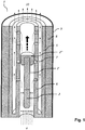
- the transport device is characterized in that the tubular transport channel 3 comprises a pipe system which has a gas-tight outer pipe 5 with an outer diameter D a and an inner diameter d a and an inner pipe 6 arranged coaxially thereto with an outer diameter D i ⁇ d a and an inner diameter d i wherein the inner diameter d i of the inner tube 6 is selected greater than or equal to the outer diameter D P of the NMR measurement samples 2, and that the inner tube 6 has transverse bores 7 which are spaced apart from one another in the axial direction and are designed as through bores .
- the transverse bores 7 can in principle be provided at any axial positions of the inner tube 6.
- the in Fig. 1 However, they are arranged equidistantly in the axial direction of the inner tube 6 in the illustrated embodiment of the invention.
- the transport device comprises a device 10 for generating negative pressure in the end of the tubular transport channel 3 facing the NMR spectrometer.
- the "pseudo-conical" double pipe system 5, 6 can therefore both be blown on by means of the device 4 and sucked off by the device 10.
- the NMR measurement samples 2 are each in operation in a preferably cylindrical sample tube 2 ' with an outer diameter D PR .
- these sample tubes 2 ' are each closed in a fluid-tight manner by a closure cap 2 " with a maximum outer diameter D VK attached to one side.
- the sample tubes 2' and the closure caps 2" are dimensioned such that: d i ⁇ D VK > D PR .
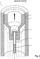
- Fig. 2 represents a transport device according to the prior art.
- the double tube system 5, 6 according to the invention is missing here. Instead, the sample tube 2 'with its closure cap 2 "is surrounded by a transport container 12 , which is guided on its outer contour radially within a standard transport tube 11 .
- the double pipe system 5, 6 of the transport device according to the invention can also be arranged radially within an existing conventional standard transport pipe 11 according to the prior art, thus making it incompatible with existing devices will be produced.
- the NMR measurement samples 2 can likewise be surrounded by a transport container 12 during operation.
- M T mass of transport containers
- M T ⁇ 50g in particular M T ⁇ 40g, preferably M T 25g.
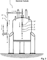
- Fig. 3 shows an NMR spectrometer 1 with a transport device according to the prior art, which instead could, however, also be exchanged for a transport device according to the invention.
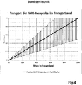
- Fig. 4 the relationship between the distance covered by the NMR measurement sample in a transport device according to the prior art and the size of the gas flow is shown graphically with corresponding error bars for the axial position of the NMR measurement sample.
- Fig. 5 finally, shows the relationship between the distance covered by the NMR measurement sample in a transport device according to the invention and the size of the gas flow with corresponding error bars for the axial position of the NMR measurement sample.
- the above-described modification of the transport device according to the invention creates a fixed relationship between the gas flow and the position of the NMR measurement sample 2 in the transport channel 3, which is shown in FIG Fig. 5 is shown as a stepped curve. Each step corresponds to a position with the transverse holes 7 in the inner transport tube 6. As can be clearly seen, the height of the error bars remains in Fig. 5 The same size over the entire transport distance. The respective current position of the NMR measurement sample 2 is thus always fairly precisely defined during its transport.
- the total mass of the NMR measurement sample 2 to be transported is very small. Therefore a high dynamic can be achieved with at the same time the smallest risk of damage to the NMR measurement sample.
- the possible complete elimination of the transport carrier also allows the inner tube 6 and thus also the transport channel 3 to be dimensioned extremely small (typically 9mm instead of the previous 26mm). This creates a lot of additional space that can be used, for example, for thermal insulation 8 from the NMR magnet and for an additional protective cover 9. In this way, undesired temperature changes in the NMR measurement sample 2 during the transport into the NMR spectrometer 1 can be reduced even further.
Landscapes
- Physics & Mathematics (AREA)
- Condensed Matter Physics & Semiconductors (AREA)
- General Physics & Mathematics (AREA)
- Spectroscopy & Molecular Physics (AREA)
- High Energy & Nuclear Physics (AREA)
- Other Investigation Or Analysis Of Materials By Electrical Means (AREA)
- Sampling And Sample Adjustment (AREA)
Claims (15)
- Dispositif de transport affecté au convoyage pneumatique d'échantillons de mesure RMN (2) vers un spectromètre RMN (1) à partir d'une région située à l'extérieur dudit spectromètre RMN (1), par l'intermédiaire d'un canal tubulaire de transport (3), puis de nouveau vers l'extérieur dudit spectromètre RMN (1), ledit dispositif de transport incluant un appareil (4) générateur de surpression dans l'extrémité dudit canal tubulaire de transport (3) qui pointe à l'opposé dudit spectromètre RMN,
caractérisé par le fait
que le canal tubulaire de transport (3) inclut un système de tubulures (5, 6) comprenant une tubulure extérieure (5) étanche aux gaz, munie d'un diamètre extérieur Da et d'un diamètre intérieur da, ainsi qu'une tubulure intérieure (6) qui est disposée coaxialement à la tubulure précitée, présente un diamètre extérieur Di < da et un diamètre intérieur di, et par l'intermédiaire de laquelle les échantillons de mesure sont convoyés en service ;
et par le fait que ladite tubulure intérieure (6) est pourvue d'alésages transversaux (7) espacés les uns des autres dans la direction axiale et conçus comme des alésages traversants. - Dispositif de transport selon la revendication 1, caractérisé par le fait que les alésages transversaux (7) sont agencés à équidistance dans la direction axiale de la tubulure intérieure (6).
- Dispositif de transport selon l'une des revendications précédentes, caractérisé par la présence d'un dispositif d'isolation thermique (8) entourant la tubulure extérieure (5).
- Dispositif de transport selon l'une des revendications précédentes, caractérisé par le fait qu'une enveloppe protectrice (9) entoure le système de tubulures (5, 6).
- Dispositif de transport selon l'une des revendications précédentes, caractérisé par le fait que ledit dispositif de transport inclut un appareil (10) générateur de dépression dans l'extrémité du canal tubulaire de transport (3) qui pointe vers le spectromètre RMN
- Dispositif de transport selon l'une des revendications précédentes, caractérisé par le fait que le système de tubulures (5, 6) peut être logé radialement à l'intérieur d'un tube de transport (11) standard, conforme à l'art antérieur.
- Dispositif de transport selon l'une des revendications précédentes, caractérisé par le fait que le système de tubulures (5, 6) présente les dimensionnements suivants :diamètre extérieur Da de la tubulure extérieure (5) : 15mm ≤ Da ≤ 30mm, de préférence 18mm ≤ Da ≤ 26mm;diamètre intérieur da de ladite tubulure extérieure (5) : 10mm ≤ da ≤ 25mm, de préférence 15mm ≤ da ≤ 20mm ;diamètre extérieur Di de la tubulure intérieure (6) : 7,5mm ≤ Di ≤ 15mm, de préférence 10mm ≤ Di ≤ 12mm ;diamètre intérieur di de ladite tubulure intérieure (6) : 5mm ≤ di ≤ 10mm, de préférence 8,5mm ≤ di ≤ 9,5mm ;espacement axial AQ des alésages transversaux (7) : 50mm ≤ AQ ≤ 300mm.
- Système comprenant un dispositif de transport conforme à l'une des revendications précédentes, ainsi que des échantillons de mesure RMN (2), caractérisé par le fait que les échantillons de mesure RMN (2) sont entourés, en vue de l'actionnement, par un conteneur de transport (12) dont la masse MT << 50g, en particulier MT < 40g, de préférence MT ≤ 25g.
- Système comprenant un dispositif de transport conforme à l'une des revendications précédentes, ainsi que des échantillons de mesure RMN (2), caractérisé par le fait que les échantillons de mesure RMN (2) sont logés à chaque fois, en vue de l'actionnement, dans un tube à essai (2') préférentiellement cylindrique, muni d'un diamètre extérieur DPR ; et par le fait que les tubes à essai (2') sont respectivement obturés de manière étanche aux fluides, en vue de l'actionnement, par un capuchon obturateur (2") mis en place d'un côté et muni d'un diamètre extérieur maximal DVK.
- Système selon la revendication 9, caractérisé par le fait que les tubes à essai (2') et les capuchons obturateurs (2") sont dimensionnés de manière qu'il soit satisfait à : di ≥ DVK > DPR.
- Procédé dédié à l'actionnement d'un dispositif de transport conforme à l'une des revendications 1 à 7, respectivement d'un système conforme à l'une des revendications 8 à 10, caractérisé par les étapes suivantes :(a) amenée d'un échantillon de mesure RMN (2) prélevé d'un poste d'alimentation situé à l'extérieur du spectromètre RMN (1), par l'intermédiaire de la partie externe du canal de transport (3), vers le point d'entrée dans ledit spectromètre RMN (1) ;(b) transfert dudit échantillon de mesure RMN (2) à une position spatiale propice à la poursuite du transport jusque dans l'aimant RMN ;(c) introduction dudit échantillon de mesure RMN (2) contrôlée pneumatiquement, par l'intermédiaire de la partie interne dudit canal de transport, dans le centre de l'aimant du système magnétique RMN ;(d) exécution d'une mesure RMN sur ledit échantillon de mesure RMN (2) ;(e) transport pneumatique de retour dudit échantillon de mesure RMN (2) vers l'extérieur dudit spectromètre RMN (1), à partir dudit centre de l'aimant ;(f) poursuite du transport de retour dudit échantillon de mesure RMN (2) mesuré, vers ledit poste d'alimentation, par l'intermédiaire de ladite partie externe dudit canal de transport (3).
- Procédé selon la revendication 11, dédié à l'actionnement d'un dispositif de transport conforme à la revendication 2 et, le cas échéant, à l'une des revendications 3 à 10, caractérisé par le fait que, sur la base du rapport entre l'air sortant des alésages transversaux (7) et le débit volumique total, et de la corrélation directe qui en résulte, entre ledit débit volumique total et l'emplacement axial d'un échantillon de mesure RMN (2) dans le canal de transport (3), il s'opère un calcul de l'emplacement axial instantané dudit échantillon de mesure RMN (2).
- Procédé selon la revendication 11 ou 12, dédié à l'actionnement d'un dispositif de transport conforme à la revendication 3 et, le cas échéant, à l'une des revendications 4 à 10, caractérisé par le fait que lors de la mesure RMN, en tirant parti du dispositif d'isolation thermique (8) entourant la tubulure extérieure (5), la tubulure intérieure (6) est maintenue à une température constante, de préférence à la température de l'échantillon de mesure RMN (2), cette température étant isolée thermiquement vis-à-vis de la température non régulée du canal de transport (3).
- Procédé selon l'une des revendications 11 à 13, dédié à l'actionnement d'un dispositif de transport conforme à la revendication 5 et, le cas échéant, à l'une des revendications 6 à 10, caractérisé par le fait que pour l'exécution d'une mesure RMN, en plus d'une insufflation effectuée par l'appareil (4) générateur de surpression, l'échantillon de mesure RMN (2) est également aspiré dans le spectromètre RMN (1) au moyen de l'appareil (10) générateur de dépression.
- Spectromètre RMN (1) équipé d'un dispositif de transport conforme à l'une des revendications 1 à 7, respectivement d'un système conforme à l'une des revendications 8 à 10.
Applications Claiming Priority (1)
| Application Number | Priority Date | Filing Date | Title |
|---|---|---|---|
| DE102018205535.1A DE102018205535B3 (de) | 2018-04-12 | 2018-04-12 | Transporteinrichtung für temperierte NMR-Messproben mit Doppelrohrsystem |
Publications (2)
| Publication Number | Publication Date |
|---|---|
| EP3553545A1 EP3553545A1 (fr) | 2019-10-16 |
| EP3553545B1 true EP3553545B1 (fr) | 2020-12-09 |
Family
ID=66092190
Family Applications (1)
| Application Number | Title | Priority Date | Filing Date |
|---|---|---|---|
| EP19167319.3A Active EP3553545B1 (fr) | 2018-04-12 | 2019-04-04 | Dispositif de transport pour échantillons de mesure rmn tempérés pourvu de système à tube double |
Country Status (3)
| Country | Link |
|---|---|
| US (1) | US10782369B2 (fr) |
| EP (1) | EP3553545B1 (fr) |
| DE (1) | DE102018205535B3 (fr) |
Cited By (1)
| Publication number | Priority date | Publication date | Assignee | Title |
|---|---|---|---|---|
| EP4679121A1 (fr) | 2024-07-11 | 2026-01-14 | Bruker Switzerland AG | Appareil rmn avec tube flexible pour le transport d'échantillons |
Families Citing this family (3)
| Publication number | Priority date | Publication date | Assignee | Title |
|---|---|---|---|---|
| CN115078436B (zh) * | 2022-06-14 | 2025-05-06 | 上海科技大学 | 一种适用于固体核磁共振研究的生物样品封装转移方法和配套离心装置 |
| DE102022210010A1 (de) | 2022-09-22 | 2024-03-28 | Bruker Switzerland Ag | Halterung von NMR-Messproben in einem Platz-beschränkten NMR-Spektrometer |
| US12467992B1 (en) | 2025-07-03 | 2025-11-11 | Bruker Switzerland Ag | NMR apparatus with flexible sample transport tube |
Family Cites Families (10)
| Publication number | Priority date | Publication date | Assignee | Title |
|---|---|---|---|---|
| DE3729819A1 (de) | 1987-09-05 | 1989-03-16 | Spectrospin Ag | Magnetanordnung fuer nmr-spektrometer |
| DE10111674C2 (de) * | 2001-03-09 | 2003-02-06 | Bruker Biospin Ag Faellanden | Vorrichtung zum Transport sowie zur exakten Positionierung eines Probengläschens in einem hochauflösenden NRM-Spektrometer |
| US6768305B1 (en) | 2003-09-26 | 2004-07-27 | Varian, Inc. | Temperature controlled sample changer for NMR analysis |
| JP4291304B2 (ja) * | 2005-07-11 | 2009-07-08 | 株式会社日立製作所 | Nmrプローブ |
| DE102008063703B3 (de) | 2008-12-19 | 2010-06-17 | Bruker Biospin Ag | Automatische Transportvorrichtung für NMR-Messproben, Kryomagnetsystem mit automatischer Transportvorrichtung, Transportbehälter für automatische Transportvorrichtung und Verfahren zum Befördern einer NMR-Messprobe |
| DE102013212312B4 (de) * | 2013-06-26 | 2017-02-02 | Bruker Biospin Ag | NMR-Probenkopf mit verbesserter Zentrierung des Probenröhrchens |
| US20150198681A1 (en) * | 2014-01-15 | 2015-07-16 | Prudhvi Raju Chintalapati | Method for transporting an NMR sample spaced horizontally and vertically from a cryo-magnetic system using a vibration isolated motorized curvilinear Transport Carrier with dual end-effector and method for telescoping the Carrier to different cryo-magnetic systems at different heights |
| DE102014201076B3 (de) | 2014-01-22 | 2015-03-05 | Bruker Biospin Ag | Transportbehälter für einen NMR MAS-Rotor |
| US10281416B2 (en) * | 2014-08-04 | 2019-05-07 | Waters Technologies Corporation | Devices for use in solid-state NMR analysis |
| JP6528041B2 (ja) * | 2015-02-06 | 2019-06-12 | 日本電子株式会社 | Nmrプローブ |
-
2018
- 2018-04-12 DE DE102018205535.1A patent/DE102018205535B3/de not_active Expired - Fee Related
-
2019
- 2019-04-04 EP EP19167319.3A patent/EP3553545B1/fr active Active
- 2019-04-11 US US16/381,054 patent/US10782369B2/en active Active
Non-Patent Citations (1)
| Title |
|---|
| None * |
Cited By (1)
| Publication number | Priority date | Publication date | Assignee | Title |
|---|---|---|---|---|
| EP4679121A1 (fr) | 2024-07-11 | 2026-01-14 | Bruker Switzerland AG | Appareil rmn avec tube flexible pour le transport d'échantillons |
Also Published As
| Publication number | Publication date |
|---|---|
| DE102018205535B3 (de) | 2019-07-04 |
| EP3553545A1 (fr) | 2019-10-16 |
| US10782369B2 (en) | 2020-09-22 |
| US20190317162A1 (en) | 2019-10-17 |
Similar Documents
| Publication | Publication Date | Title |
|---|---|---|
| EP3553545B1 (fr) | Dispositif de transport pour échantillons de mesure rmn tempérés pourvu de système à tube double | |
| DE102014201076B3 (de) | Transportbehälter für einen NMR MAS-Rotor | |
| DE10111674C2 (de) | Vorrichtung zum Transport sowie zur exakten Positionierung eines Probengläschens in einem hochauflösenden NRM-Spektrometer | |
| EP3162443B1 (fr) | Guide d'aiguille pour centrer le perçage d'un septum | |
| DE69905713T2 (de) | Behälter mit kontrolliertem volumen für mikrowellen assistierte chemische prozesse | |
| EP2344620B1 (fr) | Dispositif de culture/d'exposition pour des cultures de cellules et/ou de bactéries | |
| EP3175279B1 (fr) | Microscope optique muni d'une platine porte-échantillon pour la cryomicroscopie | |
| DE19509062A1 (de) | NMR-Probenhalter | |
| DE102014106582B4 (de) | Füllnadel zum Befüllen eines Behälters mit einem Fluid | |
| EP3715893A1 (fr) | Spectromètre rmn pourvu de système de changement rapide pour échantillons | |
| DE10130283C1 (de) | NMR-Probenhalter und zugehörige Betriebsverfahren | |
| DE102015103657A1 (de) | Thermoanalysator | |
| DE4018734A1 (de) | Probentemperiervorrichtung | |
| EP3093679B1 (fr) | Stator pour ram avec dispositif d'aspiration | |
| DE102009016364B4 (de) | Kultur-/Expositionsvorrichtung, insbesondere für Zell- und/oder Bakterienkulturen | |
| DE102013219453B3 (de) | DNP-Vorrichtung | |
| EP2394158B1 (fr) | Dispositif et procédé de préparation d'échantillons pour la chromatographie gazeuse | |
| DE102016203891A1 (de) | Verfahren zur Durchführung einer NMR-Messung, Probenkopfanordnung für ein NMR-Spektrometer und NMR-Spektrometer-Anordnung | |
| EP3889630B1 (fr) | Rotor rmn magnétiquement compensé et procédé de conception et de fabrication | |
| DE102012101469B4 (de) | Wandfreie Klimakammer für einen akustischen Levitator | |
| AT515767B1 (de) | Materialprüfungsverfahren, Verwendung einer Ziehsteinanordnung und Ziehsteinanordnung | |
| EP2203732A2 (fr) | Sonde pour prélever des échantillons de laitier | |
| EP3048614A1 (fr) | Procede et dispositif d'encapsulage d'une barre de combustible ou d'une section de barre de combustible pour un stockage temporaire | |
| DE19612265C2 (de) | Verfahren zur Herstellung eines Mikrovials | |
| EP4145164B1 (fr) | Dispositif de couplage pour une cellule d'écoulement rmn destiné à l'alignement indépendant du champ magnétique et spectromètre rmn |
Legal Events
| Date | Code | Title | Description |
|---|---|---|---|
| PUAI | Public reference made under article 153(3) epc to a published international application that has entered the european phase |
Free format text: ORIGINAL CODE: 0009012 |
|
| STAA | Information on the status of an ep patent application or granted ep patent |
Free format text: STATUS: THE APPLICATION HAS BEEN PUBLISHED |
|
| AK | Designated contracting states |
Kind code of ref document: A1 Designated state(s): AL AT BE BG CH CY CZ DE DK EE ES FI FR GB GR HR HU IE IS IT LI LT LU LV MC MK MT NL NO PL PT RO RS SE SI SK SM TR |
|
| AX | Request for extension of the european patent |
Extension state: BA ME |
|
| RAP1 | Party data changed (applicant data changed or rights of an application transferred) |
Owner name: BRUKER SWITZERLAND AG |
|
| STAA | Information on the status of an ep patent application or granted ep patent |
Free format text: STATUS: REQUEST FOR EXAMINATION WAS MADE |
|
| 17P | Request for examination filed |
Effective date: 20191213 |
|
| RBV | Designated contracting states (corrected) |
Designated state(s): AL AT BE BG CH CY CZ DE DK EE ES FI FR GB GR HR HU IE IS IT LI LT LU LV MC MK MT NL NO PL PT RO RS SE SI SK SM TR |
|
| GRAP | Despatch of communication of intention to grant a patent |
Free format text: ORIGINAL CODE: EPIDOSNIGR1 |
|
| STAA | Information on the status of an ep patent application or granted ep patent |
Free format text: STATUS: GRANT OF PATENT IS INTENDED |
|
| RIC1 | Information provided on ipc code assigned before grant |
Ipc: G01R 33/31 20060101ALN20200923BHEP Ipc: G01R 33/30 20060101AFI20200923BHEP |
|
| GRAS | Grant fee paid |
Free format text: ORIGINAL CODE: EPIDOSNIGR3 |
|
| GRAA | (expected) grant |
Free format text: ORIGINAL CODE: 0009210 |
|
| STAA | Information on the status of an ep patent application or granted ep patent |
Free format text: STATUS: THE PATENT HAS BEEN GRANTED |
|
| INTG | Intention to grant announced |
Effective date: 20201019 |
|
| AK | Designated contracting states |
Kind code of ref document: B1 Designated state(s): AL AT BE BG CH CY CZ DE DK EE ES FI FR GB GR HR HU IE IS IT LI LT LU LV MC MK MT NL NO PL PT RO RS SE SI SK SM TR |
|
| REG | Reference to a national code |
Ref country code: GB Ref legal event code: FG4D Free format text: NOT ENGLISH |
|
| REG | Reference to a national code |
Ref country code: CH Ref legal event code: EP Ref country code: AT Ref legal event code: REF Ref document number: 1343975 Country of ref document: AT Kind code of ref document: T Effective date: 20201215 |
|
| REG | Reference to a national code |
Ref country code: DE Ref legal event code: R096 Ref document number: 502019000496 Country of ref document: DE |
|
| REG | Reference to a national code |
Ref country code: IE Ref legal event code: FG4D Free format text: LANGUAGE OF EP DOCUMENT: GERMAN |
|
| PG25 | Lapsed in a contracting state [announced via postgrant information from national office to epo] |
Ref country code: GR Free format text: LAPSE BECAUSE OF FAILURE TO SUBMIT A TRANSLATION OF THE DESCRIPTION OR TO PAY THE FEE WITHIN THE PRESCRIBED TIME-LIMIT Effective date: 20210310 Ref country code: NO Free format text: LAPSE BECAUSE OF FAILURE TO SUBMIT A TRANSLATION OF THE DESCRIPTION OR TO PAY THE FEE WITHIN THE PRESCRIBED TIME-LIMIT Effective date: 20210309 Ref country code: RS Free format text: LAPSE BECAUSE OF FAILURE TO SUBMIT A TRANSLATION OF THE DESCRIPTION OR TO PAY THE FEE WITHIN THE PRESCRIBED TIME-LIMIT Effective date: 20201209 Ref country code: FI Free format text: LAPSE BECAUSE OF FAILURE TO SUBMIT A TRANSLATION OF THE DESCRIPTION OR TO PAY THE FEE WITHIN THE PRESCRIBED TIME-LIMIT Effective date: 20201209 |
|
| PG25 | Lapsed in a contracting state [announced via postgrant information from national office to epo] |
Ref country code: BG Free format text: LAPSE BECAUSE OF FAILURE TO SUBMIT A TRANSLATION OF THE DESCRIPTION OR TO PAY THE FEE WITHIN THE PRESCRIBED TIME-LIMIT Effective date: 20210309 Ref country code: SE Free format text: LAPSE BECAUSE OF FAILURE TO SUBMIT A TRANSLATION OF THE DESCRIPTION OR TO PAY THE FEE WITHIN THE PRESCRIBED TIME-LIMIT Effective date: 20201209 Ref country code: LV Free format text: LAPSE BECAUSE OF FAILURE TO SUBMIT A TRANSLATION OF THE DESCRIPTION OR TO PAY THE FEE WITHIN THE PRESCRIBED TIME-LIMIT Effective date: 20201209 |
|
| REG | Reference to a national code |
Ref country code: NL Ref legal event code: MP Effective date: 20201209 |
|
| PG25 | Lapsed in a contracting state [announced via postgrant information from national office to epo] |
Ref country code: HR Free format text: LAPSE BECAUSE OF FAILURE TO SUBMIT A TRANSLATION OF THE DESCRIPTION OR TO PAY THE FEE WITHIN THE PRESCRIBED TIME-LIMIT Effective date: 20201209 Ref country code: NL Free format text: LAPSE BECAUSE OF FAILURE TO SUBMIT A TRANSLATION OF THE DESCRIPTION OR TO PAY THE FEE WITHIN THE PRESCRIBED TIME-LIMIT Effective date: 20201209 |
|
| REG | Reference to a national code |
Ref country code: LT Ref legal event code: MG9D |
|
| PG25 | Lapsed in a contracting state [announced via postgrant information from national office to epo] |
Ref country code: PT Free format text: LAPSE BECAUSE OF FAILURE TO SUBMIT A TRANSLATION OF THE DESCRIPTION OR TO PAY THE FEE WITHIN THE PRESCRIBED TIME-LIMIT Effective date: 20210409 Ref country code: RO Free format text: LAPSE BECAUSE OF FAILURE TO SUBMIT A TRANSLATION OF THE DESCRIPTION OR TO PAY THE FEE WITHIN THE PRESCRIBED TIME-LIMIT Effective date: 20201209 Ref country code: LT Free format text: LAPSE BECAUSE OF FAILURE TO SUBMIT A TRANSLATION OF THE DESCRIPTION OR TO PAY THE FEE WITHIN THE PRESCRIBED TIME-LIMIT Effective date: 20201209 Ref country code: CZ Free format text: LAPSE BECAUSE OF FAILURE TO SUBMIT A TRANSLATION OF THE DESCRIPTION OR TO PAY THE FEE WITHIN THE PRESCRIBED TIME-LIMIT Effective date: 20201209 Ref country code: SM Free format text: LAPSE BECAUSE OF FAILURE TO SUBMIT A TRANSLATION OF THE DESCRIPTION OR TO PAY THE FEE WITHIN THE PRESCRIBED TIME-LIMIT Effective date: 20201209 Ref country code: SK Free format text: LAPSE BECAUSE OF FAILURE TO SUBMIT A TRANSLATION OF THE DESCRIPTION OR TO PAY THE FEE WITHIN THE PRESCRIBED TIME-LIMIT Effective date: 20201209 Ref country code: EE Free format text: LAPSE BECAUSE OF FAILURE TO SUBMIT A TRANSLATION OF THE DESCRIPTION OR TO PAY THE FEE WITHIN THE PRESCRIBED TIME-LIMIT Effective date: 20201209 |
|
| PG25 | Lapsed in a contracting state [announced via postgrant information from national office to epo] |
Ref country code: PL Free format text: LAPSE BECAUSE OF FAILURE TO SUBMIT A TRANSLATION OF THE DESCRIPTION OR TO PAY THE FEE WITHIN THE PRESCRIBED TIME-LIMIT Effective date: 20201209 |
|
| REG | Reference to a national code |
Ref country code: DE Ref legal event code: R097 Ref document number: 502019000496 Country of ref document: DE |
|
| PG25 | Lapsed in a contracting state [announced via postgrant information from national office to epo] |
Ref country code: IS Free format text: LAPSE BECAUSE OF FAILURE TO SUBMIT A TRANSLATION OF THE DESCRIPTION OR TO PAY THE FEE WITHIN THE PRESCRIBED TIME-LIMIT Effective date: 20210409 |
|
| PLBE | No opposition filed within time limit |
Free format text: ORIGINAL CODE: 0009261 |
|
| STAA | Information on the status of an ep patent application or granted ep patent |
Free format text: STATUS: NO OPPOSITION FILED WITHIN TIME LIMIT |
|
| PG25 | Lapsed in a contracting state [announced via postgrant information from national office to epo] |
Ref country code: IT Free format text: LAPSE BECAUSE OF FAILURE TO SUBMIT A TRANSLATION OF THE DESCRIPTION OR TO PAY THE FEE WITHIN THE PRESCRIBED TIME-LIMIT Effective date: 20201209 Ref country code: AL Free format text: LAPSE BECAUSE OF FAILURE TO SUBMIT A TRANSLATION OF THE DESCRIPTION OR TO PAY THE FEE WITHIN THE PRESCRIBED TIME-LIMIT Effective date: 20201209 |
|
| 26N | No opposition filed |
Effective date: 20210910 |
|
| PG25 | Lapsed in a contracting state [announced via postgrant information from national office to epo] |
Ref country code: MC Free format text: LAPSE BECAUSE OF FAILURE TO SUBMIT A TRANSLATION OF THE DESCRIPTION OR TO PAY THE FEE WITHIN THE PRESCRIBED TIME-LIMIT Effective date: 20201209 Ref country code: SI Free format text: LAPSE BECAUSE OF FAILURE TO SUBMIT A TRANSLATION OF THE DESCRIPTION OR TO PAY THE FEE WITHIN THE PRESCRIBED TIME-LIMIT Effective date: 20201209 Ref country code: DK Free format text: LAPSE BECAUSE OF FAILURE TO SUBMIT A TRANSLATION OF THE DESCRIPTION OR TO PAY THE FEE WITHIN THE PRESCRIBED TIME-LIMIT Effective date: 20201209 |
|
| PG25 | Lapsed in a contracting state [announced via postgrant information from national office to epo] |
Ref country code: LU Free format text: LAPSE BECAUSE OF NON-PAYMENT OF DUE FEES Effective date: 20210404 |
|
| REG | Reference to a national code |
Ref country code: BE Ref legal event code: MM Effective date: 20210430 |
|
| PG25 | Lapsed in a contracting state [announced via postgrant information from national office to epo] |
Ref country code: ES Free format text: LAPSE BECAUSE OF FAILURE TO SUBMIT A TRANSLATION OF THE DESCRIPTION OR TO PAY THE FEE WITHIN THE PRESCRIBED TIME-LIMIT Effective date: 20201209 |
|
| PG25 | Lapsed in a contracting state [announced via postgrant information from national office to epo] |
Ref country code: IE Free format text: LAPSE BECAUSE OF NON-PAYMENT OF DUE FEES Effective date: 20210404 |
|
| PG25 | Lapsed in a contracting state [announced via postgrant information from national office to epo] |
Ref country code: IS Free format text: LAPSE BECAUSE OF FAILURE TO SUBMIT A TRANSLATION OF THE DESCRIPTION OR TO PAY THE FEE WITHIN THE PRESCRIBED TIME-LIMIT Effective date: 20210409 |
|
| PG25 | Lapsed in a contracting state [announced via postgrant information from national office to epo] |
Ref country code: BE Free format text: LAPSE BECAUSE OF NON-PAYMENT OF DUE FEES Effective date: 20210430 |
|
| PG25 | Lapsed in a contracting state [announced via postgrant information from national office to epo] |
Ref country code: CY Free format text: LAPSE BECAUSE OF FAILURE TO SUBMIT A TRANSLATION OF THE DESCRIPTION OR TO PAY THE FEE WITHIN THE PRESCRIBED TIME-LIMIT Effective date: 20201209 |
|
| PG25 | Lapsed in a contracting state [announced via postgrant information from national office to epo] |
Ref country code: HU Free format text: LAPSE BECAUSE OF FAILURE TO SUBMIT A TRANSLATION OF THE DESCRIPTION OR TO PAY THE FEE WITHIN THE PRESCRIBED TIME-LIMIT; INVALID AB INITIO Effective date: 20190404 |
|
| P01 | Opt-out of the competence of the unified patent court (upc) registered |
Effective date: 20231221 |
|
| PG25 | Lapsed in a contracting state [announced via postgrant information from national office to epo] |
Ref country code: MK Free format text: LAPSE BECAUSE OF FAILURE TO SUBMIT A TRANSLATION OF THE DESCRIPTION OR TO PAY THE FEE WITHIN THE PRESCRIBED TIME-LIMIT Effective date: 20201209 |
|
| PG25 | Lapsed in a contracting state [announced via postgrant information from national office to epo] |
Ref country code: MT Free format text: LAPSE BECAUSE OF FAILURE TO SUBMIT A TRANSLATION OF THE DESCRIPTION OR TO PAY THE FEE WITHIN THE PRESCRIBED TIME-LIMIT Effective date: 20201209 |
|
| REG | Reference to a national code |
Ref country code: AT Ref legal event code: MM01 Ref document number: 1343975 Country of ref document: AT Kind code of ref document: T Effective date: 20240404 |
|
| PGFP | Annual fee paid to national office [announced via postgrant information from national office to epo] |
Ref country code: DE Payment date: 20250417 Year of fee payment: 7 |
|
| PGFP | Annual fee paid to national office [announced via postgrant information from national office to epo] |
Ref country code: GB Payment date: 20250423 Year of fee payment: 7 |
|
| PGFP | Annual fee paid to national office [announced via postgrant information from national office to epo] |
Ref country code: FR Payment date: 20250422 Year of fee payment: 7 |
|
| PGFP | Annual fee paid to national office [announced via postgrant information from national office to epo] |
Ref country code: CH Payment date: 20250501 Year of fee payment: 7 |
|
| PG25 | Lapsed in a contracting state [announced via postgrant information from national office to epo] |
Ref country code: AT Free format text: LAPSE BECAUSE OF NON-PAYMENT OF DUE FEES Effective date: 20240404 |
|
| PG25 | Lapsed in a contracting state [announced via postgrant information from national office to epo] |
Ref country code: TR Free format text: LAPSE BECAUSE OF FAILURE TO SUBMIT A TRANSLATION OF THE DESCRIPTION OR TO PAY THE FEE WITHIN THE PRESCRIBED TIME-LIMIT Effective date: 20201209 |