EP2168409B1 - Dispositif de production d'un jet de plasma - Google Patents
Dispositif de production d'un jet de plasma Download PDFInfo
- Publication number
- EP2168409B1 EP2168409B1 EP08759132A EP08759132A EP2168409B1 EP 2168409 B1 EP2168409 B1 EP 2168409B1 EP 08759132 A EP08759132 A EP 08759132A EP 08759132 A EP08759132 A EP 08759132A EP 2168409 B1 EP2168409 B1 EP 2168409B1
- Authority
- EP
- European Patent Office
- Prior art keywords
- counter electrode
- discharge tube
- fact
- plasma
- plasma jet
- Prior art date
- Legal status (The legal status is an assumption and is not a legal conclusion. Google has not performed a legal analysis and makes no representation as to the accuracy of the status listed.)
- Not-in-force
Links
Images

Classifications
-
- H—ELECTRICITY
- H05—ELECTRIC TECHNIQUES NOT OTHERWISE PROVIDED FOR
- H05H—PLASMA TECHNIQUE; PRODUCTION OF ACCELERATED ELECTRICALLY-CHARGED PARTICLES OR OF NEUTRONS; PRODUCTION OR ACCELERATION OF NEUTRAL MOLECULAR OR ATOMIC BEAMS
- H05H1/00—Generating plasma; Handling plasma
- H05H1/24—Generating plasma
- H05H1/26—Plasma torches
- H05H1/28—Cooling arrangements
-
- H—ELECTRICITY
- H05—ELECTRIC TECHNIQUES NOT OTHERWISE PROVIDED FOR
- H05H—PLASMA TECHNIQUE; PRODUCTION OF ACCELERATED ELECTRICALLY-CHARGED PARTICLES OR OF NEUTRONS; PRODUCTION OR ACCELERATION OF NEUTRAL MOLECULAR OR ATOMIC BEAMS
- H05H1/00—Generating plasma; Handling plasma
- H05H1/24—Generating plasma
- H05H1/2406—Generating plasma using dielectric barrier discharges, i.e. with a dielectric interposed between the electrodes
- H05H1/2443—Generating plasma using dielectric barrier discharges, i.e. with a dielectric interposed between the electrodes the plasma fluid flowing through a dielectric tube
Definitions
- the invention relates to a device for generating a plasma jet.
- Such a device is from the not yet pre-published German priority application DE 10 2006 012 100.7-54 known. It has a discharge tube made of dielectric material, in the interior of which an inner, rod-shaped, solid electrode is arranged to extend in the longitudinal direction. A second electrode comprises the discharge tube. This can be done directly or at a radial distance. To generate the plasma jet, the inner rod-shaped electrode is set to high voltage while the outer electrode is grounded. Due to the conditions of the electric field, this leads to a dielectrically impeded discharge and preferably to an ignition of the plasma at the tip of the inner rod-shaped electrode.
- a cap made of dielectric material is provided at the end of the discharge tube.
- the plasma generated in this case is "cold plasma” under atmospheric pressure, which has a gennge gas temperature, up to a few hundred degrees Celsius.
- a disadvantage of this known cooling system is the enormous structural complexity that must be operated in order to prevent a potential carryover between the different potentials of the tungsten electrode and the plasma nozzle of the plasma torch. Also, it is not desirable in the course of reliability, in an electrical system in which very high electrical currents and voltages occur to use an electrically conductive fluid, here water, as a coolant.
- J. Toshifuji at al .; Surface End Coatings Technology 171 (2003) 302-306 discloses an apparatus for producing a plasma jet having a dielectric discharge tube, a center electrode and a second concentric counter electrode.
- DE 2654485 discloses a cooling device in a plasma torch. The object of the invention is therefore to provide a device for generating a plasma jet of the type mentioned above with an additional cooling arrangement, in which there is no thermal overload despite high coupled power. Furthermore, it is an object of the invention to find a structurally simple and operationally safe solution for it.
- the device according to the invention with a cooling arrangement has a counterelectrode which is designed such that it forms a surface segmentation or enlargement, for example in the ignition region of the plasma.
- a heat sink is arranged on the counterelectrode.
- an electrical temperature sensor is provided on the cooling arrangement, which is part of a control loop and ensures that the thermal load of the system does not exceed a previously defined limit temperature.
- the heat sink is designed so that it both as a holder of the device in automated manufacturing equipment serves, as well as the inclusion of the temperature sensor allows.
- FIG. 1 It shows a discharge tube 1 of dielectric material, inside which a central, rod-shaped center electrode 2 is arranged, which simultaneously embodies a vertical central axis.
- a second electrode 3, which forms the counterelectrode to the central center electrode 2 is rotationally symmetrical, so that the dielectric discharge tube 1, the central center electrode 2 and the counterelectrode 3 form a coaxial structure with an open end face on which the plasma jet, ie the actual plasma beam is generated.
- the central center electrode 2 is set to high voltage, while the outer counter electrode 3 is grounded.
- the counterelectrode 3 On the side facing away from the central center electrode 2, the counterelectrode 3 has an encircling, radial segmentation 5 in the form of cooling fins in the region of the plasma coupling.
- an electrical temperature sensor 9 is integrated, which is part of an electrical control circuit and ensures that the thermal load of the system does not exceed a previously defined limit temperature and if necessary, a forced shutdown of the system can be done as a safety measure.
- a deflection unit 10 is arranged, which leads an incoming air volume flow 11 to the opening of the heat sink 6.
- the air volume flow 11 is variably adjustable and freely definable for the respective cooling demand. For example, if a higher power coupled into the device to get a more intense plasma jet, this inevitably causes a higher thermal stress on the components, especially in the field of plasma coupling. To counteract this effect, the air volume flow 11 must be increased in order to ensure sufficient cooling of the components by means of the heat sink 6 according to the invention and the circumferential segmentation 5 of the counter electrode 3. Thus, it is possible to drive a temperature curve controlled and defined in cooperation with the temperature sensor 9 for the respective cooling requirement.
- the heat sink 6 and the deflection unit 10 are designed such that they serve both as a machine holder of the device in automated manufacturing facilities, as well as allow the recording of the temperature sensor 9 at the same time.
- a dielectric end cap 4 is attached to the discharge tube 1 at the open end side, which is fastened by screwing to the counter electrode 3.
- the end cap 4 is z. Example of Teflon or other plastic with appropriate thermal and mechanical stability, but alternatively also of ceramic.
- d. H. prevents a direct arc between the central center electrode 2 and the grounded counter electrode 3, since the distance between these two electrodes is now much larger electrically.
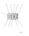
- FIG. 2 shows a cooling arrangement according to the invention for a device for generating a plasma jet in a sectional view.
- the center electrode 2 is visible, which is constructed concentrically with the discharge tube 1 and the counter electrode 3 and is operatively connected.
- the air volume flow 11 flowing in via the air supply channel 12 and still bundled in this area is guided via the deflection unit 10 to the air inlet 7 of the heat sink 6 and split onto the existing segments of the cooling fins 5 of the counter electrode 3.
- FIG. 2 exemplarily the course of the air convection 13 for a segment of the cooling fins 5 visible.
- the incoming air at the air inlet 7 flows over the segment of the cooling fin 5 and the counter electrode 3, heats up by absorbing the thermal energy generated during the plasma coupling and then flows through a possible outlet of the openings of the air outlet 8.
- the air outlet 8 exemplarily the course of the air flow possible.
Claims (5)
- Dispositif servant à générer un jet de plasma avec au moins un tube de décharge (1), la paroi du tube de décharge (1) étant constituée de matériau diélectrique, une première électrode (2) de construction pleine étant agencée au centre à l'intérieur du tube de décharge (1), s'étendant dans le sens longitudinal de celui-ci, une contre-électrode (3) enveloppant concentriquement la paroi du tube de décharge (1), de sorte que la première électrode (2), le tube de décharge (1) et la contre-électrode (3) forment une structure coaxiale et concentrique dans la section transversale avec une face avant ouverte, contre laquelle le jet de plasma peut être généré, caractérisé en ce que la contre-électrode (3) présente une segmentation radiale circulaire sur le côté opposé de la première électrode (2) et que sur la contre-électrode (3) est fixé sur le côté de la segmentation un corps réfrigérant (6) disposant d'au moins une entrée d'air (7) et d'au moins une sortie d'air (8) de façon à ce qu'il puisse être traversé par l'air.
- Dispositif selon la revendication 1,
caractérisé en ce que,
dans la zone de la segmentation (5) un capteur de température électrique (9) est installé, qui fait partie d'un circuit de réglage électrique. - Dispositif selon la revendication 1 ou 2,
caractérisé en ce que,
la segmentation radiale circulaire de la contre-électrode (3) est prévue dans zone de transmission du plasma. - Dispositif selon l'une des revendications 1 à 3,
caractérisé en ce que,
sur la face avant du dispositif sur laquelle peut être généré le jet de plasma, il est agencé un capuchon de recouvrement (4) diélectrique et concentrique qui enveloppe la contre-électrode (3) et sert d'accumulateur thermique. - Dispositif selon l'une des revendications 1 à 4,
caractérisé en ce que,
le corps réfrigérant (6) en plus de présenter un support pour le dispositif accueille également un capteur de température.
Applications Claiming Priority (2)
| Application Number | Priority Date | Filing Date | Title |
|---|---|---|---|
| DE102007032496A DE102007032496B3 (de) | 2007-07-12 | 2007-07-12 | Vorrichtung zur Erzeugung eines Plasma-Jets |
| PCT/EP2008/004605 WO2009006972A1 (fr) | 2007-07-12 | 2008-06-10 | Dispositif de production d'un jet de plasma |
Publications (2)
| Publication Number | Publication Date |
|---|---|
| EP2168409A1 EP2168409A1 (fr) | 2010-03-31 |
| EP2168409B1 true EP2168409B1 (fr) | 2012-12-26 |
Family
ID=39739298
Family Applications (1)
| Application Number | Title | Priority Date | Filing Date |
|---|---|---|---|
| EP08759132A Not-in-force EP2168409B1 (fr) | 2007-07-12 | 2008-06-10 | Dispositif de production d'un jet de plasma |
Country Status (3)
| Country | Link |
|---|---|
| EP (1) | EP2168409B1 (fr) |
| DE (1) | DE102007032496B3 (fr) |
| WO (1) | WO2009006972A1 (fr) |
Cited By (2)
| Publication number | Priority date | Publication date | Assignee | Title |
|---|---|---|---|---|
| WO2016146498A1 (fr) | 2015-03-17 | 2016-09-22 | Tesa Se | Traitement au plasma basse température |
| DE102016203413A1 (de) | 2016-03-02 | 2017-09-07 | Tesa Se | Erhöhung der Abzugskraft durch selektive Plasmavorbehandlung |
Families Citing this family (4)
| Publication number | Priority date | Publication date | Assignee | Title |
|---|---|---|---|---|
| TWI432228B (zh) * | 2010-09-07 | 2014-04-01 | Univ Nat Cheng Kung | 微電漿產生裝置及其滅菌系統 |
| DE102013017109A1 (de) * | 2013-10-15 | 2015-04-16 | Fraunhofer-Gesellschaft zur Förderung der angewandten Forschung e.V. | Verfahren und Vorrichtung zur Herstellung von Partikeln in einem Atmosphärendruckplasma |
| DE102022124117A1 (de) | 2022-09-20 | 2024-03-21 | Caphenia Gmbh | Plasma-Reaktor |
| CN117460142A (zh) * | 2023-09-22 | 2024-01-26 | 北京核力同创科技有限公司 | 一种多峰场负氢离子源引出结构 |
Family Cites Families (13)
| Publication number | Priority date | Publication date | Assignee | Title |
|---|---|---|---|---|
| BE566144A (fr) * | 1957-03-27 | |||
| FR1322260A (fr) * | 1962-02-14 | 1963-03-29 | Saint Gobain | Chalumeau à flamme de plasma |
| DE2651185A1 (de) * | 1976-11-10 | 1978-05-11 | Nuc Weld Gmbh | Kuehleinrichtung bei einem plasmabrenner |
| US4659899A (en) * | 1984-10-24 | 1987-04-21 | The Perkin-Elmer Corporation | Vacuum-compatible air-cooled plasma device |
| US4902871A (en) * | 1987-01-30 | 1990-02-20 | Hypertherm, Inc. | Apparatus and process for cooling a plasma arc electrode |
| US4912361A (en) * | 1988-07-18 | 1990-03-27 | Electro-Plasma, Inc. | Plasma gun having improved anode cooling system |
| US5008511C1 (en) * | 1990-06-26 | 2001-03-20 | Univ British Columbia | Plasma torch with axial reactant feed |
| TW315340B (fr) * | 1995-02-13 | 1997-09-11 | Komatsu Mfg Co Ltd | |
| DE19828633B4 (de) * | 1998-06-26 | 2004-07-29 | Wirth, Aloisia | Lichtbogenschweiß- oder -schneidbrenner sowie Kühlsystem, Plasmadüsen bzw. WIG-Elektrodenspannzangen, Spannsystem für Plasmaelektrodennadeln u. verfahrensübergreifendes Konstruktionsprinzip hierfür |
| DE29919142U1 (de) * | 1999-10-30 | 2001-03-08 | Agrodyn Hochspannungstechnik G | Plasmadüse |
| ATE434921T1 (de) * | 2000-03-31 | 2009-07-15 | Thermal Dynamics Corp | Lichtbogen-plasmabrenner und verfahren zur erhöhung der lebensdauer der verschleissteile eines lichtbogen-plasmabrenners |
| DE102005042955A1 (de) * | 2005-09-01 | 2007-03-15 | Tbi Industries Gmbh | Plasmaschweiß- und Schneidbrenner mit einem Kühlsystem |
| US7326377B2 (en) * | 2005-11-30 | 2008-02-05 | Honeywell International, Inc. | Solid-free-form fabrication process and apparatus including in-process workpiece cooling |
-
2007
- 2007-07-12 DE DE102007032496A patent/DE102007032496B3/de not_active Expired - Fee Related
-
2008
- 2008-06-10 WO PCT/EP2008/004605 patent/WO2009006972A1/fr active Application Filing
- 2008-06-10 EP EP08759132A patent/EP2168409B1/fr not_active Not-in-force
Cited By (4)
| Publication number | Priority date | Publication date | Assignee | Title |
|---|---|---|---|---|
| WO2016146498A1 (fr) | 2015-03-17 | 2016-09-22 | Tesa Se | Traitement au plasma basse température |
| DE102015204753A1 (de) | 2015-03-17 | 2016-10-20 | Tesa Se | Niedertemperatur-Plasma-Behandlung |
| DE102016203413A1 (de) | 2016-03-02 | 2017-09-07 | Tesa Se | Erhöhung der Abzugskraft durch selektive Plasmavorbehandlung |
| WO2017148763A1 (fr) | 2016-03-02 | 2017-09-08 | Tesa Se | Augmentation de la force d'arrachement par prétraitement sélectif au plasma |
Also Published As
| Publication number | Publication date |
|---|---|
| WO2009006972A1 (fr) | 2009-01-15 |
| EP2168409A1 (fr) | 2010-03-31 |
| DE102007032496B3 (de) | 2009-01-29 |
Similar Documents
| Publication | Publication Date | Title |
|---|---|---|
| DE102005023060B4 (de) | Gasentladungs-Strahlungsquelle, insbesondere für EUV-Strahlung | |
| EP2465334B1 (fr) | Capot de protection de buse et porte-capot de protection de buse ainsi que torche à plasma équipée de l'un et/ou de l'autre | |
| EP2168409B1 (fr) | Dispositif de production d'un jet de plasma | |
| DE102008018530B4 (de) | Düse für einen flüssigkeitsgekühlten Plasmabrenner, Anordnung aus derselben und einer Düsenkappe sowie flüssigkeitsgekühlter Plasmabrenner mit einer derartigen Anordnung | |
| DE2857787C2 (de) | Plasmastrahlbrennerkopf | |
| EP0585203B1 (fr) | Appareil de pulvérisation par plasma | |
| DE102009016932B4 (de) | Kühlrohre und Elektrodenaufnahme für einen Lichtbogenplasmabrenner sowie Anordnungen aus denselben und Lichtbogenplasmabrenner mit denselben | |
| DE102011088433A1 (de) | Verfahren und Plasmalichtbogenbrennersystem zum Markieren und Schneiden von Werkstücken mit dem selben Satz an Hilfsstoffen | |
| DE102007031534A1 (de) | Wolfram-Inertgas-Schweißbrenner | |
| EP0430367A2 (fr) | Tube à rayons X | |
| EP2855071B1 (fr) | Chalumeau pour le soudage au tungstène et au gaz inerte | |
| EP2366485A1 (fr) | Appareil de soudage à l'arc muni d'une torche à refroidissement liquide controllé | |
| DE2107834A1 (de) | Lichtbogenheizeinrichtung | |
| DE202009000537U1 (de) | Strahlgenerator zur Erzeugung eines gebündelten Plasmastrahls | |
| WO2002023591A1 (fr) | Source de rayonnement et dispositif de rayonnement | |
| EP2209354A2 (fr) | Générateur destiné à produire un jet de plasma collimé | |
| EP1513625B1 (fr) | Procede et dispositif de traitement de la surface exterieure d'un fil metallique, notamment en tant que pretraitement de revetement | |
| DE19506057A1 (de) | Löschfunkenstreckenanordnung | |
| DE102015008578B4 (de) | Heißkanaldüse | |
| DE102018222574A1 (de) | Energiespeicheranordnung | |
| EP2462334A1 (fr) | Dispositif de préchauffage destiné à préchauffer du carburant à l'état liquide et/ou gazeux pour un moteur à combustion interne | |
| DE102009004968A1 (de) | Srahlgeneator zur Erzeugung eines gebündelten Plasmastrahls | |
| EP3291651B1 (fr) | Dispositif et procédé de production d'un plasma atmosphérique | |
| DE4340984A1 (de) | Stark reduzierter, leitungsgekühlter Kollektor mit hoher thermischer Kapazität | |
| DE3222691A1 (de) | Lichtbogenheizgeraet |
Legal Events
| Date | Code | Title | Description |
|---|---|---|---|
| PUAI | Public reference made under article 153(3) epc to a published international application that has entered the european phase |
Free format text: ORIGINAL CODE: 0009012 |
|
| 17P | Request for examination filed |
Effective date: 20090214 |
|
| AK | Designated contracting states |
Kind code of ref document: A1 Designated state(s): AT BE BG CH CY CZ DE DK EE ES FI FR GB GR HR HU IE IS IT LI LT LU LV MC MT NL NO PL PT RO SE SI SK TR |
|
| AX | Request for extension of the european patent |
Extension state: AL BA MK RS |
|
| RIN1 | Information on inventor provided before grant (corrected) |
Inventor name: THEOPHILE, ECKART Inventor name: BADURA, VACLAV Inventor name: KRAMMEL, WERNER |
|
| DAX | Request for extension of the european patent (deleted) | ||
| REG | Reference to a national code |
Ref country code: DE Ref legal event code: R079 Ref document number: 502008008959 Country of ref document: DE Free format text: PREVIOUS MAIN CLASS: H05H0001280000 Ipc: H05H0001240000 |
|
| RIC1 | Information provided on ipc code assigned before grant |
Ipc: H05H 1/24 20060101AFI20120920BHEP |
|
| GRAP | Despatch of communication of intention to grant a patent |
Free format text: ORIGINAL CODE: EPIDOSNIGR1 |
|
| GRAS | Grant fee paid |
Free format text: ORIGINAL CODE: EPIDOSNIGR3 |
|
| GRAA | (expected) grant |
Free format text: ORIGINAL CODE: 0009210 |
|
| AK | Designated contracting states |
Kind code of ref document: B1 Designated state(s): AT BE BG CH CY CZ DE DK EE ES FI FR GB GR HR HU IE IS IT LI LT LU LV MC MT NL NO PL PT RO SE SI SK TR |
|
| REG | Reference to a national code |
Ref country code: GB Ref legal event code: FG4D Free format text: NOT ENGLISH |
|
| REG | Reference to a national code |
Ref country code: CH Ref legal event code: EP |
|
| REG | Reference to a national code |
Ref country code: AT Ref legal event code: REF Ref document number: 591043 Country of ref document: AT Kind code of ref document: T Effective date: 20130115 |
|
| REG | Reference to a national code |
Ref country code: DE Ref legal event code: R096 Ref document number: 502008008959 Country of ref document: DE Effective date: 20130228 |
|
| PG25 | Lapsed in a contracting state [announced via postgrant information from national office to epo] |
Ref country code: HR Free format text: LAPSE BECAUSE OF FAILURE TO SUBMIT A TRANSLATION OF THE DESCRIPTION OR TO PAY THE FEE WITHIN THE PRESCRIBED TIME-LIMIT Effective date: 20121226 Ref country code: LT Free format text: LAPSE BECAUSE OF FAILURE TO SUBMIT A TRANSLATION OF THE DESCRIPTION OR TO PAY THE FEE WITHIN THE PRESCRIBED TIME-LIMIT Effective date: 20121226 Ref country code: FI Free format text: LAPSE BECAUSE OF FAILURE TO SUBMIT A TRANSLATION OF THE DESCRIPTION OR TO PAY THE FEE WITHIN THE PRESCRIBED TIME-LIMIT Effective date: 20121226 Ref country code: SE Free format text: LAPSE BECAUSE OF FAILURE TO SUBMIT A TRANSLATION OF THE DESCRIPTION OR TO PAY THE FEE WITHIN THE PRESCRIBED TIME-LIMIT Effective date: 20121226 Ref country code: NO Free format text: LAPSE BECAUSE OF FAILURE TO SUBMIT A TRANSLATION OF THE DESCRIPTION OR TO PAY THE FEE WITHIN THE PRESCRIBED TIME-LIMIT Effective date: 20130326 |
|
| REG | Reference to a national code |
Ref country code: LT Ref legal event code: MG4D |
|
| REG | Reference to a national code |
Ref country code: NL Ref legal event code: VDEP Effective date: 20121226 |
|
| PG25 | Lapsed in a contracting state [announced via postgrant information from national office to epo] |
Ref country code: LV Free format text: LAPSE BECAUSE OF FAILURE TO SUBMIT A TRANSLATION OF THE DESCRIPTION OR TO PAY THE FEE WITHIN THE PRESCRIBED TIME-LIMIT Effective date: 20121226 Ref country code: GR Free format text: LAPSE BECAUSE OF FAILURE TO SUBMIT A TRANSLATION OF THE DESCRIPTION OR TO PAY THE FEE WITHIN THE PRESCRIBED TIME-LIMIT Effective date: 20130327 Ref country code: SI Free format text: LAPSE BECAUSE OF FAILURE TO SUBMIT A TRANSLATION OF THE DESCRIPTION OR TO PAY THE FEE WITHIN THE PRESCRIBED TIME-LIMIT Effective date: 20121226 |
|
| PG25 | Lapsed in a contracting state [announced via postgrant information from national office to epo] |
Ref country code: ES Free format text: LAPSE BECAUSE OF FAILURE TO SUBMIT A TRANSLATION OF THE DESCRIPTION OR TO PAY THE FEE WITHIN THE PRESCRIBED TIME-LIMIT Effective date: 20130406 Ref country code: EE Free format text: LAPSE BECAUSE OF FAILURE TO SUBMIT A TRANSLATION OF THE DESCRIPTION OR TO PAY THE FEE WITHIN THE PRESCRIBED TIME-LIMIT Effective date: 20121226 Ref country code: BG Free format text: LAPSE BECAUSE OF FAILURE TO SUBMIT A TRANSLATION OF THE DESCRIPTION OR TO PAY THE FEE WITHIN THE PRESCRIBED TIME-LIMIT Effective date: 20130326 Ref country code: IS Free format text: LAPSE BECAUSE OF FAILURE TO SUBMIT A TRANSLATION OF THE DESCRIPTION OR TO PAY THE FEE WITHIN THE PRESCRIBED TIME-LIMIT Effective date: 20130426 Ref country code: SK Free format text: LAPSE BECAUSE OF FAILURE TO SUBMIT A TRANSLATION OF THE DESCRIPTION OR TO PAY THE FEE WITHIN THE PRESCRIBED TIME-LIMIT Effective date: 20121226 Ref country code: CZ Free format text: LAPSE BECAUSE OF FAILURE TO SUBMIT A TRANSLATION OF THE DESCRIPTION OR TO PAY THE FEE WITHIN THE PRESCRIBED TIME-LIMIT Effective date: 20121226 |
|
| PGFP | Annual fee paid to national office [announced via postgrant information from national office to epo] |
Ref country code: DE Payment date: 20130417 Year of fee payment: 6 |
|
| PG25 | Lapsed in a contracting state [announced via postgrant information from national office to epo] |
Ref country code: NL Free format text: LAPSE BECAUSE OF FAILURE TO SUBMIT A TRANSLATION OF THE DESCRIPTION OR TO PAY THE FEE WITHIN THE PRESCRIBED TIME-LIMIT Effective date: 20121226 Ref country code: PL Free format text: LAPSE BECAUSE OF FAILURE TO SUBMIT A TRANSLATION OF THE DESCRIPTION OR TO PAY THE FEE WITHIN THE PRESCRIBED TIME-LIMIT Effective date: 20121226 Ref country code: PT Free format text: LAPSE BECAUSE OF FAILURE TO SUBMIT A TRANSLATION OF THE DESCRIPTION OR TO PAY THE FEE WITHIN THE PRESCRIBED TIME-LIMIT Effective date: 20130426 Ref country code: RO Free format text: LAPSE BECAUSE OF FAILURE TO SUBMIT A TRANSLATION OF THE DESCRIPTION OR TO PAY THE FEE WITHIN THE PRESCRIBED TIME-LIMIT Effective date: 20121226 |
|
| PG25 | Lapsed in a contracting state [announced via postgrant information from national office to epo] |
Ref country code: DK Free format text: LAPSE BECAUSE OF FAILURE TO SUBMIT A TRANSLATION OF THE DESCRIPTION OR TO PAY THE FEE WITHIN THE PRESCRIBED TIME-LIMIT Effective date: 20121226 |
|
| PLBE | No opposition filed within time limit |
Free format text: ORIGINAL CODE: 0009261 |
|
| STAA | Information on the status of an ep patent application or granted ep patent |
Free format text: STATUS: NO OPPOSITION FILED WITHIN TIME LIMIT |
|
| PG25 | Lapsed in a contracting state [announced via postgrant information from national office to epo] |
Ref country code: CY Free format text: LAPSE BECAUSE OF FAILURE TO SUBMIT A TRANSLATION OF THE DESCRIPTION OR TO PAY THE FEE WITHIN THE PRESCRIBED TIME-LIMIT Effective date: 20121226 |
|
| 26N | No opposition filed |
Effective date: 20130927 |
|
| BERE | Be: lapsed |
Owner name: MASCHINENFABRIK REINHAUSEN G.M.B.H. Effective date: 20130630 |
|
| PG25 | Lapsed in a contracting state [announced via postgrant information from national office to epo] |
Ref country code: IT Free format text: LAPSE BECAUSE OF FAILURE TO SUBMIT A TRANSLATION OF THE DESCRIPTION OR TO PAY THE FEE WITHIN THE PRESCRIBED TIME-LIMIT Effective date: 20121226 |
|
| REG | Reference to a national code |
Ref country code: DE Ref legal event code: R097 Ref document number: 502008008959 Country of ref document: DE Effective date: 20130927 |
|
| PG25 | Lapsed in a contracting state [announced via postgrant information from national office to epo] |
Ref country code: MC Free format text: LAPSE BECAUSE OF FAILURE TO SUBMIT A TRANSLATION OF THE DESCRIPTION OR TO PAY THE FEE WITHIN THE PRESCRIBED TIME-LIMIT Effective date: 20121226 |
|
| REG | Reference to a national code |
Ref country code: CH Ref legal event code: PL |
|
| GBPC | Gb: european patent ceased through non-payment of renewal fee |
Effective date: 20130610 |
|
| REG | Reference to a national code |
Ref country code: IE Ref legal event code: MM4A |
|
| REG | Reference to a national code |
Ref country code: FR Ref legal event code: ST Effective date: 20140228 |
|
| PG25 | Lapsed in a contracting state [announced via postgrant information from national office to epo] |
Ref country code: BE Free format text: LAPSE BECAUSE OF NON-PAYMENT OF DUE FEES Effective date: 20130630 |
|
| PG25 | Lapsed in a contracting state [announced via postgrant information from national office to epo] |
Ref country code: GB Free format text: LAPSE BECAUSE OF NON-PAYMENT OF DUE FEES Effective date: 20130610 Ref country code: CH Free format text: LAPSE BECAUSE OF NON-PAYMENT OF DUE FEES Effective date: 20130630 Ref country code: LI Free format text: LAPSE BECAUSE OF NON-PAYMENT OF DUE FEES Effective date: 20130630 Ref country code: IE Free format text: LAPSE BECAUSE OF NON-PAYMENT OF DUE FEES Effective date: 20130610 |
|
| PG25 | Lapsed in a contracting state [announced via postgrant information from national office to epo] |
Ref country code: FR Free format text: LAPSE BECAUSE OF NON-PAYMENT OF DUE FEES Effective date: 20130701 |
|
| REG | Reference to a national code |
Ref country code: AT Ref legal event code: MM01 Ref document number: 591043 Country of ref document: AT Kind code of ref document: T Effective date: 20130610 |
|
| PG25 | Lapsed in a contracting state [announced via postgrant information from national office to epo] |
Ref country code: AT Free format text: LAPSE BECAUSE OF NON-PAYMENT OF DUE FEES Effective date: 20130610 |
|
| REG | Reference to a national code |
Ref country code: DE Ref legal event code: R119 Ref document number: 502008008959 Country of ref document: DE |
|
| PG25 | Lapsed in a contracting state [announced via postgrant information from national office to epo] |
Ref country code: MT Free format text: LAPSE BECAUSE OF FAILURE TO SUBMIT A TRANSLATION OF THE DESCRIPTION OR TO PAY THE FEE WITHIN THE PRESCRIBED TIME-LIMIT Effective date: 20121226 |
|
| REG | Reference to a national code |
Ref country code: DE Ref legal event code: R119 Ref document number: 502008008959 Country of ref document: DE Effective date: 20150101 |
|
| PG25 | Lapsed in a contracting state [announced via postgrant information from national office to epo] |
Ref country code: DE Free format text: LAPSE BECAUSE OF NON-PAYMENT OF DUE FEES Effective date: 20150101 |
|
| PG25 | Lapsed in a contracting state [announced via postgrant information from national office to epo] |
Ref country code: TR Free format text: LAPSE BECAUSE OF FAILURE TO SUBMIT A TRANSLATION OF THE DESCRIPTION OR TO PAY THE FEE WITHIN THE PRESCRIBED TIME-LIMIT Effective date: 20121226 |
|
| PG25 | Lapsed in a contracting state [announced via postgrant information from national office to epo] |
Ref country code: HU Free format text: LAPSE BECAUSE OF FAILURE TO SUBMIT A TRANSLATION OF THE DESCRIPTION OR TO PAY THE FEE WITHIN THE PRESCRIBED TIME-LIMIT; INVALID AB INITIO Effective date: 20080610 Ref country code: LU Free format text: LAPSE BECAUSE OF NON-PAYMENT OF DUE FEES Effective date: 20130610 |