EP3300213B1 - Kontaktlose leistungsversorgungsvorrichtung und kontaktlose leistungsempfangsvorrichtung sowie kontaktloses leistungsübertragungssystem damit - Google Patents
Kontaktlose leistungsversorgungsvorrichtung und kontaktlose leistungsempfangsvorrichtung sowie kontaktloses leistungsübertragungssystem damit Download PDFInfo
- Publication number
- EP3300213B1 EP3300213B1 EP16796089.7A EP16796089A EP3300213B1 EP 3300213 B1 EP3300213 B1 EP 3300213B1 EP 16796089 A EP16796089 A EP 16796089A EP 3300213 B1 EP3300213 B1 EP 3300213B1
- Authority
- EP
- European Patent Office
- Prior art keywords
- power
- appliance
- contact power
- contact
- power receiving
- Prior art date
- Legal status (The legal status is an assumption and is not a legal conclusion. Google has not performed a legal analysis and makes no representation as to the accuracy of the status listed.)
- Active
Links
- 230000006854 communication Effects 0.000 claims description 422
- 238000004891 communication Methods 0.000 claims description 422
- 230000004044 response Effects 0.000 claims description 114
- 238000000034 method Methods 0.000 claims description 75
- 230000008569 process Effects 0.000 claims description 71
- 230000005540 biological transmission Effects 0.000 claims description 37
- 238000001514 detection method Methods 0.000 claims description 36
- 238000003860 storage Methods 0.000 claims description 28
- 239000011159 matrix material Substances 0.000 claims description 10
- 238000012545 processing Methods 0.000 description 96
- 238000010586 diagram Methods 0.000 description 64
- 238000007796 conventional method Methods 0.000 description 12
- 238000012546 transfer Methods 0.000 description 10
- 238000010438 heat treatment Methods 0.000 description 9
- 230000007704 transition Effects 0.000 description 6
- 230000006698 induction Effects 0.000 description 5
- 230000008859 change Effects 0.000 description 3
- 230000001939 inductive effect Effects 0.000 description 3
- 238000006243 chemical reaction Methods 0.000 description 2
- 238000004519 manufacturing process Methods 0.000 description 2
- 238000003825 pressing Methods 0.000 description 2
- 101001109518 Homo sapiens N-acetylneuraminate lyase Proteins 0.000 description 1
- 101100172132 Mus musculus Eif3a gene Proteins 0.000 description 1
- 102100022686 N-acetylneuraminate lyase Human genes 0.000 description 1
- 230000007175 bidirectional communication Effects 0.000 description 1
- 238000010411 cooking Methods 0.000 description 1
- 230000001419 dependent effect Effects 0.000 description 1
- 238000013461 design Methods 0.000 description 1
- 230000004907 flux Effects 0.000 description 1
- 230000008520 organization Effects 0.000 description 1
Images


Classifications
-
- H—ELECTRICITY
- H02—GENERATION; CONVERSION OR DISTRIBUTION OF ELECTRIC POWER
- H02J—CIRCUIT ARRANGEMENTS OR SYSTEMS FOR SUPPLYING OR DISTRIBUTING ELECTRIC POWER; SYSTEMS FOR STORING ELECTRIC ENERGY
- H02J50/00—Circuit arrangements or systems for wireless supply or distribution of electric power
- H02J50/10—Circuit arrangements or systems for wireless supply or distribution of electric power using inductive coupling
- H02J50/12—Circuit arrangements or systems for wireless supply or distribution of electric power using inductive coupling of the resonant type
-
- H—ELECTRICITY
- H02—GENERATION; CONVERSION OR DISTRIBUTION OF ELECTRIC POWER
- H02J—CIRCUIT ARRANGEMENTS OR SYSTEMS FOR SUPPLYING OR DISTRIBUTING ELECTRIC POWER; SYSTEMS FOR STORING ELECTRIC ENERGY
- H02J50/00—Circuit arrangements or systems for wireless supply or distribution of electric power
- H02J50/40—Circuit arrangements or systems for wireless supply or distribution of electric power using two or more transmitting or receiving devices
- H02J50/402—Circuit arrangements or systems for wireless supply or distribution of electric power using two or more transmitting or receiving devices the two or more transmitting or the two or more receiving devices being integrated in the same unit, e.g. power mats with several coils or antennas with several sub-antennas
-
- H—ELECTRICITY
- H02—GENERATION; CONVERSION OR DISTRIBUTION OF ELECTRIC POWER
- H02J—CIRCUIT ARRANGEMENTS OR SYSTEMS FOR SUPPLYING OR DISTRIBUTING ELECTRIC POWER; SYSTEMS FOR STORING ELECTRIC ENERGY
- H02J50/00—Circuit arrangements or systems for wireless supply or distribution of electric power
- H02J50/80—Circuit arrangements or systems for wireless supply or distribution of electric power involving the exchange of data, concerning supply or distribution of electric power, between transmitting devices and receiving devices
-
- H—ELECTRICITY
- H02—GENERATION; CONVERSION OR DISTRIBUTION OF ELECTRIC POWER
- H02J—CIRCUIT ARRANGEMENTS OR SYSTEMS FOR SUPPLYING OR DISTRIBUTING ELECTRIC POWER; SYSTEMS FOR STORING ELECTRIC ENERGY
- H02J50/00—Circuit arrangements or systems for wireless supply or distribution of electric power
- H02J50/90—Circuit arrangements or systems for wireless supply or distribution of electric power involving detection or optimisation of position, e.g. alignment
-
- H—ELECTRICITY
- H02—GENERATION; CONVERSION OR DISTRIBUTION OF ELECTRIC POWER
- H02J—CIRCUIT ARRANGEMENTS OR SYSTEMS FOR SUPPLYING OR DISTRIBUTING ELECTRIC POWER; SYSTEMS FOR STORING ELECTRIC ENERGY
- H02J7/00—Circuit arrangements for charging or depolarising batteries or for supplying loads from batteries
- H02J7/0013—Circuit arrangements for charging or depolarising batteries or for supplying loads from batteries acting upon several batteries simultaneously or sequentially
-
- H—ELECTRICITY
- H04—ELECTRIC COMMUNICATION TECHNIQUE
- H04B—TRANSMISSION
- H04B5/00—Near-field transmission systems, e.g. inductive or capacitive transmission systems
- H04B5/20—Near-field transmission systems, e.g. inductive or capacitive transmission systems characterised by the transmission technique; characterised by the transmission medium
- H04B5/24—Inductive coupling
- H04B5/26—Inductive coupling using coils
-
- H—ELECTRICITY
- H04—ELECTRIC COMMUNICATION TECHNIQUE
- H04B—TRANSMISSION
- H04B5/00—Near-field transmission systems, e.g. inductive or capacitive transmission systems
- H04B5/70—Near-field transmission systems, e.g. inductive or capacitive transmission systems specially adapted for specific purposes
- H04B5/72—Near-field transmission systems, e.g. inductive or capacitive transmission systems specially adapted for specific purposes for local intradevice communication
-
- H—ELECTRICITY
- H04—ELECTRIC COMMUNICATION TECHNIQUE
- H04B—TRANSMISSION
- H04B5/00—Near-field transmission systems, e.g. inductive or capacitive transmission systems
- H04B5/70—Near-field transmission systems, e.g. inductive or capacitive transmission systems specially adapted for specific purposes
- H04B5/79—Near-field transmission systems, e.g. inductive or capacitive transmission systems specially adapted for specific purposes for data transfer in combination with power transfer
-
- H—ELECTRICITY
- H05—ELECTRIC TECHNIQUES NOT OTHERWISE PROVIDED FOR
- H05B—ELECTRIC HEATING; ELECTRIC LIGHT SOURCES NOT OTHERWISE PROVIDED FOR; CIRCUIT ARRANGEMENTS FOR ELECTRIC LIGHT SOURCES, IN GENERAL
- H05B6/00—Heating by electric, magnetic or electromagnetic fields
- H05B6/02—Induction heating
- H05B6/10—Induction heating apparatus, other than furnaces, for specific applications
- H05B6/12—Cooking devices
-
- H—ELECTRICITY
- H05—ELECTRIC TECHNIQUES NOT OTHERWISE PROVIDED FOR
- H05B—ELECTRIC HEATING; ELECTRIC LIGHT SOURCES NOT OTHERWISE PROVIDED FOR; CIRCUIT ARRANGEMENTS FOR ELECTRIC LIGHT SOURCES, IN GENERAL
- H05B6/00—Heating by electric, magnetic or electromagnetic fields
- H05B6/02—Induction heating
- H05B6/36—Coil arrangements
-
- H—ELECTRICITY
- H02—GENERATION; CONVERSION OR DISTRIBUTION OF ELECTRIC POWER
- H02J—CIRCUIT ARRANGEMENTS OR SYSTEMS FOR SUPPLYING OR DISTRIBUTING ELECTRIC POWER; SYSTEMS FOR STORING ELECTRIC ENERGY
- H02J7/00—Circuit arrangements for charging or depolarising batteries or for supplying loads from batteries
- H02J7/00032—Circuit arrangements for charging or depolarising batteries or for supplying loads from batteries characterised by data exchange
- H02J7/00034—Charger exchanging data with an electronic device, i.e. telephone, whose internal battery is under charge
Definitions
- the present disclosure relates to a non-contact power transmitting system.
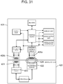
- FIG. 31 is a block configuration diagram of a conventional non-contact power receiving appliance and a conventional non-contact power supplying appliance described in Patent Literature 1.
- appliance body 420 corresponds to a non-contact power supplying appliance
- remote control device 401 corresponds to a non-contact power receiving appliance.
- Remote control device 401 includes power-receiving resonance circuit 405a and communication resonance circuit 405b.
- Resonance circuit 405a is used to wirelessly receive power transmitted from appliance body 420, based on a change in a magnetic flux generated from appliance body 420, to input an instruction to appliance body 420 and output information concerning appliance body 420.
- Resonance circuit 405b is used to wirelessly carry out bidirectional communication of a communication signal with appliance body 420.
- Appliance body 420 includes power-supplying resonance circuit 422 corresponding to resonance circuit 405a, communication resonance circuit 421 corresponding to resonance circuit 405b, and communication circuit 423.
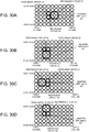
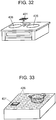
- FIG. 32, FIG. 33 are diagrams showing a concrete example of a non-contact power supplying appliance according to the conventional technique.
- the example shown in FIG. 32 is an inductive heating device in which two heating coils 426 are disposed spaced apart.
- the example shown in FIG. 33 is an inductive heating device in which many relatively small heating coils 426 are closely arranged in a matrix shape.
- FIG. 34 is a flowchart showing control for a non-contact power supplying appliance to detect remote control device 401 in the conventional technique.
- FIG. 35 is a block configuration diagram of a conventional non-contact power receiving appliance and a conventional non-contact power supplying appliance described in Non-Patent Literature 1.
- Non-Patent Literature 1 prescribes specifications of a non-contact power transmitting system mainly for smartphones and mobile devices.
- the non-contact power transmitting system prescribed in Non-Patent Literature 1 includes base station 501 and mobile device 502.
- base station 501 controls a magnitude of the transmitted power, in accordance with a magnitude of requested power transmitted from power receiver 505 of mobile device 502 to power transmitter 504 of base station 501 via communication control unit 508.
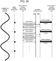
- FIG. 36 is a state transition diagram of a conventional wireless charging system described in Non-Patent Literature 1.
- the wireless charging system detects whether mobile device 502 is placed on base station 501.
- base station 501 detects placement of mobile device 502 by detecting a change in impedance. Upon detecting the placement of mobile device 502, base station 501 transits to ping state 602.
- base station 501 transmits micro power for operating communication control unit 508c, from power conversion unit 506 to power pick-up unit 507 of mobile device 502.
- base station 501 when a response from mobile device 502 is not sent to base station 501 within a predetermined period via communication control unit 508, base station 501 returns to selection state 601. When the response is sent, base station 501 continues transmission of the micro power, and transits to identification state/setting state 603.
- mobile device 502 sends identification information and a magnitude of the requested power to base station 501 via communication control unit 508.
- base station 501 determines it is adaptable to the magnitude of the requested power from mobile device 502, base station 501 completes the setting and transits to power supply state 604.
- power transmission is carried out from power transmitter 504 of base station 501 to power receiver 505 of mobile device 502.
- the magnitude of transmitted power is controlled in accordance with the magnitude of the requested power transmitted from power receiver 505 of mobile device 502 to power transmitter 504 of base station 501.
- the transmitted power is consumed by load 509 of mobile device 502.
- FIG. 37 shows a format of a communication packet used in the wireless charging system described in Non-Patent Literature 1.
- the format of the communication packet includes preamble 701, header 702, message 703, and checksum 704.
- Preamble 701 is data from 11 bytes to 25 bytes for detecting a communication packet.
- Header 702 is data of 1 byte to which a code corresponding to a type and a size of a message is allocated.
- Message 703 is data from 1 byte to 27 bytes corresponding to a code of header 702.
- Checksum 704 is data of 1 byte for detecting a packet error.
- FIG. 38 is a diagram showing a relationship between a message size and a code of a header prescribed in Non-Patent Literature 1.
- FIG. 39 is a diagram showing a message type prescribed in Non-Patent Literature 1.
- Non-Patent Literature 1 prescribes to use a message size from 1 byte to 27 bytes obtained by substituting a code within header 702 into an equation shown in FIG. 38 .
- a packet type of a message and a message size corresponding to each code are prescribed. However, a detailed description will be omitted here.
- US 2015/0054347 A1 discloses a power transmitting apparatus that comprises a plurality of coils configured to wirelessly transmit power.
- the power transmitting apparatus receives information representing receiving performance from a power receiving apparatus, and, based on the information representing the receiving performance, assigns output values to a first coil and a second coil out of the plurality of coils such that the first coil and the second coil have different transmission power amounts.
- WO 2014/195143 A1 discloses a power transmitter that is arranged to transfer power to a power receiver via a wireless inductive power transfer signal transmitted from a transmit coil to a power receiver.
- a first communication unit communicates a message to the power receiver on a first communication link.
- a second communication unit receives data from the power receiver on a separate second communication link having a longer range.
- the power receiver comprises a third communication unit which receives the first message.
- a response generator generates a response message to the message and a fourth communication unit transmits the response message to the power transmitter over the second communication link.
- the power transmitter determines an expected response message to the message and a power controller controls the power level of the power transfer signal dependent on whether a message is received on the second communication link corresponding to the expected response message.
- WO 2014/204158 A1 discloses a wireless power transmission method, a wireless power transmission apparatus, and a wireless charging system in a wireless power transmission field, and there is provided a communication method of a wireless power transmitter capable of the transmission of power in a wireless manner, and the communication method may include receiving communication information indicating whether or not a second communication mode is available using a first communication mode from a wireless power receiver, determining whether or not communication in a second communication mode is available using the communication information, notifying either one of the first communication mode and second communication mode to the wireless power receiver based on the determination result, and performing communication with the wireless power receiver using a communication mode notified to the wireless power receiver.
- NPL1 System Description Wireless Power Transfer Volume I: Low Power Part 1: Interface Definition Version 1. 1. 2 June 2013
- a prior art described in PTL1 is configured to switch between transmitting only large power from a power supply coil disposed in the appliance body and transmitting micro power and communication data, in accordance with a selection of a cooking container like a pot or a selection of a remote control device including a weak electric circuit like a communication circuit and an information input-output circuit. Therefore, the power supply coil can be shared with a communication coil.
- Non-Patent Literature 1 because the transmitted power is limited to 5 W or less, communication by superimposing data on the transmitted power is easy. Therefore, the power supply coil and the communication coil can be shared by both a power supply side and a power receiving side, and power supply and data communication can be always carried out simultaneously.
- An object of the present disclosure is to provide a non-contact power transmitting system for solving conventional problems, capable of carrying out high-precision communication and safe power transmission without being affected by noise and having a practical scale.
- the non-contact power transmitting system of the present disclosure includes a non-contact power supplying appliance and a non-contact power receiving appliance as described below.
- the non-contact power supplying appliance includes a plurality of power supply units that transmit power, a power-supply side communication unit that sends and receives a communication packet, and a power-supply side controller that controls the power supply units and the power-supply side communication unit, to contactlessly transmit power to the non-contact power receiving appliance.
- the power-supply side communication unit sends a response-request message for placement detection of the non-contact power receiving appliance, and thereafter receives a corresponding response message, so that the power-supply side communication unit completes the placement detection of the non-contact power receiving appliance.
- the power-supply side communication unit sends a response-request message for identifying a placement location of the non-contact power receiving appliance, and thereafter receives a corresponding response message, so that the power-supply side controller identifies a combination of the non-contact power receiving appliance and some of the power supply units.
- the power-supply side controller controls the power supply units, in accordance with a corresponding response message received by the power-supply side communication unit.
- the non-contact power receiving appliance includes a power receiving unit that receives power, a power-receiving side communication unit that sends and receives a communication packet, and a power measuring unit that measures power under reception by the power receiving unit, to receive power contactlessly transmitted from the non-contact power supplying appliance.
- the power-receiving side communication unit upon receiving a response-request message for placement detection of the non-contact power receiving appliance, sends a corresponding response message.
- the power-receiving side communication unit Upon receiving a response-request message for identifying a placement location of the non-contact power receiving appliance, the power-receiving side communication unit sends a corresponding response message.
- the power-receiving side communication unit Upon receiving a response-request message for controlling power transmitted, the power-receiving side communication unit sends a magnitude of the power measured by the power measuring unit, as a response message.
- a non-contact power supplying appliance includes a plurality of power supply units that transmit power, a power-supply side communication unit that sends and receives a communication packet, and a power-supply side controller that controls the power supply units and the power-supply side communication unit, to contactlessly transmit power to a non-contact power receiving appliance.
- the power-supply side communication unit sends a response-request message for placement detection of the non-contact power receiving appliance, and thereafter receives a corresponding response message, so that the power-supply side communication unit completes the placement detection of the non-contact power receiving appliance.
- the power-supply side communication unit sends a response-request message for identifying a placement location of the non-contact power receiving appliance, and thereafter receives a corresponding response message, so that the power-supply side controller identifies a combination of the non-contact power receiving appliance and some of the power supply units.
- the power-supply side controller controls the power supply unit, in accordance with a corresponding response message received by the power-supply side communication unit.
- the non-contact power supplying appliance of a practical scale capable of carrying out high-precision communication and safe power transmission.
- the non-contact power supplying appliance further includes, in addition to the first aspect, a storage unit that is controlled by the power-supply side controller and stores information communicated via the power-supply side communication unit.
- the power supply units are arranged in a matrix shape.
- the power-supply side controller executes the following process (A) to process (F) by controlling the power supply units, the power-supply side communication unit, and the storage unit.
- the non-contact power supplying appliance is an induction heating cooker having a plurality of power supply units arranged in a matrix shape
- a combination of the non-contact power receiving appliance and some of the power supply units can be identified.
- the power-supply side controller excludes the non-contact power receiving appliance to which power is supplied, from power transmission targets, when the power-supply side communication unit does not receive a fourth response message during a predetermined period from the non-contact power receiving appliance that is receiving power after the power-supply side communication unit sends a fourth response-request message to the non-contact power receiving appliance that is receiving the power.
- the power transmission is stopped. Therefore, safety of the non-contact power transmitting system can be improved.
- the power-supply side controller executes placement detection after excluding the non-contact power receiving appliance that is receiving the power, from the power transmission targets.
- response speed can be improved as well as power consumption can be reduced.
- the non-contact power receiving appliance excluded from the power transmission targets is registered again as the power transmission target, when the non-contact power receiving appliance is placed again.
- a non-contact power receiving appliance includes a power receiving unit that receives power, a power-receiving side communication unit that sends and receives a communication packet, and a power measuring unit that measures the power under reception by the power receiving unit, to receive the power contactlessly transmitted from the non-contact power supplying appliance.
- the power-receiving side communication unit upon receiving a response-request message for placement detection of the non-contact power receiving appliance, sends a corresponding response message.
- the power-receiving side communication unit upon receiving a response-request message for identifying a placement location of the non-contact power receiving appliance, sends a corresponding response message.
- the power-receiving side communication unit Upon receiving a response-request message for controlling power transmitted, the power-receiving side communication unit sends a magnitude of the power measured by the power measuring unit, as a response message.
- the non-contact power receiving appliance of a practical scale capable of carrying out high-precision communication and safe power transmission.
- the non-contact power receiving appliance further includes, in addition to the sixth aspect, a load, and a switching unit that is closed when the non-contact power receiving appliance is placed, is opened when the power transmitted from the non-contact power supplying appliance is supplied to the load and the non-contact power receiving appliance is lifted, and stops the supply of the power to the load.
- the power-receiving side communication unit sends a response message indicating moving of the non-contact power receiving appliance, when the switching unit is opened.
- the non-contact power supplying appliance can easily detect the movement of the non-contact power receiving appliance that is receiving power.
- a non-contact power transmitting system includes the non-contact power supplying appliance of the first aspect and the non-contact power receiving appliance of the sixth aspect. According to the present aspect, it is possible to provide the power transmitting system of a practical scale capable of carrying out high-precision communication and safe power transmission.
- the non-contact power transmitting system further includes, in addition to the eighth aspect, an adapter appliance that receives power from the non-contact power supplying appliance and transmits power to the non-contact power receiving appliance, and sends and receives a communication packet between the non-contact power supplying appliance and the non-contact power receiving appliance.
- the power-receiving side communication unit is a power-receiving communication unit that receives power which is load-modulated to send and receive a communication packet.
- the non-contact power supplying appliance further includes a zero-cross detector that detects a zero-cross point of a commercial power source, and the power-supply side communication unit is configured to send a timing of the zero-cross point to the adapter appliance.
- the adapter appliance includes a power-supply communication unit that contactlessly transmits power to a power-receiving communication unit and sends and receives a communication packet to and from the power-receiving communication unit, and an adapter-side communication unit that communicates with the power-supply side communication unit.
- the power-supply side communication unit sends a zero-cross point timing to the adapter-side communication unit, and the power-supply communication unit transmits power and sends and receives a communication packet in accordance with the zero-cross point.
- the power-supply side controller is configured to control, for power control, the power supply units in accordance with a communication packet received by the power-supply side communication unit.
- the present aspect it is possible to provide the power transmitting system of a practical scale capable of carrying out high-precision communication and safe power transmission.
- a non-contact power transmitting system further includes, in addition to the ninth aspect, an adapter-side power receiving unit that receives the power transmitted from the non-contact power supplying appliance.
- the power-supply side controller is configured to identify a combination of the adapter-side power receiving unit and some of the power supply units, to identify a placement location of the non-contact power receiving appliance.
- FIG. 1 to FIG. 25B A first exemplary embodiment of the present disclosure will be described with reference to FIG. 1 to FIG. 25B .
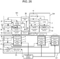
- FIG. 1 is a block configuration diagram of a non-contact power transmitting system according to the present exemplary embodiment.
- the non-contact power transmitting system according to the present exemplary embodiment includes non-contact power supplying appliance 100 and non-contact power receiving appliance 200.
- Non-contact power supplying appliance 100 has a plurality of power supply units 1, controller 2, communication unit 5, and storage unit 6.
- Communication unit 5 is a power-supply side communication unit.
- Communication unit 5 communicates with communication units 10 of non-contact power receiving appliances 200 described later.
- Storage unit 6 stores appliance information concerning non-contact power receiving appliances 200 sent from communication unit 10 via communication unit 5.
- Power supply unit 1 has high-frequency power source unit 3 and resonance circuit 4.
- High-frequency power source unit 3 converts power supplied from a commercial power source into high-frequency power.
- Resonance circuit 4 contactlessly transmits power converted by high-frequency power source unit 3 to resonance circuit 8 of non-contact power receiving appliance 200 described later.
- Controller 2 is a power-supply side controller. Based on the above information stored in storage unit 6, controller 2 individually controls each of power supply units 1, and controls power contactlessly transmitted from resonance circuit 4 of power supply unit 1 to resonance circuit 8 that is included in each non-contact power receiving appliance 200.
- Non-contact power receiving appliance 200 has load 7, resonance circuit 8, power source circuit 9, communication unit 10, controller 11, and power measuring unit 12.
- Resonance circuit 8 is a power receiving unit of non-contact power receiving appliance 200 that receives transmitted power.
- Power source circuit 9 converts the power received by resonance circuit 8, into power for operating load 7.
- Communication unit 10 is a power-receiving side communication unit that communicates with communication unit 5 of non-contact power supplying appliance 100.
- Controller 11 is a controller on a power receiving side. Controller 11 calculates a difference (hereinafter, referred to as a "power error") between a magnitude of the power under reception measured by power measuring unit 12 and rated power of load 7, in order to control power supplied to load 7.
- a power error a difference between a magnitude of the power under reception measured by power measuring unit 12 and rated power of load 7, in order to control power supplied to load 7.
- Load 7 is a motor mounted on a juicer, a blender, or the like, or a heater mounted on a thermos, or the like, for example.
- Non-contact power supplying appliance 100 has a configuration having a plurality of power supply units embedded in a countertop of a kitchen, such as an induction heating cooker, for example.
- FIG. 2 a format of a communication packet used for communication between non-contact power supplying appliance 100 and non-contact power receiving appliance 200.
- FIG. 2 shows a frame format of a communication packet.
- format 13 of a communication packet includes preamble 13a, sender address 13b, destination address 13c, header 13d, message 13e, and checksum 13f.
- Preamble 13a is used to detect a communication packet. Codes corresponding to a type and a size of a message are allocated to header 13d. Appliance information corresponding to the code allocated to header 13d is stored in message 13e. Checksum 13f is used to detect a packet error.
- the communication packet has preamble 13a of 11 bytes to 25 bytes, sender address 13b of 1 byte, destination address 13c of 1 byte, header 13d of 1 byte, message 13e of 1 byte to 27 bytes, and checksum 13f of 1 byte.
- a size of message 13e is determined in accordance with a code of header 13d.
- Optimum values of sizes of these data change in accordance with a property of a physical layer and application to be realized, and are not limited to the above values.
- Non-contact power supplying appliance 100 is an induction heating cooker having a plurality of power supply units 1 arranged in a matrix shape.
- FIG. 3 shows state transition of the non-contact power transmitting system of the present exemplary embodiment.
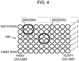
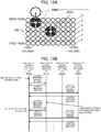
- FIG. 4 is a plan view schematically showing a situation that non-contact power receiving appliances 200a, 200b are placed on non-contact power supplying appliance 100.
- the non-contact power transmitting system of the present exemplary embodiment has initial registration state 14, placement detection state 15, scan processing state 16, registration state 17, and power supply state 18.
- non-contact power supplying appliance 100 has a plurality of power supply units 1 arranged in a matrix shape of n rows in a vertical direction and m columns in a lateral direction. Specifically, n is 6, and m is 10, and 60 power supply units in total are arranged in a matrix shape.
- Resonance circuits 8 of non-contact power receiving appliances 200 (200a, 200b) have a size of covering four power supply units 1.
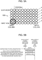
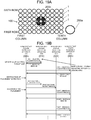
- FIG. 5A is a plan view schematically showing a state that non-contact power receiving appliance 200 (200c) is placed at an initial registration position on non-contact power supplying appliance 100.
- FIG. 5B is a diagram showing a communication sequence between non-contact power supplying appliance 100 and non-contact power receiving appliance 200c in initial registration.
- a j-th row means a j-th row from the front
- a k-th column means a k-th column from the left.
- j is a natural number equal to or smaller than n
- k is a natural number equal to or smaller than m.
- a user of or a person who places non-contact power supplying appliance 100 instructs initial registration to non-contact power supplying appliance 100, after placing newly purchased non-contact power receiving appliance 200 at an initial registration position.
- the initial registration position is a position that corresponds to four power supply units 1 arranged in the first column and the second column of the first row and the second row.
- the instruction of the initial registration means pressing a start key of the initial registration disposed on an operation panel (not shown) of non-contact power supplying appliance 100, for example.
- non-contact power supplying appliance 100 has a predetermined communication address (00h). Because non-contact power receiving appliance 200 has a communication address allocated at the time of being registered in non-contact power supplying appliance 100, an individual communication address is not set in non-contact power receiving appliance 200 before initial registration. Therefore, FIG. 5B shows a case of using (FFh) as a communication address of non-contact power receiving appliance 200.
- controller 2 when controller 2 receives an instruction for initial registration, controller 2 controls four power supply units 1 for initial registration to transmit power necessary for communication unit 10 to operate.
- controller 2 controls communication unit 5 so as to send a communication packet that stores communication address (00h) of the non-contact power supplying appliance in sender address 13b, stores communication address (FFh) of non-contact power receiving appliance 200 for initial registration in destination address 13c, and stores a code meaning the initial registration in header 13d.
- controller 11 of non-contact power receiving appliance 200 controls communication unit 10 to send the communication packet.
- communication address (FFh) of non-contact power receiving appliance 200 for initial registration that is, the self, in sender address 13b
- communication address (00h) of non-contact power supplying appliance 100 in destination address 13c a code indicating storing of the appliance information of non-contact power receiving appliance 200 in message 13e, in header 13d.
- the appliance information stored in message 13e includes appliance ID 19 that is set for each power receiving appliance, rated power of load 7, and a diameter of a coil included in resonance circuit 8.
- controller 2 compares appliance ID 19 included in the communication packet with each of appliance IDs 19 of non-contact power receiving appliances 200 which have been initially registered, respectively.
- controller 2 controls communication unit 5 so as to send a communication packet that stores the communication address information of initially registered non-contact power receiving appliance 200 in message 13e, to non-contact power receiving appliance 200 which is to be initially registered, and ends the initial registration.
- controller 2 controls communication unit 5 so as to send a communication packet that stores a new communication address in message 13e, to non-contact power receiving appliance 200 which is to be initially registered, and ends the initial registration. Thereafter, non-contact power receiving appliance 200 recognizes that the communication address sent from non-contact power supplying appliance 100 is for exclusive use of the self, and sends and receives a communication packet by using this communication address.
- FIG. 5A and FIG. 5B suggests that at least three non-contact power receiving appliances 200 exist. That is, this example indicates a case where non-contact power supplying appliance 100 carries out initial registration of non-contact power receiving appliance 200c in a situation that communication address (Olh) and communication address (02h) are allocated to non-contact power receiving appliance 200a and non-contact power receiving appliance 200b.
- communication address (Olh) and communication address (02h) are allocated to non-contact power receiving appliance 200a and non-contact power receiving appliance 200b.
- controller 2 controls power supply unit 1 provided at the initial registration position to transmit power necessary to operate communication unit 10 of non-contact power receiving appliance 200c. Further, controller 2 controls communication unit 5 so as to send a communication packet for initial registration to communication unit 10 of non-contact power receiving appliance 200c.
- controller 11 controls communication unit 10 to send a communication packet storing appliance information.
- controller 2 compares appliance ID 19 included in the sent communication packet with appliance ID 19 stored in storage unit 6 and appliance ID 19 of non-contact power receiving appliance 200b.
- controller 2 sends a communication packet that stores, in message 13e, communication address (Olh) of non-contact power receiving appliance 200a or communication address (02h) of non-contact power receiving appliance 200b, to non-contact power receiving appliance 200c, and ends the initial registration.
- controller 2 sends a communication packet that stores, in message 13e, newly allocated communication address (03h) allocated to non-contact power receiving appliance 200c, to non-contact power receiving appliance 200c, and ends the initial registration.
- non-contact power receiving appliance 200c uses communication address (03h) sent from non-contact power supplying appliance 100 as a sender address and as a destination address of the self, and sends and receives a communication packet to and from non-contact power supplying appliance 100.
- non-contact power receiving appliance 200 is newly purchased and the user or the person who places non-contact power receiving appliance 200 carries out initial registration of non-contact power receiving appliance 200.
- work of initial registration can be omitted by registering in advance non-contact power receiving appliance 200 in non-contact power supplying appliance 100 in a manufacturing process.
- Appliance ID 19 of non-contact power receiving appliance 200 may be prescribed by combining maker codes allocated to makers by a standard organization and codes own to the makers, for example.
- placement detection state 15 of a non-contact power transmitting system according to the present exemplary embodiment will be described with reference to FIG. 6A, FIG. 6B .
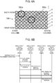
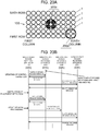
- FIG. 6A is a plan view schematically showing a state that non-contact power receiving appliances 200a, 200c are placed on non-contact power supplying appliance 100.
- FIG. 6B is a diagram showing a communication sequence between a non-contact power supplying appliance and a non-contact power receiving appliance in placement detection of a non-contact power receiving appliance.
- non-contact power receiving appliances 200a, 200b, 200c three non-contact power receiving appliances (non-contact power receiving appliances 200a, 200b, 200c) are already initially registered, and non-contact power supplying appliance 100 executes placement detection in a situation that two of the non-contact power receiving appliances (non-contact power receiving appliances 200a, 200c) are placed on non-contact power supplying appliance 100.
- Instruction of placement detection in the communication sequence shown in FIG. 6B is executed by the user pressing a start key of placement detection provided in non-contact power supplying appliance 100.
- Non-contact power supplying appliance 100 may periodically automatically detect whether non-contact power receiving appliance 200 is placed.
- controller 2 controls all of power supply units 1 so as to supply power necessary to operate communication units 10 of non-contact power receiving appliances 200a to 200c.
- controller 2 controls communication unit 5 so as to send a communication packet that stores a first response-request message for placement detection, to non-contact power receiving appliances 200a, 200b, 200c.
- controller 11 controls communication unit 10 to send a communication packet that stores a magnitude of the power measured by power measuring unit 12 as a first response message corresponding to the first response-request message.
- controller 2 Upon receiving the communication packet sent from non-contact power receiving appliance 200a, controller 2 stores in storage unit 6, communication address (Olh) of non-contact power receiving appliance 200a and a magnitude of the power under reception. Upon further receiving the communication packet sent from non-contact power receiving appliance 200c, controller 2 stores in storage unit 6, communication address (03h) of non-contact power receiving appliance 200c and a magnitude of the power under reception.
- Non-contact power supplying appliance 100 ends placement detection in placement detection state 15, and transits to scan processing state 16, in order to identify placement locations of non-contact power receiving appliances 200a, 200c.
- controller 2 determines the numbers of rows and columns to which scan processing is to be simultaneously executed, based on appliance information of non-contact power receiving appliance 200 detected in placement detection state 15, out of appliance information of non-contact power receiving appliance 200 stored in storage unit 6.
- controller 2 simultaneously carries out scan processing to power supply units 1 disposed in adjacent two rows or two columns.
- j, k described later are 2.
- controller 2 controls power supply unit 1 disposed in the first row to j-th row so as to supply power necessary to operate communication unit 10 of detected non-contact power receiving appliance 200. Controller 2 further controls communication unit 5 so as to send a second response-request message for identifying a placement location, to detected non-contact power receiving appliance 200.
- detected non-contact power receiving appliance 200 When detected non-contact power receiving appliance 200 is placed above power supply unit 1 disposed in the first row to j-th row, detected non-contact power receiving appliance 200 receives a second response-request message, and sends a magnitude of the power under reception to non-contact power supplying appliance 100 as a second response message corresponding to the second response-request message.
- power supply unit 1 which is disposed in the j-th row will be expressed as j-th row power supply unit 1
- that non-contact power receiving appliance 200 is placed above power supply unit 1 which is disposed in the j-th row will be expressed as non-contact power receiving appliance 200 is placed on the j-th row.
- this non-contact power receiving appliance When detected non-contact power receiving appliance 200 is not placed on the first row to j-th row, this non-contact power receiving appliance does not receive a second response-request message, and therefore, does not send a second response message.
- controller 2 stores in storage unit 6, a communication address of non-contact power receiving appliance 200 which sends the second response message stored in the second response message and a magnitude of the power under reception.
- controller 2 executes process (A) and process (B) of the scan processing to all rows by shifting each one row, and identifies a row in which a magnitude of the power received by non-contact power receiving appliance 200 that sends the second response message becomes the largest.
- controller 2 can identify presence or absence of sending of a second response message from detected non-contact power receiving appliance 200, and can identify a row on which detected non-contact power receiving appliance 200 is placed, from a magnitude of the power under reception of non-contact power receiving appliance 200 that sends the second response message.
- controller 2 controls power supply units 1 disposed in the first row to k-th row so as to supply power necessary to operate communication unit 10 of detected non-contact power receiving appliance 200. Controller 2 further controls communication unit 5 so as to send a third response-request message for identifying a placement location, to detected non-contact power receiving appliance 200.
- this non-contact power receiving appliance When detected non-contact power receiving appliance 200 is disposed on the first column to k-th column, this non-contact power receiving appliance receives a third response-request message sent from non-contact power supplying appliance 100, and sends a magnitude of the power under reception to non-contact power supplying appliance 100 as a third response message corresponding to the third response-request message.
- this non-contact power receiving appliance When detected non-contact power receiving appliance 200 is not placed on the first column to k-th column, this non-contact power receiving appliance does not receive a third response-request message, and therefore, does not send a third response message.
- controller 2 stores in storage unit 6, a communication address of non-contact power receiving appliance 200 which sends the third response message and a magnitude of the power under reception.
- controller 2 executes process (D) and process (E) of the scan processing to all columns by shifting each one column, and identifies a column in which a magnitude of the power received by non-contact power receiving appliance 200 that sends the third response message becomes the largest.
- controller 2 can identify presence or absence of sending of a third response message from detected non-contact power receiving appliance 200, and can identify a column on which detected non-contact power receiving appliance 200 is placed, from a magnitude of the power under reception by non-contact power receiving appliance 200 that sends the third response message.
- Controller 2 identifies a combination of detected non-contact power receiving appliance 200 and some of power supply units 1, from the row identified by process (C) of the scan processing and the column identified by process (F) of the scan processing.
- Scan processing state 16 will be concretely described with reference to FIG. 7A to FIG. 16B .
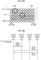
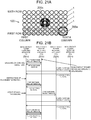
- FIG. 7A is a plan view schematically showing a situation of scan processing applied to the first row and the second row.
- FIG. 7B is a diagram showing a communication sequence between a non-contact power supplying appliance and non-contact power receiving appliances in the situation shown in FIG. 7A .
- controller 2 recognizes that non-contact power receiving appliances 200a, 200c are placed on non-contact power supplying appliance 100.
- controller 2 first determines the numbers of rows and columns to which scan processing is to be simultaneously executed, in accordance with appliance information of non-contact power receiving appliances 200a, 200c that are stored in storage unit 6, particularly, in accordance with a diameter of a coil included in each resonance circuit 8.
- a diameter of each resonance circuit 8 of non-contact power receiving appliances 200a, 200c is assumed to be in a size for two power supply units 1.
- Controller 2 sets 2 as the numbers of rows and columns to which scan processing is to be executed simultaneously.
- controller 2 controls power supply units 1 meshed in a grey color in the first row and the second row so as to supply power necessary to operate communication units 10 of non-contact power receiving appliances 200a, 200c.
- controller 2 further controls communication unit 5 so as to send a communication packet that stores a second response-request message, to communication address (Olh) of non-contact power receiving appliance 200a and communication address (03h) of non-contact power receiving appliance 200c.
- non-contact power receiving appliances 200a, 200c are not placed on the first row and the second row, non-contact power receiving appliances 200a, 200c cannot receive power, do not receive a second response-request message, and do not send a second response message.
- FIG. 8A is a plan view schematically showing a situation of scan processing applied to the second row and the third row.
- FIG. 8B is a diagram showing a communication sequence between a non-contact power supplying appliance and non-contact power receiving appliances in the situation shown in FIG. 8A .
- controller 2 controls power supply units 1 meshed in a grey color in the second row and the third row so as to supply power necessary to operate each communication unit 10 of non-contact power receiving appliances 200a, 200c.
- controller 2 further controls communication unit 5 so as to send a communication packet that stores a second response-request message, to communication address (Olh) of non-contact power receiving appliance 200a and communication address (03h) of non-contact power receiving appliance 200c.
- non-contact power receiving appliance 200c Because non-contact power receiving appliance 200c is placed on the third row and the fourth row, communication unit 10 of non-contact power receiving appliance 200c receives power transmitted from power supply unit 1 of the third row, and receives a second response message sent from communication unit 5.
- non-contact power receiving appliance 200a because non-contact power receiving appliance 200a is placed neither on the second row nor on the third row, non-contact power receiving appliance 200a cannot receive power, does not receive a second response-request message, and does not send a second response message.
- controller 11 controls communication unit 10 to send a magnitude of the power detected by power measuring unit 12 as a second response message.
- controller 2 stores in storage unit 6, communication address (03h) of non-contact power receiving appliance 200c and a magnitude of the power under reception.
- FIG. 9A is a plan view schematically showing a situation of scan processing applied to the third row and the fourth row.
- FIG. 9B is a diagram showing a communication sequence between a non-contact power supplying appliance and non-contact power receiving appliances in the situation shown in FIG. 9A .
- controller 2 controls power supply units 1 meshed in a grey color in the third row and the fourth row so as to supply power necessary to operate each communication unit 10 of non-contact power receiving appliances 200a, 200c.
- controller 2 further controls communication unit 5 so as to send a communication packet that stores a second response-request message, to communication address (Olh) of non-contact power receiving appliance 200a and communication address (03h) of non-contact power receiving appliance 200c.
- non-contact power receiving appliance 200c Because non-contact power receiving appliance 200c is placed on the third row and the fourth row, communication unit 10 of non-contact power receiving appliance 200c receives power transmitted from power supply units 1 of the third row and the fourth row, and receives a second response-request message sent from communication unit 5.
- non-contact power receiving appliance 200a because non-contact power receiving appliance 200a is placed neither on the third row nor on the fourth row, non-contact power receiving appliance 200a cannot receive power, does not receive a second response-request message, and does not send a second response message.
- controller 11 controls communication unit 10 to send a magnitude of the power detected by power measuring unit 12, as a second response message.
- controller 2 stores in storage unit 6, communication address (03h) of non-contact power receiving appliance 200c and a magnitude of the power under reception.
- controller 2 can identify a row in which a magnitude of the power received by non-contact power receiving appliance 200c becomes largest, and can recognize that non-contact power receiving appliance 200c is placed on the third row and the fourth row.
- FIG. 10A is a plan view schematically showing a situation of scan processing applied to the fourth row and the fifth row.
- FIG. 10B is a diagram showing a communication sequence between a non-contact power supplying appliance and non-contact power receiving appliances in the situation shown in FIG. 10A .
- controller 2 controls power supply units 1 meshed in a grey color in the fourth row and the fifth row so as to supply power necessary to operate communication units 10 of non-contact power receiving appliances 200a, 200c.
- controller 2 further controls communication unit 5 so as to send a communication packet that stores a second response-request message, to communication address (Olh) of non-contact power receiving appliance 200a and communication address (03h) of non-contact power receiving appliance 200c.
- non-contact power receiving appliance 200a Because non-contact power receiving appliance 200a is placed on the fifth row and the sixth row, communication unit 10 of non-contact power receiving appliance 200a receives the power transmitted from power supply unit 1 of the fifth row, and receives a second response message sent from communication unit 5.
- non-contact power receiving appliance 200c because non-contact power receiving appliance 200c is placed on the third row and the fourth row, communication unit 10 of non-contact power receiving appliance 200c receives the power transmitted from power supply unit 1 of the fourth row, and receives a second response message sent from communication unit 5.
- controller 11 controls communication unit 10 to send a magnitude of the power detected by power measuring unit 12 to non-contact power supplying appliance 100 as a second response message.
- controller 2 stores in storage unit 6, communication address (Olh) of non-contact power receiving appliance 200a, a magnitude of the power under reception, communication address (03h) of non-contact power receiving appliance 200c and a magnitude of the power under reception.
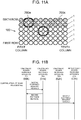
- FIG. 11A is a plan view schematically showing a situation of scan processing applied to the fifth row and the sixth row.
- FIG. 11B is a diagram showing a communication sequence between a non-contact power supplying appliance and non-contact power receiving appliances in the situation shown in FIG. 11A .
- controller 2 controls power supply units 1 meshed in a grey color in the fifth row and the sixth row so as to supply power necessary to operate each communication unit 10 of non-contact power receiving appliances 200a, 200c.
- controller 2 further controls communication unit 5 so as to send a communication packet that stores a second response-request message, to communication address (Olh) of non-contact power receiving appliance 200a and communication address (03h) of non-contact power receiving appliance 200c.
- non-contact power receiving appliance 200a Because non-contact power receiving appliance 200a is placed on the fifth row and the sixth row, communication unit 10 of non-contact power receiving appliance 200a receives power transmitted from power supply units 1 of the fifth row and the sixth row, and receives a second response message sent from communication unit 5.
- non-contact power receiving appliance 200c because non-contact power receiving appliance 200c is placed neither on the fifth row nor on the sixth row, non-contact power receiving appliance 200c cannot receive power, does not receive a second response-request message, and does not send a second response message.
- controller 11 controls communication unit 10 to send a magnitude of the power detected by power measuring unit 12, as a second response message.
- controller 2 stores in storage unit 6, communication address (Olh) of non-contact power receiving appliance 200a and a magnitude of the power under reception.
- controller 2 can identify a row in which a magnitude of the power received by non-contact power receiving appliance 200a becomes largest, and can recognize that non-contact power receiving appliance 200a is placed on the fifth row and the sixth row.
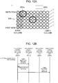
- FIG. 12A is a plan view schematically showing a situation of scan processing applied to the first column and the second column.
- FIG. 12B is a diagram showing a communication sequence between a non-contact power supplying appliance and non-contact power receiving appliances in the situation shown in FIG. 12A .
- controller 2 controls power supply units 1 meshed in a grey color in the first column and the second column so as to supply power necessary to operate each communication unit 10 of non-contact power receiving appliances 200a, 200c.
- controller 2 further sends a communication packet that stores a third response-request message, to communication address (Olh) of non-contact power receiving appliance 200a and communication address (03h) of non-contact power receiving appliance 200c.
- non-contact power receiving appliance 200a Because non-contact power receiving appliance 200a is placed on the second column and the third column, communication unit 10 of non-contact power receiving appliance 200a receives power transmitted from power supply unit 1 of the second column, and receives a third response message sent from communication unit 5.
- non-contact power receiving appliance 200c because non-contact power receiving appliance 200c is placed neither on the first column nor on the second column, non-contact power receiving appliance 200c cannot receive power, does not receive a third response-request message, and does not send a third response message.
- controller 2 may not supply power to power supply unit 1 on a row on which non-contact power receiving appliance 200 is not placed. Accordingly, energy saving performance of non-contact power supplying appliance 100 can be improved.
- controller 2 may not supply power to power supply units 1 of the first row and the second row out of power supply units 1 meshed in a grey color in the first column and the second column.
- controller 11 controls communication unit 10 to send a magnitude of the power detected by power measuring unit 12 as a third response message.
- controller 2 stores in storage unit 6, communication address (Olh) of non-contact power receiving appliance 200a and a magnitude of the power under reception.
- FIG. 13A is a plan view schematically showing a situation of scan processing applied to the second column and the third column.
- FIG. 13B is a diagram showing a communication sequence between a non-contact power supplying appliance and non-contact power receiving appliances in the situation shown in FIG. 13A .
- controller 2 controls power supply units 1 meshed in a grey color in the second column and the third column so as to supply power necessary to operate each communication unit 10 of non-contact power receiving appliances 200a, 200c.
- controller 2 further sends a communication packet that stores a third response-request message, to communication address (Olh) of non-contact power receiving appliance 200a and communication address (03h) of non-contact power receiving appliance 200c.
- non-contact power receiving appliance 200a Because non-contact power receiving appliance 200a is placed on the second column and the third column, communication unit 10 of non-contact power receiving appliance 200a receives the power transmitted from power supply units 1 of the second column and the third column, and receives a third response-request message sent from communication unit 5.
- non-contact power receiving appliance 200c because non-contact power receiving appliance 200c is placed neither on the second column nor on the third column, non-contact power receiving appliance 200c cannot receive power, does not receive a third response-request message, and does not send a third response message.
- controller 11 controls communication unit 10 to send a magnitude of the power detected by power measuring unit 12, as a third response message.
- controller 2 stores in storage unit 6, communication address (Olh) of non-contact power receiving appliance 200a and a magnitude of the power under reception.
- controller 2 can identify a row in which a magnitude of the power received by non-contact power receiving appliance 200a becomes largest, and can recognize that non-contact power receiving appliance 200a is placed on the second column and the third column.
- controller 2 understands that non-contact power receiving appliance 200a is placed on the second column, the third column of the fifth row, sixth row, and stores a combination of non-contact power receiving appliance 200a and some of power supply units 1, in storage unit 6.
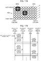
- FIG. 14A is a plan view schematically showing a situation of scan processing applied to the third column and the fourth column.
- FIG. 14B is a diagram showing a communication sequence between a non-contact power supplying appliance and non-contact power receiving appliances in the situation shown in FIG. 14A .
- controller 2 controls power supply units 1 meshed in a grey color in the third column and the fourth column so as to supply power necessary to operate communication unit 10 of non-contact power receiving appliance 200c of which a placement location is not identified.
- controller 2 further controls communication unit 5 so as to send a communication packet that stores a third response-request message, to communication address (03h) of non-contact power receiving appliance 200c.
- controller 2 After identifying a placement location of non-contact power receiving appliance 200a by the scan processing to the first column to the third column, controller 2 thereafter can execute scan processing for only identifying a placement location of non-contact power receiving appliance 200c.
- controller 2 may operate only power supply units 1 of the fourth row and the fifth row, after identifying a placement location of non-contact power receiving appliance 200a. Accordingly, energy saving performance of non-contact power supplying appliance 100 can be improved.
- non-contact power receiving appliance 200c because non-contact power receiving appliance 200c is placed neither on the third column nor on the fourth column, non-contact power receiving appliance 200c cannot receive power, does not receive a third response-request message, and does not send a third response message.
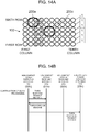
- FIG. 15A is a plan view schematically showing a situation of scan processing applied to the fourth column and the fifth column.
- FIG. 15B is a diagram showing a communication sequence between a non-contact power supplying appliance and non-contact power receiving appliances in the situation shown in FIG. 15A .
- controller 2 controls power supply units 1 meshed in a grey color in the fourth column and the fifth column so as to supply power necessary to operate communication unit 10 of non-contact power receiving appliance 200c.
- controller 2 further controls communication unit 5 so as to send a communication packet that stores a third response-request message, to communication address (03h) of non-contact power receiving appliance 200c.
- non-contact power receiving appliance 200c Because non-contact power receiving appliance 200c is placed on the fifth column and the sixth column, communication unit 10 of non-contact power receiving appliance 200c receives power transmitted from power supply unit 1 of the fifth column, and receives a third response message sent from communication unit 5.
- controller 11 controls communication unit 10 to send a magnitude of the power detected by power measuring unit 12 to non-contact power supplying appliance 100 as a third response message.
- controller 2 stores in storage unit 6, communication address (Olh) of non-contact power receiving appliance 200c and a magnitude of the power under reception.
- FIG. 16A is a plan view schematically showing a situation of scan processing applied to the fifth column and the sixth column.
- FIG. 16B is a diagram showing a communication sequence between a non-contact power supplying appliance and non-contact power receiving appliances in the situation shown in FIG. 16A .
- controller 2 controls power supply units 1 meshed in a grey color in the fifth column and the sixth column so as to supply power necessary to operate communication unit 10 of non-contact power receiving appliance 200c.
- Controller 2 further sends a communication packet that stores a third response-request message, to communication address (03h) of non-contact power receiving appliance 200c.
- non-contact power receiving appliance 200c Because non-contact power receiving appliance 200c is placed on the fifth column and the sixth column, communication unit 10 of non-contact power receiving appliance 200c receives power transmitted from power supply units 1 of the fifth column and the sixth column, and receives a third response-request message sent from communication unit 5.
- controller 11 controls communication unit 10 to send a magnitude of the power detected by power measuring unit 12, as a third response message.
- controller 2 stores in storage unit 6, communication address (03h) of non-contact power receiving appliance 200c and a magnitude of the power under reception.
- controller 2 can identify a row in which a magnitude of the power received by non-contact power receiving appliance 200c becomes largest, and can recognize that non-contact power receiving appliance 200c is placed on the fifth column and the sixth column.
- controller 2 understands that non-contact power receiving appliance 200c is placed on the fifth column, the sixth column of the third row, the fourth row, and stores a combination of non-contact power receiving appliance 200c and some of power supply units 1, in storage unit 6.
- non-contact power supplying appliance 100 transits from scan processing state 16 to registration state 17.
- registration state 17 identified non-contact power receiving appliances 200 are registered as power transmission targets, in a control target list held by storage unit 6.
- registration state 17 ends, and non-contact power supplying appliance 100 and non-contact power receiving appliance 200 transit to power supply state 18.
- FIG. 17A is a plan view schematically showing a situation that non-contact power receiving appliances 200a, 200c receive power.
- FIG. 17B is a diagram showing a communication sequence between a non-contact power supplying appliance and non-contact power receiving appliances in the situation shown in FIG. 17A .
- controller 2 Upon receiving an instruction to start power supply, controller 2 controls power supply units 1 combined with non-contact power receiving appliance 200 registered in the control target list so as to supply the same power as rated power of load 7 of non-contact power receiving appliance 200 registered in initial registration state 14, to non-contact power receiving appliance 200 detected in scan processing state 16 and registered in a control target list in registration state 17.
- Controller 2 controls communication unit 5 so as to periodically send a fourth response-request message for controlling power transmitted.
- controller 11 controls communication unit 10 to send a communication packet that stores a power error as a fourth response message corresponding to a fourth response-request message.
- controller 2 controls power supply units 1 combined with non-contact power receiving appliance 200 that has sent a fourth response message, so that a power error becomes zero, in non-contact power receiving appliance 200 that has sent the fourth response message.
- non-contact power receiving appliances 200a, 200c are detected, in placement detection state 15.
- scan processing state 16 it is identified that non-contact power receiving appliance 200a is combined with four power supply units 1 meshed in a grey color on the second column and the third column of the fifth row and the sixth row.
- non-contact power receiving appliance 200c is combined with four power supply units 1 meshed in a grey color on the fifth column and the sixth column of the third row and the fourth row.
- controller 2 controls power supply units 1 combined with non-contact power receiving appliance 200a, to supply the same power as the rated power of load 7 of non-contact power receiving appliance 200a registered in initial registration state 14, to load 7 of non-contact power receiving appliance 200a.
- Controller 2 further controls power supply units 1 combined with non-contact power receiving appliance 200c, to supply the same power as the rated power of load 7 of non-contact power receiving appliance 200c registered in initial registration state 14, to load 7 of non-contact power receiving appliance 200c.
- Controller 2 controls communication unit 5 so as to periodically send a fourth response-request message to each communication unit 10 of non-contact power receiving appliances 200a, 200c.
- controller 11 controls communication unit 10 to send a communication packet that stores a power error as a fourth response message.
- controller 11 controls communication unit 10 so as to send a communication packet that stores a power error as a fourth response message.
- controller 2 controls power supply units 1 combined with non-contact power receiving appliances 200a, 200c so as to set power errors stored in the two fourth response messages to zero.
- non-contact power supplying appliance 100 can be configured in a practicable scale.
- scan processing in a row direction in process (A) to process (C) scan processing in a column direction is implemented in process (D) to process (F).
- an implementation order may be set opposite.
- scan processing is started from the first row and the first column.
- scan processing may be started from an n-th row and an m-th column.
- controller 2 sets 2, as the numbers of rows and columns to which scan processing is executed simultaneously.
- controller 2 may determine the numbers of rows and columns to which scan processing is executed simultaneously, in accordance with diameters of coils included in resonance circuits 8.
- scan processing may be carried out individually.
- a diameter of a coil included in resonance circuit 8 of non-contact power receiving appliance 200a corresponds to a size for one power supply unit 1
- a diameter of each coil included in each resonance circuit 8 of non-contact power receiving appliances 200b, 200c corresponds to a size for three power supply units 1.
- process (A) to process (F) of the scan processing is executed, by setting 1 as the numbers of rows and columns to which scan processing is carried out.
- process (A) to process (F) of the scan processing is executed, by setting 3 as the numbers of rows and columns to which scan processing is carried out.
- a magnitude of the power received by a power receiving side in the scan is identified as one kind. Therefore, it is not necessary that the power receiving side sends a magnitude of the power under reception as a response message and a power supply side stores the response message. Accordingly, in this case, a system specification may be that only reception of power is transmitted as a response message.
- a power-receiving side communication unit has a MAC (medium access control) function having collision avoiding means such as CSMA(Carrier Sense Multiple Access), it is possible to provide a configuration for each power receiving appliance to send a response message in response to one response-request message in order while avoiding collision.
- MAC medium access control
- a non-contact power supplying appliance may send a response-request message by broadcast, and the non-contact power receiving appliance may send a response message in response to this response-request message.
- an address of the non-contact power receiving appliance is not required to be initially registered in advance.
- FIG. 18A is a plan view schematically showing a situation that during power transmission to non-contact power receiving appliances 200a, 200c, non-contact power receiving appliance 200a is removed from above non-contact power supplying appliance 100.
- FIG. 18B is a diagram showing a communication sequence between a non-contact power supplying appliance and a non-contact power receiving appliance in the situation shown in FIG. 18A .
- Non-contact power receiving appliance 200 includes on its bottom a push switch (not shown) as a switching unit that switches whether to supply power to load 7.
- the push switch is configured to be closed when non-contact power receiving appliance 200 is placed on non-contact power supplying appliance 100, and opened when non-contact power receiving appliance 200a is lifted for the sake of moving or the like.
- controller 11 controls communication unit 10 to send a communication packet that stores a fifth response message indicating that non-contact power receiving appliance 200a has moved.
- controller 2 stops power transmission to non-contact power receiving appliance 200a, and deletes information of non-contact power receiving appliance 200a from the control target list in order to remove non-contact power receiving appliance 200a from the power transmission targets.
- controller 2 when controller 2 does not receive a fourth response message during a predetermined period from non-contact power receiving appliance 200a for some reason after communication unit 5 sends a fourth response-request message to non-contact power receiving appliance 200a, controller 2 also similarly stops power transmission to non-contact power receiving appliance 200a, and deletes information of non-contact power receiving appliance 200a from the control target list in order to remove non-contact power receiving appliance 200a from the power transmission targets.
- FIG. 19A is a plan view schematically showing a situation that a non-contact power receiving appliance has moved to a position where power cannot be received.
- FIG. 19B is a diagram showing a communication sequence between a non-contact power supplying appliance and non-contact power receiving appliances in the situation shown in FIG. 19A .
- non-contact power supplying appliance 100 attempts to detect non-contact power receiving appliance 200a in placement detection state 15.
- controller 2 controls all power supply units 1 that are not in power supply state 18 so as to supply power necessary to operate communication units 10 of non-contact power receiving appliances 200 that are registered in initial registration state 14. Controller 2 further controls communication unit 5 so as to send a communication packet that stores a first response-request message, to communication addresses of non-contact power receiving appliances 200 that are registered in initial registration state 14.
- non-contact power receiving appliance 200a does not receive a first response-request message, and therefore, does not send a first response message.
- controller 2 decides that "there is no placement detection", and continues only power transmission to non-contact power receiving appliance 200c.
- FIG. 20A is a plan view schematically showing a situation that non-contact power receiving appliance 200a is placed on the ninth column, tenth column of the first row, second row of non-contact power supplying appliance 100.
- FIG. 20B is a diagram showing a communication sequence between a non-contact power supplying appliance and non-contact power receiving appliances in the situation shown in FIG. 20A .
- non-contact power supplying appliance 100 attempts to detect non-contact power receiving appliance 200a in placement detection state 15.
- controller 2 controls all power supply units 1 that are not in power supply state 18 so as to supply power necessary to operate communication units 10 of non-contact power receiving appliances 200 that are registered in initial registration state 14. Controller 2 further controls communication unit 5 so as to send a communication packet that stores a first response-request message, to communication addresses of non-contact power receiving appliances 200 that are registered in initial registration state 14.
- controller 11 controls communication unit 10 to send a communication packet that stores a magnitude of the power measured by power measuring unit 12, as a first response message.
- FIG. 21A , FIG. 22A , FIG. 23A are plan views schematically showing a situation of scan processing applied to non-contact power receiving appliance 200a after moving.
- FIG. 21B , FIG. 22B , FIG. 23B are diagrams showing a communication sequence between a non-contact power supplying appliance and non-contact power receiving appliances in the situation shown in FIG. 21A , FIG. 22A , FIG. 23B .
- FIG. 24A is a plan view schematically showing a situation that non-contact power receiving appliances 200a, 200c after moving receive power.
- FIG. 24B is a diagram showing a communication sequence between a non-contact power supplying appliance and non-contact power receiving appliances in the situation shown in FIG. 24A .
- the scan processing sown in FIG. 21A to FIG. 23B is similar to the scan processing shown in FIG. 7A to FIG. 16B .
- the power supply operation shown in FIG. 24A, FIG. 24B are similar to the power supply operation shown in FIG. 17A, FIG. 17B . Therefore, a description of the scan processing and the power supply operation will be omitted here.
- FIG. 25A is a plan view schematically showing an end of power supply operation to non-contact power receiving appliance 200a after moving.
- FIG. 25B is a diagram showing a communication sequence between a non-contact power supplying appliance and non-contact power receiving appliances in the situation shown in FIG. 25A .
- controller 2 controls communication unit 5 so as to send a communication packet indicating the end of power supply to non-contact power receiving appliances 200a 200c, and controls power supply unit 1 so as to stop the power supply.
- non-contact power supplying appliance 100 can stop power transmission.
- FIG. 26 is a block configuration diagram of non-contact power supplying appliance 101, non-contact power receiving appliance 201, and adapter appliance 300 according to the present exemplary embodiment.
- FIG. 27 is a plan view schematically showing a state that adapter appliance 300 is placed on non-contact power supplying appliance 101.
- non-contact power supplying appliance 101 is an induction heating cooker having a plurality of power supply units 1 arranged in a matrix shape, in a similar manner to that of non-contact power supplying appliance 100 in the first exemplary embodiment.
- Non-contact power supplying appliance 101 has zero-cross detector 23 that detects a zero-cross point of a commercial power source and sends a zero-cross point timing to controller 2, in addition to the configuration of non-contact power supplying appliance 100.
- Non-contact power receiving appliance 201 has resonance circuit 20 and resonance circuit 21, in a different manner from that of non-contact power receiving appliance 200 in the first exemplary embodiment.
- Resonance circuit 20 receives larger power than that supplied to only load 7, from non-contact power supplying appliance 100.
- Resonance circuit 21 receives smaller power than that supplied to only communication unit 10, from non-contact power supplying appliance 101.
- Communication unit 10 communicates with non-contact power supplying appliance 101 by superimposing a message on the power received, by load-modulating the power received via resonance circuit 21. That is, resonance circuit 21 is a power-receiving communication unit that receives power and sends and receives a communication packet.
- non-contact power receiving appliance 201 simplification of non-contact power receiving appliance 201 is possible.
- all power supply units 1 provided in non-contact power supplying appliance 101 have a communication function in a similar manner to that of the configuration of non-contact power receiving appliance 201.
- adapter appliance 300 is newly provided.
- adapter appliance 300 includes resonance circuit 24, high-frequency power source unit 22, resonance circuit 25, communication unit 26, controller 27, transfer unit 28, and appliance ID 19.
- Resonance circuit 24 is an adapter-side power receiving unit that contactlessly receives power from power supply unit 1 of non-contact power supplying appliance 101.
- High-frequency power source unit 22 receives power via resonance circuit 24 and power source circuit 9, and generates high-frequency power.
- Resonance circuit 25 communicates with non-contact power receiving appliance 201, by transmitting power supplied from high-frequency power source unit 22 to resonance circuit 21 of non-contact power receiving appliance 201 and by receiving information superimposed on power to be transmitted, from resonance circuit 21. That is, resonance circuit 25 is a power-supply communication unit that transmits power and sends and receives a communication packet.
- Communication unit 26 is an adapter-side communication unit that communicates with communication unit 5 of non-contact power supplying appliance 101.
- Controller 27 is an adapter-side controller that controls resonance circuit 25 via high-frequency power source unit 22 and controls communication unit 26.
- Transfer unit 28 transfers to controller 27, appliance information of non-contact power receiving appliance 201 superimposed on power transmitted from resonance circuit 25 to resonance circuit 21.
- appliance ID 19 is initially registered in storage unit 6 of non-contact power supplying appliance 101 as IDa.
- adapter appliance 300 contactlessly receives power from power supply unit 1 via resonance circuit 24. This power is controlled in accordance with information communicated between communication unit 5 and communication unit 26.
- Resonance circuit 25 is provided close to resonance circuit 21, and power contactlessly transmitted from resonance circuit 25 to resonance circuit 21 is supplied to communication unit 10 of non-contact power receiving appliance 201.
- Controller 11 of non-contact power receiving appliance 201 load-modulates the contactlessly transmitted power by using power source circuit 9, and controls communication unit 10 so as to transmit the power to adapter appliance 300 by superimposing a message for power control on the power transmitted.
- transfer unit 28 receives the message from non-contact power receiving appliance 201, and transfers the message to controller 27.
- Resonance circuit 20 of non-contact power receiving appliance 201 is positioned above one power supply unit 1, and receives power of this power supply unit 1.
- Appliance ID 19 of adapter appliance 300 is initially registered as IDc in storage unit 6 of non-contact power supplying appliance 101.
- Power supply unit 1 that transmits power to non-contact power receiving appliance 201 is controlled by adapter appliance 300 communicating with non-contact power supplying appliance 101 in place of non-contact power receiving appliance 201.
- Controller 2 of non-contact power supplying appliance 101 controls communication unit 5 to periodically send as a message a zero-cross point timing of a commercial power source obtained from zero-cross detector 23. Synchronously with a zero-cross point timing received by communication unit 26, controller 27 operates high-frequency power source unit 22.
- FIG. 28 is a diagram showing a communication sequence among non-contact power supplying appliance 101, non-contact power receiving appliance 201, and adapter appliance 300.
- Adapter appliance 300 has IDa and IDc, and by using IDa and IDc, communicates with non-contact power supplying appliance 101 and non-contact power receiving appliance 201.
- IDa is used to control power transmitted to adapter appliance 300.
- IDc is used to control power transmitted to non-contact power receiving appliance 201.
- a thick arrow between IDc of adapter appliance 300 and non-contact power receiving appliance 201 expresses power transmitted from resonance circuit 25 of adapter appliance 300 to resonance circuit 21 of non-contact power receiving appliance 201, and a thin arrow expresses communication of information.
- zero-cross means that a zero-cross point timing is sent as a message.
- a term "response request” means a response-request message.
- a term “response request Ra” means a response-request message to IDa, that is, adapter appliance 300.
- a term “response request Rc” means a response-request message to IDc, that is, non-contact power receiving appliance 201.
- a term "power error” means a power error sent as a message, in response to a response-request message.
- a term “power error Ea” means a power error concerning IDa, that is, adapter appliance 300c, and "power error Ec” means a power error concerning IDc, that is, non-contact power receiving appliance 201.
- non-contact power supplying appliance 101 periodically sends a zero-cross point timing of a commercial power source as a message, to IDa of adapter appliance 300.
- Adapter appliance 300 operates high-frequency power source unit 22 synchronously with this timing.
- Adapter appliance 300 sends to IDa, power error information (power error Ea) concerning adapter appliance 300, in response to a response-request message (response request Ra) received from non-contact power supplying appliance 101.
- power error Ea power error information
- response-request message response request Ra
- Non-contact power supplying appliance 101 controls power transmission to adapter appliance 300, in accordance with this error information.
- Adapter appliance 300 sends to IDc, power error information (power error Ec) concerning non-contact power receiving appliance 201, in response to a response-request message (response request Rc) received from non-contact power supplying appliance 101.
- power error Ec power error information
- response-request message response-request message
- Non-contact power supplying appliance 101 controls power transmission to non-contact power receiving appliance 201 via adapter appliance 300, in accordance with this error information.
- non-contact power receiving appliance 201 can be used above arbitrary power supply unit 1.
- a primary cell may be used in place of power source circuit 9 and resonance circuit 24.
- the power received may be accumulated in the secondary cell.
- resonance circuit 20 of non-contact power receiving appliance 201 may be used.
- Power supply unit 1 on which adapter appliance 300 is placed may be determined in advance.
- FIG. 29 is a block configuration diagram of non-contact power supplying appliance 101, non-contact power receiving appliance 201, and adapter appliance 301 according to the present exemplary embodiment.
- FIG. 30A to FIG. 30D are plan views schematically showing a state that adapter appliance 301 is placed on non-contact power supplying appliance 101.
- power source circuit 9 of adapter appliance 300 is not connected to load 7, and supplies power to light loads of communication unit 26 and controller 27 of adapter appliance 301, and communication unit 10 and controller 11 of non-contact power receiving appliance 201. Therefore, a size of power source circuit 9 is set to correspond to one power supply unit 1.
- a placement location of resonance circuit 24 of adapter appliance 300 can be identified by the scan processing, but a placement location of resonance circuit 20 of non-contact power receiving appliance 201 cannot be identified by the scan processing.
- adapter appliance 301 can be used at an arbitrary position above non-contact power supplying appliance 101.
- adapter appliance 301 in addition to the configuration of adapter appliance 300, resonance circuit 29 as a fourth power receiving unit and power source circuit 9 connected to resonance circuit 29 are added, and IDb is added as appliance ID 19.
- FIG. 30A to FIG. 30D are plan views schematically showing each situation that adapter appliance 301 is placed on non-contact power supplying appliance 101. As shown in FIG. 30A to FIG. 30D , when placement locations of resonance circuits 24, 29 are identified, a placement location of resonance circuit 20 can be identified.
- controllers 2, 11, 27 in the above exemplary embodiment are configured by microcomputers. Controllers 2, 11, 27 are not limited to microcomputers. However, when programmable microcomputers are used, a processing content can be easily changed, and degrees of freedom of design can be enhanced.
- controllers 2, 11, 27 can be also configured by logic circuits. Controllers 2, 11, 27 may be physically configured by one or a plurality of elements. In the case of configuring controllers 2, 11, 27 by a plurality of elements, each control element may be implemented by separate elements. In this case, these plurality of elements can be considered to correspond to one controller.
- the present disclosure is useful for a non-contact power transmitting system in which a non-contact power supplying appliance is an induction heating cooker having a plurality of power supply units arranged in a matrix shape.
Landscapes
- Engineering & Computer Science (AREA)
- Computer Networks & Wireless Communication (AREA)
- Power Engineering (AREA)
- Signal Processing (AREA)
- Physics & Mathematics (AREA)
- Electromagnetism (AREA)
- Charge And Discharge Circuits For Batteries Or The Like (AREA)
- Remote Monitoring And Control Of Power-Distribution Networks (AREA)
- Induction Heating Cooking Devices (AREA)
Claims (10)
- Kontaktloses Leistungsversorgungsgerät (100, 101), das konfiguriert ist, kontaktlos Leistung an ein kontaktloses Leistungsempfangsgerät (200, 200a, 200c) mit einer Last (7, 509) zu senden, wobei das kontaktlose Leistungsversorgungsgerät (100, 101) Folgendes umfasst:mehrere Leistungsversorgungseinheiten (1), die konfiguriert sind, die Leistung zu senden;eine leistungsversorgungsseitige Kommunikationseinheit (5), die konfiguriert ist, ein Kommunikationspaket zu senden und zu empfangen; undeine leistungsversorgungseitige Steuereinheit (2), die konfiguriert ist, die Leistungsversorgungseinheiten (1) und die leistungsversorgungsseitige Kommunikationseinheit (5) zu steuern,dadurch gekennzeichnet, dass die leistungsversorgungsseitige Kommunikationseinheit (5) konfiguriert ist, eine Positionierungsdetektion des kontaktlosen Leistungsempfangsgeräts (200, 200a, 200c) abzuschließen, wenn die leistungsversorgungsseitige Kommunikationseinheit (5) eine erste Antwortanforderungsnachricht für eine Positionierungsdetektion der kontaktlosen Leistungsempfangsgeräte (200, 200a, 200c) sendet und danach eine entsprechende erste Antwortnachricht empfängt, die eine Größe der Leistung bei Empfang durch das kontaktlose Leistungsempfangsgerät (200, 200a, 200c) enthält,wobei die leistungsversorgungsseitige Steuereinheit (2) konfiguriert ist, eine Kombination des kontaktlosen Leistungsempfangsgeräts (200, 200a, 200c) und einige der Leistungsversorgungseinheiten (1) zu identifizieren, wenn die leistungsversorgungsseitige Kommunikationseinheit (5) eine zweite und eine dritte Antwortanforderungsnachricht zum Identifizieren eines Positionierungsorts des kontaktlosen Leistungsempfangsgeräts (200, 200a, 200c) sendet und danach jeweils eine entsprechende zweite und dritte Antwortnachricht empfängt, die die Größe der Leistung bei Empfang durch das kontaktlose Leistungsempfangsgerät (299, 2a, 20c) enthalten, unddie leistungsversorgungsseitige Steuereinheit (2) konfiguriert ist, die identifizierten Leistungsversorgungseinheiten (1) in Übereinstimmung mit einer entsprechenden vierten Antwortnachricht, die durch die leistungsversorgungsseitige Kommunikationseinheit (5) empfangen wird und einen Unterschied zwischen der Größe der Leistung bei Empfang durch das kontaktlose Leistungsempfangsgerät (200, 200a, 200c) und einer Nennleistung der Last (7, 509) enthält, zu steuern, nachdem die leistungsversorgungsseitige Kommunikationseinheit (5) eine vierte Antwortanforderungsnachricht für eine Leistungssteuerung sendet.
- Kontaktloses Leistungsversorgungsgerät (100, 101) nach Anspruch 1, das ferner eine Speichereinheit (6) umfasst, die durch die leistungsversorgungsseitige Steuereinheit (2) gesteuert wird und Informationen speichert, die über die leistungsversorgungsseitige Kommunikationseinheit (5) kommuniziert werden,
wobei
die Leistungsversorgungseinheiten (1) in einer Matrixform angeordnet sind und,
um eine Kombination des kontaktlosen Leistungsempfangsgeräts (200, 200a, 200c) und der identifizierten Leistungsversorgungseinheiten (1) zu identifizieren, die leistungsversorgungsseitige Steuereinheit (2) konfiguriert ist, durch Steuern der Leistungsversorgungseinheiten (1), der leistungsversorgungsseitigen Kommunikationseinheit und der Speichereinheit (6) auszuführen:(A) einen Prozess des Ausführens einer Leistungsübertragung durch die Leistungsversorgungseinheiten (1) mindestens einer Reihe und Senden der zweiten Antwortanforderungsnachricht an das kontaktlose Leistungsempfangsgerät (200, 200a, 200c), dessen Positionierungsdetektion abgeschlossen ist,(B) einen Prozess nach dem Empfangen der zweiten Antwortanforderungsnachricht, die der zweiten Antwortanforderungsnachricht entspricht, des Speicherns einer Kommunikationsadresse des kontaktlosen Leistungsempfangsgeräts (200, 200a, 200c) und der Größe der Leistung bei Empfang durch das kontaktlose Leistungsempfangsgerät (200, 200a, 200c), die in der zweiten Antwortnachricht enthalten ist,(C) einen Prozess der Ausführens eines Prozesses (A) und eines Prozesses (B) an allen Reihen und Identifizieren einer Reihe, in der eine Größe der Leistung bei Empfang am größten wird,(D) einen Prozess des Ausführens einer Leistungsübertragung durch die Leistungsversorgungseinheiten (1) mindestens einer Spalte und Senden der dritten Antwortanforderungsnachricht an das kontaktlose Leistungsempfangsgerät (200, 200a, 200c), von dem die Positionierungsdetektion abgeschlossen ist,(E) einen Prozess nach dem Empfangen der dritten Antwortnachricht, die der dritten Antwortanforderungsnachricht entspricht, des Speicherns einer Kommunikationsadresse des kontaktlosen Leistungsempfangsgeräts (200, 200a, 200c) und der Größe der Leistung bei Empfang durch das kontaktlose Leistungsempfangsgerät (200, 200a, 200c), die in der dritten Antwortnachricht enthalten ist, und(F) einen Prozess des Ausführens eines Prozesses (D) und eines Prozesses (F) an allen Spalten und Identifizieren einer Spalte, in der die Größe der Leistung bei Empfang am größten wird. - Kontaktloses Leistungsversorgungsgerät (100, 101) nach Anspruch 2, wobei die leistungsversorgungsseitige Steuereinheit (2) konfiguriert ist, das kontaktlose Leistungsempfangsgerät (200, 200a, 200c), an das Leistung geliefert wird, von den Leistungsübertragungszielen auszuschließen, wenn die leistungsversorgungsseitige Kommunikationseinheit (5) die vierte Antwortnachricht nicht während einer vorgegebenen Periode von dem kontaktlosen Leistungsempfangsgerät (200, 200a, 200c) empfängt, das die Leistung empfängt, nachdem die leistungsversorgungsseitige Kommunikationseinheit (5) die vierte Antwortanforderungsnachricht an das kontaktlose Leistungsempfangsgerät (200, 200a, 200c), das Leistung empfängt, sendet.
- Kontaktloses Leistungsversorgungsgerät (100, 101) nach Anspruch 3, wobei die leistungsversorgungsseitige Steuereinheit (2) konfiguriert ist, nach dem Ausschließen des kontaktlosen Leistungsempfangsgeräts (200, 200a, 200c), das Leistung empfängt, von den Leistungsübertragungszielen eine Positionierungsdetektion auszuführen.
- Kontaktloses Leistungsversorgungsgerät (100, 101) nach Anspruch 4, wobei die leistungsversorgungsseitige Steuereinheit (2) konfiguriert ist, das kontaktlose Leistungsempfangsgerät (200, 200a, 200c), das von den Leistungsübertragungszielen ausgeschlossen ist, als eines der Leistungsübertragungsziele wieder zu registrieren, wenn das kontaktlose Leistungsempfangsgerät (200, 200a, 200c) wieder positioniert wird.
- Kontaktloses Leistungsempfangsgerät (200, 200a, 200c), das Leistung empfängt, die kontaktlos von einem kontaktlosen Leistungsversorgungsgerät (100, 101) gesendet wird, wobei das kontaktlose Leistungsempfangsgerät (200, 200a, 200c) umfasst:eine Leistungsempfangseinheit (8), die die Leistung empfängt;eine leistungsempfangsseitige Kommunikationseinheit (10), die ein Kommunikationspaket sendet und empfängt;eine Leistungsmesseinheit (12), die die Leistung bei Empfang durch die Leistungsempfangseinheit (8) misst; undeine Last (7, 509),dadurch gekennzeichnet, dassbeim Empfangen einer ersten Antwortanforderungsnachricht für eine Positionierungsdetektion des kontaktlosen Leistungsempfangsgeräts (200, 200a 200c) die leistungsempfangsseitige Kommunikationseinheit (10) eine entsprechende Antwortnachricht sendet, die eine Größe der durch die Leistungsmesseinheit (12) gemessenen Leistung enthält,beim Empfangen einer zweiten und einer dritten Antwortanforderungsnachricht zum Identifizieren eines Positionierungsorts des kontaktlosen Leistungsempfangsgeräts (200 200a, 200c) die leistungsempfangsseitige Kommunikationseinheit jeweils eine entsprechende zweite und dritte Antwortnachricht sendet, die die Größe der durch die Leistungsmesseinheit (12) gemessenen Leistung enthält, undbeim Empfang einer vierten Antwortanforderungsnachricht zum Steuern der gesendeten Leistung, die leistungsempfangsseitige Kommunikationseinheit (10) einen Unterschied zwischen der Größe der durch die Leistungsmesseinheit (12) gemessenen Leistung und der Nennleistung der Last (7, 50) als ein vierte Antwortnachricht sendet.
- Kontaktloses Leistungsempfangsgerät (200, 200a, 200c) nach Anspruch 6, das ferner umfasst:eine Schalteinheit, die geschlossen ist, wenn das kontaktlose Leistungsempfangsgerät (200, 200a, 200c) positioniert ist, und geöffnet ist, wenn die von dem kontaktlosen Leistungsversorgungsgerät (100, 101) gesendete Leistung an die Last (7, 509) geliefert wird, und das kontaktlose Leistungsempfangsgerät (200, 200a 200c) angehoben ist und die Zufuhr der Leistung an die Last (7, 509) stoppt,wobeidie leistungsempfangsseitige Kommunikationseinheit (10) konfiguriert ist, eine Antwortnachricht zu senden, die eine Bewegung des kontaktlosen Leistungsempfangsgeräts (200, 200a, 200c) angibt, wenn die Schalteinheit geöffnet wird.
- Kontaktloses Leistungsübertragungssystem, das Folgendes umfasst:das kontaktlose Leistungsversorgungsgerät (100, 101) nach Anspruch 1; unddas kontaktlose Leistungsempfangsgerät (200, 200a, 200c) nach Anspruch 6.
- Kontaktloses Leistungsübertragungssystem nach Anspruch 8, das ferner ein Adaptergerät (300, 301) umfasst, das die Leistung von dem kontaktlosen Leistungsversorgungsgerät (100, 101) empfängt und die Leistung an das kontaktlose Leistungsempfangsgerät (200, 200a, 200c) sendet und das Kommunikationspaket zwischen dem kontaktlosen Leistungsversorgungsgerät (100, 101) und dem kontaktlosen Leistungsempfangsgerät (200, 200a, 200c) sendet und empfängt, wobei
die leistungsempfangsseitige Kommunikationseinheit (10) eine Leistungsempfangskommunikationseinheit ist, die die Leistung empfängt, die durch die Last moduliert ist, um das Kommunikationspaket zu senden und zu empfangen,
das kontaktlose Leistungsversorgungsgerät (100, 101) ferner einen Nulldurchgangsdetektor (23) umfasst, der einen Nulldurchgangspunkt einer kommerziellen Leistungsquelle detektiert, und die leistungsversorgungsseitige Kommunikationseinheit (5) konfiguriert ist, einen Zeitpunkt eines Nulldurchgangspunkts an das Adaptergerät (300, 301) zu senden,
das Adaptergerät (300, 301) eine Leistungsversorgungskommunikationseinheit, die kontaktlos Leistung an die Leistungsempfangskommunikationseinheit (10) sendet und das Kommunikationspaket an die Leistungsempfangskommunikationseinheit (10) sendet und von ihr empfängt, und eine Adapterseitenkommunikationseinheit (26), die mit der leistungsversorgungsseitigen Kommunikationseinheit (5) kommuniziert, enthält,
die leistungsversorgungsseitige Kommunikationseinheit (5) den Nulldurchgangspunktzeitpunkt an die Adapterseitenkommunikationseinheit (26) sendet und die Leistungsversorgungskommunikationseinheit die Leistung sendet und das Kommunikationspaket in Übereinstimmung mit dem Nulldurchgangspunkt sendet und empfängt und
die leistungsversorgungsseitige Steuereinheit (2) konfiguriert ist, für eine Leistungssteuerung die Leistungsversorgungseinheiten (1) in Übereinstimmung mit dem durch die leistungsversorgungsseitige Kommunikationseinheit (5) empfangenen Kommunikationspaket zu steuern. - Kontaktloses Leistungsübertragungssystem nach Anspruch 9, wobei
das Adaptergerät (300, 301) ferner eine adapterseitige Leistungsempfangseinheit (24) besitzt, die die von dem kontaktlosen Leistungsversorgungsgerät (100, 101) kontaktlos gesendete Leistung empfängt,
die leistungsversorgungsseitige Steuereinheit (2) konfiguriert ist, eine Kombination der adapterseitigen Leistungsempfangseinheit (24) und einiger der Leistungsversorgungseinheiten (1) zu identifizieren, um einen Positionierungsort des kontaktlosen Leistungsempfangsgeräts (200, 200a, 200c) zu identifizieren.
Applications Claiming Priority (2)
| Application Number | Priority Date | Filing Date | Title |
|---|---|---|---|
| JP2015101858 | 2015-05-19 | ||
| PCT/JP2016/002324 WO2016185693A1 (ja) | 2015-05-19 | 2016-05-12 | 非接触給電機器および非接触受電機器、ならびに、これらを備えた非接触電力伝送システム |
Publications (3)
| Publication Number | Publication Date |
|---|---|
| EP3300213A1 EP3300213A1 (de) | 2018-03-28 |
| EP3300213A4 EP3300213A4 (de) | 2018-04-18 |
| EP3300213B1 true EP3300213B1 (de) | 2019-01-23 |
Family
ID=57319727
Family Applications (1)
| Application Number | Title | Priority Date | Filing Date |
|---|---|---|---|
| EP16796089.7A Active EP3300213B1 (de) | 2015-05-19 | 2016-05-12 | Kontaktlose leistungsversorgungsvorrichtung und kontaktlose leistungsempfangsvorrichtung sowie kontaktloses leistungsübertragungssystem damit |
Country Status (6)
| Country | Link |
|---|---|
| US (1) | US10340744B2 (de) |
| EP (1) | EP3300213B1 (de) |
| JP (1) | JP6751853B2 (de) |
| CN (3) | CN112234721A (de) |
| ES (1) | ES2721524T3 (de) |
| WO (1) | WO2016185693A1 (de) |
Families Citing this family (6)
| Publication number | Priority date | Publication date | Assignee | Title |
|---|---|---|---|---|
| US11689856B2 (en) | 2015-11-19 | 2023-06-27 | The Lovesac Company | Electronic furniture systems with integrated induction charger |
| WO2017170107A1 (ja) * | 2016-03-29 | 2017-10-05 | パナソニックIpマネジメント株式会社 | 非接触給電機器とこれを備えた非接触電力伝送システム |
| JP6939788B2 (ja) * | 2016-07-13 | 2021-09-22 | ソニーグループ株式会社 | 無線通信装置および無線通信方法 |
| CN109149794B (zh) * | 2017-06-28 | 2020-11-17 | 金宝电子工业股份有限公司 | 无线充电系统与无线充电方法 |
| EP3547487B1 (de) | 2018-03-29 | 2020-03-25 | NOK9 ip AB | Prüfungsvorrichtung zum prüfen einer vorrichtung zur drahtlosen stromübertragung und zugehöriges verfahren |
| CN112567592A (zh) * | 2018-08-21 | 2021-03-26 | 三菱电机株式会社 | 非接触供电系统、非接触供电用的受电设备以及基于非接触供电用的受电设备的启动信号发送方法 |
Family Cites Families (29)
| Publication number | Priority date | Publication date | Assignee | Title |
|---|---|---|---|---|
| US7378817B2 (en) * | 2003-12-12 | 2008-05-27 | Microsoft Corporation | Inductive power adapter |
| KR100792308B1 (ko) * | 2006-01-31 | 2008-01-07 | 엘에스전선 주식회사 | 코일 어레이를 구비한 무접점 충전장치, 무접점 충전시스템 및 충전 방법 |
| JP5094426B2 (ja) | 2008-01-08 | 2012-12-12 | 三菱電機株式会社 | 誘導加熱調理器及び誘導加熱調理器の制御方法 |
| JP2009271846A (ja) * | 2008-05-09 | 2009-11-19 | Harumi Takeda | ワイヤレスマウスの非接触給電システム |
| JP2010045960A (ja) * | 2008-07-16 | 2010-02-25 | Seiko Epson Corp | 送電制御装置、送電装置、受電制御装置、受電装置、電子機器、及び無接点電力伝送方法 |
| US8026466B2 (en) * | 2008-09-30 | 2011-09-27 | The Invention Science Fund I | Beam power with receiver impingement detection |
| EP2426809B1 (de) * | 2008-12-12 | 2018-08-08 | Intel Corporation | Kontaktlose Kraftübertragungsvorrichtung |
| JP2011205850A (ja) * | 2010-03-26 | 2011-10-13 | Panasonic Electric Works Co Ltd | 非接触受電装置及び非接触充電システム |
| CN103597697A (zh) * | 2011-06-09 | 2014-02-19 | 丰田自动车株式会社 | 受电装置、车辆以及非接触供电系统 |
| WO2013038694A1 (ja) * | 2011-09-14 | 2013-03-21 | パナソニック株式会社 | 非接触受電装置および非接触電力伝送装置 |
| CN104093771B (zh) * | 2012-02-09 | 2018-04-20 | 东丽株式会社 | 碳纤维复合材料 |
| US9018898B2 (en) * | 2012-02-10 | 2015-04-28 | Sandisk Technologies Inc. | Regulation of wirelessly charging multiple devices from the same source |
| CN104272557B (zh) * | 2012-05-11 | 2016-11-16 | 丰田自动车株式会社 | 输电装置、受电装置、车辆以及非接触供电系统 |
| US20150061398A1 (en) | 2012-09-03 | 2015-03-05 | Kabushiki Kaisha Toshiba | Power Transmitting Apparatus, Power Receiving Apparatus, and Wireless Power Transmission System |
| JP5801268B2 (ja) | 2012-09-03 | 2015-10-28 | 株式会社東芝 | 送電装置、受電装置および無線電力伝送システム |
| JP6092678B2 (ja) * | 2013-03-25 | 2017-03-08 | 日立マクセル株式会社 | 非接触電力伝送システム |
| JP2014220973A (ja) * | 2013-05-10 | 2014-11-20 | 船井電機株式会社 | 充電装置および充電方法 |
| RU2656246C2 (ru) | 2013-06-04 | 2018-06-04 | Конинклейке Филипс Н.В. | Беспроводная индуктивная передача энергии |
| WO2014204158A1 (en) | 2013-06-16 | 2014-12-24 | Lg Electronics Inc. | Wireless power transfer method, apparatus and system |
| CN103414258A (zh) * | 2013-08-13 | 2013-11-27 | 沈阳华立德电子科技有限公司 | 无线充电接收器 |
| JP2015042092A (ja) * | 2013-08-22 | 2015-03-02 | キヤノン株式会社 | 送電装置及びその制御方法、コンピュータプログラム |
| JP6242311B2 (ja) * | 2013-10-29 | 2017-12-06 | パナソニック株式会社 | 無線送電装置及び無線電力伝送システム |
| CN103560562B (zh) * | 2013-11-11 | 2016-05-18 | 天津工业大学 | 位置自适应无线充电耦合器 |
| US9608465B2 (en) * | 2014-04-18 | 2017-03-28 | Qualcomm Incorporated | Devices, systems, and method for power control of dynamic electric vehicle charging systems |
| US9438315B2 (en) * | 2014-07-03 | 2016-09-06 | ConvenientPower HK Ltd. | Wireless power adapter |
| WO2016024869A1 (en) * | 2014-08-12 | 2016-02-18 | Powerbyproxi Limited | System and method for power transfer |
| CN107078549A (zh) * | 2014-11-06 | 2017-08-18 | 富士通株式会社 | 受电器、以及电力传送系统 |
| JP6402818B2 (ja) * | 2015-02-20 | 2018-10-10 | 富士通株式会社 | 受電器、及び、電力伝送システム |
| WO2016140465A1 (ko) * | 2015-03-04 | 2016-09-09 | 엘지전자(주) | 무선 전력 송신기 및 수신기 |
-
2016
- 2016-05-12 CN CN202011283817.6A patent/CN112234721A/zh active Pending
- 2016-05-12 CN CN201680002283.0A patent/CN106716780B/zh active Active
- 2016-05-12 WO PCT/JP2016/002324 patent/WO2016185693A1/ja active Application Filing
- 2016-05-12 JP JP2017518751A patent/JP6751853B2/ja active Active
- 2016-05-12 EP EP16796089.7A patent/EP3300213B1/de active Active
- 2016-05-12 ES ES16796089T patent/ES2721524T3/es active Active
- 2016-05-12 US US15/503,042 patent/US10340744B2/en active Active
- 2016-05-12 CN CN202011283489.XA patent/CN112234720B/zh active Active
Non-Patent Citations (1)
| Title |
|---|
| None * |
Also Published As
| Publication number | Publication date |
|---|---|
| CN106716780B (zh) | 2021-01-01 |
| EP3300213A4 (de) | 2018-04-18 |
| US10340744B2 (en) | 2019-07-02 |
| ES2721524T3 (es) | 2019-08-01 |
| US20170229922A1 (en) | 2017-08-10 |
| CN112234720B (zh) | 2024-02-09 |
| EP3300213A1 (de) | 2018-03-28 |
| WO2016185693A1 (ja) | 2016-11-24 |
| CN106716780A (zh) | 2017-05-24 |
| CN112234721A (zh) | 2021-01-15 |
| JP6751853B2 (ja) | 2020-09-09 |
| CN112234720A (zh) | 2021-01-15 |
| JPWO2016185693A1 (ja) | 2018-03-08 |
Similar Documents
| Publication | Publication Date | Title |
|---|---|---|
| EP3300213B1 (de) | Kontaktlose leistungsversorgungsvorrichtung und kontaktlose leistungsempfangsvorrichtung sowie kontaktloses leistungsübertragungssystem damit | |
| KR102607753B1 (ko) | 무선 전력 전달 방법 및 이를 위한 장치 | |
| US10530426B2 (en) | Wireless power transferring method and device therefor | |
| KR102076859B1 (ko) | 무선 전력 전송 장치 및 무선 전력 전송 방법 | |
| CN108112279B (zh) | 具有同步功率测量的感应无线功率传输 | |
| EP2713472B1 (de) | Energieempfangs-Vorrichtung mit Vorrichtungsdetektion und Leistungsübertragung | |
| EP2752961B1 (de) | Drahtloses Ladegerät | |
| US20170133887A1 (en) | Contactless power receiver, contactless power feeder, and contactless power transmission system provided with same | |
| EP2884621B1 (de) | System zum drahtlosen aufladen eines elektronischen etiketts | |
| US11108270B2 (en) | Wireless power transmission system communication protocol | |
| EP3223386A1 (de) | Vorrichtung zur drahtlosen stromübertragung, vorrichtung zum drahtlosen stromempfang und system zur drahtlosen stromübertragung | |
| CN107078553A (zh) | 无线感应功率输送 | |
| CN109729748A (zh) | 无线充电系统中的无线电力发送方法和无线电力发送装置 | |
| EP4057777A1 (de) | Wpt-kochfeldvorrichtung und betriebsverfahren dafür | |
| CN103460712A (zh) | 终端设备、其通信方法以及通信模块 | |
| JP2011054093A (ja) | Rfidシステム | |
| CN109891706B (zh) | 能量输送设备和能量输送方法 | |
| WO2018030062A1 (ja) | 給電機器および受電機器、ならびに、これらを備えた電力伝送システム | |
| WO2017170107A1 (ja) | 非接触給電機器とこれを備えた非接触電力伝送システム | |
| KR20150077884A (ko) | 멀티 프로토콜 및 멀티 밴드 안테나를 이용한 무선충전 시스템 및 그 방법 | |
| CN210777126U (zh) | 一种红外对码无线遥控电磁炉 | |
| JP2015116066A (ja) | 電力伝送システム、電力伝送方法及びプログラム | |
| KR101066268B1 (ko) | 수동형 무선인식 태그 | |
| CN105682256A (zh) | 用于配置无线电网络的方法和无线电网络的中央站 |
Legal Events
| Date | Code | Title | Description |
|---|---|---|---|
| STAA | Information on the status of an ep patent application or granted ep patent |
Free format text: STATUS: THE INTERNATIONAL PUBLICATION HAS BEEN MADE |
|
| PUAI | Public reference made under article 153(3) epc to a published international application that has entered the european phase |
Free format text: ORIGINAL CODE: 0009012 |
|
| STAA | Information on the status of an ep patent application or granted ep patent |
Free format text: STATUS: REQUEST FOR EXAMINATION WAS MADE |
|
| 17P | Request for examination filed |
Effective date: 20170207 |
|
| AK | Designated contracting states |
Kind code of ref document: A1 Designated state(s): AL AT BE BG CH CY CZ DE DK EE ES FI FR GB GR HR HU IE IS IT LI LT LU LV MC MK MT NL NO PL PT RO RS SE SI SK SM TR |
|
| AX | Request for extension of the european patent |
Extension state: BA ME |
|
| A4 | Supplementary search report drawn up and despatched |
Effective date: 20180319 |
|
| RIC1 | Information provided on ipc code assigned before grant |
Ipc: H02J 50/80 20160101AFI20180313BHEP Ipc: H02J 7/02 20160101ALI20180313BHEP Ipc: H02J 50/90 20160101ALI20180313BHEP Ipc: H02J 50/40 20160101ALI20180313BHEP Ipc: H02J 7/00 20060101ALI20180313BHEP Ipc: H04B 5/00 20060101ALI20180313BHEP Ipc: H02J 50/12 20160101ALI20180313BHEP |
|
| DAV | Request for validation of the european patent (deleted) | ||
| DAX | Request for extension of the european patent (deleted) | ||
| GRAP | Despatch of communication of intention to grant a patent |
Free format text: ORIGINAL CODE: EPIDOSNIGR1 |
|
| STAA | Information on the status of an ep patent application or granted ep patent |
Free format text: STATUS: GRANT OF PATENT IS INTENDED |
|
| INTG | Intention to grant announced |
Effective date: 20180910 |
|
| GRAS | Grant fee paid |
Free format text: ORIGINAL CODE: EPIDOSNIGR3 |
|
| GRAA | (expected) grant |
Free format text: ORIGINAL CODE: 0009210 |
|
| STAA | Information on the status of an ep patent application or granted ep patent |
Free format text: STATUS: THE PATENT HAS BEEN GRANTED |
|
| AK | Designated contracting states |
Kind code of ref document: B1 Designated state(s): AL AT BE BG CH CY CZ DE DK EE ES FI FR GB GR HR HU IE IS IT LI LT LU LV MC MK MT NL NO PL PT RO RS SE SI SK SM TR |
|
| REG | Reference to a national code |
Ref country code: GB Ref legal event code: FG4D |
|
| REG | Reference to a national code |
Ref country code: CH Ref legal event code: EP |
|
| REG | Reference to a national code |
Ref country code: AT Ref legal event code: REF Ref document number: 1092219 Country of ref document: AT Kind code of ref document: T Effective date: 20190215 |
|
| REG | Reference to a national code |
Ref country code: IE Ref legal event code: FG4D |
|
| REG | Reference to a national code |
Ref country code: DE Ref legal event code: R096 Ref document number: 602016009514 Country of ref document: DE |
|
| REG | Reference to a national code |
Ref country code: NL Ref legal event code: MP Effective date: 20190123 |
|
| PG25 | Lapsed in a contracting state [announced via postgrant information from national office to epo] |
Ref country code: NL Free format text: LAPSE BECAUSE OF FAILURE TO SUBMIT A TRANSLATION OF THE DESCRIPTION OR TO PAY THE FEE WITHIN THE PRESCRIBED TIME-LIMIT Effective date: 20190123 |
|
| PG25 | Lapsed in a contracting state [announced via postgrant information from national office to epo] |
Ref country code: PL Free format text: LAPSE BECAUSE OF FAILURE TO SUBMIT A TRANSLATION OF THE DESCRIPTION OR TO PAY THE FEE WITHIN THE PRESCRIBED TIME-LIMIT Effective date: 20190123 Ref country code: NO Free format text: LAPSE BECAUSE OF FAILURE TO SUBMIT A TRANSLATION OF THE DESCRIPTION OR TO PAY THE FEE WITHIN THE PRESCRIBED TIME-LIMIT Effective date: 20190423 Ref country code: PT Free format text: LAPSE BECAUSE OF FAILURE TO SUBMIT A TRANSLATION OF THE DESCRIPTION OR TO PAY THE FEE WITHIN THE PRESCRIBED TIME-LIMIT Effective date: 20190523 Ref country code: SE Free format text: LAPSE BECAUSE OF FAILURE TO SUBMIT A TRANSLATION OF THE DESCRIPTION OR TO PAY THE FEE WITHIN THE PRESCRIBED TIME-LIMIT Effective date: 20190123 Ref country code: FI Free format text: LAPSE BECAUSE OF FAILURE TO SUBMIT A TRANSLATION OF THE DESCRIPTION OR TO PAY THE FEE WITHIN THE PRESCRIBED TIME-LIMIT Effective date: 20190123 Ref country code: LT Free format text: LAPSE BECAUSE OF FAILURE TO SUBMIT A TRANSLATION OF THE DESCRIPTION OR TO PAY THE FEE WITHIN THE PRESCRIBED TIME-LIMIT Effective date: 20190123 |
|
| REG | Reference to a national code |
Ref country code: ES Ref legal event code: FG2A Ref document number: 2721524 Country of ref document: ES Kind code of ref document: T3 Effective date: 20190801 |
|
| REG | Reference to a national code |
Ref country code: AT Ref legal event code: MK05 Ref document number: 1092219 Country of ref document: AT Kind code of ref document: T Effective date: 20190123 |
|
| PG25 | Lapsed in a contracting state [announced via postgrant information from national office to epo] |
Ref country code: IS Free format text: LAPSE BECAUSE OF FAILURE TO SUBMIT A TRANSLATION OF THE DESCRIPTION OR TO PAY THE FEE WITHIN THE PRESCRIBED TIME-LIMIT Effective date: 20190523 Ref country code: BG Free format text: LAPSE BECAUSE OF FAILURE TO SUBMIT A TRANSLATION OF THE DESCRIPTION OR TO PAY THE FEE WITHIN THE PRESCRIBED TIME-LIMIT Effective date: 20190423 Ref country code: LV Free format text: LAPSE BECAUSE OF FAILURE TO SUBMIT A TRANSLATION OF THE DESCRIPTION OR TO PAY THE FEE WITHIN THE PRESCRIBED TIME-LIMIT Effective date: 20190123 Ref country code: RS Free format text: LAPSE BECAUSE OF FAILURE TO SUBMIT A TRANSLATION OF THE DESCRIPTION OR TO PAY THE FEE WITHIN THE PRESCRIBED TIME-LIMIT Effective date: 20190123 Ref country code: HR Free format text: LAPSE BECAUSE OF FAILURE TO SUBMIT A TRANSLATION OF THE DESCRIPTION OR TO PAY THE FEE WITHIN THE PRESCRIBED TIME-LIMIT Effective date: 20190123 Ref country code: GR Free format text: LAPSE BECAUSE OF FAILURE TO SUBMIT A TRANSLATION OF THE DESCRIPTION OR TO PAY THE FEE WITHIN THE PRESCRIBED TIME-LIMIT Effective date: 20190424 |
|
| REG | Reference to a national code |
Ref country code: DE Ref legal event code: R097 Ref document number: 602016009514 Country of ref document: DE |
|
| PG25 | Lapsed in a contracting state [announced via postgrant information from national office to epo] |
Ref country code: CZ Free format text: LAPSE BECAUSE OF FAILURE TO SUBMIT A TRANSLATION OF THE DESCRIPTION OR TO PAY THE FEE WITHIN THE PRESCRIBED TIME-LIMIT Effective date: 20190123 Ref country code: SK Free format text: LAPSE BECAUSE OF FAILURE TO SUBMIT A TRANSLATION OF THE DESCRIPTION OR TO PAY THE FEE WITHIN THE PRESCRIBED TIME-LIMIT Effective date: 20190123 Ref country code: AL Free format text: LAPSE BECAUSE OF FAILURE TO SUBMIT A TRANSLATION OF THE DESCRIPTION OR TO PAY THE FEE WITHIN THE PRESCRIBED TIME-LIMIT Effective date: 20190123 Ref country code: RO Free format text: LAPSE BECAUSE OF FAILURE TO SUBMIT A TRANSLATION OF THE DESCRIPTION OR TO PAY THE FEE WITHIN THE PRESCRIBED TIME-LIMIT Effective date: 20190123 Ref country code: IT Free format text: LAPSE BECAUSE OF FAILURE TO SUBMIT A TRANSLATION OF THE DESCRIPTION OR TO PAY THE FEE WITHIN THE PRESCRIBED TIME-LIMIT Effective date: 20190123 Ref country code: DK Free format text: LAPSE BECAUSE OF FAILURE TO SUBMIT A TRANSLATION OF THE DESCRIPTION OR TO PAY THE FEE WITHIN THE PRESCRIBED TIME-LIMIT Effective date: 20190123 Ref country code: EE Free format text: LAPSE BECAUSE OF FAILURE TO SUBMIT A TRANSLATION OF THE DESCRIPTION OR TO PAY THE FEE WITHIN THE PRESCRIBED TIME-LIMIT Effective date: 20190123 |
|
| PG25 | Lapsed in a contracting state [announced via postgrant information from national office to epo] |
Ref country code: SM Free format text: LAPSE BECAUSE OF FAILURE TO SUBMIT A TRANSLATION OF THE DESCRIPTION OR TO PAY THE FEE WITHIN THE PRESCRIBED TIME-LIMIT Effective date: 20190123 |
|
| PLBE | No opposition filed within time limit |
Free format text: ORIGINAL CODE: 0009261 |
|
| STAA | Information on the status of an ep patent application or granted ep patent |
Free format text: STATUS: NO OPPOSITION FILED WITHIN TIME LIMIT |
|
| REG | Reference to a national code |
Ref country code: CH Ref legal event code: PL |
|
| PG25 | Lapsed in a contracting state [announced via postgrant information from national office to epo] |
Ref country code: AT Free format text: LAPSE BECAUSE OF FAILURE TO SUBMIT A TRANSLATION OF THE DESCRIPTION OR TO PAY THE FEE WITHIN THE PRESCRIBED TIME-LIMIT Effective date: 20190123 |
|
| 26N | No opposition filed |
Effective date: 20191024 |
|
| PG25 | Lapsed in a contracting state [announced via postgrant information from national office to epo] |
Ref country code: CH Free format text: LAPSE BECAUSE OF NON-PAYMENT OF DUE FEES Effective date: 20190531 Ref country code: LI Free format text: LAPSE BECAUSE OF NON-PAYMENT OF DUE FEES Effective date: 20190531 Ref country code: MC Free format text: LAPSE BECAUSE OF FAILURE TO SUBMIT A TRANSLATION OF THE DESCRIPTION OR TO PAY THE FEE WITHIN THE PRESCRIBED TIME-LIMIT Effective date: 20190123 |
|
| REG | Reference to a national code |
Ref country code: BE Ref legal event code: MM Effective date: 20190531 |
|
| PG25 | Lapsed in a contracting state [announced via postgrant information from national office to epo] |
Ref country code: SI Free format text: LAPSE BECAUSE OF FAILURE TO SUBMIT A TRANSLATION OF THE DESCRIPTION OR TO PAY THE FEE WITHIN THE PRESCRIBED TIME-LIMIT Effective date: 20190123 Ref country code: LU Free format text: LAPSE BECAUSE OF NON-PAYMENT OF DUE FEES Effective date: 20190512 |
|
| PG25 | Lapsed in a contracting state [announced via postgrant information from national office to epo] |
Ref country code: TR Free format text: LAPSE BECAUSE OF FAILURE TO SUBMIT A TRANSLATION OF THE DESCRIPTION OR TO PAY THE FEE WITHIN THE PRESCRIBED TIME-LIMIT Effective date: 20190123 |
|
| PG25 | Lapsed in a contracting state [announced via postgrant information from national office to epo] |
Ref country code: IE Free format text: LAPSE BECAUSE OF NON-PAYMENT OF DUE FEES Effective date: 20190512 |
|
| PG25 | Lapsed in a contracting state [announced via postgrant information from national office to epo] |
Ref country code: BE Free format text: LAPSE BECAUSE OF NON-PAYMENT OF DUE FEES Effective date: 20190531 |
|
| PG25 | Lapsed in a contracting state [announced via postgrant information from national office to epo] |
Ref country code: CY Free format text: LAPSE BECAUSE OF FAILURE TO SUBMIT A TRANSLATION OF THE DESCRIPTION OR TO PAY THE FEE WITHIN THE PRESCRIBED TIME-LIMIT Effective date: 20190123 |
|
| PG25 | Lapsed in a contracting state [announced via postgrant information from national office to epo] |
Ref country code: MT Free format text: LAPSE BECAUSE OF FAILURE TO SUBMIT A TRANSLATION OF THE DESCRIPTION OR TO PAY THE FEE WITHIN THE PRESCRIBED TIME-LIMIT Effective date: 20190123 Ref country code: HU Free format text: LAPSE BECAUSE OF FAILURE TO SUBMIT A TRANSLATION OF THE DESCRIPTION OR TO PAY THE FEE WITHIN THE PRESCRIBED TIME-LIMIT; INVALID AB INITIO Effective date: 20160512 |
|
| PG25 | Lapsed in a contracting state [announced via postgrant information from national office to epo] |
Ref country code: MK Free format text: LAPSE BECAUSE OF FAILURE TO SUBMIT A TRANSLATION OF THE DESCRIPTION OR TO PAY THE FEE WITHIN THE PRESCRIBED TIME-LIMIT Effective date: 20190123 |
|
| PGFP | Annual fee paid to national office [announced via postgrant information from national office to epo] |
Ref country code: FR Payment date: 20230424 Year of fee payment: 8 Ref country code: DE Payment date: 20230420 Year of fee payment: 8 |
|
| PGFP | Annual fee paid to national office [announced via postgrant information from national office to epo] |
Ref country code: GB Payment date: 20230419 Year of fee payment: 8 Ref country code: ES Payment date: 20230726 Year of fee payment: 8 |