EP3299569A1 - Dachfenster - Google Patents
Dachfenster Download PDFInfo
- Publication number
- EP3299569A1 EP3299569A1 EP17190696.9A EP17190696A EP3299569A1 EP 3299569 A1 EP3299569 A1 EP 3299569A1 EP 17190696 A EP17190696 A EP 17190696A EP 3299569 A1 EP3299569 A1 EP 3299569A1
- Authority
- EP
- European Patent Office
- Prior art keywords
- glazing
- frame
- roof window
- sash
- wing
- Prior art date
- Legal status (The legal status is an assumption and is not a legal conclusion. Google has not performed a legal analysis and makes no representation as to the accuracy of the status listed.)
- Granted
Links
Images

Classifications
-
- E—FIXED CONSTRUCTIONS
- E06—DOORS, WINDOWS, SHUTTERS, OR ROLLER BLINDS IN GENERAL; LADDERS
- E06B—FIXED OR MOVABLE CLOSURES FOR OPENINGS IN BUILDINGS, VEHICLES, FENCES OR LIKE ENCLOSURES IN GENERAL, e.g. DOORS, WINDOWS, BLINDS, GATES
- E06B7/00—Special arrangements or measures in connection with doors or windows
- E06B7/14—Measures for draining-off condensed water or water leaking-in frame members for draining off condensation water, throats at the bottom of a sash
-
- E—FIXED CONSTRUCTIONS
- E04—BUILDING
- E04D—ROOF COVERINGS; SKY-LIGHTS; GUTTERS; ROOF-WORKING TOOLS
- E04D13/00—Special arrangements or devices in connection with roof coverings; Protection against birds; Roof drainage ; Sky-lights
- E04D13/03—Sky-lights; Domes; Ventilating sky-lights
- E04D13/035—Sky-lights; Domes; Ventilating sky-lights characterised by having movable parts
-
- E—FIXED CONSTRUCTIONS
- E04—BUILDING
- E04D—ROOF COVERINGS; SKY-LIGHTS; GUTTERS; ROOF-WORKING TOOLS
- E04D13/00—Special arrangements or devices in connection with roof coverings; Protection against birds; Roof drainage ; Sky-lights
- E04D13/03—Sky-lights; Domes; Ventilating sky-lights
- E04D13/035—Sky-lights; Domes; Ventilating sky-lights characterised by having movable parts
- E04D13/0351—Sky-lights; Domes; Ventilating sky-lights characterised by having movable parts the parts pivoting about a fixed axis
- E04D13/0354—Sky-lights; Domes; Ventilating sky-lights characterised by having movable parts the parts pivoting about a fixed axis the parts being flat
-
- E—FIXED CONSTRUCTIONS
- E06—DOORS, WINDOWS, SHUTTERS, OR ROLLER BLINDS IN GENERAL; LADDERS
- E06B—FIXED OR MOVABLE CLOSURES FOR OPENINGS IN BUILDINGS, VEHICLES, FENCES OR LIKE ENCLOSURES IN GENERAL, e.g. DOORS, WINDOWS, BLINDS, GATES
- E06B7/00—Special arrangements or measures in connection with doors or windows
- E06B7/16—Sealing arrangements on wings or parts co-operating with the wings
-
- E—FIXED CONSTRUCTIONS
- E06—DOORS, WINDOWS, SHUTTERS, OR ROLLER BLINDS IN GENERAL; LADDERS
- E06B—FIXED OR MOVABLE CLOSURES FOR OPENINGS IN BUILDINGS, VEHICLES, FENCES OR LIKE ENCLOSURES IN GENERAL, e.g. DOORS, WINDOWS, BLINDS, GATES
- E06B7/00—Special arrangements or measures in connection with doors or windows
- E06B7/16—Sealing arrangements on wings or parts co-operating with the wings
- E06B7/22—Sealing arrangements on wings or parts co-operating with the wings by means of elastic edgings, e.g. elastic rubber tubes; by means of resilient edgings, e.g. felt or plush strips, resilient metal strips
- E06B7/23—Plastic, sponge rubber, or like strips or tubes
- E06B7/2305—Plastic, sponge rubber, or like strips or tubes with an integrally formed part for fixing the edging
-
- E—FIXED CONSTRUCTIONS
- E06—DOORS, WINDOWS, SHUTTERS, OR ROLLER BLINDS IN GENERAL; LADDERS
- E06B—FIXED OR MOVABLE CLOSURES FOR OPENINGS IN BUILDINGS, VEHICLES, FENCES OR LIKE ENCLOSURES IN GENERAL, e.g. DOORS, WINDOWS, BLINDS, GATES
- E06B7/00—Special arrangements or measures in connection with doors or windows
- E06B7/16—Sealing arrangements on wings or parts co-operating with the wings
- E06B7/22—Sealing arrangements on wings or parts co-operating with the wings by means of elastic edgings, e.g. elastic rubber tubes; by means of resilient edgings, e.g. felt or plush strips, resilient metal strips
- E06B7/23—Plastic, sponge rubber, or like strips or tubes
- E06B7/2314—Plastic, sponge rubber, or like strips or tubes characterised by the material
Definitions
- the invention relates to a roof window with a frame and with respect to the frame movable, a glazing-bearing casement, wherein the glazing is supported perpendicular to a glazing plane of the glazing on a sash of the sash, on which a sealing device is arranged.
- the roof window is intended for installation in a building, in particular in a roof of the building.
- the skylight has the frame, which is finally fixed stationary with respect to the building, and the sash.
- the casement is displaceable with respect to the frame, in particular rotatable about a rotation axis.
- the casement is preferably mounted on the frame.
- the sash frame carries the glazing of the skylight.
- the glazing can be designed as single glazing or as multiple glazing, in particular double glazing, triple glazing or quadruple glazing.
- the glazing is enclosed, for example, by wing frame members of the sash, in particular two vertical beams and two horizontal beams are provided.
- the above-mentioned wing frame spar is present as one of these wing frame spars.
- the frame also preferably has two vertical bars and two horizontal bars. In each case, two of the spars, so the sash or the frame beams are connected to each other, in particular, each of the vertical beams is connected to each of the horizontal bars
- the wing frame spar is formed, for example, as a plastic hollow profile or has such.
- the skylight may be present as a plastic roof window.
- the plastic hollow profile is produced, for example, by extrusion or the like and subsequent cutting to length.
- another embodiment of the wing frame spar is feasible.
- the wing frame spar is generally designed as a profile or hollow profile, which in principle may comprise any material or multiple materials.
- wood, metal and / or plastic can be used as material or materials.
- several of the wing frame spars consist of an identical profile.
- the vertical beams from the same first profile and / or the horizontal beams are made from the same second profile.
- at least one of the horizontal bars has the same profile as one of the vertical bars or consists of the corresponding profile.
- the profile has at least one hollow chamber, preferably a plurality of hollow chambers, which are separated from each other by stiffening webs.
- the roof window also has the sealing device. This is arranged on the sash, more precisely on the sash of the sash, in particular attached thereto.
- the attachment of the sealing device to the wing frame spar can be positive, non-positive and / or cohesive.
- the sealing device is used to seal the roof window, so that a separated by means of the roof window interior, in particular of the building, is protected from environmental influences from the outside environment. In that regard, the sealing device serves to seal an inner side of the roof window with respect to an outer side of the roof window.
- the casement spar has a side surface of the glazing partially overlapping securing projection for securing the glazing
- the sealing device comprises a arranged between the glazing and a support surface of the sash frame glass frame seal and a separately formed from the glass frame seal and spaced wing blade seal, wherein the sash seal with a closed roof window seen in cross section a Blendrahmenholm of the frame at least partially overlaps.
- the securing projection serves on the one hand the stiffening of the wing frame spar and on the other hand the securing of the glazing.
- the securing projection preferably forms a fall protection for the glazing, so that therefore even with a loosening connection between the glazing and the sash or the sash or a corresponding fastening a gravitational removal of the glazing of the sash, in particular an uncontrolled crash of the glazing of the roof of the building, is prevented by means of the securing projection.
- the securing projection is preferably on a lower horizontal spar of the casement, so that the above-described wing frame spar is designed as such a lower horizontal spar.
- the lower horizontal spar designates the lying horizontal in the installation position of the roof window horizontal spar or cross member of the sash.
- the glazing defines the glazing level. This preferably runs parallel to at least one glass pane of the glazing, in particular all glass panes of the glazing.
- the glazing level in the context of this description also means planes parallel to the actual glazing plane.
- the securing projection engages over the side surface of the glazing at least partially. The side surface is angled here with respect to the glazing plane, in particular it is perpendicular to this.
- the glazing is initially arranged spaced from the securing projection, so that therefore the side surface is parallel spaced apart from the securing projection.
- the glazing unit only comes into contact with the securing projection when it is released from its fastening, which subsequently prevents the glazing from being removed from the sash frame by its supporting effect.
- the glazing with the side surface immediately after the installation of the roof window already applied to the securing projection.
- the securing projection is provided with an elastic element against which the glazing bears that between the securing projection and the glazing, such an elastic element is arranged.
- the glazing is only indirectly, namely on the elastic element, on the securing projection.
- the elastic element may for example be molded onto the securing projection.
- the glazing is supported perpendicular to the glazing on the wing frame spar.
- This can either be the case directly, so that the glazing rests directly on the casement spar.
- an indirect support of the glazing on the casement spar can also be provided.
- a support element for example the glass frame seal mentioned below, is arranged between the casement spar and the glazing.
- the wing frame or the wing frame spar thus serves to support or support the glazing.
- the securing projection forms a fall protection for the glazing, in that it is arranged such that the glazing with its side surface is supported on it or can be supported on it by a gravity-induced displacement.
- the securing projection preferably extends in the manner of a web over the entire extension of the wing frame spar in the direction of its longitudinal central axis. Of course, no continuous course of the securing projection must be provided, although this is preferred.
- the sealing device Due to the formation of the securing projection on the wing frame spar achieving an excellent tightness of the roof window is a special challenge. It is provided for this purpose to design the sealing device in several parts, this having on the one hand the glass frame seal and on the other hand the wing frame seal.
- the glass frame seal serves to seal the glazing relative to the sash frame or sash so that passage of moisture between the glazing and the sash frame spar is prevented by the glass frame seal.
- the sash seal serves to seal the sash frame with respect to the frame, in particular the covering and / or closing of an air gap present between the sash frame and the frame.
- the glass frame seal and / or the wing frame seal preferably extend in each case over the entire length of the wing frame spar in the direction of its longitudinal central axis.
- the glass frame seal and the sash seal are spaced from each other on the wing frame spar arranged, in particular fixed.
- the Glass frame seal between the glazing and the wing frame spar clamped.
- the glazing is supported by the glass frame seal on the wing frame spar.
- the glass frame seal Seen in cross section, ie in a section perpendicular to the longitudinal central axis of the sash frame spar and perpendicular to the glazing plane, the glass frame seal is present in the region of the glazing, so it is overlapped by the glazing.
- the wing frame seal is preferably arranged at a distance from the glazing viewed in cross section. In order to seal the air gap between the frame and the sash by means of the sash seal as described above, this overlaps the frame frame spar of the frame at least partially in the roof window when viewed in cross section.
- the casement spar and the frame spar are preferably arranged parallel to each other, in particular spaced parallel to each other.
- the wing frame seal completely overlaps the frame spar. In particular, as seen in cross section, it engages over a roofing sheet metal sheet fastened to the window frame, which rests, for example, on a roof skin, at least in regions.
- a development of the invention provides that the sash seal seen in cross section arranged between the sash and the frame spar, attached to the sash spar dam block and / or attached to the frame spar holding profile for holding a Eindeckrahmenblechs to the frame and / or one in the holding profile engages engaging vertical web of the Eindeckrahmenblechs.
- the insulating block may be provided. This is particularly preferably arranged on the wing frame spar, in particular fastened. This means that the insulating block is displaced with a displacement of the sash with respect to the frame together with the sash.
- the wing frame seal may also overlap the retaining profile and / or the vertical web of Eindeckrahmenblechs.
- the retaining profile serves to hold the Eindeckrahmenblechs.
- the retaining profile with the wing frame spar or a locking profile arranged on this is verklipsbar.
- the holding profile serves the Fixing the roof cover plate to the frame.
- the Eindeckrahmenblech engages with its vertical web in the holding profile.
- a further preferred embodiment of the invention provides that the sash seal with a closed roof window sealingly rests on an upper side of the frame spar and / or the holding profile. Due to the tight contact the excellent tightness of the roof window is achieved, in particular by closing the air gap against the outside environment.
- the wing-frame seal rests against the upper side of the frame profile or of the retaining profile at least in regions. Particularly preferably, it rests against both the frame profile and the retaining profile.
- a development of the invention provides that the wing frame seal is held in a form-fitting manner in a fastening groove of the wing frame spar.
- the fastening groove preferably extends over the entire longitudinal extension of the wing frame spar.
- the mounting groove is open with the roof window closed in the direction of the window frame.
- the wing frame seal has a foot region from which, on the one hand, a sealing projection engaging in the fastening groove and, on the other hand, a sealing wing extending in the direction away from the glazing emanate.
- the foot area serves to support the sash seal on the sash or the sash.
- the foot area is located on the entire surface of the wing frame spar, in particular on opposite sides of the mounting groove.
- the positive locking projection extends, which engages in the fastening groove, namely in such a way that the wing frame seal is held in a form-fitting manner on the wing frame spar.
- the sealing wing of the sash seal extends. Seen in cross-section, the sealing wing engages over the frame frame spar of the frame at least in regions. In particular, the sealing wing also overlaps the insulating block. For example, it is at least partially closed at the dormer window with the roof window closed.
- a further embodiment of the invention provides that the foot region is arranged between the casement spar and the insulating block.
- the Dämmblock overlaps so far in Cross-section seen the mounting groove of the wing frame spar, so that the foot area - again seen in cross section - is arranged between the casement spar and the insulating block.
- the insulating block can be designed such that it rests against the wing frame seal, for example, such that it urges the foot area in the direction of the mounting groove and so far holds the positive locking projection in the mounting groove or at least urges in their direction.
- the insulating block can prevent unintentional removal of the sash seal from the sash spar so far.
- a further preferred embodiment of the invention provides that seen in cross-section the foot region rests on both sides on a fastening web of the wing frame spar, wherein one of the fastening webs of a fastening, in particular a latching attachment, of the insulating block on the casement serves. Seen in cross-section, the fastening webs of the sash frame spar extend in the direction away from the fastening groove, in particular in the direction of the window frame when the roof window is closed.
- the fastening webs take the foot area in cross-section between them.
- one of the fastening webs rests on the one hand on the foot region and the other of the fastening webs on the other hand against the foot region, so that the foot region is held in a form-fitting manner between the fastening webs.
- the mounting webs can also take on other tasks.
- one of the fastening webs of attachment of the insulating block In particular, the fastening web is designed such that the insulating block can be locked with it.
- a preferred embodiment of the invention provides that, seen in cross-section, one of the fastening webs forms an acute angle with the securing projection and projects from the foot region into the direction away from the respective other of the fastening webs.
- the attachment web is so far angled with respect to the securing projection, thus enclosing with this an angle which is greater than 0 ° and less than 180 °.
- the angle is greater than 0 ° and is at most 90 °.
- it is smaller than 90 °, so that it is in the form of an acute angle.
- the fastening web is arranged such that its free end, viewed in cross section, protrudes away from the other of the fastening webs.
- the wing frame seal in particular the sealing wing, has an angled sealing web on its side facing away from the foot region.
- the wing frame seal is configured so hook-shaped.
- the sealing web forms a free end of the wing frame seal, which is present on its side facing away from the foot region and / or the form-fitting projection side of the wing frame seal.
- At the sealing ridge there is a free edge of the wing frame seal or the sealing wing.
- the sealing web is angled with respect to a subsequent region of the wing blade seal, for example by an angle which is at least 45 °, at least 90 ° or more than 90 °.
- the sealing web is angled in the direction of the roof, so that the free edge preferably forms a drip edge.
- a further preferred embodiment of the invention provides that the wing frame seal in cross-section is at least partially arcuate, in particular has a bent portion extending from the foot region to the sealing region.
- the arcuate or curved portion of the wing frame seal is continuously curved in cross-section, so far as it has a non-zero curvature.
- the curvature is constant over at least part of the extension of the sash seal in the direction away from the foot region. It is particularly preferably constant throughout, ie starting from the foot region up to the angled sealing web.
- the glass frame seal seen in cross-section has two projecting in the opposite direction sealing lips which abut the glazing, wherein the sealing lips emanate from a hollow profile of the glass frame seal.
- the glass frame seal thus has at least the hollow profile and the two sealing lips.
- the hollow profile has at least one cavity or alternatively a plurality of cavities separated by separating webs.
- the hollow profile allows for easy deformation of the glass frame seal in order to achieve a particularly good sealing effect.
- From the hollow profile go out of the at least two sealing lips.
- the sealing lips extend in opposite directions, for example, one of the sealing lips in the direction of the frame spar and the other in the direction away from the frame spar Holm direction. Both sealing lips abut the glazing.
- the sealing lips extend spaced apart from each other in parallel. For this they go - seen in cross-section - preferably from opposite sides of the hollow profile.
- a further embodiment of the invention provides that one of the sealing lips is held in a clamping manner between regions of the glazing and a support web of the wing frame spar, wherein the support web rests against the hollow profile.
- the support bar protrudes in the direction of the glazing. He lies on the sealing lip in some areas and urges them in the direction or to the glazing.
- the sealing lip is partially and only partially held by clamping between the glazing and the support web.
- the side facing away from the hollow profile of the sealing lip is spaced from the support web and so far freely movable, so that it rests flexible on the glazing.
- the support web abuts against the hollow profile, namely in particular on one side of the hollow profile from which the support web extends. In this way, the support web preferably serves to position the glass frame seal during assembly of the roof window.
- the glass frame seal has an outgoing from the hollow profile, extending to an edge of the sash frame support area, which is arranged spaced from the glazing.
- the support area serves to support the glass frame seal on the casement spar.
- the support area is continuous and flat on the casement spar, in particular starting from the hollow profile to the edge of the wing frame spar.
- a preferred embodiment of the invention provides that viewed in cross section, the securing projection engages only partially against a glass pane of the glazing resting against the glass frame seal or projects up to its edge facing away from the glass frame seal. Accordingly, the securing projection does not completely overlap the glazing, but only the one glass pane.
- the glass pane is preferably the glass pane of the glazing facing the sash frame spar, should the glazing have several glass panes.
- the securing projection overlaps a plurality of glass panes of the glazing, in particular partially or completely.
- a further embodiment of the invention provides that the securing projection is spaced from the support web, in particular spaced apart in parallel.
- the glass frame seal is spaced from the securing projection.
- One of the Sealing lips now extend in the direction of the securing projection, while the other of the sealing lips protrudes in the direction away from the securing projection direction.
- At least one drainage channel is formed on the casement, in particular at least partially on a further casement spar adjoining the casement spar.
- the gutter is used to dissipate moisture, which is understood by the moisture, for example, precipitation and / or condensate. Of course, solids can be removed by means of the gutter. However, this is not dealt with separately.
- the gutter is located on the casement. In particular, it is formed on the further wing frame spar, which adjoins the wing frame spar, in particular connected thereto or fastened to it.
- the further casement spar for example, is present as a vertical spar of the casement.
- a channel-like depression present in the wing frame spar at least partially forms the drainage channel.
- the gutter is open edge in front of the sash. This means that the gutter is seen in cross-section with respect to its longitudinal extent as limited by a bottom and two side walls, which are formed by the wing frame spar.
- a further preferred embodiment of the invention provides that the glass frame seal has at least one passage recess which forms part of the gutter.
- the gutter should pass through the glass frame seal.
- the glass frame seal has the passage opening.
- the passage recess is for example designed such that the above-mentioned contact area of the glass frame seal represents the bottom of the gutter, while in the region of the passage recess, the sealing lips and / or the hollow profile are not present or recessed.
- the passage opening establishes a flow connection between the drainage channel and an external environment of the skylight.
- the passage opening is designed such that the moisture from the drainage channel on a Top of the sash seal can escape, so that it is subsequently discharged along the top, in particular by gravity.
- the passage opening is present on the side facing away from the wing frame seal of the adjacent to the support web of the fastening webs.
- the passage opening does not engage in the fastening web, but ends flush with the top.
- FIG. 1 shows a schematic sectional view of a roof window 1, which has a frame 2 and a sash 3.
- the sash frame 3 is displaceable with respect to the frame 2, in particular rotatable about a rotation axis.
- the frame 2 has a frame spar 4 and the sash 3 has a wing frame spar 5.
- Both the frame spar 4 and the wing frame spar 5 are designed, for example, in each case as a plastic profile, in particular as a hollow plastic profile. An embodiment as a wood or metal profile is of course feasible.
- the frame spar 4 and the wing frame spar 5 are arranged substantially parallel to one another. Shown here is a section through the skylight 1 perpendicular to a longitudinal central axis of the frame spar 4 or the wing frame spar 5.
- the frame spar and the coperahmenholm 5 are each in front of the lower horizontal spar of the frame 2 and the sash 3.
- the roof window 1 has a glazing 6, which is configured in the embodiment shown here as a multiple glazing, namely more precisely as triple glazing. Accordingly, the glazing has 6 over three glass sheets 7, 8 and 9, which are arranged parallel spaced from each other.
- the glazing 6 lies in a glazing plane or defines it.
- the glazing plane is parallel to the glass panes 7, 8 and 9.
- the glazing 6 is supported on the wing frame spar 5.
- a support element 10 is provided, via which the glazing 6 is supported on the casement spar 5.
- a fall protection for the glazing 6 of the sash 5 has a securing projection 11 which is formed in the manner of a web and preferably extends over the entire width of the sash 5.
- the securing projection 11 overlaps the glazing 6 at least partially, in particular only partially, when viewed in cross-section.
- the securing projection 11 is arranged substantially parallel to a side surface of the glazing 6 or one of the glass panes 7, 8 or 9.
- the securing projection 11, seen in cross section only overlaps the glass pane 7 facing the sash frame spar 5 and only partially.
- the securing projection 11 is preferably spaced from the glazing 6, so it does not touch.
- the roof window 1 has a sealing device 12, which is arranged on the sash frame 3, in particular on the sash frame spar 5.
- the sealing device 12 has a glass frame seal 13 and a wing frame seal 14.
- the glass frame seal 13 and the wing frame seal 14 are formed separately from each other and spaced from each other, in particular spaced from each other attached to the sash spar.
- the sealing device 12 is designed so far multipart.
- the sealing device 12 or the glass frame seal 13 and the wing frame seal 14 are preferably made of a flexible sealing material, in particular of rubber or a comparable material.
- the glass frame seal 13 has a hollow profile 15, from which two sealing lips 16 and 17 as well as a support region 18 originate.
- the sealing lips 16 and 17 extend in cross-section seen in opposite directions, namely the sealing lip 16 of the frame spar 4 and the sealing lip 17 in the direction of the frame spar 4. Both sealing lips 16 and 17 sealingly against the glazing 6, namely on the glass pane. 7 , at.
- the sealing lip 17 is held in regions between the glazing 6 and a support web 19 by clamping. It has in the direction of the glazing 6 a lower height than the support element 10. For example, the support web 19 and the sealing lip 17 in total to a height corresponding to the height of the support member 10.
- the support web 19 rests not only on the sealing lip 17, but in addition to the hollow profile 15.
- the support bar 19 serves as a positioning aid for the glass frame seal 13 during assembly of the roof window 1.
- the support area 18 extends from the hollow section 15 to a peripheral edge 20 of the sash 5.
- the sealing device 12 has the wing frame seal 14. This is held in a form-fitting manner in a fastening groove 21 of the wing frame spar 5.
- the wing frame seal 14 has a positive locking projection 22, which starts from a foot region 23 of the wing frame seal 14 and is held in a form-fitting manner in the fastening groove 21.
- the foot region 23 is present outside of the fastening groove 21, but on both sides of a passage opening through which the form-fitting projection 23 enters the fastening groove 21, on the sash 5. In this way, excellent positional stability of the sash seal 14 is provided. In particular, tilting of the sash seal 14 is prevented.
- the wing frame seal 14 has a sealing wing 24 which extends from the foot region 23 in the direction of the frame spar 4.
- the sealing wing 24 lies on the side facing away from the form-fitting projection 22 side of the foot portion 23.
- the foot region 23 may be held between fastening webs 25 and 26.
- the foot region 23 abuts the attachment web 25 on the one hand and the attachment web 26 on the other hand.
- the fastening web 25 preferably includes an acute angle with the securing projection 11, that is to say an angle which is smaller than 90 °.
- the angle between the fastening web 26 and the securing projection 11, however, can correspond exactly to 90 °.
- the wing frame seal 14, in particular the sealing wing 24 extends arcuately at least in some areas.
- it has a curved region 27 which extends directly from the foot region 23 and projects up to an angled sealing web 28 on which there is a free end of the sealing blade 24.
- the bent portion 27 is preferably curved starting from the foot portion 23 to the sealing ridge 28, thus always has a curvature which is different from zero.
- the region 27 is preferably configured in such a way that, viewed in cross-section, it first rises starting from the foot region 23 and subsequently falls off again.
- the region 27 runs in a direction perpendicular to the glass plane first in the direction of the glazing 6 and subsequently away from it, ie in the direction away from the glazing 6 direction.
- the region 27 is designed, for example, such that the sealing web 28, seen in cross-section, lies above the foot region 23.
- the free end of the sealing web 28 or the sealing wing 24 can be at the same height as an upper side of the foot region 23.
- the wing frame seal 14 is intended to overlap the frame frame spar 4 at least in regions, in particular as shown completely here.
- the wing frame seal 14 projects beyond the frame spar 4 in the direction away from the wing frame spar 5.
- it lies with closed roof window 1 with its sealing wing 24 on the frame spar 4.
- it is particularly preferably applied to a retaining profile 29, which is fastened to the frame spar 4 and serves to hold a cover frame sheet (not shown here). To its holder engages the Eindeckrahmenblech with a vertical web, also not shown in the retaining profile 29 a.
- an insulating block 30 can be arranged between the frame 2 and the sash 3, in particular between the frame spar 4 and the sash 5.
- the insulating block 30 is attached to the casement spar.
- the fastening web 26 which can be configured for latching attachment of the insulating block 30 to the sash 5.
- the wing frame seal 14, in particular its sealing wing 24, completely engages over the insulating block 30 when the skylight 1 is closed. In this case, it preferably lies flat against the insulating block 30.
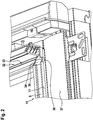
- FIG. 2 shows a further illustration of the roof window 1, wherein individual elements are cut or not shown at all.
- the wing frame spar 5 is adjoined by a further wing frame spar 32, which is preferably designed as a vertical spar of the wing frame 3.
- the sash spar 5 and the further sash 32 are attached to each other, in particular to miter surfaces secured together.
- a gutter 33 is at least partially formed.
- the wing frame spar 5 is a channel-like recess 34, which also forms a region of the gutter 33.
- the glass cream seal 13 has a passage recess 35, which also represents a part of the gutter 33.
- the support area 18 or an upper side of the support area 18 forms a bottom of the drainage channel 33.
- the sealing lips 16 and 17 and the hollow profile 15 are removed.
- the securing projection 11 has a passage opening 36. This is designed such that the moisture from the gutter 23 on an upper surface 37 of the sash seal 14 and can be removed via this. The moisture is carried over the air gap 31 and over the frame spar 4 and can subsequently escape from the skylight 1 down.
- the sealing web 28 or its free edge forms a drip edge of the wing frame seal 14.
Landscapes
- Engineering & Computer Science (AREA)
- Civil Engineering (AREA)
- Structural Engineering (AREA)
- Architecture (AREA)
- Securing Of Glass Panes Or The Like (AREA)
- Specific Sealing Or Ventilating Devices For Doors And Windows (AREA)
Abstract
Description
- Die Erfindung betrifft ein Dachfenster mit einem Blendrahmen und einem bezüglich des Blendrahmens verlagerbaren, eine Verglasung tragenden Flügelrahmen, wobei sich die Verglasung senkrecht zu einer Verglasungsebene der Verglasung an einem Flügelrahmenholm des Flügelrahmens abstützt, an dem eine Dichtungsvorrichtung angeordnet ist.
- Das Dachfenster ist zum Einbau in ein Gebäude, insbesondere in ein Dach des Gebäudes, vorgesehen. Das Dachfenster verfügt über den Blendrahmen, welcher schlussendlich ortsfest bezüglich des Gebäudes befestigt wird, und den Flügelrahmen. Der Flügelrahmen ist bezüglich des Blendrahmens verlagerbar, insbesondere um eine Drehachse drehbar. Hierzu ist der Flügelrahmen vorzugsweise an dem Blendrahmen gelagert. Der Flügelrahmen trägt die Verglasung des Dachfensters. Die Verglasung kann als Einfachverglasung oder als Mehrfachverglasung, insbesondere Doppelverglasung, Dreifachverglasung oder Vierfachverglasung, ausgestaltet sein. Die Verglasung ist beispielsweise von Flügelrahmenholmen des Flügelrahmens eingefasst, wobei insbesondere zwei Vertikalholme und zwei Horizontalholme vorgesehen sind. Der eingangs bezeichnete Flügelrahmenholm liegt als einer dieser Flügelrahmenholme vor. Auch der Blendrahmen verfügt bevorzugt über zwei Vertikalholme und zwei Horizontalholme. Dabei sind jeweils zwei der Holme, also der Flügelrahmenholme oder der Blendrahmenholme, miteinander verbunden, insbesondere ist jeder der Vertikalholme mit jedem der Horizontalholme verbunden.
- Der Flügelrahmenholm ist beispielsweise als Kunststoffhohlprofil ausgebildet beziehungsweise weist ein solches auf. Das Dachfenster kann insoweit als Kunststoffdachfenster vorliegen. Das Kunststoffhohlprofil wird beispielsweise durch Extrudieren oder dergleichen und anschließendem Ablängen hergestellt. Auch eine andere Ausgestaltung des Flügelrahmenholms ist jedoch realisierbar. Beispielsweise liegt der Flügelrahmenholm ganz allgemein als Profil oder Hohlprofil ausgestaltet, welches grundsätzlich ein beliebiges Material oder mehrere Materialen aufweisen kann. So können als Material oder Materialien beispielsweise Holz, Metall und/oder Kunststoff verwendet werden. Bevorzugt bestehen mehrere der Flügelrahmenholme aus einem identischen Profil.
- Beispielsweise sind die Vertikalholme aus dem gleichen ersten Profil und/oder die Horizontalholme aus dem gleichen zweiten Profil hergestellt. Es kann jedoch auch vorgesehen sein, dass wenigstens einer der Horizontalholme das gleiche Profil aufweist wie einer der Vertikalholme beziehungsweise aus dem entsprechend Profil besteht. Im Falle des Hohlprofils, insbesondere des Kunststoffhohlprofils, weist das Profil wenigstens eine Hohlkammer, vorzugsweise eine Vielzahl von Hohlkammern auf, welche von Versteifungsstegen voneinander getrennt sind. Mit einer derartigen Ausgestaltung des Profils kann eine hohe Steifigkeit bei gleichzeitig geringem Gewicht erzielt werden.
- Das Dachfenster weist zudem die Dichtungsvorrichtung auf. Diese ist an dem Flügelrahmen, genauer gesagt an dem Flügelrahmenholm des Flügelrahmens angeordnet, insbesondere an diesem befestigt. Die Befestigung der Dichtungsvorrichtung an dem Flügelrahmenholm kann formschlüssig, kraftschlüssig und/oder stoffschlüssig sein. Die Dichtungsvorrichtung dient der Abdichtung des Dachfensters, sodass ein mittels des Dachfensters abgetrennter Innenraum, insbesondere des Gebäudes, vor Umgebungseinflüssen aus der Außenumgebung geschützt ist. Insoweit dient die Dichtungsvorrichtung dazu, eine Innenseite des Dachfensters gegenüber einer Außenseite des Dachfensters abzudichten.
- Es ist Aufgabe der Erfindung ein Dachfenster vorzuschlagen, welches gegenüber bekannten Dachfenstern Vorteile aufweist, insbesondere eine hohe Stabilität und gleichzeitig eine hervorragende Dichtheit aufweist.
- Dies wird erfindungsgemäß mit einem Dachfenster mit den Merkmalen des Anspruchs 1 erreicht. Dabei ist vorgesehen, dass der Flügelrahmenholm einen eine Seitenfläche der Verglasung teilweise übergreifenden Sicherungsvorsprung zur Sicherung der Verglasung aufweist, und dass die Dichtungsvorrichtung eine zwischen der Verglasung und einer Auflagefläche des Flügelrahmenholms angeordnete Glasrahmendichtung sowie eine von der Glasrahmendichtung separat ausgebildete und beabstandet angeordnete Flügelrahmendichtung aufweist, wobei die Flügelrahmendichtung bei geschlossenem Dachfenster im Querschnitt gesehen einen Blendrahmenholm des Blendrahmens wenigstens bereichsweise übergreift.
- Der Sicherungsvorsprung dient zum einen der Versteifung des Flügelrahmenholms und andererseits der Sicherung der Verglasung. Der Sicherungsvorsprung bildet bevorzugt eine Absturzsicherung für die Verglasung, sodass also auch bei einer sich lösenden Verbindung zwischen der Verglasung und dem Flügelrahmen beziehungsweise dem Flügelrahmenholm oder einer entsprechenden Befestigung ein schwerkraftbedingtes Entfernen der Verglasung von dem Flügelrahmen, insbesondere ein unkontrollierter Absturz der Verglasung von dem Dach des Gebäudes, mittels des Sicherungsvorsprungs unterbunden wird. Hierzu liegt der Sicherungsvorsprung bevorzugt an einem unteren Horizontalholm des Flügelrahmens vor, sodass der eingangs bezeichnete Flügelrahmenholm als ein solcher unterer Horizontalholm ausgestaltet ist. Der untere Horizontalholm bezeichnet dabei den in Einbaulage des Dachfensters unten liegenden Horizontalholm beziehungsweise Querholm des Flügelrahmens.
- Die Verglasung definiert die Verglasungsebene. Diese verläuft vorzugsweise parallel zu wenigstens einer Glasscheibe der Verglasung, insbesondere allen Glasscheiben der Verglasung. Unter der Verglasungsebene im Rahmen dieser Beschreibung sind auch zu der eigentlichen Verglasungsebene parallele Ebenen zu verstehen. Der Sicherungsvorsprung übergreift die Seitenfläche der Verglasung zumindest teilweise. Die Seitenfläche ist hierbei bezüglich der Verglasungsebene angewinkelt, insbesondere steht sie senkrecht auf dieser.
- Es kann vorgesehen sein, dass nach der Montage des Dachfensters die Verglasung zunächst beabstandet zu dem Sicherungsvorsprung angeordnet ist, sodass also die Seitenfläche parallel beabstandet zu dem Sicherungsvorsprung vorliegt. Bei einer derartigen Ausgestaltung des Dachfensters gerät die Verglasung erst bei einem Lösen ihrer Befestigung in Anlagekontakt mit dem Sicherungsvorsprung, welcher nachfolgend das Entfernen der Verglasung von dem Flügelrahmen durch seine Abstützwirkung unterbindet.
- Alternativ kann es selbstverständlich auch vorgesehen sein, dass die Verglasung mit der Seitenfläche unmittelbar nach der Montage des Dachfensters bereits an dem Sicherungsvorsprung anliegt. Um in diesem Fall eine Kraftbeaufschlagung der Verglasung bei temperaturbedingten Abmessungsänderungen des Flügelrahmenholms von dem Sicherungsvorsprung zu vermeiden, bei welcher Spannungen in der Verglasung auftreten können, kann es vorgesehen sein, dass der Sicherungsvorsprung mit einem elastischen Element versehen ist, an dem die Verglasung anliegt, oder dass zwischen dem Sicherungsvorsprung und der Verglasung ein solches elastisches Element angeordnet ist. Anders ausgedrückt liegt die Verglasung also lediglich mittelbar, nämlich über das elastische Element, an dem Sicherungsvorsprung an. Das elastische Element kann beispielsweise an den Sicherungsvorsprung angespritzt sein.
- Zusammenfassend stützt sich die Verglasung senkrecht zu der Verglasung an dem Flügelrahmenholm ab. Dies kann entweder direkt der Fall sein, sodass also die Verglasung unmittelbar an dem Flügelrahmenholm anliegt. Auch ein indirektes Abstützen der Verglasung an dem Flügelrahmenholm kann jedoch vorgesehen sein. In diesem Fall ist zwischen dem Flügelrahmenholm und der Verglasung ein Stützelement, beispielsweise die nachfolgend noch erwähnte Glasrahmendichtung, angeordnet. Bei dem Abstützen in senkrechter Richtung muss nicht notwendigerweise eine Stützkraft in dieser Richtung vorliegen beziehungsweise auf die Verglasung wirken. Es ist ausreichend, wenn das die Verglasung benachbart zu dem Flügelrahmenholm vorliegt und bezüglich des Flügelrahmens und mithin des Flügelrahmenholms befestigt ist.
- Einerseits dient der Flügelrahmen beziehungsweise der Flügelrahmenholm also dem Tragen beziehungsweise Abstützen der Verglasung. Zusätzlich bildet der Sicherungsvorsprung eine Absturzsicherung für die Verglasung, indem er derart angeordnet ist, dass sich die Verglasung mit ihrer Seitenfläche an ihm abstützt oder bei einer schwerkraftbedingten Verlagerung an ihm abstützen kann. Der Sicherungsvorsprung erstreckt sich vorzugsweise nach Art eines Stegs über die gesamte Erstreckung des Flügelrahmenholms in Richtung von dessen Längsmittelachse. Selbstverständlich muss dabei kein durchgehender Verlauf des Sicherungsvorsprungs vorgesehen sein, wenngleich dies bevorzugt ist.
- Aufgrund der Ausbildung des Sicherungsvorsprungs an dem Flügelrahmenholm ist das Erzielen einer hervorragenden Dichtheit des Dachfensters eine besondere Herausforderung. Es ist hierzu vorgesehen, die Dichtungsvorrichtung mehrteilig auszugestalten, wobei diese zum einen die Glasrahmendichtung und zum anderen die Flügelrahmendichtung aufweist. Die Glasrahmendichtung dient der Abdichtung der Verglasung gegenüber dem Flügelrahmen beziehungsweise des Flügelrahmenholms, sodass ein Hindurchtreten von Feuchtigkeit zwischen der Verglasung und dem Flügelrahmenholm mittels der Glasrahmendichtung unterbunden wird. Die Flügelrahmendichtung dient dagegen dem Abdichten des Flügelrahmens bezüglich des Blendrahmens, insbesondere dem Abdecken und/oder Verschließen eines zwischen dem Flügelrahmen und dem Blendrahmen vorliegenden Luftspalts.
- Die Glasrahmendichtung und/oder die Flügelrahmendichtung erstrecken sich bevorzugt jeweils über die gesamte Länge des Flügelrahmenholms in Richtung von dessen Längsmittelachse. Die Glasrahmendichtung und die Flügelrahmendichtung sind beabstandet voneinander an dem Flügelrahmenholm angeordnet, insbesondere befestigt. Beispielsweise ist die Glasrahmendichtung zwischen der Verglasung und dem Flügelrahmenholm klemmend gehalten. Insbesondere stützt sich die Verglasung über die Glasrahmendichtung an dem Flügelrahmenholm ab. Im Querschnitt gesehen, also in einem Schnitt senkrecht zu der Längsmittelachse des Flügelrahmenholms und senkrecht auf der Verglasungsebene, liegt die Glasrahmendichtung im Bereich der Verglasung vor, wird also von der Verglasung übergriffen.
- Die Flügelrahmendichtung ist dagegen bevorzugt im Querschnitt gesehen von der Verglasung beabstandet angeordnet. Um wie vorstehend beschrieben den Luftspalt zwischen dem Blendrahmen und dem Flügelrahmen mittels der Flügelrahmendichtung abzudichten, übergreift diese bei geschlossenem Dachfenster im Querschnitt gesehen den Blendrahmenholm des Blendrahmens wenigstens bereichsweise. Der Flügelrahmenholm und der Blendrahmenholm sind bevorzugt parallel zueinander angeordnet, insbesondere beabstandet parallel zueinander. Besonders bevorzugt übergreift die Flügelrahmendichtung den Blendrahmenholm vollständig. Insbesondere übergreift sie im Querschnitt gesehen ein an dem Blendrahmen befestigtes Eindeckrahmenblech, welches zum Beispiel auf einer Dachhaut aufliegt, zumindest bereichsweise. Mit einer derartigen Ausgestaltung des Dachfensters werden zum einen eine hohe mechanische Stabilität des Dachfensters und zum anderen eine hervorragende Dichtheit erzielt.
- Eine Weiterbildung der Erfindung sieht vor, dass die Flügelrahmendichtung im Querschnitt gesehen einen zwischen dem Flügelrahmenholm und dem Blendrahmenholm angeordneten, an dem Flügelrahmenholm befestigten Dämmblock und/oder ein an dem Blendrahmenholm befestigtes Halteprofil zur Halterung eines Eindeckrahmenblechs an dem Blendrahmen und/oder einen in das Halteprofil eingreifenden Vertikalsteg des Eindeckrahmenblechs übergreift. Zur Verbesserung der Dämmung des Dachfensters kann der Dämmblock vorgesehen sein. Dieser ist besonders bevorzugt an dem Flügelrahmenholm angeordnet, insbesondere befestigt. Das bedeutet, dass der Dämmblock bei einer Verlagerung des Flügelrahmens bezüglich des Blendrahmens gemeinsam mit dem Flügelrahmen verlagert wird. Der vorstehend beschriebene Luftspalt liegt, sofern der Dämmblock vorgesehen ist, zwischen dem Dämmblock und dem Blendrahmen im Querschnitt gesehen vor.
- Zusätzlich oder alternativ kann die Flügelrahmendichtung auch das Halteprofil und/oder den Vertikalsteg des Eindeckrahmenblechs übergreifen. Das Halteprofil dient der Halterung des Eindeckrahmenblechs. Insbesondere ist das Halteprofil mit dem Flügelrahmenholm beziehungsweise einem an diesem angeordneten Rastprofil verklipsbar. Das Halteprofil dient der Befestigung des Eindeckrahmenblechs an dem Blendrahmen. Hierzu greift das Eindeckrahmenblech mit seinem Vertikalsteg in das Halteprofil ein.
- Eine weitere bevorzugte Ausführungsform der Erfindung sieht vor, dass die Flügelrahmendichtung bei geschlossenem Dachfenster auf einer Oberseite des Blendrahmenholms und/oder des Halteprofils dichtend aufliegt. Durch das dichte Aufliegen wird die hervorragende Dichtheit des Dachfensters erzielt, insbesondere durch das Verschließen des Luftspalts gegenüber der Außenumgebung. Die Flügelrahmendichtung liegt hierzu bei zumindest bereichsweise auf der Oberseite des Blendrahmenprofils oder des Halteprofils auf. Besonders bevorzugt liegt sie sowohl an dem Blendrahmenprofil als auch dem Halteprofil an.
- Eine Weiterbildung der Erfindung sieht vor, dass die Flügelrahmendichtung in einer Befestigungsnut des Flügelrahmenholms formschlüssig gehalten ist. Die Befestigungsnut erstreckt sich vorzugsweise über die gesamte Längserstreckung des Flügelrahmenholms. Die Befestigungsnut ist bei geschlossenem Dachfenster in Richtung des Blendrahmens geöffnet.
- Im Rahmen einer weiteren Ausführungsform der Erfindung ist vorgesehen, dass die Flügelrahmendichtung einen Fußbereich aufweist, von dem einerseits ein in die Befestigungsnut eingreifender Formschlussvorsprung und andererseits ein sich in die von der Verglasung abgewandte Richtung erstreckender Dichtungsflügel ausgehen. Der Fußbereich dient der Abstützung der Flügelrahmendichtung an dem Flügelrahmen beziehungsweise dem Flügelrahmenholm. Vorzugsweise liegt der Fußbereich vollflächig an dem Flügelrahmenholm an, insbesondere auf gegenüberliegenden Seiten der Befestigungsnut.
- Von dem Fußbereich geht einerseits der Formschlussvorsprung aus, welcher in die Befestigungsnut eingreift, nämlich derart, dass die Flügelrahmendichtung formschlüssig an dem Flügelrahmenholm gehalten ist. In die von dem Formschlussvorsprung und mithin in die von der Verglasung abgewandte Richtung erstreckt sich der Dichtungsflügel der Flügelrahmendichtung. Der Dichtungsflügel übergreift im Querschnitt gesehen den Blendrahmenholm des Blendrahmens wenigstens bereichsweise. insbesondere übergreift der Dichtungsflügel zudem den Dämmblock. Beispielsweise liegt er bei geschlossenem Dachfenster wenigstens bereichsweise an dem Dämmblock an.
- Eine weitere Ausführungsform der Erfindung sieht vor, dass der Fußbereich zwischen dem Flügelrahmenholm und dem Dämmblock angeordnet ist. Der Dämmblock übergreift insoweit im Querschnitt gesehen die Befestigungsnut des Flügelrahmenholms, sodass der Fußbereich - wiederum im Querschnitt gesehen - zwischen dem Flügelrahmenholm und dem Dämmblock angeordnet ist. Der Dämmblock kann dabei derart ausgestaltet sein, dass er an der Flügelrahmendichtung anliegt, beispielsweise derart, dass er den Fußbereich in Richtung der Befestigungsnut drängt und insoweit den Formschlussvorsprung in der Befestigungsnut hält oder zumindest in deren Richtung drängt. Der Dämmblock kann insoweit ein unbeabsichtigtes Entfernen der Flügelrahmendichtung von dem Flügelrahmenholm verhindern.
- Eine weitere bevorzugte Ausgestaltung der Erfindung sieht vor, dass der Fußbereich im Querschnitt gesehen beidseitig jeweils an einem Befestigungssteg des Flügelrahmenholms anliegt, wobei einer der Befestigungsstege einer Befestigung, insbesondere einer rastenden Befestigung, des Dämmblocks an dem Flügelrahmen dient. Die Befestigungsstege des Flügelrahmenholms erstrecken sich im Querschnitt gesehen in die von der Befestigungsnut abgewandte Richtung, insbesondere bei geschlossenem Dachfenster in die Richtung des Blendrahmens.
- Die Befestigungsstege nehmen den Fußbereich im Querschnitt gesehen zwischen sich auf. Insbesondere liegt einer der Befestigungsstege einerseits an dem Fußbereich und der andere der Befestigungsstege andererseits an dem Fußbereich an, sodass der Fußbereich zwischen den Befestigungsstegen formschlüssig gehalten ist. Neben dem Halten der Flügelrahmendichtung können die Befestigungsstege auch andere Aufgaben übernehmen. So dient einer der Befestigungsstege der Befestigung des Dämmblocks. Insbesondere ist der Befestigungssteg derart ausgestaltet, dass der Dämmblock mit ihm verrastbar ist.
- Eine bevorzugte Ausführungsform der Erfindung sieht vor, dass einer der Befestigungsstege im Querschnitt gesehen mit dem Sicherungsvorsprung einen spitzen Winkel einschließt und ausgehend von dem Fußbereich in die von dem jeweils anderen der Befestigungsstege abgewandte Richtung ragt. Der Befestigungssteg ist insoweit bezüglich des Sicherungsvorsprungs angewinkelt, schließt also mit diesem einen Winkel ein, welcher größer als 0° und kleiner als 180° ist. Insbesondere ist der Winkel größer als 0° und beträgt höchstens 90°. Insbesondere ist er jedoch kleiner als 90°, sodass er in Form eines spitzen Winkels vorliegt. Der Befestigungssteg ist derart angeordnet, dass sein freies Ende im Querschnitt gesehen von dem anderen der Befestigungsstege fort ragt.
- Bevorzugt kann in einer weiteren Ausgestaltung der Erfindung vorgesehen sein, dass die Flügelrahmendichtung, insbesondere der Dichtungsflügel auf seiner dem Fußbereich abgewandten Seite, einen abgewinkelten Dichtungssteg aufweist. Die Flügelrahmendichtung ist insoweit hakenförmig ausgestaltet. Der Dichtungssteg bildet ein freies Ende der Flügelrahmendichtung aus, welche auf ihrer dem Fußbereich und/oder dem Formschlussvorsprung abgewandten Seite der Flügelrahmendichtung vorliegt. An dem Dichtungssteg liegt eine freie Kante der Flügelrahmendichtung beziehungsweise des Dichtungsflügels vor. Der Dichtungssteg ist gegenüber einem sich an ihn anschließenden Bereich der Flügelrahmendichtung angewinkelt, beispielsweise um einen Winkel, der mindestens 45°, mindestens 90° oder mehr als 90° beträgt. Der Dichtungssteg ist dabei in Richtung des Dachs angewinkelt, sodass die freie Kante vorzugsweise eine Abtropfkante bildet.
- Eine weitere bevorzugte Ausgestaltung der Erfindung sieht vor, dass die Flügelrahmendichtung im Querschnitt gesehen zumindest bereichsweise bogenförmig ist, insbesondere einen sich von dem Fußbereich bis zu dem Dichtungsbereich erstreckenden gebogenen Bereich aufweist. Darunter ist zu verstehen, dass der bogenförmige beziehungsweise gebogene Bereich der Flügelrahmendichtung im Querschnitt gesehen durchgehend gekrümmt ist, insoweit also eine von Null verschiedene Krümmung aufweist. Vorzugsweise ist die Krümmung über zumindest einen Teil der Erstreckung der Flügelrahmendichtung in die von dem Fußbereich abgewandte Richtung konstant. Besonders bevorzugt ist sie durchgehend konstant, also ausgehend von dem Fußbereich bis hin zu dem angewinkelten Dichtungssteg.
- Bevorzugt kann es weiterhin vorgesehen sein, dass die Glasrahmendichtung im Querschnitt gesehen zwei in die entgegengesetzte Richtung ragende Dichtlippen aufweist, die an der Verglasung anliegen, wobei die Dichtlippen von einem Hohlprofil der Glasrahmendichtung ausgehen. Die Glasrahmendichtung weist also zumindest das Hohlprofil und die beiden Dichtlippen auf. Das Hohlprofil verfügt über wenigstens einen Hohlraum oder alternativ mehrere durch Trennstege getrennte Hohlräume. Das Hohlprofil ermöglicht eine einfache Verformung der Glasrahmendichtung, um eine besonders gute Dichtwirkung zu erzielen. Von dem Hohlprofil gehen die wenigstens zwei Dichtlippen aus. Im Querschnitt gesehen erstrecken sich die Dichtlippen in entgegengesetzte Richtungen, beispielsweise eine der Dichtlippen in Richtung des Blendrahmenholms und die andere in die von dem Blendrahmenholm abgewandte Richtung. Beide Dichtlippen liegen an der Verglasung an. Vorzugsweise verlaufen die Dichtlippen beabstandet parallel voneinander. Hierzu gehen sie - im Querschnitt gesehen - vorzugsweise von gegenüberliegenden Seiten des Hohlprofils aus.
- Eine weitere Ausgestaltung der Erfindung sieht vor, dass eine der Dichtlippen bereichsweise zwischen der Verglasung und einem Stützsteg des Flügelrahmenholms klemmend gehalten ist, wobei der Stützsteg an dem Hohlprofil anliegt. Der Stützsteg ragt in Richtung der Verglasung. Er liegt an der Dichtlippe bereichsweise an und drängt diese in Richtung beziehungsweise an die Verglasung. Insoweit ist die Dichtlippe bereichsweise und nur bereichsweise klemmend zwischen der Verglasung und dem Stützsteg gehalten. Die dem Hohlprofil abgewandte Seite der Dichtlippe ist dagegen beabstandet von dem Stützsteg angeordnet und insoweit frei beweglich, sodass sie flexibel an der Verglasung anliegt. Der Stützsteg liegt an dem Hohlprofil an, nämlich insbesondere an einer Seite des Hohlprofils, von welcher der Stützsteg ausgeht. Auf diese Art und Weise dient der Stützsteg vorzugsweise der Positionierung der Glasrahmendichtung bei der Montage des Dachfensters.
- Eine Weiterbildung der Erfindung sieht vor, dass die Glasrahmendichtung einen von dem Hohlprofil ausgehenden, sich bis zu einer Randkante des Flügelrahmenholms erstreckenden Auflagebereich aufweist, der von der Verglasung beabstandet angeordnet ist. Der Auflagebereich dient dem Abstützen der Glasrahmendichtung an dem Flügelrahmenholm. Vorzugsweise liegt der Auflagebereich durchgehend und flächig an dem Flügelrahmenholm an, insbesondere ausgehend von dem Hohlprofil bis hin zu der Randkante des Flügelrahmenholms.
- Eine bevorzugte Ausgestaltung der Erfindung sieht vor, dass im Querschnitt gesehen der Sicherungsvorsprung eine an der Glasrahmendichtung anliegende Glasscheibe der Verglasung nur teilweise übergreift oder bis hin zu ihrer der Glasrahmendichtung abgewandten Kante ragt. Entsprechend übergreift der Sicherungsvorsprung die Verglasung nicht vollständig, sondern lediglich die eine Glasscheibe. Die Glasscheibe ist bevorzugt die dem Flügelrahmenholm zugewandte Glasscheibe der Verglasung, sollte die Verglasung über mehrere Glasscheiben verfügen. Selbstverständlich kann es alternativ vorgesehen sein, dass der Sicherungsvorsprung mehrere Glasscheiben der Verglasung übergreift, insbesondere teilweise oder vollständig.
- Eine weitere Ausgestaltung der Erfindung sieht vor, dass der Sicherungsvorsprung von dem Stützsteg beabstandet, insbesondere parallel beabstandet angeordnet ist. Vorzugsweise ist die Glasrahmendichtung von dem Sicherungsvorsprung beabstandet angeordnet. Eine der Dichtlippen erstreckt sich nun in Richtung des Sicherungsvorsprungs, während die andere der Dichtlippen in die von dem Sicherungsvorsprung abgewandte Richtung ragt.
- In einer weiteren Ausführungsform der Erfindung kann vorgesehen sein, dass an dem Flügelrahmen, insbesondere zumindest teilweise an einem an dem Flügelrahmenholm angrenzenden weiteren Flügelrahmenholm, wenigstens eine Ablaufrinne ausgebildet ist. Die Ablaufrinne dient dem Abführen von Feuchtigkeit, wobei unter der Feuchtigkeit beispielsweise Niederschlag und/oder Kondensat zu verstehen ist. Selbstverständlich können auch Festkörper mittels der Ablaufrinne abgeführt werden. Hierauf wird jedoch nicht gesondert eingegangen. Die Ablaufrinne liegt an dem Flügelrahmen vor. Insbesondere ist sie an dem weiteren Flügelrahmenholm ausgebildet, der an den Flügelrahmenholm angrenzt, insbesondere mit diesem verbunden beziehungsweise an ihm befestigt ist. Der weitere Flügelrahmenholm liegt beispielsweise als Vertikalholm des Flügelrahmens vor.
- Es kann vorgesehen sein, dass eine in dem Flügelrahmenholm vorliegende kanalartige Vertiefung die Ablaufrinne zumindest teilweise ausbildet. Die Ablaufrinne liegt randoffen in dem Flügelrahmenholm vor. Das bedeutet, dass die Ablaufrinne im Querschnitt bezüglich ihrer Längserstreckung gesehen von einem Boden und zwei Seitenwänden begrenzt wird, welche von dem Flügelrahmenholm gebildet werden.
- Eine weitere bevorzugte Ausgestaltung der Erfindung sieht vor, dass die Glasrahmendichtung wenigstens eine Durchtrittsaussparung aufweist, die einen Teil der Ablaufrinne bildet. Um das Abführen der Feuchtigkeit zu ermöglichen, soll die Ablaufrinne durch die Glasrahmendichtung hindurch verlaufen. Zu diesem Zweck verfügt die Glasrahmendichtung über die Durchtrittsaussparung. Die Durchtrittsaussparung ist beispielsweise derart ausgebildet, dass der vorstehend erwähnte Auflagebereich der Glasrahmendichtung den Boden der Ablaufrinne darstellt, während im Bereich der Durchtrittsaussparung die Dichtlippen und/oder das Hohlprofil nicht vorhanden beziehungsweise ausgespart sind.
- Schließlich ist im Rahmen einer weiteren Ausgestaltung der Erfindung vorgesehen, dass in dem Sicherungsvorsprung wenigstens eine mit der Ablaufrinne in Strömungsverbindung stehende Durchtrittsöffnung ausgebildet ist. Die Durchtrittsöffnung stellt eine Strömungsverbindung zwischen der Ablaufrinne und einer Außenumgebung des Dachfensters her. Besonders bevorzugt ist die Durchtrittsöffnung derart ausgestaltet, dass die Feuchtigkeit aus der Ablaufrinne auf eine Oberseite der Flügelrahmendichtung austreten kann, sodass sie nachfolgend entlang der Oberseite abgeführt wird, insbesondere durch Schwerkrafteinfluss.
- Aus diesem Grund ist es vorteilhafterweise vorgesehen, dass die Durchtrittsöffnung auf der der Flügelrahmendichtung abgewandten Seite des an dem Stützsteg angrenzenden der Befestigungsstege vorliegt. Insbesondere greift die Durchtrittsöffnung nicht in den Befestigungssteg ein, sondern endet bündig mit dessen Oberseite.
- Die Erfindung wird nachfolgend anhand der in der Zeichnung dargestellten Ausführungsbeispiele näher erläutert, ohne dass eine Beschränkung der Erfindung erfolgt. Dabei zeigt:
- Figur 1
- eine Querschnittsdarstellung eines Bereichs eines Dachfensters, wobei einem Flügelrahmenholm ein Sicherungsvorsprung für eine Verglasung des Dachfensters sowie eine Dichtungsvorrichtung zugeordnet sind, sowie
- Figur 2
- eine schematische Draufsicht auf einen Teil des Dachfensters, wobei einige Elemente der Übersicht wegen geschnitten oder nicht dargestellt sind.
- Die
Figur 1 zeigt eine schematische Schnittdarstellung eines Dachfensters 1, welches über einen Blendrahmen 2 sowie einen Flügelrahmen 3 verfügt. Der Flügelrahmen 3 ist bezüglich des Blendrahmens 2 verlagerbar, insbesondere um eine Drehachse drehbar. Der Blendrahmen 2 weist einen Blendrahmenholm 4 und der Flügelrahmen 3 einen Flügelrahmenholm 5 auf. Sowohl der Blendrahmenholm 4 als auch der Flügelrahmenholm 5 sind beispielsweise jeweils als Kunststoffprofil, insbesondere als Kunststoffhohlprofil, ausgestaltet. Auch eine Ausgestaltung als Holz- oder Metallprofil ist selbstredend realisierbar. Der Blendrahmenholm 4 und der Flügelrahmenholm 5 sind im Wesentlichen parallel zueinander angeordnet. Dargestellt ist hier ein Schnitt durch das Dachfenster 1 senkrecht zu einer Längsmittelachse des Blendrahmenholms 4 beziehungsweise des Flügelrahmenholms 5. Der Blendrahmenholm und der Flügelrahmenholm 5 liegen jeweils als unterer Horizontalholm des Blendrahmens 2 beziehungsweise des Flügelrahmens 3 vor. - Zusätzlich zu dem Blendrahmen 2 und dem Flügelrahmen 3 verfügt das Dachfenster 1 über eine Verglasung 6, die in dem hier dargestellten Ausführungsbeispiel als Mehrfachverglasung, nämlich genauer als Dreifachverglasung ausgestaltet ist. Entsprechend verfügt die Verglasung 6 über drei Glasscheiben 7, 8 und 9, die parallel beabstandet zueinander angeordnet sind. Die Verglasung 6 liegt in einer Verglasungsebene beziehungsweise definiert diese. Die Verglasungsebene liegt dabei parallel zu den Glasscheiben 7, 8 und 9 vor. In einer senkrecht auf der Verglasungsebene stehenden Richtung stützt sich die Verglasung 6 an dem Flügelrahmenholm 5 ab. Insbesondere ist hierzu ein Stützelement 10 vorgesehen, über welches sich die Verglasung 6 an dem Flügelrahmenholm 5 abstützt.
- Zur Darstellung einer Absturzsicherung für die Verglasung 6 verfügt der Flügelrahmenholm 5 über einen Sicherungsvorsprung 11, der nach Art eines Stegs ausgebildet ist und sich vorzugsweise über die gesamte Breite des Flügelrahmenholms 5 erstreckt. Der Sicherungsvorsprung 11 übergreift im Querschnitt gesehen die Verglasung 6 wenigstens teilweise, insbesondere nur teilweise. Dabei ist der Sicherungsvorsprung 11 im Wesentlichen parallel zu einer Seitenfläche der Verglasung 6 beziehungsweise einer der Glasscheiben 7, 8 oder 9 angeordnet ist. Besonders bevorzugt übergreift der Sicherungsvorsprung 11 im Querschnitt gesehen lediglich die dem Flügelrahmenholm 5 zugewandte Glasscheibe 7 und diese nur teilweise. Nach der Montage des Dachfensters 1 liegt der Sicherungsvorsprung 11 vorzugsweise beabstandet von der Verglasung 6 vor, berührt diese also nicht.
- Um trotz des Sicherungsvorsprungs 11 und der damit realisierten Absturzsicherung für die Verglasung 6 eine hervorragende Dichtheit des Dachfensters 1 sicherzustellen, verfügt das Dachfenster 1 über eine Dichtungsvorrichtung 12, die an dem Flügelrahmen 3, insbesondere an dem Flügelrahmenholm 5, angeordnet ist. Die Dichtungsvorrichtung 12 verfügt über eine Glasrahmendichtung 13 und eine Flügelrahmendichtung 14. Die Glasrahmendichtung 13 und die Flügelrahmendichtung 14 sind separat voneinander ausgebildet und beabstandet zueinander angeordnet, insbesondere beabstandet zueinander an dem Flügelrahmenholm befestigt. Die Dichtungsvorrichtung 12 ist insoweit mehrteilig ausgestaltet. Die Dichtungsvorrichtung 12 beziehungsweise die Glasrahmendichtung 13 und die Flügelrahmendichtung 14 bestehen bevorzugt aus einem flexiblen Dichtungsmaterial, insbesondere aus Gummi oder einem vergleichbaren Material.
- Die Glasrahmendichtung 13 verfügt über ein Hohlprofil 15, von welchem zwei Dichtlippen 16 und 17 sowie ein Auflagebereich 18 ausgehen. Die Dichtlippen 16 und 17 erstrecken sich im Querschnitt gesehen in entgegengesetzte Richtungen, nämlich die Dichtlippe 16 von dem Blendrahmenholm 4 fort und die Dichtlippe 17 in Richtung des Blendrahmenholms 4. Beide Dichtlippen 16 und 17 liegen dichtend an der Verglasung 6, nämlich an der Glasscheibe 7, an.
- Die Dichtlippe 17 ist bereichsweise zwischen der Verglasung 6 und einem Stützsteg 19 klemmend gehalten. Der Stützsteg 19 erstreckt sich in Richtung der Verglasung 6. Er weist in Richtung der Verglasung 6 eine geringere Höhe auf als das Stützelement 10. Beispielsweise weisen der Stützsteg 19 und die Dichtlippe 17 in Summe eine Höhe auf, welche der Höhe des Stützelements 10 entspricht.
- Es ist erkennbar, dass der Stützsteg 19 nicht nur an der Dichtlippe 17, sondern zusätzlich an dem Hohlprofil 15 anliegt. Der Stützsteg 19 dient insoweit als Positionierhilfe für die Glasrahmendichtung 13 bei der Montage des Dachfensters 1. Der Auflagebereich 18 erstreckt sich ausgehend von dem Hohlprofil 15 bis hin zu einer Randkante 20 des Flügelrahmenholms 5. Mit einer derartigen Ausgestaltung der Glasrahmendichtung 13 werden große Auflagebereiche sowohl an der Verglasung 6 als auch an dem Flügelrahmenholm 5 und mithin eine hervorragende Dichtheit erzielt.
- Zusätzlich zu der Glasrahmendichtung 13 verfügt die Dichtungsvorrichtung 12 über die Flügelrahmendichtung 14. Diese ist in einer Befestigungsnut 21 des Flügelrahmenholms 5 formschlüssig gehalten. Hierzu verfügt die Flügelrahmendichtung 14 über einen Formschlussvorsprung 22, der von einem Fußbereich 23 der Flügelrahmendichtung 14 ausgeht und in der Befestigungsnut 21 formschlüssig gehalten ist. Der Fußbereich 23 liegt dabei außerhalb der Befestigungsnut 21 vor, jedoch beidseitig einer Durchtrittsöffnung, durch welche der Formschlussvorsprung 23 in die Befestigungsnut 21 eintritt, an dem Flügelrahmenholm 5 an. Auf diese Art und Weise ist eine hervorragende Positionsstabilität der Flügelrahmendichtung 14 gegeben. Insbesondere wird ein Verkippen der Flügelrahmendichtung 14 verhindert.
- Die Flügelrahmendichtung 14 weist einen Dichtungsflügel 24 auf, der sich ausgehend von dem Fußbereich 23 in Richtung des Blendrahmenholms 4 erstreckt. Der Dichtungsflügel 24 liegt dabei auf der dem Formschlussvorsprung 22 abgewandten Seite des Fußbereichs 23 vor. Zur Erhöhung der Positionsfestigkeit des Dichtungsflügels 24 kann der Fußbereich 23 zwischen Befestigungsstegen 25 und 26 gehalten sein. Insbesondere liegt der Fußbereich 23 einerseits an dem Befestigungssteg 25 und andererseits an dem Befestigungssteg 26 flächig an. Der Befestigungssteg 25 schließt mit dem Sicherungsvorsprung 11 vorzugsweise einen spitzen Winkel ein, also einen Winkel, welcher kleiner ist als 90°. Der Winkel zwischen dem Befestigungssteg 26 und dem Sicherungsvorsprung 11 kann dagegen genau 90° entsprechen.
- Es ist erkennbar, dass die Flügelrahmendichtung 14, insbesondere der Dichtungsflügel 24 zumindest bereichsweise bogenförmig verläuft. Insbesondere weist sie dabei einen unmittelbar von dem Fußbereich 23 ausgehenden gebogenen Bereich 27 auf, welcher bis hin zu einem angewinkelten Dichtungssteg 28 ragt, an welchem ein freies Ende des Dichtungsflügels 24 vorliegt. Der gebogene Bereich 27 ist vorzugsweise ausgehend von dem Fußbereich 23 bis hin zu dem Dichtungssteg 28 gekrümmt, weist also stets eine Krümmung auf, die von Null verschieden ist. Vorzugsweise ist der Bereich 27 dabei derart ausgestaltet, dass er im Querschnitt gesehen ausgehend von dem Fußbereich 23 zunächst ansteigt und anschließend wieder abfällt. In anderen Worten läuft der Bereich 27 in einer senkrecht auf der Glasebene stehenden Richtung zunächst in Richtung der Verglasung 6 und nachfolgend wieder von ihr fort, also in die von der Verglasung 6 abgewandte Richtung. Der Bereich 27 ist dabei beispielsweise so ausgestaltet, dass der Dichtungssteg 28 im Querschnitt gesehen oberhalb des Fußbereichs 23 liegt. Hierbei kann das freie Ende des Dichtungsstegs 28 beziehungsweise des Dichtungsflügels 24 auf derselben Höhe liegen wie eine Oberseite des Fußbereichs 23.
- Bei geschlossenem Dachfenster 1 soll die Flügelrahmendichtung 14 den Blendrahmenholm 4 zumindest bereichsweise, insbesondere wie hier dargestellt vollständig, übergreifen. Besonders bevorzugt überragt die Flügelrahmendichtung 14 den Blendrahmenholm 4 in die von dem Flügelrahmenholm 5 abgewandte Richtung. Beispielsweise liegt sie dabei bei geschlossenem Dachfenster 1 mit ihrem Dichtungsflügel 24 an dem Blendrahmenholm 4 an. Besonders bevorzugt liegt sie zudem an einem Halteprofil 29 an, das an dem Blendrahmenholm 4 befestigt ist und der Halterung eines hier nicht dargestellten Eindeckrahmenblechs dient. Zu seiner Halterung greift das Eindeckrahmenblech mit einem ebenfalls nicht dargestellten Vertikalsteg in das Halteprofil 29 ein.
- Zur Verbesserung der Dämmung des Dachfensters 1 kann zwischen dem Blendrahmen 2 und dem Flügelrahmen 3, insbesondere zwischen dem Blendrahmenholm 4 und dem Flügelrahmenholm 5 ein Dämmblock 30 angeordnet sein. Bevorzugt ist der Dämmblock 30 an dem Flügelrahmenholm befestigt. Hierzu dient beispielsweise der Befestigungssteg 26, welcher zur rastenden Befestigung des Dämmblocks 30 an dem Flügelrahmenholm 5 ausgestaltet sein kann. Es ist erkennbar, dass die Flügelrahmendichtung 14, insbesondere ihr Dichtungsflügel 24, bei geschlossenem Dachfenster 1, den Dämmblock 30 vollständig übergreift. Dabei liegt sie vorzugsweise flächig an dem Dämmblock 30 an. Durch das Übergreifen des Blendrahmenholms 4 durch die Flügelrahmendichtung 14 wird ein zwischen dem Blendrahmenholm 4 und dem Flügelrahmenholm 5 vorliegender Luftspalt 31 von einer Außenumgebung des Dachfensters 1 separiert. Entsprechend wird eine hervorragende Dichtheit des Dachfensters 1 realisiert.
- Die
Figur 2 zeigt eine weitere Darstellung des Dachfensters 1, wobei einzelne Elemente geschnitten oder überhaupt nicht dargestellt sind. Es ist erkennbar, dass sich an den Flügelrahmenholm 5 ein weiterer Flügelrahmenholm 32 anschließt, welcher vorzugsweise als Vertikalholm des Flügelrahmens 3 ausgebildet ist. Der Flügelrahmenholm 5 und der weitere Flügelrahmenholm 32 sind aneinander befestigt, insbesondere an Gehrungsflächen aneinander befestigt. In dem Flügelrahmenholm 32 ist eine Ablaufrinne 33 zumindest teilweise ausgebildet. In dem Flügelrahmenholm 5 liegt eine kanalartige Vertiefung 34 vor, die ebenfalls einen Bereich der Ablaufrinne 33 bildet. Es wird deutlich, dass die Glasrahmendichtung 13 eine Durchtrittsaussparung 35 aufweist, die weiterhin einen Teil der Ablaufrinne 33 darstellt. Beispielsweise bildet der Auflagebereich 18 beziehungsweise eine Oberseite des Auflagebereichs 18 einen Grund der Ablaufrinne 33. Im Bereich der Durchtrittsaussparung 35 sind insoweit die Dichtlippen 16 und 17 sowie das Hohlprofil 15 entfernt. - Um ein Ablaufen von Feuchtigkeit aus der Ablaufrinne 23 zu ermöglichen, weist der Sicherungsvorsprung 11 eine Durchtrittsöffnung 36 auf. Diese ist derart ausgestaltet, dass die Feuchtigkeit aus der Ablaufrinne 23 auf eine Oberseite 37 der Flügelrahmendichtung 14 gelangen und über diese abgeführt werden kann. Dabei wird die Feuchtigkeit über den Luftspalt 31 sowie über den Blendrahmenholm 4 hinweggeführt und kann nachfolgend von dem Dachfenster 1 nach unten austreten. Der Dichtungssteg 28 beziehungsweise seine freie Kante bildet hierzu eine Abtropfkante der Flügelrahmendichtung 14.
- Mit dem hier beschriebenen Dachfenster 1 wird zum einen eine vorteilhafte Sicherung der Verglasung 6 und zum anderen eine hervorragende Dichtheit des Dachfensters 1 erzielt. Zudem kann Feuchtigkeit auf einfache Art und Weise abgeführt werden.
Claims (15)
- Dachfenster (1) mit einem Blendrahmen (2) und einem bezüglich des Blendrahmens (2) verlagerbaren, eine Verglasung (6) tragenden Flügelrahmen (3), wobei sich die Verglasung (6) senkrecht zu einer Verglasungsebene der Verglasung (6) an einem Flügelrahmenholm (5) des Flügelrahmens (3) abstützt, an dem eine Dichtungsvorrichtung (12) angeordnet ist, dadurch gekennzeichnet, dass der Flügelrahmenholm (5) einen eine Seitenfläche der Verglasung (6) teilweise übergreifenden Sicherungsvorsprung (11) zur Sicherung der Verglasung (6) aufweist, und dass die Dichtungsvorrichtung (12) eine zwischen der Verglasung (6) und einer Auflagefläche des Flügelrahmenholms (5) angeordnete Glasrahmendichtung (13) sowie eine von der Glasrahmendichtung (13) separat ausgebildete und beabstandet angeordnete Flügelrahmendichtung (14) aufweist, wobei die Flügelrahmendichtung (14) bei geschlossenem Dachfenster (1) im Querschnitt gesehen einen Blendrahmenholm (4) des Blendrahmens (2) wenigstens bereichsweise übergreift.
- Dachfenster nach Anspruch 1, dadurch gekennzeichnet, dass die Flügelrahmendichtung (14) im Querschnitt gesehen einen zwischen dem Flügelrahmenholm (5) und dem Blendrahmenholm (4) angeordneten, an dem Flügelrahmenholm (5) befestigten Dämmblock (30) und/oder ein an dem Blendrahmenholm (4) befestigtes Halteprofil (29) zur Halterung eines Eindeckrahmenblechs an dem Blendrahmen (2) und/oder einen in das Halteprofil (29) eingreifenden Vertikalsteg des Eindeckrahmenblechs übergreift.
- Dachfenster nach einem der vorhergehenden Ansprüche, dadurch gekennzeichnet, dass die Flügelrahmendichtung (14) bei geschlossenem Dachfenster (1) auf einer Oberseite des Blendrahmenholms (4) und/oder des Rahmenprofils (29) dichtend aufliegt.
- Dachfenster nach einem der vorhergehenden Ansprüche, dadurch gekennzeichnet, dass die Flügelrahmendichtung (14) in einer Befestigungsnut (21) des Flügelrahmenholms (5) formschlüssig gehalten ist.
- Dachfenster nach einem der vorhergehenden Ansprüche, dadurch gekennzeichnet, dass die Flügelrahmendichtung (14) einen Fußbereich (23) aufweist, von dem einerseits ein in die Befestigungsnut (21) eingreifender Formschlussvorsprung (22) und andererseits ein sich in die von der Verglasung (6) abgewandte Richtung erstreckender Dichtungsflügel (24) ausgehen.
- Dachfenster nach einem der vorhergehenden Ansprüche, dadurch gekennzeichnet, dass der Fußbereich (23) im Querschnitt gesehen beidseitig jeweils an einem Befestigungssteg (25,26) des Flügelrahmenholms (5) anliegt, wobei einer der Befestigungsstege (25,26) einer Befestigung, insbesondere einer rastenden Befestigung, des Dämmblocks (30) an dem Flügelrahmen (3) dient.
- Dachfenster nach einem der vorhergehenden Ansprüche, dadurch gekennzeichnet, dass die Flügelrahmendichtung (14), insbesondere der Dichtungsflügel (24) auf seiner dem Fußbereich (23) abgewandten Seite, einen angewinkelten Dichtungssteg (28) aufweist.
- Dachfenster nach einem der vorhergehenden Ansprüche, dadurch gekennzeichnet, dass die Flügelrahmendichtung (14) im Querschnitt gesehen zumindest bereichsweise bogenförmig ist, insbesondere einen sich von dem Fußbereich (23) bis zu dem Dichtungssteg (28) erstreckenden gebogenen Bereich (27) aufweist.
- Dachfenster nach einem der vorhergehenden Ansprüche, dadurch gekennzeichnet, dass die Glasrahmendichtung (13) im Querschnitt gesehen zwei in entgegengesetzte Richtungen ragende Dichtlippen (16,17) aufweist, die an der Verglasung (6) anliegen, wobei die Dichtlippen (16,17) von einem Hohlprofil (15) der Glasrahmendichtung (13) ausgehen.
- Dachfenster nach einem der vorhergehenden Ansprüche, dadurch gekennzeichnet, dass eine der Dichtlippen (16,17) bereichsweise zwischen der Verglasung (6) und einem Stützsteg (19) des Flügelrahmenholms (5) klemmend gehalten ist, wobei der Stützsteg (19) an dem Hohlprofil (15) anliegt.
- Dachfenster nach einem der vorhergehenden Ansprüche, dadurch gekennzeichnet, dass im Querschnitt gesehen der Sicherungsvorsprung (11) eine an der Glasrahmendichtung (13) anliegende Glasscheibe (7) der Verglasung (6) nur teilweise übergreift oder bis hin zu ihrer der Glasrahmendichtung (13) abgewandten Kante ragt.
- Dachfenster nach einem der vorhergehenden Ansprüche, dadurch gekennzeichnet, dass der Sicherungsvorsprung (11) von dem Stützsteg (19) beabstandet, insbesondere parallel beabstandet, angeordnet ist.
- Dachfenster nach einem der vorhergehenden Ansprüche, dadurch gekennzeichnet, dass an dem Flügelrahmen (3), insbesondere zumindest teilweise an einem an den Flügelrahmenholm (5) angrenzenden weiteren Flügelrahmenholm (32), wenigstens eine Ablaufrinne (33) ausgebildet ist.
- Dachfenster nach einem der vorhergehenden Ansprüche, dadurch gekennzeichnet, dass die Glasrahmendichtung (13) wenigstens eine Durchtrittsaussparung (35) aufweist, die einen Teil der Ablaufrinne (33) bildet.
- Dachfenster nach einem der vorhergehenden Ansprüche, dadurch gekennzeichnet, dass in dem Sicherungsvorsprung (11) wenigstens eine mit der Ablaufrinne (33) in Strömungsverbindung stehende Durchtrittsöffnung (36) ausgebildet ist.
Priority Applications (1)
| Application Number | Priority Date | Filing Date | Title |
|---|---|---|---|
| PL17190696T PL3299569T3 (pl) | 2016-09-22 | 2017-09-12 | Okno dachowe |
Applications Claiming Priority (1)
| Application Number | Priority Date | Filing Date | Title |
|---|---|---|---|
| DE102016218250.1A DE102016218250A1 (de) | 2016-09-22 | 2016-09-22 | Dachfenster |
Publications (2)
| Publication Number | Publication Date |
|---|---|
| EP3299569A1 true EP3299569A1 (de) | 2018-03-28 |
| EP3299569B1 EP3299569B1 (de) | 2020-02-19 |
Family
ID=59895097
Family Applications (1)
| Application Number | Title | Priority Date | Filing Date |
|---|---|---|---|
| EP17190696.9A Active EP3299569B1 (de) | 2016-09-22 | 2017-09-12 | Dachfenster |
Country Status (3)
| Country | Link |
|---|---|
| EP (1) | EP3299569B1 (de) |
| DE (1) | DE102016218250A1 (de) |
| PL (1) | PL3299569T3 (de) |
Citations (4)
| Publication number | Priority date | Publication date | Assignee | Title |
|---|---|---|---|---|
| DE4320321A1 (de) * | 1992-06-19 | 1993-12-23 | Stell D O O | Dachflächenfenster |
| DE29518388U1 (de) * | 1995-11-20 | 1996-01-25 | E.L. Hirz GmbH & Co KG, 47441 Moers | Dachfenster mit Rahmen |
| EP2738339A1 (de) * | 2012-12-03 | 2014-06-04 | VKR Holding A/S | Fenster mit schalldämmenden und/oder isolierenden Elementen |
| EP2947253A1 (de) * | 2014-05-22 | 2015-11-25 | Roto Frank Ag | Fenster, insbesondere wohndachfenster, mit einer dämmung und mindestens einem abdeckblech |
-
2016
- 2016-09-22 DE DE102016218250.1A patent/DE102016218250A1/de not_active Withdrawn
-
2017
- 2017-09-12 PL PL17190696T patent/PL3299569T3/pl unknown
- 2017-09-12 EP EP17190696.9A patent/EP3299569B1/de active Active
Patent Citations (4)
| Publication number | Priority date | Publication date | Assignee | Title |
|---|---|---|---|---|
| DE4320321A1 (de) * | 1992-06-19 | 1993-12-23 | Stell D O O | Dachflächenfenster |
| DE29518388U1 (de) * | 1995-11-20 | 1996-01-25 | E.L. Hirz GmbH & Co KG, 47441 Moers | Dachfenster mit Rahmen |
| EP2738339A1 (de) * | 2012-12-03 | 2014-06-04 | VKR Holding A/S | Fenster mit schalldämmenden und/oder isolierenden Elementen |
| EP2947253A1 (de) * | 2014-05-22 | 2015-11-25 | Roto Frank Ag | Fenster, insbesondere wohndachfenster, mit einer dämmung und mindestens einem abdeckblech |
Also Published As
| Publication number | Publication date |
|---|---|
| PL3299569T3 (pl) | 2020-07-13 |
| DE102016218250A1 (de) | 2018-03-22 |
| EP3299569B1 (de) | 2020-02-19 |
Similar Documents
| Publication | Publication Date | Title |
|---|---|---|
| EP2472045B1 (de) | Flügel- oder Blendrahmen eines Fensters einer Tür oder dergleichen | |
| EP0194567B1 (de) | Vorrichtung zur Überbrückung von Dehnungsfugen, insbesondere in Brücken, Fahrbahnteilen oder dergleichen | |
| EP2947229B1 (de) | Dachfenster sowie verfahren zum montieren eines dachfensters | |
| DE2330370A1 (de) | Schiebefenster bzw. schiebetuer | |
| EP3299569B1 (de) | Dachfenster | |
| EP4446512A1 (de) | Fensterrahmen-system für dachfenster, basisrahmen-modul und verfahren zum verbinden von basisrahmen-modulen | |
| EP3299534B1 (de) | Dachfenster | |
| EP3299568B1 (de) | Dachfenster | |
| DE202005000604U1 (de) | Dichtungsanordnung für Fassaden oder Lichtdächer | |
| EP2487313A1 (de) | Rahmenkonstruktion für ein Fenster oder eine Tür | |
| EP3299535B1 (de) | Dachfenster | |
| EP1596022A2 (de) | Andruckleiste für eine Gebäudefassade oder ein Dach | |
| EP2947228B1 (de) | Dachfenster | |
| EP0654567A2 (de) | Dachverglasungssystem | |
| EP4435195B1 (de) | Basisrahmen-modul für dachfenster | |
| EP0477544A1 (de) | Füllstück für Halteleisten von Glasscheiben in Toren | |
| EP0658676B1 (de) | Verglasungssystem für Aussenwände von Gebäuden | |
| EP3299570B1 (de) | Gebäudeverschluss mit einer dichtungseinrichtung | |
| EP3045648B1 (de) | Schwing-wendefenster mit einer dichtungsanordnung | |
| EP3299533B1 (de) | Gebäudeverschluss mit einem dämmblock sowie verfahren zum montieren eines gebäudeverschlusses | |
| DE102013000810A1 (de) | Tragprofil für plattenförmige Dachelemente | |
| EP4245957A1 (de) | Türrahmen mit bodenschwelle | |
| DE3708966A1 (de) | Kippfenster | |
| DE20306959U1 (de) | Riegel-Pfosten-Konstruktion | |
| EP2700782B1 (de) | Profilanordnung |
Legal Events
| Date | Code | Title | Description |
|---|---|---|---|
| PUAI | Public reference made under article 153(3) epc to a published international application that has entered the european phase |
Free format text: ORIGINAL CODE: 0009012 |
|
| STAA | Information on the status of an ep patent application or granted ep patent |
Free format text: STATUS: THE APPLICATION HAS BEEN PUBLISHED |
|
| AK | Designated contracting states |
Kind code of ref document: A1 Designated state(s): AL AT BE BG CH CY CZ DE DK EE ES FI FR GB GR HR HU IE IS IT LI LT LU LV MC MK MT NL NO PL PT RO RS SE SI SK SM TR |
|
| AX | Request for extension of the european patent |
Extension state: BA ME |
|
| STAA | Information on the status of an ep patent application or granted ep patent |
Free format text: STATUS: REQUEST FOR EXAMINATION WAS MADE |
|
| 17P | Request for examination filed |
Effective date: 20180928 |
|
| RBV | Designated contracting states (corrected) |
Designated state(s): AL AT BE BG CH CY CZ DE DK EE ES FI FR GB GR HR HU IE IS IT LI LT LU LV MC MK MT NL NO PL PT RO RS SE SI SK SM TR |
|
| GRAP | Despatch of communication of intention to grant a patent |
Free format text: ORIGINAL CODE: EPIDOSNIGR1 |
|
| STAA | Information on the status of an ep patent application or granted ep patent |
Free format text: STATUS: GRANT OF PATENT IS INTENDED |
|
| RIC1 | Information provided on ipc code assigned before grant |
Ipc: E06B 7/16 20060101ALI20190226BHEP Ipc: E06B 7/14 20060101AFI20190226BHEP Ipc: E06B 7/23 20060101ALI20190226BHEP Ipc: E04D 13/035 20060101ALI20190226BHEP |
|
| INTG | Intention to grant announced |
Effective date: 20190320 |
|
| RAP1 | Party data changed (applicant data changed or rights of an application transferred) |
Owner name: ROTO FRANK DST MARKEN GMBH & CO. KG |
|
| GRAJ | Information related to disapproval of communication of intention to grant by the applicant or resumption of examination proceedings by the epo deleted |
Free format text: ORIGINAL CODE: EPIDOSDIGR1 |
|
| STAA | Information on the status of an ep patent application or granted ep patent |
Free format text: STATUS: REQUEST FOR EXAMINATION WAS MADE |
|
| INTC | Intention to grant announced (deleted) | ||
| GRAP | Despatch of communication of intention to grant a patent |
Free format text: ORIGINAL CODE: EPIDOSNIGR1 |
|
| STAA | Information on the status of an ep patent application or granted ep patent |
Free format text: STATUS: GRANT OF PATENT IS INTENDED |
|
| INTG | Intention to grant announced |
Effective date: 20190913 |
|
| GRAS | Grant fee paid |
Free format text: ORIGINAL CODE: EPIDOSNIGR3 |
|
| GRAA | (expected) grant |
Free format text: ORIGINAL CODE: 0009210 |
|
| STAA | Information on the status of an ep patent application or granted ep patent |
Free format text: STATUS: THE PATENT HAS BEEN GRANTED |
|
| AK | Designated contracting states |
Kind code of ref document: B1 Designated state(s): AL AT BE BG CH CY CZ DE DK EE ES FI FR GB GR HR HU IE IS IT LI LT LU LV MC MK MT NL NO PL PT RO RS SE SI SK SM TR |
|
| REG | Reference to a national code |
Ref country code: CH Ref legal event code: EP |
|
| REG | Reference to a national code |
Ref country code: DE Ref legal event code: R096 Ref document number: 502017003844 Country of ref document: DE |
|
| REG | Reference to a national code |
Ref country code: AT Ref legal event code: REF Ref document number: 1235153 Country of ref document: AT Kind code of ref document: T Effective date: 20200315 |
|
| REG | Reference to a national code |
Ref country code: IE Ref legal event code: FG4D Free format text: LANGUAGE OF EP DOCUMENT: GERMAN |
|
| REG | Reference to a national code |
Ref country code: CH Ref legal event code: NV Representative=s name: OFFICE ERNEST T. FREYLINGER S.A., CH |
|
| REG | Reference to a national code |
Ref country code: NL Ref legal event code: MP Effective date: 20200219 |
|
| PG25 | Lapsed in a contracting state [announced via postgrant information from national office to epo] |
Ref country code: NO Free format text: LAPSE BECAUSE OF FAILURE TO SUBMIT A TRANSLATION OF THE DESCRIPTION OR TO PAY THE FEE WITHIN THE PRESCRIBED TIME-LIMIT Effective date: 20200519 Ref country code: RS Free format text: LAPSE BECAUSE OF FAILURE TO SUBMIT A TRANSLATION OF THE DESCRIPTION OR TO PAY THE FEE WITHIN THE PRESCRIBED TIME-LIMIT Effective date: 20200219 Ref country code: FI Free format text: LAPSE BECAUSE OF FAILURE TO SUBMIT A TRANSLATION OF THE DESCRIPTION OR TO PAY THE FEE WITHIN THE PRESCRIBED TIME-LIMIT Effective date: 20200219 |
|
| REG | Reference to a national code |
Ref country code: LT Ref legal event code: MG4D |
|
| PG25 | Lapsed in a contracting state [announced via postgrant information from national office to epo] |
Ref country code: BG Free format text: LAPSE BECAUSE OF FAILURE TO SUBMIT A TRANSLATION OF THE DESCRIPTION OR TO PAY THE FEE WITHIN THE PRESCRIBED TIME-LIMIT Effective date: 20200519 Ref country code: IS Free format text: LAPSE BECAUSE OF FAILURE TO SUBMIT A TRANSLATION OF THE DESCRIPTION OR TO PAY THE FEE WITHIN THE PRESCRIBED TIME-LIMIT Effective date: 20200619 Ref country code: SE Free format text: LAPSE BECAUSE OF FAILURE TO SUBMIT A TRANSLATION OF THE DESCRIPTION OR TO PAY THE FEE WITHIN THE PRESCRIBED TIME-LIMIT Effective date: 20200219 Ref country code: LV Free format text: LAPSE BECAUSE OF FAILURE TO SUBMIT A TRANSLATION OF THE DESCRIPTION OR TO PAY THE FEE WITHIN THE PRESCRIBED TIME-LIMIT Effective date: 20200219 Ref country code: GR Free format text: LAPSE BECAUSE OF FAILURE TO SUBMIT A TRANSLATION OF THE DESCRIPTION OR TO PAY THE FEE WITHIN THE PRESCRIBED TIME-LIMIT Effective date: 20200520 Ref country code: HR Free format text: LAPSE BECAUSE OF FAILURE TO SUBMIT A TRANSLATION OF THE DESCRIPTION OR TO PAY THE FEE WITHIN THE PRESCRIBED TIME-LIMIT Effective date: 20200219 |
|
| PG25 | Lapsed in a contracting state [announced via postgrant information from national office to epo] |
Ref country code: NL Free format text: LAPSE BECAUSE OF FAILURE TO SUBMIT A TRANSLATION OF THE DESCRIPTION OR TO PAY THE FEE WITHIN THE PRESCRIBED TIME-LIMIT Effective date: 20200219 |
|
| PG25 | Lapsed in a contracting state [announced via postgrant information from national office to epo] |
Ref country code: ES Free format text: LAPSE BECAUSE OF FAILURE TO SUBMIT A TRANSLATION OF THE DESCRIPTION OR TO PAY THE FEE WITHIN THE PRESCRIBED TIME-LIMIT Effective date: 20200219 Ref country code: SK Free format text: LAPSE BECAUSE OF FAILURE TO SUBMIT A TRANSLATION OF THE DESCRIPTION OR TO PAY THE FEE WITHIN THE PRESCRIBED TIME-LIMIT Effective date: 20200219 Ref country code: SM Free format text: LAPSE BECAUSE OF FAILURE TO SUBMIT A TRANSLATION OF THE DESCRIPTION OR TO PAY THE FEE WITHIN THE PRESCRIBED TIME-LIMIT Effective date: 20200219 Ref country code: PT Free format text: LAPSE BECAUSE OF FAILURE TO SUBMIT A TRANSLATION OF THE DESCRIPTION OR TO PAY THE FEE WITHIN THE PRESCRIBED TIME-LIMIT Effective date: 20200712 Ref country code: LT Free format text: LAPSE BECAUSE OF FAILURE TO SUBMIT A TRANSLATION OF THE DESCRIPTION OR TO PAY THE FEE WITHIN THE PRESCRIBED TIME-LIMIT Effective date: 20200219 Ref country code: DK Free format text: LAPSE BECAUSE OF FAILURE TO SUBMIT A TRANSLATION OF THE DESCRIPTION OR TO PAY THE FEE WITHIN THE PRESCRIBED TIME-LIMIT Effective date: 20200219 Ref country code: RO Free format text: LAPSE BECAUSE OF FAILURE TO SUBMIT A TRANSLATION OF THE DESCRIPTION OR TO PAY THE FEE WITHIN THE PRESCRIBED TIME-LIMIT Effective date: 20200219 Ref country code: EE Free format text: LAPSE BECAUSE OF FAILURE TO SUBMIT A TRANSLATION OF THE DESCRIPTION OR TO PAY THE FEE WITHIN THE PRESCRIBED TIME-LIMIT Effective date: 20200219 |
|
| REG | Reference to a national code |
Ref country code: DE Ref legal event code: R097 Ref document number: 502017003844 Country of ref document: DE |
|
| PLBE | No opposition filed within time limit |
Free format text: ORIGINAL CODE: 0009261 |
|
| STAA | Information on the status of an ep patent application or granted ep patent |
Free format text: STATUS: NO OPPOSITION FILED WITHIN TIME LIMIT |
|
| 26N | No opposition filed |
Effective date: 20201120 |
|
| PG25 | Lapsed in a contracting state [announced via postgrant information from national office to epo] |
Ref country code: SI Free format text: LAPSE BECAUSE OF FAILURE TO SUBMIT A TRANSLATION OF THE DESCRIPTION OR TO PAY THE FEE WITHIN THE PRESCRIBED TIME-LIMIT Effective date: 20200219 |
|
| REG | Reference to a national code |
Ref country code: BE Ref legal event code: MM Effective date: 20200930 |
|
| PG25 | Lapsed in a contracting state [announced via postgrant information from national office to epo] |
Ref country code: LU Free format text: LAPSE BECAUSE OF NON-PAYMENT OF DUE FEES Effective date: 20200912 |
|
| PG25 | Lapsed in a contracting state [announced via postgrant information from national office to epo] |
Ref country code: BE Free format text: LAPSE BECAUSE OF NON-PAYMENT OF DUE FEES Effective date: 20200930 Ref country code: IE Free format text: LAPSE BECAUSE OF NON-PAYMENT OF DUE FEES Effective date: 20200912 |
|
| PG25 | Lapsed in a contracting state [announced via postgrant information from national office to epo] |
Ref country code: TR Free format text: LAPSE BECAUSE OF FAILURE TO SUBMIT A TRANSLATION OF THE DESCRIPTION OR TO PAY THE FEE WITHIN THE PRESCRIBED TIME-LIMIT Effective date: 20200219 Ref country code: MT Free format text: LAPSE BECAUSE OF FAILURE TO SUBMIT A TRANSLATION OF THE DESCRIPTION OR TO PAY THE FEE WITHIN THE PRESCRIBED TIME-LIMIT Effective date: 20200219 Ref country code: CY Free format text: LAPSE BECAUSE OF FAILURE TO SUBMIT A TRANSLATION OF THE DESCRIPTION OR TO PAY THE FEE WITHIN THE PRESCRIBED TIME-LIMIT Effective date: 20200219 |
|
| PG25 | Lapsed in a contracting state [announced via postgrant information from national office to epo] |
Ref country code: MK Free format text: LAPSE BECAUSE OF FAILURE TO SUBMIT A TRANSLATION OF THE DESCRIPTION OR TO PAY THE FEE WITHIN THE PRESCRIBED TIME-LIMIT Effective date: 20200219 Ref country code: MC Free format text: LAPSE BECAUSE OF FAILURE TO SUBMIT A TRANSLATION OF THE DESCRIPTION OR TO PAY THE FEE WITHIN THE PRESCRIBED TIME-LIMIT Effective date: 20200219 Ref country code: AL Free format text: LAPSE BECAUSE OF FAILURE TO SUBMIT A TRANSLATION OF THE DESCRIPTION OR TO PAY THE FEE WITHIN THE PRESCRIBED TIME-LIMIT Effective date: 20200219 |
|
| REG | Reference to a national code |
Ref country code: CH Ref legal event code: U11 Free format text: ST27 STATUS EVENT CODE: U-0-0-U10-U11 (AS PROVIDED BY THE NATIONAL OFFICE) Effective date: 20251001 |
|
| PGFP | Annual fee paid to national office [announced via postgrant information from national office to epo] |
Ref country code: DE Payment date: 20250919 Year of fee payment: 9 |
|
| PGFP | Annual fee paid to national office [announced via postgrant information from national office to epo] |
Ref country code: PL Payment date: 20250903 Year of fee payment: 9 |
|
| PGFP | Annual fee paid to national office [announced via postgrant information from national office to epo] |
Ref country code: GB Payment date: 20250923 Year of fee payment: 9 |
|
| PGFP | Annual fee paid to national office [announced via postgrant information from national office to epo] |
Ref country code: FR Payment date: 20250924 Year of fee payment: 9 Ref country code: AT Payment date: 20250918 Year of fee payment: 9 |
|
| PGFP | Annual fee paid to national office [announced via postgrant information from national office to epo] |
Ref country code: CZ Payment date: 20250902 Year of fee payment: 9 |
|
| PGFP | Annual fee paid to national office [announced via postgrant information from national office to epo] |
Ref country code: IT Payment date: 20250930 Year of fee payment: 9 |
|
| PGFP | Annual fee paid to national office [announced via postgrant information from national office to epo] |
Ref country code: CH Payment date: 20251001 Year of fee payment: 9 |