EP3299536B1 - Dachfenster mit einem satz von scharnieren mit verbessertem bewegungsmuster - Google Patents
Dachfenster mit einem satz von scharnieren mit verbessertem bewegungsmuster Download PDFInfo
- Publication number
- EP3299536B1 EP3299536B1 EP17192608.2A EP17192608A EP3299536B1 EP 3299536 B1 EP3299536 B1 EP 3299536B1 EP 17192608 A EP17192608 A EP 17192608A EP 3299536 B1 EP3299536 B1 EP 3299536B1
- Authority
- EP
- European Patent Office
- Prior art keywords
- sash
- hinge
- frame
- roof window
- flange
- Prior art date
- Legal status (The legal status is an assumption and is not a legal conclusion. Google has not performed a legal analysis and makes no representation as to the accuracy of the status listed.)
- Active
Links
- 230000005484 gravity Effects 0.000 claims description 3
- 238000004140 cleaning Methods 0.000 description 3
- 230000007246 mechanism Effects 0.000 description 3
- 238000009423 ventilation Methods 0.000 description 2
- 230000006978 adaptation Effects 0.000 description 1
- 230000001419 dependent effect Effects 0.000 description 1
- 239000002184 metal Substances 0.000 description 1
- 230000005019 pattern of movement Effects 0.000 description 1
Images


Classifications
-
- E—FIXED CONSTRUCTIONS
- E04—BUILDING
- E04D—ROOF COVERINGS; SKY-LIGHTS; GUTTERS; ROOF-WORKING TOOLS
- E04D13/00—Special arrangements or devices in connection with roof coverings; Protection against birds; Roof drainage; Sky-lights
- E04D13/03—Sky-lights; Domes; Ventilating sky-lights
- E04D13/035—Sky-lights; Domes; Ventilating sky-lights characterised by having movable parts
- E04D13/0351—Sky-lights; Domes; Ventilating sky-lights characterised by having movable parts the parts pivoting about a fixed axis
- E04D13/0354—Sky-lights; Domes; Ventilating sky-lights characterised by having movable parts the parts pivoting about a fixed axis the parts being flat
-
- E—FIXED CONSTRUCTIONS
- E05—LOCKS; KEYS; WINDOW OR DOOR FITTINGS; SAFES
- E05D—HINGES OR SUSPENSION DEVICES FOR DOORS, WINDOWS OR WINGS
- E05D7/00—Hinges or pivots of special construction
- E05D7/08—Hinges or pivots of special construction for use in suspensions comprising two spigots placed at opposite edges of the wing, especially at the top and the bottom, e.g. trunnions
Definitions
- the present invention relates to a roof window comprising a frame with a plurality of frame members defining a frame plane and adapted to be connected to a load-bearing structure of a roof of a building; a sash with a plurality of sash members and carrying a pane defining a sash plane; and a set of hinges connecting the sash with the frame to allow the sash plane to assume an angle relative to the frame plane, each hinge of said set of hinges defining a hinge centre and including a frame hinge part in connection with a frame side member and a sash hinge part in connection with a sash side member and configured to assume an angle relative to the frame hinge part, said set of hinges defining a hinge axis, the sash and frame each having an interior side adapted to face the interior of the building in the mounted condition and an exterior side adapted to face the exterior of the building in the mounted condition.
- roof windows may be provided in a number of varieties and include more or less complicated structures in order to allow opening of the sash and to fulfil other functions, such as ventilation, while permitting cleaning of the outside of the pane from inside the building.
- the varieties include roof windows of the pivoting type, the hinge axis being either located at the centre or displaced from the centre of the window, and top-hung roof windows that pivot for cleaning by means of an intermediate frame.
- Providing the roof window with a set of hinges of this kind, mounted in an exterior position while so to say reversing the location of the hinge axis, has surprisingly turned out to offer satisfactory operational performance while increasing the thermal properties of the roof window.
- Increase of the ease of operation is at least partly due to the fact that the hinge axis may be brought relatively close to, if not coinciding with, the centre of gravity of the sash including the pane.
- Hinges having an offset hinge axis relative to the main portion of the hinge itself are well-known as such; a typical example is the classic pivot hinge comprising a guidance and a slide rail defining an axis of rotation offset from the hinge centre.
- This particular type of pivot hinge is very well-known and is considered as constituting more or less "industry standard" within the field of roof windows.
- a set of such pivot hinges typically comes as standard on a roof window of the brand VELUX®.
- Alternative hinges include the so-called pantograph or linkage hinge providing a corresponding movement pattern.
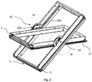
- a prior art roof window with a frame 1', a sash 2', a pane 3' and a hinge 10' is shown in Fig. 1 .
- Parts of the prior art roof window which are applicable also to a roof window according to the invention are described in Applicant's published European patent applications EP 2 770 146 A1 and EP 2 770 149 A1 to which reference is hereby explicitly made.
- the roof window is intended to be built into a surface, which is inclined with respect to the horizontal, typically a roof, and the window will in the following be referred to as roof window.
- a hinge connection between the frame 1' and the sash 2'.
- the hinge connection in Fig. 1 comprises a set of two prior art hinges, of which one hinge 10' is visible.
- the frame 1' and sash 2' is each formed by four members of which one frame side member 11' and one sash side member 21' are indicated.
- the sash 2' is openable with respect to the frame 1', as the sash 2' may be moved from a closed position, in which e.g.
- the sash side member 21' is substantially parallel with the frame side member 11', to an open position, in which the sash side member 21' forms an angle with the frame side member 11'.
- the sash 2' rotates about a hinge axis ⁇ ' situated at the hinge connection.
- the hinge axis ⁇ ' is located between a centre axis and the top of the roof window, preferably in the interval 1/3 to 2/3 of the distance between the centre axis and the top, most preferred substantially at 1/2 of the distance between the centre axis and the top.
- Other positions of the hinge axis is of course conceivable, for instance at the centre of the roof window.
- the operating device typically comprises a handle (not shown) connected with the sash bottom member and/or an operating and locking assembly including a ventilation flap at the sash top member with a lock mechanism to interact with a striking plate on the frame top member.
- the set of hinges 10' exerts a moment on the sash 2', and in combination with the force, and hence moment, exerted by the user operating the operating device, the moment resulting from the weight of the sash 2' and pane 3' is overcome, along with any frictional forces present. All in all, the opening operation entails that the sash 2' is moved from a closed position to an open position as represented by Fig.
- the sash plane forms an opening angle with the frame plane. Closing the window from the open position entails the opposite movement of the sash 2'. It is possible to position the sash 2' in a number of arbitrary opening positions, in which the sash 2' is held stable relative to the frame 1'. The sash 2' is also able to be rotated substantially through 180° to allow cleaning of the outside of the pane 3' from the inside of the building in which the roof window is installed.
- a first embodiment of a roof window according to the invention will be described in detail. Elements having the same or analogous function as in the prior art are denoted by the same reference numerals without the ' mark.
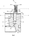
- the hinge 10 comprises a frame hinge part 100 and a sash hinge part 200 configured to assume an angle relative to the frame hinge part 100.
- the hinge 10 forms part of a set of hinges, of which the frame hinge part 100 of each hinge 10 is configured to be fastened to the frame side member 11 of the frame 1 of the roof window, at a location chosen to provide the desired position of the hinge axis ⁇ relative to the height direction of the roof window, i.e. parallel to the side members 11, 21 of the frame and sash, respectively, and the sash hinge part 200 is correspondingly configured to be fastened to the sash side member 21 as will be described in further detail below.
- the sash 2 and frame 1 each has an interior side 21i, 11i, respectively, adapted to face the interior, here indicated as an interior space 8, of the building in the mounted condition and an exterior side 21e, 11e, respectively adapted to face the exterior, here indicated as an exterior space 7, of the building in the mounted condition.
- Additional components and parts of relevance include an inward frame surface 11b and an interior frame surface 11i, and an outward sash surface 21b and an interior sash surface 21i.
- the inward frame surface 11b and the outward sash surface 21b delimit a gap 9 between the frame 1 and the sash 2.
- each hinge 10 of said set of hinges defines a hinge centre c.
- the hinge centre c represents the mid-point of the main operational parts of the hinge, applying to the geometry and/or weight.
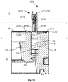
- each base plate 110, 210 has a predefined circumference cf, cs, respectively, as shown in Figs 3 and 4 .
- the hinge centre c is defined as the geometrical centre of the predefined circumference cf, cs of the base plate 110, 210 of one of, or both, the frame and sash hinge parts 100, 200.
- the hinge centre c of each hinge 10 is offset from the hinge axis ⁇ , and the set of hinges is arranged such that the hinge centre c of each hinge 10 is located to the exterior of the exterior side 21e, 11e of the sash 2 and frame 1 and the hinge axis ⁇ is located to the interior of the exterior side 21e, 11e of the sash 2 and frame 1.
- hinge components including a specific value of the offsetting of the particular hinge and combine with a suitable positioning of the hinge such that the hinge centre is located to the exterior of the sash and frame of the roof window, it is a prerequisite that the hinge axis ⁇ is located to the interior of the exterior side of the sash and frame.
- the distance between the hinge axis ⁇ and the hinge centre c lies in the range of 30 to 150 mm, preferably 45 to 120 mm, more preferably 60 to 90 mm.
- the distance is about 65 mm.
- the distance may be chosen in combination with suitable dimensions of the height of the base plate 110, 210 of the frame hinge part 100 and the sash hinge part 210, respectively.
- the height lies in the interval 40 to 80 mm, preferably 50 to 70 mm.
- the height of the base plate of the sash hinge part may be about 65 mm, somewhat larger than the height of the base plate of the frame hinge part which is typically about 55 mm.
- the general principles underlying the invention are applicable to all kinds of hinges in which it is possible to provide a hinge axis which is offset from the hinge centre.
- the hinge 10 makes use of the operational principles common to one very well-proven type of hinge, viz. the pivot hinge including a guidance on the frame hinge part cooperating with a slide rail on the sash hinge part.
- the pivot hinges are for instance disclosed in Applicant's EP 1 038 083 B1 and EP 1 781 883 B1 , and are very versatile as regards operational areas and adaptation of components. Examples of roof windows incorporating such adapted hinges are shown in Applicant's published European patent applications EP 2 770 146 A1 and EP 2 770 149 A1 .
- the pivot hinge 10 is mounted in such a way that the concavity of the guidance and the slide rail faces the interior 8 of the roof window to provide the offset hinge axis ⁇ at a more interior position than the set of hinges 10. That is, the pivot hinge is mounted in a reverse or upside-down position relative to what is standard.
- An alternative hinge is a pantograph hinge, in which the desired pattern of movements is provided by a linkage mechanism.
- hinges including linkage mechanisms are traditionally most often known from the furniture field, but such hinges are also well-known to use for roof windows.
- Prior art examples include Danish patent No. 114 321 , US patent No. 4,446,597 , and Applicant's European patents EP 22 657 B1 and EP 89 813 B1 .
- Such pantograph hinges also provide a hinge axis which is offset from the hinge centre. The same operation as described above and from here on is also true for the type of hinge described in the Applicant's international application published under WO 2017/076416 A1 .
- the pantograph hinge 1010 defines a movement pattern providing the offset hinge axis ⁇ at a more interior position than the set of hinges 1010. This too entails a reverse or upside-down positioning of the hinge.
- the hinge 10; 1010 is connected to the frame 1 and the sash 2 by means of first mounting means and second mounting means.
- the first mounting means comprises a first flange 140; 1140 in connection with the base plate 110; 1110 of the frame hinge part 100; 1100 and a second flange 150; 1150 in connection with the frame side member 11.
- the second mounting means comprises a first flange 240; 1240 in connection with the base plate 210; 1210 of the sash hinge part 200; 1200 and a second flange 250; 1250 in connection with the sash side member 21.
- connection between each first flange and the respective base plate may in principle be carried out in any suitable manner, but advantageously, and in the embodiments shown, the connection between the first flange 140, 240; 1140, 1240 and the respective base plate 110, 210; 1110, 1210 of the frame and sash hinge parts 100, 200; 1100, 1200 is integral.
- the respective base plate 110, 210; 1110, 1210 of the frame and sash hinge parts 100, 200; 1100, 1200 is substantially plane.
- the first flange 140; 1140 of the first mounting means is substantially parallel to the plane of the base plate 110; 1110 of the frame hinge part 100; 1100.
- the first flange 240 forms an angle relative to the respective base plate 210. This allows the hinge 10 to be positioned more to the outwards.
- the second flange 150; 1150 of the first mounting means in the first and second embodiments, and the second flange 1250 of the second mounting means of the second embodiment has an extension substantially parallel to the frame and sash plane, respectively.
- the second flange 150; 1150 of the first mounted means is connected to a recess 11c in the frame side member 11.
- these second flanges could alternatively be connected an exterior frame surface.
- the second flange 1250 of the second mounting means is connected to the exterior sash surface 21e of the sash side member. It is conceivable also to position this second flange 1250 in a recess.
- the second flange 250 of the second mounting means has an extension substantially perpendicular to the sash plane and is connected to the outward sash surface 21b.
- third mounting means are furthermore provided in addition to the first and second mounting means, said third mounting means here comprising a first flange 160 in connection with the base plate 110 of the frame hinge part 100, and a second flange 170 in connection with the frame side member 11.
- Corresponding further mounting means may also be present on the sash frame part.
Claims (13)
- Dachfenster, umfassend:einen Rahmen (1) mit mehreren Rahmenelementen (11), der eine Rahmenebene definiert und dazu ausgelegt ist, mit einer lasttragenden Struktur eines Dachs eines Gebäudes verbunden zu sein;einen Flügel (2) mit mehreren Flügelelementen (21), der eine Scheibe (3) trägt, die eine Flügelebene definiert; undeinen Satz von Scharnieren (10; 1010), die den Flügel (2) mit dem Rahmen (1) verbinden, um zu ermöglichen, dass die Flügelebene einen Winkel relativ zur Rahmenebene einnimmt, wobei jedes Scharnier (10; 1010) des Satzes von Scharnieren eine Scharniermitte (c) definiert und ein Rahmenscharnierteil (100; 1100), das mit einem Rahmenseitenelement (11) in Verbindung steht, sowie ein Flügelscharnierteil (200; 1200), das mit einem Flügelseitenelement (21) in Verbindung steht und dazu gestaltet ist, einen Winkel relativ zum Rahmenscharnierteil (100; 1100) einzunehmen, beinhaltet, wobei das Rahmenscharnierteil (100; 1100) und das Flügelscharnierteil (200; 1200) jedes eine Grundplatte (110; 210) umfassen, die im Wesentlichen eben und parallel zueinander sind, wobei der Satz von Scharnieren (10; 1010) eine Scharnierachse (a) definiert,wobei der Flügel (2) und der Rahmen (1) jeder eine Innenseite (21i, 11i) aufweisen, die dazu ausgelegt ist, im montierten Zustand dem Inneren (8) des Gebäudes zugewandt zu sein, und eine Außenseite (21e, 11e), die dazu ausgelegt ist, im montierten Zustand dem Äußeren (7) des Gebäudes zugewandt zu sein,wobei jede Grundplatte (110, 210; 1110, 1210) einen vorbestimmten Umfang (cf, cs) aufweist, wobei die Scharniermitte (c) als die geometrische Mitte des vorbestimmten Umfangs (cs) der Grundplatte (210; 1210) des Flügelscharnierteils (200; 1200) definiert ist,wobeidie Scharniermitte (c) jedes Scharniers (10; 1010) des Satzes von Scharnieren zur Scharnierachse (α) versetzt ist,die Scharnierachse (α) zum Inneren der Außenseite (21e, 11e) des Flügels (2) und des Rahmens (1) hin angeordnet ist,und der Abstand zwischen der Scharnierachse (α) und der Scharniermitte (c) im Bereich von 30 bis 150 mm, vorzugsweise 45 bis 120 mm, besonders vorzugsweise 60 bis 90 mm, liegt, sodass die Scharnierachse (α) in der Nähe des Schwerpunkts des die Scheibe beinhaltenden Flügels liegt,dadurch gekennzeichnet, dass der Satz von Scharnieren so angeordnet ist, dass die Scharniermitte (c) jedes Scharniers (10; 1010) zum Äußeren der Außenseite (21e, 11e) des Flügels (2) und des Rahmens (1) hin angeordnet ist.
- Dachfenster nach Anspruch 1, wobei die Höhe der Grundplatte (110, 210; 1100, 1210) des Rahmenscharnierteils (100) und des Flügelscharnierteils (210), jeweils im Bereich von 40 bis 80 mm, vorzugsweise 50 bis 70 mm liegt.
- Dachfenster nach einem der vorangehenden Ansprüche, wobei jedes Scharnier des Satzes von Scharnieren ein Drehscharnier (10) mit einer Führung am Rahmenscharnierteil (100) umfasst, das mit einer Gleitschiene am Flügelscharnierteil (200) zusammenwirkt und so montiert ist, dass die Konkavität der Führung und der Gleitschiene dem Inneren (8) des Dachfensters zugewandt ist, um die versetzte Scharnierachse (α) an einer Position bereitzustellen, die weiter innen liegt als der Satz von Scharnieren (10) .
- Dachfenster nach einem der Ansprüche 1 bis 2, wobei jedes Scharnier des Satzes von Scharnieren ein Scherenscharnier (1010) umfasst, das zumindest eine Verbindung aufweist und ein Bewegungsmuster definiert, das die versetzte Scharnierachse (α) Position bereitstellt, die weiter innen liegt als der Satz von Scharnieren (1010).
- Dachfenster nach einem der vorangehenden Ansprüche, wobei das Scharnier (10; 1010) mit Hilfe eines ersten Befestigungsmittels (140, 150; 1140, 1150) und eines zweiten Befestigungsmittels (240, 250; 1240, 1250) am Rahmen (1) und am Flügel (2) befestigt ist.
- Dachfenster nach Anspruch 5, wobei das erste Befestigungsmittel einen mit der Grundplatte (110; 1110) des Rahmenscharnierteils (100; 1100) in Verbindung stehenden ersten Flansch (140; 1140) und einen mit dem Rahmenseitenelement (11) in Verbindung stehenden zweiten Flansch (150; 1150) umfasst und wobei das zweite Befestigungsmittel einen mit der Grundplatte (210; 1210) des Flügelscharnierteils (200; 1200) in Verbindung stehenden ersten Flansch (240; 1240) und einen mit dem Flügelseitenelement (21) in Verbindung stehenden zweiten Flansch (250; 1250) umfasst.
- Dachfenster nach Anspruch 6, wobei die Verbindung zwischen dem ersten Flansch (140, 240; 1140, 1240) und der jeweiligen Grundplatte (110, 210; 1110, 1210) des Rahmens und der Flügelscharnierteile (100, 200; 1100, 1200) stoffschlüssig ist.
- Dachfenster nach Anspruch 6 oder 7, wobei der erste Flansch (140; 1140, 1240) im Wesentlichen parallel zur Ebene der jeweiligen Grundplatte (110, 210; 1110, 1210) ist.
- Dachfenster nach Anspruch 6 oder 9, wobei der erste Flansch (240) einen Winkel relativ zur jeweiligen Grundplatte (210) ausbildet.
- Dachfenster nach einem der Ansprüche 6 bis 9, wobei der zweite Flansch (150; 1150, 1250) eine Erstreckung aufweist, die im Wesentlichen parallel zur Rahmen- bzw. Flügelebene ist.
- Dachfenster nach Anspruch 10, wobei der zweite Flansch (150; 1150, 1250) mit einer äußeren Rahmenfläche bzw. äußeren Flügelfläche (21e) oder mit einer Ausnehmung (11c) im Rahmenseitenelement (11) bzw. im Flügelseitenelement verbunden ist.
- Dachfenster nach einem der Ansprüche 6 bis 9, wobei der zweite Flansch (250) eine Erstreckung aufweist, die im Wesentlichen parallel zur Rahmen- bzw. Flügelebene ist und mit einer inneren Rahmenfläche oder äußeren Flügelfläche (21b) verbunden ist.
- Dachfenster nach einem der Ansprüche 5 bis 12, wobei zusätzlich zum ersten und zweiten Befestigungsmittel ein drittes Befestigungsmittel (160, 170) bereitgestellt ist, wobei das Befestigungsmittel vorzugsweise einen mit der Grundplatte (110) des Rahmenscharnierteils (100) bzw. des Flügelscharnierteils in Verbindung stehenden ersten Flansch (160) und einen mit dem Rahmenseitenelement (11) bzw. dem Flügelseitenelement in Verbindung stehenden zweiten Flansch (170) umfasst.
Priority Applications (1)
| Application Number | Priority Date | Filing Date | Title |
|---|---|---|---|
| PL17192608T PL3299536T3 (pl) | 2016-09-23 | 2017-09-22 | Okno dachowe zawierające zestaw zawiasów z ulepszonym schematem ruchu |
Applications Claiming Priority (1)
| Application Number | Priority Date | Filing Date | Title |
|---|---|---|---|
| DKPA201670757A DK180302B1 (en) | 2016-09-23 | 2016-09-23 | A roof window including a set of hinges with improved movement pattern |
Publications (2)
| Publication Number | Publication Date |
|---|---|
| EP3299536A1 EP3299536A1 (de) | 2018-03-28 |
| EP3299536B1 true EP3299536B1 (de) | 2019-12-11 |
Family
ID=59997090
Family Applications (1)
| Application Number | Title | Priority Date | Filing Date |
|---|---|---|---|
| EP17192608.2A Active EP3299536B1 (de) | 2016-09-23 | 2017-09-22 | Dachfenster mit einem satz von scharnieren mit verbessertem bewegungsmuster |
Country Status (3)
| Country | Link |
|---|---|
| EP (1) | EP3299536B1 (de) |
| DK (1) | DK180302B1 (de) |
| PL (1) | PL3299536T3 (de) |
Citations (2)
| Publication number | Priority date | Publication date | Assignee | Title |
|---|---|---|---|---|
| EP2770146A1 (de) * | 2013-02-22 | 2014-08-27 | VKR Holding A/S | Verbesserte Drehscharnierfassung und ein Dachfenster mit solch einer Scharnierfassung |
| EP2843148A1 (de) * | 2013-08-28 | 2015-03-04 | FAKRO PP Sp. z o.o. | Einbausystem für ein Dachfenster in eine Dachfläche |
Family Cites Families (14)
| Publication number | Priority date | Publication date | Assignee | Title |
|---|---|---|---|---|
| US2885745A (en) * | 1956-06-01 | 1959-05-12 | Evers & Co Aktiebolag | Window structure |
| DK114321B (da) * | 1966-10-07 | 1969-06-16 | Bierlich J H | Hængsel. |
| DE1969508U (de) * | 1967-07-20 | 1967-09-28 | E L Hirz K G | Schraegdachfenster. |
| NO122890B (de) * | 1969-05-19 | 1971-08-30 | D Vaa | |
| DK144771C (da) * | 1979-07-10 | 1982-10-25 | V B K Rasmussen | Haengselbeslag til vippevinduer,navnlig skraat indbyggede tagvinduer |
| DK146397C (da) * | 1981-07-03 | 1984-03-05 | Rasmussen Holding As V Kann | Haengselbeslag til skraat indbyggede vippevinduer med udvendige daekskinner |
| DK147861C (da) * | 1982-03-22 | 1985-07-22 | Rasmussen Holding As V Kann | Haengsel til vippevinduer, navnlig til indbygning i en skraa tagflade |
| DK176024B1 (da) | 1997-11-11 | 2005-12-19 | Vkr Holding As | Hængselbeslag til et vippevindue |
| CN2795390Y (zh) | 2004-07-02 | 2006-07-12 | Vkr控股公司 | 铰链装置 |
| KR101410775B1 (ko) * | 2006-09-20 | 2014-06-23 | 오일레스 에코 가부시키가이샤 | 자연 환기창 |
| DK177808B1 (en) * | 2013-02-22 | 2014-07-21 | Vkr Holding As | A roof window having an improved lifting device and hinge connection |
| PL236003B1 (pl) * | 2013-08-28 | 2020-11-30 | Fakro Pp Spolka Z Ograniczona Odpowiedzialnoscia | Ościeżnica z okuciem dla okna dachowego |
| PL228463B1 (pl) * | 2014-03-17 | 2018-03-30 | Fakro Pp Spolka Z Ograniczona Odpowiedzialnoscia | Okno dachowe z zawiasem o podwyzszonej odpornosci na włamanie |
| DK179269B1 (en) | 2015-11-06 | 2018-03-19 | Vkr Holding As | A hinge for a roof window, and a roof window including a set of such hinges |
-
2016
- 2016-09-23 DK DKPA201670757A patent/DK180302B1/en not_active IP Right Cessation
-
2017
- 2017-09-22 PL PL17192608T patent/PL3299536T3/pl unknown
- 2017-09-22 EP EP17192608.2A patent/EP3299536B1/de active Active
Patent Citations (2)
| Publication number | Priority date | Publication date | Assignee | Title |
|---|---|---|---|---|
| EP2770146A1 (de) * | 2013-02-22 | 2014-08-27 | VKR Holding A/S | Verbesserte Drehscharnierfassung und ein Dachfenster mit solch einer Scharnierfassung |
| EP2843148A1 (de) * | 2013-08-28 | 2015-03-04 | FAKRO PP Sp. z o.o. | Einbausystem für ein Dachfenster in eine Dachfläche |
Also Published As
| Publication number | Publication date |
|---|---|
| PL3299536T3 (pl) | 2020-05-18 |
| EP3299536A1 (de) | 2018-03-28 |
| DK180302B1 (en) | 2020-10-20 |
| DK201670757A1 (en) | 2018-04-16 |
Similar Documents
| Publication | Publication Date | Title |
|---|---|---|
| US20050011049A1 (en) | Egress 4-bar hinge assembly | |
| EP3040500B1 (de) | Verborgenes scharnier für ein schwenkbares fenster oder eine schwenkbare tür und damit ausgestattetes fenster | |
| KR102010377B1 (ko) | 회동식 창호시스템의 창호스테이바 유닛 | |
| CA2285835C (en) | Hinge mechanism | |
| EP3299536B1 (de) | Dachfenster mit einem satz von scharnieren mit verbessertem bewegungsmuster | |
| US6513194B2 (en) | Pivot connection adjustment assembly | |
| JPH0238681A (ja) | 窓,ドア等の開閉用継手金物 | |
| JP4876813B2 (ja) | 自然換気窓 | |
| JP7076674B2 (ja) | 脱出ドアユニット | |
| PL201187B1 (pl) | Zestaw okuć do okna lub drzwi oraz okno lub drzwi | |
| JP5385645B2 (ja) | 上げ下げ窓 | |
| EP2607578A1 (de) | Sperranordnung und Schließblech | |
| KR102364758B1 (ko) | 환기 기능 및 수평 밀착 기능을 갖는 창호 조립체 | |
| US20060021192A1 (en) | Hinge device for a door leaf | |
| EP3290614B1 (de) | Dachfenster mit verbesserten isolierungseigenschaften und mit einem satz an scharnieren | |
| EP3348738B1 (de) | Dual-function dachfenster mit einer dachfensterflügelmontageanordnung | |
| EP3842610B1 (de) | Scharnieranordnung für ein dachfenster mit verbesserter bedienbarkeit | |
| CN215255445U (zh) | 一种滑撑铰链 | |
| EP3578738B1 (de) | Betriebsmechanismus für eine hebe-schiebetür und eine mit einem solchen mechanismus ausgestattete hebe-schiebetür | |
| EP3348763B1 (de) | Zwischenmontage-montage für ein doppelfunktionsdachfenster | |
| EP4098835A1 (de) | Ein fenstersystem | |
| EP2211009B1 (de) | Nach außen öffnende Fenster | |
| JP2002242517A (ja) | 折 戸 | |
| JP2591639Y2 (ja) | 建具枠の補強構造 | |
| JP5465141B2 (ja) | サッシ |
Legal Events
| Date | Code | Title | Description |
|---|---|---|---|
| PUAI | Public reference made under article 153(3) epc to a published international application that has entered the european phase |
Free format text: ORIGINAL CODE: 0009012 |
|
| STAA | Information on the status of an ep patent application or granted ep patent |
Free format text: STATUS: THE APPLICATION HAS BEEN PUBLISHED |
|
| AK | Designated contracting states |
Kind code of ref document: A1 Designated state(s): AL AT BE BG CH CY CZ DE DK EE ES FI FR GB GR HR HU IE IS IT LI LT LU LV MC MK MT NL NO PL PT RO RS SE SI SK SM TR |
|
| AX | Request for extension of the european patent |
Extension state: BA ME |
|
| TPAC | Observations filed by third parties |
Free format text: ORIGINAL CODE: EPIDOSNTIPA |
|
| STAA | Information on the status of an ep patent application or granted ep patent |
Free format text: STATUS: REQUEST FOR EXAMINATION WAS MADE |
|
| 17P | Request for examination filed |
Effective date: 20180928 |
|
| RBV | Designated contracting states (corrected) |
Designated state(s): AL AT BE BG CH CY CZ DE DK EE ES FI FR GB GR HR HU IE IS IT LI LT LU LV MC MK MT NL NO PL PT RO RS SE SI SK SM TR |
|
| STAA | Information on the status of an ep patent application or granted ep patent |
Free format text: STATUS: EXAMINATION IS IN PROGRESS |
|
| 17Q | First examination report despatched |
Effective date: 20181204 |
|
| GRAP | Despatch of communication of intention to grant a patent |
Free format text: ORIGINAL CODE: EPIDOSNIGR1 |
|
| STAA | Information on the status of an ep patent application or granted ep patent |
Free format text: STATUS: GRANT OF PATENT IS INTENDED |
|
| INTG | Intention to grant announced |
Effective date: 20190702 |
|
| GRAS | Grant fee paid |
Free format text: ORIGINAL CODE: EPIDOSNIGR3 |
|
| GRAA | (expected) grant |
Free format text: ORIGINAL CODE: 0009210 |
|
| STAA | Information on the status of an ep patent application or granted ep patent |
Free format text: STATUS: THE PATENT HAS BEEN GRANTED |
|
| AK | Designated contracting states |
Kind code of ref document: B1 Designated state(s): AL AT BE BG CH CY CZ DE DK EE ES FI FR GB GR HR HU IE IS IT LI LT LU LV MC MK MT NL NO PL PT RO RS SE SI SK SM TR |
|
| REG | Reference to a national code |
Ref country code: GB Ref legal event code: FG4D |
|
| REG | Reference to a national code |
Ref country code: CH Ref legal event code: EP |
|
| REG | Reference to a national code |
Ref country code: AT Ref legal event code: REF Ref document number: 1212316 Country of ref document: AT Kind code of ref document: T Effective date: 20191215 |
|
| REG | Reference to a national code |
Ref country code: DE Ref legal event code: R096 Ref document number: 602017009551 Country of ref document: DE |
|
| REG | Reference to a national code |
Ref country code: IE Ref legal event code: FG4D |
|
| REG | Reference to a national code |
Ref country code: NL Ref legal event code: MP Effective date: 20191211 |
|
| REG | Reference to a national code |
Ref country code: LT Ref legal event code: MG4D |
|
| PG25 | Lapsed in a contracting state [announced via postgrant information from national office to epo] |
Ref country code: SE Free format text: LAPSE BECAUSE OF FAILURE TO SUBMIT A TRANSLATION OF THE DESCRIPTION OR TO PAY THE FEE WITHIN THE PRESCRIBED TIME-LIMIT Effective date: 20191211 Ref country code: LV Free format text: LAPSE BECAUSE OF FAILURE TO SUBMIT A TRANSLATION OF THE DESCRIPTION OR TO PAY THE FEE WITHIN THE PRESCRIBED TIME-LIMIT Effective date: 20191211 Ref country code: GR Free format text: LAPSE BECAUSE OF FAILURE TO SUBMIT A TRANSLATION OF THE DESCRIPTION OR TO PAY THE FEE WITHIN THE PRESCRIBED TIME-LIMIT Effective date: 20200312 Ref country code: NO Free format text: LAPSE BECAUSE OF FAILURE TO SUBMIT A TRANSLATION OF THE DESCRIPTION OR TO PAY THE FEE WITHIN THE PRESCRIBED TIME-LIMIT Effective date: 20200311 Ref country code: BG Free format text: LAPSE BECAUSE OF FAILURE TO SUBMIT A TRANSLATION OF THE DESCRIPTION OR TO PAY THE FEE WITHIN THE PRESCRIBED TIME-LIMIT Effective date: 20200311 Ref country code: LT Free format text: LAPSE BECAUSE OF FAILURE TO SUBMIT A TRANSLATION OF THE DESCRIPTION OR TO PAY THE FEE WITHIN THE PRESCRIBED TIME-LIMIT Effective date: 20191211 Ref country code: FI Free format text: LAPSE BECAUSE OF FAILURE TO SUBMIT A TRANSLATION OF THE DESCRIPTION OR TO PAY THE FEE WITHIN THE PRESCRIBED TIME-LIMIT Effective date: 20191211 |
|
| PG25 | Lapsed in a contracting state [announced via postgrant information from national office to epo] |
Ref country code: HR Free format text: LAPSE BECAUSE OF FAILURE TO SUBMIT A TRANSLATION OF THE DESCRIPTION OR TO PAY THE FEE WITHIN THE PRESCRIBED TIME-LIMIT Effective date: 20191211 Ref country code: RS Free format text: LAPSE BECAUSE OF FAILURE TO SUBMIT A TRANSLATION OF THE DESCRIPTION OR TO PAY THE FEE WITHIN THE PRESCRIBED TIME-LIMIT Effective date: 20191211 |
|
| PG25 | Lapsed in a contracting state [announced via postgrant information from national office to epo] |
Ref country code: AL Free format text: LAPSE BECAUSE OF FAILURE TO SUBMIT A TRANSLATION OF THE DESCRIPTION OR TO PAY THE FEE WITHIN THE PRESCRIBED TIME-LIMIT Effective date: 20191211 |
|
| PG25 | Lapsed in a contracting state [announced via postgrant information from national office to epo] |
Ref country code: PT Free format text: LAPSE BECAUSE OF FAILURE TO SUBMIT A TRANSLATION OF THE DESCRIPTION OR TO PAY THE FEE WITHIN THE PRESCRIBED TIME-LIMIT Effective date: 20200506 Ref country code: CZ Free format text: LAPSE BECAUSE OF FAILURE TO SUBMIT A TRANSLATION OF THE DESCRIPTION OR TO PAY THE FEE WITHIN THE PRESCRIBED TIME-LIMIT Effective date: 20191211 Ref country code: NL Free format text: LAPSE BECAUSE OF FAILURE TO SUBMIT A TRANSLATION OF THE DESCRIPTION OR TO PAY THE FEE WITHIN THE PRESCRIBED TIME-LIMIT Effective date: 20191211 Ref country code: RO Free format text: LAPSE BECAUSE OF FAILURE TO SUBMIT A TRANSLATION OF THE DESCRIPTION OR TO PAY THE FEE WITHIN THE PRESCRIBED TIME-LIMIT Effective date: 20191211 Ref country code: EE Free format text: LAPSE BECAUSE OF FAILURE TO SUBMIT A TRANSLATION OF THE DESCRIPTION OR TO PAY THE FEE WITHIN THE PRESCRIBED TIME-LIMIT Effective date: 20191211 Ref country code: ES Free format text: LAPSE BECAUSE OF FAILURE TO SUBMIT A TRANSLATION OF THE DESCRIPTION OR TO PAY THE FEE WITHIN THE PRESCRIBED TIME-LIMIT Effective date: 20191211 |
|
| PG25 | Lapsed in a contracting state [announced via postgrant information from national office to epo] |
Ref country code: SM Free format text: LAPSE BECAUSE OF FAILURE TO SUBMIT A TRANSLATION OF THE DESCRIPTION OR TO PAY THE FEE WITHIN THE PRESCRIBED TIME-LIMIT Effective date: 20191211 Ref country code: SK Free format text: LAPSE BECAUSE OF FAILURE TO SUBMIT A TRANSLATION OF THE DESCRIPTION OR TO PAY THE FEE WITHIN THE PRESCRIBED TIME-LIMIT Effective date: 20191211 Ref country code: IS Free format text: LAPSE BECAUSE OF FAILURE TO SUBMIT A TRANSLATION OF THE DESCRIPTION OR TO PAY THE FEE WITHIN THE PRESCRIBED TIME-LIMIT Effective date: 20200411 |
|
| REG | Reference to a national code |
Ref country code: DE Ref legal event code: R097 Ref document number: 602017009551 Country of ref document: DE |
|
| REG | Reference to a national code |
Ref country code: AT Ref legal event code: MK05 Ref document number: 1212316 Country of ref document: AT Kind code of ref document: T Effective date: 20191211 |
|
| PLBE | No opposition filed within time limit |
Free format text: ORIGINAL CODE: 0009261 |
|
| STAA | Information on the status of an ep patent application or granted ep patent |
Free format text: STATUS: NO OPPOSITION FILED WITHIN TIME LIMIT |
|
| PG25 | Lapsed in a contracting state [announced via postgrant information from national office to epo] |
Ref country code: DK Free format text: LAPSE BECAUSE OF FAILURE TO SUBMIT A TRANSLATION OF THE DESCRIPTION OR TO PAY THE FEE WITHIN THE PRESCRIBED TIME-LIMIT Effective date: 20191211 |
|
| 26N | No opposition filed |
Effective date: 20200914 |
|
| PG25 | Lapsed in a contracting state [announced via postgrant information from national office to epo] |
Ref country code: AT Free format text: LAPSE BECAUSE OF FAILURE TO SUBMIT A TRANSLATION OF THE DESCRIPTION OR TO PAY THE FEE WITHIN THE PRESCRIBED TIME-LIMIT Effective date: 20191211 Ref country code: SI Free format text: LAPSE BECAUSE OF FAILURE TO SUBMIT A TRANSLATION OF THE DESCRIPTION OR TO PAY THE FEE WITHIN THE PRESCRIBED TIME-LIMIT Effective date: 20191211 |
|
| PG25 | Lapsed in a contracting state [announced via postgrant information from national office to epo] |
Ref country code: IT Free format text: LAPSE BECAUSE OF FAILURE TO SUBMIT A TRANSLATION OF THE DESCRIPTION OR TO PAY THE FEE WITHIN THE PRESCRIBED TIME-LIMIT Effective date: 20191211 |
|
| REG | Reference to a national code |
Ref country code: CH Ref legal event code: PL |
|
| REG | Reference to a national code |
Ref country code: BE Ref legal event code: MM Effective date: 20200930 |
|
| PG25 | Lapsed in a contracting state [announced via postgrant information from national office to epo] |
Ref country code: LU Free format text: LAPSE BECAUSE OF NON-PAYMENT OF DUE FEES Effective date: 20200922 |
|
| PG25 | Lapsed in a contracting state [announced via postgrant information from national office to epo] |
Ref country code: FR Free format text: LAPSE BECAUSE OF NON-PAYMENT OF DUE FEES Effective date: 20200930 |
|
| PG25 | Lapsed in a contracting state [announced via postgrant information from national office to epo] |
Ref country code: CH Free format text: LAPSE BECAUSE OF NON-PAYMENT OF DUE FEES Effective date: 20200930 Ref country code: BE Free format text: LAPSE BECAUSE OF NON-PAYMENT OF DUE FEES Effective date: 20200930 Ref country code: LI Free format text: LAPSE BECAUSE OF NON-PAYMENT OF DUE FEES Effective date: 20200930 Ref country code: IE Free format text: LAPSE BECAUSE OF NON-PAYMENT OF DUE FEES Effective date: 20200922 |
|
| GBPC | Gb: european patent ceased through non-payment of renewal fee |
Effective date: 20210922 |
|
| PG25 | Lapsed in a contracting state [announced via postgrant information from national office to epo] |
Ref country code: TR Free format text: LAPSE BECAUSE OF FAILURE TO SUBMIT A TRANSLATION OF THE DESCRIPTION OR TO PAY THE FEE WITHIN THE PRESCRIBED TIME-LIMIT Effective date: 20191211 Ref country code: MT Free format text: LAPSE BECAUSE OF FAILURE TO SUBMIT A TRANSLATION OF THE DESCRIPTION OR TO PAY THE FEE WITHIN THE PRESCRIBED TIME-LIMIT Effective date: 20191211 Ref country code: CY Free format text: LAPSE BECAUSE OF FAILURE TO SUBMIT A TRANSLATION OF THE DESCRIPTION OR TO PAY THE FEE WITHIN THE PRESCRIBED TIME-LIMIT Effective date: 20191211 |
|
| PG25 | Lapsed in a contracting state [announced via postgrant information from national office to epo] |
Ref country code: MK Free format text: LAPSE BECAUSE OF FAILURE TO SUBMIT A TRANSLATION OF THE DESCRIPTION OR TO PAY THE FEE WITHIN THE PRESCRIBED TIME-LIMIT Effective date: 20191211 Ref country code: MC Free format text: LAPSE BECAUSE OF FAILURE TO SUBMIT A TRANSLATION OF THE DESCRIPTION OR TO PAY THE FEE WITHIN THE PRESCRIBED TIME-LIMIT Effective date: 20191211 |
|
| PG25 | Lapsed in a contracting state [announced via postgrant information from national office to epo] |
Ref country code: GB Free format text: LAPSE BECAUSE OF NON-PAYMENT OF DUE FEES Effective date: 20210922 |
|
| PGFP | Annual fee paid to national office [announced via postgrant information from national office to epo] |
Ref country code: PL Payment date: 20230816 Year of fee payment: 7 Ref country code: DE Payment date: 20230802 Year of fee payment: 7 |