EP3290614B1 - Dachfenster mit verbesserten isolierungseigenschaften und mit einem satz an scharnieren - Google Patents
Dachfenster mit verbesserten isolierungseigenschaften und mit einem satz an scharnieren Download PDFInfo
- Publication number
- EP3290614B1 EP3290614B1 EP17189065.0A EP17189065A EP3290614B1 EP 3290614 B1 EP3290614 B1 EP 3290614B1 EP 17189065 A EP17189065 A EP 17189065A EP 3290614 B1 EP3290614 B1 EP 3290614B1
- Authority
- EP
- European Patent Office
- Prior art keywords
- frame
- hinge
- sash
- roof window
- recess
- Prior art date
- Legal status (The legal status is an assumption and is not a legal conclusion. Google has not performed a legal analysis and makes no representation as to the accuracy of the status listed.)
- Active
Links
- 238000009413 insulation Methods 0.000 title description 7
- 230000005484 gravity Effects 0.000 claims description 4
- 230000008901 benefit Effects 0.000 description 4
- 238000001816 cooling Methods 0.000 description 4
- 238000009434 installation Methods 0.000 description 4
- 230000001419 dependent effect Effects 0.000 description 2
- 230000006872 improvement Effects 0.000 description 2
- 241000326087 Mayawa Species 0.000 description 1
- 230000006978 adaptation Effects 0.000 description 1
- 230000015572 biosynthetic process Effects 0.000 description 1
- 238000005253 cladding Methods 0.000 description 1
- 230000000694 effects Effects 0.000 description 1
- 239000000463 material Substances 0.000 description 1
- 230000007246 mechanism Effects 0.000 description 1
- 230000002093 peripheral effect Effects 0.000 description 1
- 230000007704 transition Effects 0.000 description 1
- 238000009423 ventilation Methods 0.000 description 1
- XLYOFNOQVPJJNP-UHFFFAOYSA-N water Substances O XLYOFNOQVPJJNP-UHFFFAOYSA-N 0.000 description 1
Images


Classifications
-
- E—FIXED CONSTRUCTIONS
- E04—BUILDING
- E04D—ROOF COVERINGS; SKY-LIGHTS; GUTTERS; ROOF-WORKING TOOLS
- E04D13/00—Special arrangements or devices in connection with roof coverings; Protection against birds; Roof drainage ; Sky-lights
- E04D13/03—Sky-lights; Domes; Ventilating sky-lights
- E04D13/035—Sky-lights; Domes; Ventilating sky-lights characterised by having movable parts
- E04D13/0351—Sky-lights; Domes; Ventilating sky-lights characterised by having movable parts the parts pivoting about a fixed axis
- E04D13/0354—Sky-lights; Domes; Ventilating sky-lights characterised by having movable parts the parts pivoting about a fixed axis the parts being flat
Definitions
- the present invention relates to a roof window comprising a sash and a frame, each of the sash and the frame having two side members, a top member and a bottom member, and delimiting a frame opening and a sash opening, respectively, said sash carrying a pane and being connected to the frame via a hinge device including a pair of hinges defining a hinge axis, said frame being adapted to be connected to a load-bearing structure of a roof of a building, in which the pane has an exterior surface and an interior surface, and the sash and frame each has an interior side adapted to face the interior of the building in the mounted condition and an exterior side adapted to face the exterior of the building in the mounted condition, wherein the pair of hinges are arranged on either side of the pane between the frame and the sash, and in which the frame comprises a frame recess facing the sash and in which at least part of each hinge is arranged, the frame recess having a frame recess depth and a
- Roof windows may be provided in a number of varieties and include more or less complicated structures in order to allow opening of the sash and to fulfil other functions, and yet provide an airtight structure with satisfactory thermal properties.
- a common issue with windows in general is how to keep them sufficiently tight and insulating from the ambient. Therefore, a number of factors have been identified in order to improve the thermal properties.
- certain elements used in a window installation serve as a cooling bridge, and thus transfer the heat from one side of the window to the other, i.e. allows a heat transfer between the ambience and the interior of a building.
- An attempt at overcoming this issue can be found in for example Applicant's European patent No.
- a roof window of the kind mentioned in the introduction is found in Applicant's European patent No. EP 2748391 B1 .
- a roof window according to the preamble of claim 1 is further known from WO 2010/088904 A1 .
- this and further objects are met by the provision of a roof window according to the preamble of claim 1 which is furthermore characterised in that the frame recess is provided with such a frame recess width that at least 60% of the width of each hinge is arranged in the frame recess.
- the effect of the cooling bridges is reduced while still retaining the advantages of a hinge positioned in close proximity to the frame-sash interface.
- a hinge By providing the hinge in a relatively wide recess in the frame it allows the hinge to be located as much as possible within the frame, but yet isolated from the interior.
- Such a recess may AWA#137524 for instance extend partially through the frame and house the hinge, seen from the exterior. In that way, it is ensured that the hinge does not come in direct contact with any of the interior, and thus not transfer any of the ambient temperature to the interior.
- the remainder of the material of the frame serves as insulation between the hinge and the interior. This structure contributes to a better insulation since a majority part of the hinge is arranged inside the frame, and thus away from the ambient.
- At least 80% of the width of each hinge is arranged in the frame recess. This improves the thermal properties even further.
- the remaining part of the width of the hinge is arranged within a sash recess of the sash and/or in a gap formed between the frame and the sash. In this way, the hinge may be hidden as much as possible within the frame and sash.
- the recess in the sash may be formed to allow connection of the hinge to the sash.
- substantially the entire hinge is arranged in said frame recess.
- the hinge intrudes as little as possible in the sash, allowing the sash to be configured as narrow as possible.
- substantially entire hinge it is meant as much as allowable.
- the sash may however include a connection to the hinge which, for evident reasons, may not be enclosed within the recess of the frame.
- the frame recess is provided with such a depth that at least 60% of the depth of the hinge is arranged therein such that the hinge extends at least partially to the interior of the exterior surface of the pane, as seen from a plane perpendicular to the pane.
- the frame recess is provided with such a frame recess depth that substantially the entire hinge is arranged in said frame recess.
- the pane is arranged relative to the frame such that an outward edge of the pane facing the frame is arranged at a distance from an inner edge of the frame facing the sash of not more than 50% of the width of the hinge, preferably less than 25%, and most preferably between 0-15%.
- a slim sash is provided, and it is possible to configure the sash and the frame such that the frame edge and the pane edge almost coincide.
- a width of the gap between the sash and the frame is as small as possible.
- the exterior surface of the pane is substantially flush with an exterior surface of the frame. This is an advantage since the exterior of the window may become as flat as possible. A low profile altogether helps the window to stay cleaner and drained since there may be fewer protrusions that may catch dirt and water.
- the frame recess is provided in an exterior surface of the frame.
- the frame recess faces the exterior, in addition to facing the sash, which in turn provides for the least restrictions on the configuration of other parts of the roof window in order to allow unimpeded movement of the sash relative to the frame during opening and closing of the roof window.
- the pair of hinges is located such that the hinge axis is positioned to the interior of the interior surface of the pane. This is an advantage in that the hinge axis is positioned close to, or even coinciding with the centre of gravity of the sash including the pane.
- the configuration of the hinge device of the roof window according to the invention may be chosen in any suitable way, as the formation of the roof window allows for an increased overall flexibility, within the limits defined by the claims.
- the hinge is a pivot hinge including a hinge pin defining an axis of rotation substantially coinciding with hinge axis of the roof window.
- the hinge is a pivot hinge including a guidance and a slide rail defining an axis of rotation offset from the hinge centre.
- This particular type of pivot hinge is very well-known and is considered as constituting more or less "industry standard" within the field of roof windows.
- the pivot hinge has a set of predefined dimensions, of which at least two dimensions are smaller than the corresponding dimensions of a standard pivot hinge.
- each hinge of said pair of hinges comprises a sash hinge part and a frame hinge part, of substantially equal width. This is advantageous in particular from the point of mounting.
- a window generally designated 1 comprises a sash 3 carrying a glazing in the form of a pane 5 and a frame 4.
- the window is intended to be built into a surface, which is inclined with respect to the horizontal, typically a roof, and the window will in the following be referred to as a roof window 1.
- a hinge device 2 At a position between the top and centre of the window, there is a hinge device 2 to provide connection between the frame 4 and the sash 3.
- the hinge device 2 of the prior art roof window shown in Fig. 1 comprises a set of two traditional pivot hinges.
- the frame 4 and sash 3 each has two side members, a top member and a bottom member, and delimiting a frame opening and a sash opening, respectively.
- the sash 3 is openable with respect to the frame 4, as the sash 3 may be moved from a closed position, in which the sash side members are substantially parallel with the frame side members, to an open position, in which the sash side members form an angle with the frame side members.
- the sash 3 rotates about a hinge axis ⁇ situated at or near the hinge device 2.
- the hinge axis ⁇ is located between a centre axis and the top of the roof window.
- pivot hinges such as they are for instance disclosed in Applicant's EP 1 038 083 B1 and EP 1 781 883 B1 , which are very versatile as regards operational areas and adaptation of components. Examples of roof windows incorporating such adapted hinges are shown in Applicant's published European patent applications EP 2 770 146 A1 and EP 2 770 149 A1 . From a closed position, the user operates the operating device of the window.
- the operating device typically comprises a handle (not shown) connected with the sash bottom member and/or an operating and locking assembly including a ventilation flap at the sash top member with a lock mechanism to interact with a striking plate on the frame top member.
- the roof window comprises a covering, including flashing members (not shown), cladding and covering elements of which a frame side covering element and sash side covering element are indicated by reference numeral 10.
- the parts of the covering of the prior art roof window are connected to the frame and the sash, and to the hinge in a hinge and covering assembly as described in detail in the above-mentioned embodiment of EP 2 751 354 B1 .
- FIG. 1 a first embodiment of the roof window 1 according to the invention will be described in detail.
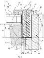
- Fig. 2 a schematic cross-sectional view of a hinge device 2 is illustrated.
- the cross section is taken in a plane perpendicular to the pane 5, as seen in a direction along the pane 5, from the bottom of the roof window 1 and viewed upwards when the roof window 1 is in a closed state.
- a break-out view along the circle A is shown in Fig. 3 .
- the hinge device 2 comprises a pair of hinges of which the right-hand hinge 6 is shown in Fig. 2 and which are arranged on either side of the pane 5 between the frame 4 and the sash 3.
- the left-hand hinge of the hinge device 2 is typically identical but mirror-inverted or of similar configuration, and only the right-hand hinge 6 will be described.
- the pane 5 has an exterior surface 55 and an interior surface 53, and the sash 3 and frame 4 each has an interior side adapted to face the interior 8 of the building in the mounted condition and an exterior side adapted to face the exterior 7 of the building in the mounted condition of the roof window 1.
- the frame 4 comprises a frame recess 44 facing the sash 3 and in which at least part of each hinge of the hinge device 2 is arranged in that a major part of the hinge 6 is accommodated within the frame recess 44.
- the frame recess 44 has a frame recess depth df and a frame recess width wf.
- the frame recess depth df of the frame recess 44 is defined from an exterior surface 45 and toward the interior, ending in a first recess surface 44a.
- the frame recess width wf is defined from inward frame surface 43 and outward, ending in a second recess surface 44b.
- the frame recess 44 does not break through the frame 4, i.e. for instance all the way to the outer side. This is due to the need of insulation of the window 1. However, it may be possible that the frame hinge recess 44 breaks through, if sufficient additional insulation is provided so that it fulfils the current needs.
- the hinge 6 comprises a sash hinge part 61 and a frame hinge part 62, here of substantially equal width.
- the sash hinge part 61 is connected to the sash 3 and the frame hinge part 62 is connected to the frame 4.
- the sash hinge part 61 and the frame hinge part 62 are coupled to each other such that relative movement is allowed. The relative movement is such that the sash 3 pivots in the frame 4 so that the window can be opened and closed.
- the hinge 6 is defined by a hinge height hh extending between an exterior edge 64 and an interior edge 65, and a hinge width wh extending between an outward side edge 66 and an inward side edge 67.
- the hinge 6 is arranged within the frame recess 44 such that a major part, constituted by at least 60% of the hinge width wh, is located within the frame recess width wf. In the embodiment shown in Figs 2 and 3 , approximately 70% of the width of the hinge is accommodated in the frame recess 44. In principle, larger portions of the hinge 6 may be accommodated, for instance more than 80% or, as will be described below, the entire hinge 6.
- the sash 3 comprises a sash hinge recess 34 in the embodiment shown in Figs 2 and 4 .
- the sash hinge recess 34 may be arranged to house a remaining part of the hinge 6 as shown in Fig. 2 .
- the sash hinge recess 34 has a depth ds and a width ws.
- the hinge 6 may thus be arranged in the frame 4 and in the sash 3, such that most of the hinge is arranged within the frame 4. In this manner, the hinge 6 is protected within the frame 4.
- a narrow sash 3 may be provided, and thus a narrower structure of the hinge device 2 altogether may be obtained.
- the inward frame surface 43 may be brought as close to an outward edge 52 of the pane 5 as possible.
- the sash 3 may become narrower as the sash hinge recess 34 becomes narrower and subsequently the frame hinge recess width wf becomes wider.
- the hinge 6 may be brought further into the frame 4.
- the most part of the insulation of the hinge 6 may be provided by the frame 4.
- a narrow sash may be provided by allowing the outward edge 52 of the pane 5 to be brought as close as possible to the inward frame surface 43.
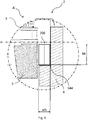
- Fig. 4 shows a second embodiment. Only differences relative to the first embodiment will be described in detail. Reference numerals having the same or analogous function are denoted by the same reference numeral as in the first embodiment, to which 100 has been added.
- the frame recess 144 is located towards an interior surface 46 of the frame and thus extends between interior surface 46 to first recess surface 144a. In that way, a low profile may be provided since the hinge 106 is completely located away from the exterior 8.
- the hinge 106 is completely located within the frame hinge recess 144. In other words, the sash 3 does not enclose any of the hinge 106.
- the hinge location relative to the frame and the sash respectively can be viewed.
- the sash 3 can however be provided with a sash hinge recess 34 to partially house the hinge 6.
- the hinge 6 is located so that an interior edge 67 is located at a distance d3 from the exterior surface 45 of the frame.
- a sash side edge 68 of the hinge is the edge that is directed towards the sash 3 and a frame side edge 69 is the side that is directed towards the frame.
- the location of the hinge can be described with the parameters w1, w2, d1, d2, d and d4.
- d1 is the distance between the exterior surface 55 of the pane 5 and the interior edge 67 of the hinge.
- first width w1 is the location of the frame side edge 69 of the hinge 6 relative to the inward frame surface 43.
- Second width w2 is the location of the frame side edge 69 relative to the outward edge 52 of the pane. In Fig. 4 , there is no sash recess, and the hinge is completely enclosed in the frame 3.
- Fig. 5 schematically illustrates a third embodiment in which the hinge 6 corresponds to that of the first embodiment, but the frame recess 244 is made deeper and wider, such that substantially the entire hinge 206 is arranged in the frame recess 244.
- the frame recess 44; 144; 244; 344 is provided with such a depth df that at least 60% of the depth of the hinge 6; 106; 306 is arranged therein such that the hinge extends at least partially to the interior of the exterior surface 55 of the pane 5, as seen from a plane perpendicular to the pane 5.
- the relation between the pane and the frame may also be varied, such that in certain embodiments, the pane 5 is arranged relative to the frame 4 such that an outward edge 52 of the pane 5 facing the frame 4 is arranged at a distance from an inward frame surface 43 of the frame 4 facing the sash (3) of not more than 50% of the width of the hinge, preferably less than 25%, and most preferably between 0-15% .
- the exterior surface 55 of the pane 5 may be substantially flush with the exterior surface 45 of the frame 4.
- hinge axis By the term “low” etc. regarding the hinge axis, it is noted that a suitable definition is found in that the pair of hinges of the hinge device is located such that the hinge axis ⁇ is positioned to the interior of the interior surface 53 of the pane 5.
- the hinge itself may in principle be of any suitable kind, however since the hinge axis is located relatively low in the roof window, the hinge axis is located near the centre of gravity of the window. Hence, the need for compensating for the offsetting of the centre of gravity during opening and closing of the window is reduced or even substantially eliminated.
- a pivot hinge having a hinge pin defining an axis of rotation substantially coinciding with the hinge axis ⁇ of the roof window pin is shown in the embodiment of Fig. 2g of WO 2010/088904 A1 .
- such a hinge could be the hinge 6 of the first and third embodiments.
- a traditional pivot hinge including a guidance and a slide rail defining an axis of rotation offset from the hinge centre could be used for the second embodiment shown in Fig. 4 .
- a traditional pivot hinge is shown in EP 1038083 B1 , and is commercially available standard on many roof windows.
- the pivot hinge 306 has a set of predefined dimensions, of which at least two dimensions are smaller than the corresponding dimensions of a pivot hinge which come as standard on many roof windows. This applies both to the length, width and/or thickness dimensions and any combination thereof, including the components of the pivot hinge.
Landscapes
- Engineering & Computer Science (AREA)
- Architecture (AREA)
- Civil Engineering (AREA)
- Structural Engineering (AREA)
- Wing Frames And Configurations (AREA)
Claims (14)
- Dachfenster (1), aufweisend einen Fensterflügel (3) und einen Rahmen (4), wobei der Fensterflügel und der Rahmen jeweils zwei seitliche Elemente, ein oberes Element und ein unteres Element aufweisen und jeweils eine Rahmenöffnung und eine Fensterflügelöffnung begrenzen, wobei der Fensterflügel (3) eine Fensterscheibe (5) trägt und mit dem Rahmen (4) über eine Scharniervorrichtung (2) verbunden ist, welche ein Paar Scharniere (6) umfasst, welches eine zwischen einer Mittelachse und dem Oberteil des Dachfensters festgelegte Scharnierachse (α) derartig definiert, dass die Scharnierachse (α) in der Nähe des Schwerpunktes des Dachfensters (1) positioniert ist oder sogar mit diesem zusammenfällt, wobei jedes Scharnier (6; 306) des Paares Scharniere einen Fensterflügel-Scharnierteil (61) und einen Rahmen-Scharnierteil (62) von im Wesentlichen gleicher Breite aufweist, wobei der Fensterflügel-Scharnierteil (61) und der Rahmen-Scharnierteil (62) derartig miteinander gekoppelt sind, dass eine relative Bewegung zugelassen wird, wobei der Rahmen (4) dafür angepasst ist, um mit einer tragenden Struktur eines Daches eines Gebäudes verbunden zu werden, bei welchem die Fensterscheibe (5) eine äußere Fläche (55) und eine innere Fläche (53) aufweist und der Fensterflügel (3) und Rahmen (4) jeweils eine innere Seite, welche angepasst ist, im montierten Zustand in Richtung nach dem Innenbereich (8) des Gebäudes zu zeigen, und eine äußere Seite aufweisen, welche angepasst ist, im montierten Zustand in Richtung nach dem Außenbereich (7) des Gebäudes zu zeigen, wobei das Paar Scharniere (6) an beiden Seiten der Fensterscheibe (5) zwischen dem Rahmen (4) und dem Fensterflügel (3) angeordnet sind, und bei welchem der Rahmen (4) eine in Richtung nach dem Fensterflügel (3) zeigende Rahmenaussparung (44) aufweist und in welcher zumindest ein Teil von jedem Scharnier (6) angeordnet ist, wobei die Rahmenaussparung (44) eine Rahmenaussparungstiefe (df) und eine Rahmenaussparungsbreite (wf) aufweist,
dadurch gekennzeichnet, dass
die Rahmenaussparung (44; 144; 244; 344) mit einer derartigen Rahmenaussparungsbreite (wf) vorgesehen ist, dass mindestens 60% der Breite von jedem Scharnier (6) in der Rahmenaussparung angeordnet ist. - Dachfenster nach Anspruch 1, wobei mindestens 80% der Breite von jedem Scharnier (6; 306) in der Rahmenaussparung (144; 244; 344) angeordnet ist.
- Dachfenster nach Anspruch 1 oder 2, wobei der verbleibende Teil der Breite von jedem Scharnier (6) innerhalb einer Fensterflügelaussparung (34) des Fensterflügels (3) und/oder in einem zwischen dem Rahmen (4) und dem Fensterflügel (3) gebildeten Spalt (9) angeordnet ist.
- Dachfenster nach Anspruch 1 oder 2, wobei im Wesentlichen das gesamte Scharnier (6) in der Rahmenaussparung (144; 244) angeordnet ist.
- Dachfenster nach einem der vorhergehenden Ansprüche, wobei die Rahmenaussparung (44; 144; 244; 344) mit einer derartigen Tiefe (df) vorgesehen ist, dass mindestens 60% der Tiefe des Scharniers (6) darin derartig angeordnet ist, dass das Scharnier (6) sich zumindest teilweise in den Innenbereich der äußeren Fläche (55) der Fensterscheibe (5) erstreckt, wenn von einer Ebene senkrecht zu der Fensterscheibe (5) geblickt wird.
- Dachfenster (1) nach Anspruch 5, wobei die Rahmenaussparung (244; 344) mit einer derartigen Rahmenaussparungstiefe (df) vorgesehen ist, dass im Wesentlichen das gesamte Scharnier (6) in der Rahmenaussparung (244; 344) angeordnet ist.
- Dachfenster (1) nach einem der vorhergehenden Ansprüche, wobei die Fensterscheibe (5) derartig relativ zu dem Rahmen (4) angeordnet ist, dass eine äußere Kante (52) der Fensterscheibe (5), welche in Richtung nach dem Rahmen (4) zeigt, in einem Abstand von einer inneren, in Richtung nach dem Fensterflügel (3) zeigenden Rahmenfläche (43) des Rahmens (4) von nicht mehr als 50% der Breite des Scharniers, vorzugsweise weniger als 25% und besonders bevorzugt zwischen 0-15% angeordnet ist.
- Dachfenster (1) nach einem der vorhergehenden Ansprüche, wobei die äußere Fläche (55) der Fensterscheibe (5) im Wesentlichen bündig mit einer äußeren Fläche (45) des Rahmens (4) ist.
- Dachfenster nach einem der vorhergehenden Ansprüche, wobei die Rahmenaussparung (44; 244; 344) in einer äußeren Fläche (45) des Rahmens (4) angeordnet ist.
- Dachfenster nach einem der Ansprüche 1 bis 8, wobei die Rahmenaussparung (144) in einer inneren Fläche des Rahmens angeordnet ist.
- Dachfenster nach einem der vorhergehenden Ansprüche, wobei das Paar Scharniere (6) derartig festgelegt ist, dass die Scharnierachse (α) in dem Innenbereich der inneren Fläche (53) der Fensterscheibe (5) positioniert ist.
- Dachfenster nach einem der vorhergehenden Ansprüche, wobei das Scharnier (6) ein Drehscharnier ist, welches einen Scharnierzapfen umfasst, welcher eine im Wesentlichen mit der Scharnierachse (α) des Dachfensters zusammenfallende Drehachse definiert.
- Dachfenster nach einem der Ansprüche 1 bis 11, wobei das Scharnier (306) ein Drehscharnier ist, welches eine Führung und eine Gleitschiene umfasst, welche eine von der Scharniermitte versetzte Drehachse definiert.
- Dachfenster nach Anspruch 13, wobei das Drehscharnier (306) einen Satz von vordefinierten Abmessungen aufweist, von welchen mindestens zwei Abmessungen kleiner als die entsprechenden Abmessungen eines herkömmlichen Drehscharniers sind.
Applications Claiming Priority (1)
| Application Number | Priority Date | Filing Date | Title |
|---|---|---|---|
| DKPA201670675A DK179926B1 (en) | 2016-09-02 | 2016-09-02 | A ROOF WINDOW WITH IMPROVED INSULATION PROPERTIES AND INCLUDING A SET OF HINGES |
Publications (2)
| Publication Number | Publication Date |
|---|---|
| EP3290614A1 EP3290614A1 (de) | 2018-03-07 |
| EP3290614B1 true EP3290614B1 (de) | 2020-08-19 |
Family
ID=59761857
Family Applications (1)
| Application Number | Title | Priority Date | Filing Date |
|---|---|---|---|
| EP17189065.0A Active EP3290614B1 (de) | 2016-09-02 | 2017-09-01 | Dachfenster mit verbesserten isolierungseigenschaften und mit einem satz an scharnieren |
Country Status (2)
| Country | Link |
|---|---|
| EP (1) | EP3290614B1 (de) |
| DK (1) | DK179926B1 (de) |
Cited By (1)
| Publication number | Priority date | Publication date | Assignee | Title |
|---|---|---|---|---|
| EP3783161B1 (de) * | 2020-02-03 | 2022-01-26 | VKR Holding | Dachfenster |
Family Cites Families (11)
| Publication number | Priority date | Publication date | Assignee | Title |
|---|---|---|---|---|
| DE940755C (de) * | 1953-04-30 | 1956-03-22 | Albers & V Drathen | Fluegel fuer Fenster, insbesondere Dachfenster |
| DE1917594B2 (de) * | 1969-04-05 | 1977-09-22 | Handel, Erwin, 7315 Weilheim | Beschlag an kippfenstern |
| DE2102937C3 (de) * | 1971-01-22 | 1975-12-11 | Hoesch Werke Ag, 4600 Dortmund | Lager für Fensterflügel von Wohnraum-Dachfenstern |
| DE2438437A1 (de) * | 1974-05-08 | 1976-02-19 | Winkhaus Fa August | Dachflaechenfenster |
| PL1674634T3 (pl) * | 2004-12-24 | 2019-10-31 | Vkr Holding As | Ościeżnica okna dachowego przystosowana do produkcji standaryzowanej |
| PL220967B1 (pl) * | 2007-11-02 | 2016-02-29 | Fakro Pp Spółka Z Ograniczoną Odpowiedzialnością | Okno uchylno-obrotowe, zwłaszcza dachowe |
| PL217849B1 (pl) * | 2008-07-11 | 2014-08-29 | Fakro Pp Spółka Z Ograniczoną Odpowiedzialnością | Rama drewniana okna, zwłaszcza dachowego |
| EP3342972B1 (de) * | 2009-02-03 | 2021-03-24 | VKR Holding A/S | Fenster mit einem flügel und einer verbesserten verbindung mit dem scharnier |
| CN204252419U (zh) * | 2011-10-04 | 2015-04-08 | Vkr控股公司 | 具有改进的冲击水珠覆盖件的屋顶天窗 |
| DE202012006688U1 (de) * | 2012-07-10 | 2013-10-14 | Vkr Holding A/S | Dachfenster mit Abdeckmitteln für einen Rahmen |
| PL228463B1 (pl) * | 2014-03-17 | 2018-03-30 | Fakro Pp Spolka Z Ograniczona Odpowiedzialnoscia | Okno dachowe z zawiasem o podwyzszonej odpornosci na włamanie |
-
2016
- 2016-09-02 DK DKPA201670675A patent/DK179926B1/en not_active IP Right Cessation
-
2017
- 2017-09-01 EP EP17189065.0A patent/EP3290614B1/de active Active
Non-Patent Citations (1)
| Title |
|---|
| None * |
Cited By (1)
| Publication number | Priority date | Publication date | Assignee | Title |
|---|---|---|---|---|
| EP3783161B1 (de) * | 2020-02-03 | 2022-01-26 | VKR Holding | Dachfenster |
Also Published As
| Publication number | Publication date |
|---|---|
| DK179926B1 (en) | 2019-10-09 |
| DK201670675A1 (en) | 2018-03-12 |
| EP3290614A1 (de) | 2018-03-07 |
Similar Documents
| Publication | Publication Date | Title |
|---|---|---|
| CN102359329B (zh) | 门 | |
| JP2016142027A (ja) | 樹脂サッシ | |
| EP3290614B1 (de) | Dachfenster mit verbesserten isolierungseigenschaften und mit einem satz an scharnieren | |
| EP1989385B1 (de) | Wärmebeständiges fensterrahmenglied und fensteranordnung | |
| JP4027920B2 (ja) | 樹脂サッシ | |
| JP6031408B2 (ja) | 上げ下げ窓 | |
| KR101450303B1 (ko) | 방범 및 난간 기능이 일체화된 슬림형 쓰리트랙 단열 창호 | |
| EP3564461B1 (de) | Dachfenster mit verbesserter abdeckungsanordnung | |
| EP2307216B1 (de) | Fahrzeugtürsysteme | |
| JP2009221809A (ja) | 外部開口用サッシの水密構造 | |
| JP5658080B2 (ja) | サッシ | |
| JP6749833B2 (ja) | 建具 | |
| JP2832802B2 (ja) | 窓 枠 | |
| EP1687502A1 (de) | Fenster- oder türkonstruktion mit einem verschlussstück | |
| WO2004027194A1 (en) | Window or door structure with a cavity between the sash and frame | |
| JP7316881B2 (ja) | 障子及び建具 | |
| EP3299536B1 (de) | Dachfenster mit einem satz von scharnieren mit verbessertem bewegungsmuster | |
| EP2674561B1 (de) | Wärmebeständiges Fensterrahmenglied und Fensteranordnung | |
| JP6310032B2 (ja) | 上げ下げ窓 | |
| US8850759B2 (en) | Window | |
| KR101746904B1 (ko) | 회전 도어 조립체 | |
| JP6710632B2 (ja) | 建具 | |
| JP6981845B2 (ja) | 戸先框用遮光部材及び窓装置 | |
| JP6652435B2 (ja) | 建具 | |
| JP6726507B2 (ja) | 建具 |
Legal Events
| Date | Code | Title | Description |
|---|---|---|---|
| PUAI | Public reference made under article 153(3) epc to a published international application that has entered the european phase |
Free format text: ORIGINAL CODE: 0009012 |
|
| STAA | Information on the status of an ep patent application or granted ep patent |
Free format text: STATUS: THE APPLICATION HAS BEEN PUBLISHED |
|
| AK | Designated contracting states |
Kind code of ref document: A1 Designated state(s): AL AT BE BG CH CY CZ DE DK EE ES FI FR GB GR HR HU IE IS IT LI LT LU LV MC MK MT NL NO PL PT RO RS SE SI SK SM TR |
|
| AX | Request for extension of the european patent |
Extension state: BA ME |
|
| STAA | Information on the status of an ep patent application or granted ep patent |
Free format text: STATUS: REQUEST FOR EXAMINATION WAS MADE |
|
| 17P | Request for examination filed |
Effective date: 20180905 |
|
| RBV | Designated contracting states (corrected) |
Designated state(s): AL AT BE BG CH CY CZ DE DK EE ES FI FR GB GR HR HU IE IS IT LI LT LU LV MC MK MT NL NO PL PT RO RS SE SI SK SM TR |
|
| STAA | Information on the status of an ep patent application or granted ep patent |
Free format text: STATUS: EXAMINATION IS IN PROGRESS |
|
| 17Q | First examination report despatched |
Effective date: 20200128 |
|
| GRAP | Despatch of communication of intention to grant a patent |
Free format text: ORIGINAL CODE: EPIDOSNIGR1 |
|
| STAA | Information on the status of an ep patent application or granted ep patent |
Free format text: STATUS: GRANT OF PATENT IS INTENDED |
|
| INTG | Intention to grant announced |
Effective date: 20200526 |
|
| GRAS | Grant fee paid |
Free format text: ORIGINAL CODE: EPIDOSNIGR3 |
|
| GRAA | (expected) grant |
Free format text: ORIGINAL CODE: 0009210 |
|
| STAA | Information on the status of an ep patent application or granted ep patent |
Free format text: STATUS: THE PATENT HAS BEEN GRANTED |
|
| AK | Designated contracting states |
Kind code of ref document: B1 Designated state(s): AL AT BE BG CH CY CZ DE DK EE ES FI FR GB GR HR HU IE IS IT LI LT LU LV MC MK MT NL NO PL PT RO RS SE SI SK SM TR |
|
| REG | Reference to a national code |
Ref country code: CH Ref legal event code: EP |
|
| REG | Reference to a national code |
Ref country code: DE Ref legal event code: R096 Ref document number: 602017021818 Country of ref document: DE |
|
| REG | Reference to a national code |
Ref country code: AT Ref legal event code: REF Ref document number: 1304092 Country of ref document: AT Kind code of ref document: T Effective date: 20200915 |
|
| REG | Reference to a national code |
Ref country code: IE Ref legal event code: FG4D |
|
| REG | Reference to a national code |
Ref country code: LT Ref legal event code: MG4D |
|
| REG | Reference to a national code |
Ref country code: NL Ref legal event code: MP Effective date: 20200819 |
|
| PG25 | Lapsed in a contracting state [announced via postgrant information from national office to epo] |
Ref country code: NO Free format text: LAPSE BECAUSE OF FAILURE TO SUBMIT A TRANSLATION OF THE DESCRIPTION OR TO PAY THE FEE WITHIN THE PRESCRIBED TIME-LIMIT Effective date: 20201119 Ref country code: BG Free format text: LAPSE BECAUSE OF FAILURE TO SUBMIT A TRANSLATION OF THE DESCRIPTION OR TO PAY THE FEE WITHIN THE PRESCRIBED TIME-LIMIT Effective date: 20201119 Ref country code: LT Free format text: LAPSE BECAUSE OF FAILURE TO SUBMIT A TRANSLATION OF THE DESCRIPTION OR TO PAY THE FEE WITHIN THE PRESCRIBED TIME-LIMIT Effective date: 20200819 Ref country code: PT Free format text: LAPSE BECAUSE OF FAILURE TO SUBMIT A TRANSLATION OF THE DESCRIPTION OR TO PAY THE FEE WITHIN THE PRESCRIBED TIME-LIMIT Effective date: 20201221 Ref country code: GR Free format text: LAPSE BECAUSE OF FAILURE TO SUBMIT A TRANSLATION OF THE DESCRIPTION OR TO PAY THE FEE WITHIN THE PRESCRIBED TIME-LIMIT Effective date: 20201120 Ref country code: HR Free format text: LAPSE BECAUSE OF FAILURE TO SUBMIT A TRANSLATION OF THE DESCRIPTION OR TO PAY THE FEE WITHIN THE PRESCRIBED TIME-LIMIT Effective date: 20200819 Ref country code: SE Free format text: LAPSE BECAUSE OF FAILURE TO SUBMIT A TRANSLATION OF THE DESCRIPTION OR TO PAY THE FEE WITHIN THE PRESCRIBED TIME-LIMIT Effective date: 20200819 Ref country code: FI Free format text: LAPSE BECAUSE OF FAILURE TO SUBMIT A TRANSLATION OF THE DESCRIPTION OR TO PAY THE FEE WITHIN THE PRESCRIBED TIME-LIMIT Effective date: 20200819 |
|
| REG | Reference to a national code |
Ref country code: AT Ref legal event code: MK05 Ref document number: 1304092 Country of ref document: AT Kind code of ref document: T Effective date: 20200819 |
|
| PG25 | Lapsed in a contracting state [announced via postgrant information from national office to epo] |
Ref country code: RS Free format text: LAPSE BECAUSE OF FAILURE TO SUBMIT A TRANSLATION OF THE DESCRIPTION OR TO PAY THE FEE WITHIN THE PRESCRIBED TIME-LIMIT Effective date: 20200819 Ref country code: LV Free format text: LAPSE BECAUSE OF FAILURE TO SUBMIT A TRANSLATION OF THE DESCRIPTION OR TO PAY THE FEE WITHIN THE PRESCRIBED TIME-LIMIT Effective date: 20200819 Ref country code: NL Free format text: LAPSE BECAUSE OF FAILURE TO SUBMIT A TRANSLATION OF THE DESCRIPTION OR TO PAY THE FEE WITHIN THE PRESCRIBED TIME-LIMIT Effective date: 20200819 Ref country code: IS Free format text: LAPSE BECAUSE OF FAILURE TO SUBMIT A TRANSLATION OF THE DESCRIPTION OR TO PAY THE FEE WITHIN THE PRESCRIBED TIME-LIMIT Effective date: 20201219 |
|
| PG25 | Lapsed in a contracting state [announced via postgrant information from national office to epo] |
Ref country code: CZ Free format text: LAPSE BECAUSE OF FAILURE TO SUBMIT A TRANSLATION OF THE DESCRIPTION OR TO PAY THE FEE WITHIN THE PRESCRIBED TIME-LIMIT Effective date: 20200819 Ref country code: DK Free format text: LAPSE BECAUSE OF FAILURE TO SUBMIT A TRANSLATION OF THE DESCRIPTION OR TO PAY THE FEE WITHIN THE PRESCRIBED TIME-LIMIT Effective date: 20200819 Ref country code: RO Free format text: LAPSE BECAUSE OF FAILURE TO SUBMIT A TRANSLATION OF THE DESCRIPTION OR TO PAY THE FEE WITHIN THE PRESCRIBED TIME-LIMIT Effective date: 20200819 Ref country code: SM Free format text: LAPSE BECAUSE OF FAILURE TO SUBMIT A TRANSLATION OF THE DESCRIPTION OR TO PAY THE FEE WITHIN THE PRESCRIBED TIME-LIMIT Effective date: 20200819 Ref country code: EE Free format text: LAPSE BECAUSE OF FAILURE TO SUBMIT A TRANSLATION OF THE DESCRIPTION OR TO PAY THE FEE WITHIN THE PRESCRIBED TIME-LIMIT Effective date: 20200819 |
|
| REG | Reference to a national code |
Ref country code: CH Ref legal event code: PL |
|
| REG | Reference to a national code |
Ref country code: DE Ref legal event code: R097 Ref document number: 602017021818 Country of ref document: DE |
|
| PG25 | Lapsed in a contracting state [announced via postgrant information from national office to epo] |
Ref country code: AL Free format text: LAPSE BECAUSE OF FAILURE TO SUBMIT A TRANSLATION OF THE DESCRIPTION OR TO PAY THE FEE WITHIN THE PRESCRIBED TIME-LIMIT Effective date: 20200819 Ref country code: AT Free format text: LAPSE BECAUSE OF FAILURE TO SUBMIT A TRANSLATION OF THE DESCRIPTION OR TO PAY THE FEE WITHIN THE PRESCRIBED TIME-LIMIT Effective date: 20200819 Ref country code: ES Free format text: LAPSE BECAUSE OF FAILURE TO SUBMIT A TRANSLATION OF THE DESCRIPTION OR TO PAY THE FEE WITHIN THE PRESCRIBED TIME-LIMIT Effective date: 20200819 Ref country code: MC Free format text: LAPSE BECAUSE OF FAILURE TO SUBMIT A TRANSLATION OF THE DESCRIPTION OR TO PAY THE FEE WITHIN THE PRESCRIBED TIME-LIMIT Effective date: 20200819 |
|
| REG | Reference to a national code |
Ref country code: BE Ref legal event code: MM Effective date: 20200930 |
|
| PLBE | No opposition filed within time limit |
Free format text: ORIGINAL CODE: 0009261 |
|
| STAA | Information on the status of an ep patent application or granted ep patent |
Free format text: STATUS: NO OPPOSITION FILED WITHIN TIME LIMIT |
|
| PG25 | Lapsed in a contracting state [announced via postgrant information from national office to epo] |
Ref country code: SK Free format text: LAPSE BECAUSE OF FAILURE TO SUBMIT A TRANSLATION OF THE DESCRIPTION OR TO PAY THE FEE WITHIN THE PRESCRIBED TIME-LIMIT Effective date: 20200819 Ref country code: LU Free format text: LAPSE BECAUSE OF NON-PAYMENT OF DUE FEES Effective date: 20200901 |
|
| 26N | No opposition filed |
Effective date: 20210520 |
|
| PG25 | Lapsed in a contracting state [announced via postgrant information from national office to epo] |
Ref country code: IT Free format text: LAPSE BECAUSE OF FAILURE TO SUBMIT A TRANSLATION OF THE DESCRIPTION OR TO PAY THE FEE WITHIN THE PRESCRIBED TIME-LIMIT Effective date: 20200819 |
|
| PG25 | Lapsed in a contracting state [announced via postgrant information from national office to epo] |
Ref country code: IE Free format text: LAPSE BECAUSE OF NON-PAYMENT OF DUE FEES Effective date: 20200901 Ref country code: LI Free format text: LAPSE BECAUSE OF NON-PAYMENT OF DUE FEES Effective date: 20200930 Ref country code: SI Free format text: LAPSE BECAUSE OF FAILURE TO SUBMIT A TRANSLATION OF THE DESCRIPTION OR TO PAY THE FEE WITHIN THE PRESCRIBED TIME-LIMIT Effective date: 20200819 Ref country code: BE Free format text: LAPSE BECAUSE OF NON-PAYMENT OF DUE FEES Effective date: 20200930 Ref country code: CH Free format text: LAPSE BECAUSE OF NON-PAYMENT OF DUE FEES Effective date: 20200930 |
|
| PG25 | Lapsed in a contracting state [announced via postgrant information from national office to epo] |
Ref country code: TR Free format text: LAPSE BECAUSE OF FAILURE TO SUBMIT A TRANSLATION OF THE DESCRIPTION OR TO PAY THE FEE WITHIN THE PRESCRIBED TIME-LIMIT Effective date: 20200819 Ref country code: MT Free format text: LAPSE BECAUSE OF FAILURE TO SUBMIT A TRANSLATION OF THE DESCRIPTION OR TO PAY THE FEE WITHIN THE PRESCRIBED TIME-LIMIT Effective date: 20200819 Ref country code: CY Free format text: LAPSE BECAUSE OF FAILURE TO SUBMIT A TRANSLATION OF THE DESCRIPTION OR TO PAY THE FEE WITHIN THE PRESCRIBED TIME-LIMIT Effective date: 20200819 |
|
| PG25 | Lapsed in a contracting state [announced via postgrant information from national office to epo] |
Ref country code: MK Free format text: LAPSE BECAUSE OF FAILURE TO SUBMIT A TRANSLATION OF THE DESCRIPTION OR TO PAY THE FEE WITHIN THE PRESCRIBED TIME-LIMIT Effective date: 20200819 |
|
| PGFP | Annual fee paid to national office [announced via postgrant information from national office to epo] |
Ref country code: GB Payment date: 20230803 Year of fee payment: 7 |
|
| PGFP | Annual fee paid to national office [announced via postgrant information from national office to epo] |
Ref country code: PL Payment date: 20230816 Year of fee payment: 7 Ref country code: FR Payment date: 20230821 Year of fee payment: 7 Ref country code: DE Payment date: 20230802 Year of fee payment: 7 |