EP3299254B1 - Lenkvorrichtung eines fahrzeugs - Google Patents
Lenkvorrichtung eines fahrzeugs Download PDFInfo
- Publication number
- EP3299254B1 EP3299254B1 EP17179270.8A EP17179270A EP3299254B1 EP 3299254 B1 EP3299254 B1 EP 3299254B1 EP 17179270 A EP17179270 A EP 17179270A EP 3299254 B1 EP3299254 B1 EP 3299254B1
- Authority
- EP
- European Patent Office
- Prior art keywords
- holding member
- inner tube
- tube
- axial direction
- outer tube
- Prior art date
- Legal status (The legal status is an assumption and is not a legal conclusion. Google has not performed a legal analysis and makes no representation as to the accuracy of the status listed.)
- Not-in-force
Links
Images


Classifications
-
- B—PERFORMING OPERATIONS; TRANSPORTING
- B62—LAND VEHICLES FOR TRAVELLING OTHERWISE THAN ON RAILS
- B62D—MOTOR VEHICLES; TRAILERS
- B62D1/00—Steering controls, i.e. means for initiating a change of direction of the vehicle
- B62D1/02—Steering controls, i.e. means for initiating a change of direction of the vehicle vehicle-mounted
- B62D1/16—Steering columns
- B62D1/18—Steering columns yieldable or adjustable, e.g. tiltable
- B62D1/19—Steering columns yieldable or adjustable, e.g. tiltable incorporating energy-absorbing arrangements, e.g. by being yieldable or collapsible
- B62D1/192—Yieldable or collapsible columns
-
- B—PERFORMING OPERATIONS; TRANSPORTING
- B62—LAND VEHICLES FOR TRAVELLING OTHERWISE THAN ON RAILS
- B62D—MOTOR VEHICLES; TRAILERS
- B62D1/00—Steering controls, i.e. means for initiating a change of direction of the vehicle
- B62D1/02—Steering controls, i.e. means for initiating a change of direction of the vehicle vehicle-mounted
- B62D1/16—Steering columns
- B62D1/18—Steering columns yieldable or adjustable, e.g. tiltable
- B62D1/181—Steering columns yieldable or adjustable, e.g. tiltable with power actuated adjustment, e.g. with position memory
-
- B—PERFORMING OPERATIONS; TRANSPORTING
- B62—LAND VEHICLES FOR TRAVELLING OTHERWISE THAN ON RAILS
- B62D—MOTOR VEHICLES; TRAILERS
- B62D1/00—Steering controls, i.e. means for initiating a change of direction of the vehicle
- B62D1/02—Steering controls, i.e. means for initiating a change of direction of the vehicle vehicle-mounted
- B62D1/16—Steering columns
- B62D1/18—Steering columns yieldable or adjustable, e.g. tiltable
- B62D1/185—Steering columns yieldable or adjustable, e.g. tiltable adjustable by axial displacement, e.g. telescopically
-
- B—PERFORMING OPERATIONS; TRANSPORTING
- B62—LAND VEHICLES FOR TRAVELLING OTHERWISE THAN ON RAILS
- B62D—MOTOR VEHICLES; TRAILERS
- B62D1/00—Steering controls, i.e. means for initiating a change of direction of the vehicle
- B62D1/02—Steering controls, i.e. means for initiating a change of direction of the vehicle vehicle-mounted
- B62D1/16—Steering columns
- B62D1/18—Steering columns yieldable or adjustable, e.g. tiltable
- B62D1/187—Steering columns yieldable or adjustable, e.g. tiltable with tilt adjustment; with tilt and axial adjustment
-
- B—PERFORMING OPERATIONS; TRANSPORTING
- B62—LAND VEHICLES FOR TRAVELLING OTHERWISE THAN ON RAILS
- B62D—MOTOR VEHICLES; TRAILERS
- B62D5/00—Power-assisted or power-driven steering
- B62D5/04—Power-assisted or power-driven steering electrical, e.g. using an electric servo-motor connected to, or forming part of, the steering gear
- B62D5/0403—Power-assisted or power-driven steering electrical, e.g. using an electric servo-motor connected to, or forming part of, the steering gear characterised by constructional features, e.g. common housing for motor and gear box
-
- B—PERFORMING OPERATIONS; TRANSPORTING
- B62—LAND VEHICLES FOR TRAVELLING OTHERWISE THAN ON RAILS
- B62D—MOTOR VEHICLES; TRAILERS
- B62D5/00—Power-assisted or power-driven steering
- B62D5/04—Power-assisted or power-driven steering electrical, e.g. using an electric servo-motor connected to, or forming part of, the steering gear
- B62D5/0409—Electric motor acting on the steering column
Definitions
- This disclosure relates to a steering device of a vehicle, and particularly to a steering device that is provided with a telescopic mechanism capable of adjusting an operation position of a steering wheel in a front-rear direction of a vehicle body.
- JP 2009-298298 A discloses a "steering column” (see paragraphs [0024] to [0029] and Figs. 1 and 2 of Reference 1), and discloses a "telescopic actuating mechanism" (see paragraphs [0030] to [0032] and Figs. 6 and 7 of Reference 1).
- JP 2015-083396 A discloses a "steering device that absorbs energy applied to a steering shaft of a vehicle," that is, a steering device of a vehicle which includes an inner tube that accommodates the steering shaft of the vehicle so as to prevent a relative movement of the steering shaft in the axial direction, and to support the steering shaft to be rotatable about an axis and an outer tube that accommodates the inner tube so as to hold the inner tube at a predetermined position in a normal state, and the steering device is configured to allow a relative movement of the inner tube with respect to the outer tube in the axial direction when a load equal to or larger than a predetermined value is applied to the steering shaft (see paragraphs [0001] and [0007] of Reference 2).
- first tube The "first tube,” “second tube” and “third tube” in the steering column described in Reference 1 respectively correspond to "column housing,” “outer tube” and “inner tube” described in Reference 2, and in each steering column, a column tube is constituted with an inner tube that accommodates a steering shaft so as to support the steering shaft to be rotatable about the axis and the outer tube that accommodates the inner tube so as to hold the inner tube at a predetermined position in a normal state.
- the inner tube is made of a high specific gravity material such as iron in order to ensure the required rigidity.
- the outer tube is also made of a high specific gravity material such as weldable iron. Consequently, both the inner tube and the outer tube constituting the column tube have to be made of a high specific gravity material, and thus not only it is very hard to reduce the weight but also it is difficult to save the space.
- An aspect of this disclosure is directed to a steering device of a vehicle including: a column housing supported on a vehicle body; a column tube supported to be movable in an axial direction with respect to the column housing and configured to accommodate a steering shaft; and a telescopic mechanism configured to drive the column tube with respect to the column housing in the axial direction.
- the column tube includes an outer tube configured to accommodate the steering shaft and support the steering shaft to be rotatable around an axis of the steering shaft, and an inner tube accommodated in the outer tube, and the column tube is configured to allow a relative movement of the outer tube with respect to the inner tube in the axial direction when a load equal to or larger than a predetermined value is applied to the steering shaft.
- the telescopic mechanism includes a holding member and a driving mechanism connected to the holding member and supported by the column housing to drive the holding member in the axial direction, and the telescopic mechanism is configured to drive the inner tube and the outer tube with respect to the column housing in the axial direction by the driving mechanism.
- the above described "front-rear direction of a vehicle body” does not necessarily mean parallel to a road surface, but includes a direction inclined with the road surface (hereinafter, the same).
- the steering device further includes a bearing member interposed between the outer tube and the steering shaft so as to allow the steering shaft to be rotatably supported with respect to the outer tube, and to prevent a relative movement of the steering shaft in the axial direction.
- the steering device further includes a spring member interposed between the inner tube and the outer tube so as to restrict a relative movement between the inner tube and the outer tube in the axial direction.
- a spring member an annular spring member including a C shape may be used.
- the outer tube has an opening that allows the holding member to move in the axial direction, and the holding member is inserted through the opening to be connected to the driving mechanism. It is preferable that the opening of the outer tube is an opening whose longitudinal direction aligns with an axial direction of the outer tube, and may be configured to prevent movement of the holding member at both ends of the opening in the axial direction.
- the holding member is inserted through one side of the inner tube and is supported by another side of the inner tube to be connected to the driving mechanism. It is preferable that the holding member is configured as a tubular body having a flange portion at one end thereof, and the inner tube includes a first opening which is formed on the one side of the inner tube and through which the holding member is inserted, and a second opening which is formed on the another side of the inner tube at a position opposite to the first opening and has an annular groove formed inside the inner tube, and the holding member is inserted through the second opening such that the flange portion is fitted into the annular groove.
- the driving mechanism includes an electric motor supported by the column housing, a screw shaft connected to an output shaft of the electric motor, and a nut member screwed to the screw shaft and held by the holding member, and according to the rotational driving of the screw shaft by the electric motor, the nut member moves in an axial direction of the screw shaft, and the holding member may move in the axial direction together with the nut member so that the column tube moves in a front-rear direction of a vehicle body.
- the steering device of a vehicle which includes: a column housing supported on a vehicle body; a column tube accommodating a steering shaft and supported with respect to the column housing to be movable in an axial direction; and a telescopic mechanism that drives the column tube with respect to the column housing in the axial direction
- the aspect of this disclosure is configured such that the column tube includes an outer tube configured to accommodate the steering shaft and support the steering shaft to be rotatable around the axis of the steering shaft, and an inner tube accommodated in the outer tube, and the column tube is configured to allow a relative movement of the outer tube with respect to the inner tube in the axial direction when a load equal to or larger than a predetermined value is applied to the steering shaft.
- the telescopic mechanism includes a holding member, and a driving mechanism connected to the holding member and supported by the column housing to drive the holding member in the axial direction, and the telescopic mechanism is configured to drive the inner tube and the outer tube with respect to the column housing in the axial direction by the driving mechanism.
- the inner tube In a normal state, the inner tube is configured to hold the outer tube at a predetermined position.
- the holding member is supported by the inner tube.
- the steering device includes a bearing member interposed between the outer tube and the steering shaft so as to allow the steering shaft to be rotatably supported with respect to the outer tube, and to prevent a relative movement of the steering shaft in the axial direction, the load of the steering shaft may be borne by the outer tube, and a large load may be avoided from being applied to the inner tube. Therefore, it is possible to reduce the thickness of the inner tube and change the material of the inner tube to a low specific gravity material, so that the inner tube may be made of a synthetic resin and it is possible to achieve further weight reduction and space saving.
- the steering device includes a spring member interposed between the inner tube and the outer tube so as to restrict a relative movement between the inner tube and the outer tube in the axial direction, the outer tube moves forward against the biasing force of the spring member when a large load is applied to the steering shaft, so that energy is properly absorbed.
- an annular spring member including a C shape may be used as the spring member, and the spring member is accommodated in the outer tube in the state where the spring member is mounted on the inner tube, the assembly process is facilitated.
- the outer tube has an opening that allows the holding member to move in the axial direction and the holding member is configured to be inserted through the opening to be connected to the driving mechanism, it is possible to easily and properly secure the relative movement between the inner tube and the outer tube in the axial direction.
- the opening of the outer tube is an opening whose longitudinal direction aligns with an axial direction of the outer tube, and is configured to prevent movement of the holding member at both ends of the opening in the axial direction, it is possible to properly set the movable distance of the holding member, and even when a tensile force directed to the rear side of the vehicle is applied to the steering shaft, the holding member is locked at the position where the holding member is abutted on the front end of the opening in the axial direction. Therefore, the opening is also capable of effectively functioning to lock the outer tube.
- the holding member When the holding member is configured such that the holding member is inserted through one side of the inner tube to be supported by the other side of the inner tube and to be connected to the driving mechanism, the holding member may be easily and properly supported by the inner tube.
- the holding member when the holding member is configured as a tubular body having a flange portion at one end thereof, and the inner tube includes a first opening formed on one side of the inner tube and a second opening formed on the other side of the inner tube at a position opposite to the first opening, through which the holding member is inserted, the second opening has an annular groove formed inside the inner tube, and the holding member inserted into the second opening so that the flange portion is fitted into the annular groove, the holding member may be easily and properly fixed to the inner tube, so that it is possible to reliably prevent the holding member from falling off from the inner tube.
- the driving mechanism includes an electric motor supported by the column housing, a screw shaft connected to an output shaft of the electric motor, and a nut member screwed to the screw shaft and held by the holding member, and according to the rotational driving of the screw shaft by the electric motor, the nut member moves in an axial direction of the screw shaft, and the holding member moves in the axial direction together with the nut member so that the column tube moves in a front-rear direction of a vehicle body, it is possible to configure a telescopic mechanism that is capable of securing a smooth movement in the axial direction without requiring a large space.
- Figs. 1 to 3 illustrate the overall configuration of a steering device according to the embodiment disclosed herein, in which a column tube 1 accommodating a steering shaft 2 is supported to be movable in an axial direction with respect to a column housing 3 supported on a vehicle body VB via a fixing bracket BR, and a telescopic mechanism 4 that drives the column tube 1 in the axial direction is mounted on the column housing 3.
- the steering shaft 2 of the embodiment includes a tubular upper shaft 2x, the rear end portion of which is connected to a steering wheel SW, and a lower shaft 2y having an outer cylindrical surface splined to an inner cylindrical surface of the upper shaft 2x.
- the upper shaft 2x and the lower shaft 2y are connected to be relatively movable in the axial direction and relatively non-rotatable, and the front end portion of the lower shaft 2y is connected to a steering mechanism (not illustrated).
- the steering mechanism is configured to be driven according to the operation of the steering wheel SW and to steer a steering wheel (not illustrated) via a wheel steering mechanism (not illustrated).
- the column tube 1 includes an outer tube 10 made of a metal (e.g., iron) and an inner tube 20 made of a metal (e.g., an aluminum alloy), and the inner tube 20 is configured to be accommodated in the outer tube 10 and held at a predetermined position in a normal state.
- the outer tube 10 is configured to prevent a relative movement of the steering shaft 2 in the axial direction and to support the steering shaft 2 to be rotatable around the axis of the steering shaft 2. That is, a bearing member 12x is interposed between the outer tube 10 and the steering shaft 2 such that the steering shaft 2 is rotatably supported with respect to the outer tube 10 by the bearing member 12x, and the relative movement of the steering shaft 2 in the axial direction is prevented by the bearing member 12x.
- metallic annular spring members 13, 13 are interposed between the outer tube 10 and the inner tube 20 such that the relative movement between the inner tube 20 and the outer tube 10 in the axial direction is restricted by the annular spring members 13, 13. Therefore, the outer tube 10 is held at a predetermined position with respect to the inner tube 20 in the normal state. Meanwhile, when a load equal to or larger than a predetermined value is applied to the steering shaft 2, the relative movement of the outer tube 10 with respect to the inner tube 20 in the axial direction is allowed, and the outer tube 10 is configured to move in the axial direction integrally with the steering shaft 2.
- the outer tube 10 and the inner tube 20 serve as energy absorbing means together with the annular spring members 13, 13 or the like interposed therebetween.
- the annular spring members 13, 13 are formed in a C shape by stainless steel similarly to the annular spring member disclosed in, for example, the above described Reference 2, and has a plurality of protruding portions (not illustrated) having a hat-shaped cross section and formed evenly over the entire circumference thereof.
- Each of the spring members 13, 13 is arranged such that the side constituting a top portion of the hat-shaped cross section of each protruding portion becomes an inner peripheral surface, and the side constituting a flange portion of the hat-shaped cross section becomes an outer peripheral surface.
- the outer tube 10 is supported by the column housing 3 via a pair of bushings 14, 14 serving as sliding bearings.
- the outer tube 10 is pressed against the inner surface of the column housing 3 and held by a pair of pressing mechanisms 15, 15.
- the bushings 14, 14 may be made of a resin, but may be preferably made of a metal.
- Each of the pressing mechanisms 15, 15 is the same as a mechanism using a disc spring conventionally called a friction mechanism, and may secure a sliding ability in the thrust direction without causing rattle in the steering wheel SW, but does not serve as energy absorbing means between the column housing 3 and the outer tube 10.
- the telescopic mechanism 4 of the embodiment includes a holding member 30 supported by the inner tube 20, and a driving mechanism 40 connected to the holding member 30 and supported by the column housing 3 to drive the holding member 30 in the axial direction.
- the telescopic mechanism 4 is configured to drive the column tube 1 (the inner tube 20 and the outer tube 10) with respect to the column housing 3 in the axial direction by the driving mechanism 40.
- the holding member 30 is inserted through an opening 20a formed on one side of the inner tube 20, and is supported by an opening 20b formed on the other side.
- the column tube 1, the steering shaft 2, and the steering wheel SW integrally move with respect to the column housing 3 in the axial direction, and the steering wheel SW may be adjusted to a desired position in the front-rear direction of the vehicle body.
- the opening 10a, into which the holding member 30 is inserted, and the opening 10b, which extends in the longitudinal direction (the axial direction of the outer tube 10), are formed in the outer tube 10 according to the embodiment.
- the holding member 30 is inserted through the opening 10b to be connected to the driving mechanism 40. Therefore, the holding member 30 is allowed to be moved in the axial direction within the opening 10b, but is not allowed to be moved at both ends of the opening 10b in the axial direction.
- the column housing 3 includes a main body 3x and a lower bracket 3y that is joined to the main body 3x so as to close one side end face of the main body 3x.
- An opening 3b including the opening 10b of the outer tube 10 is formed in the main body 3x, and an opening end of the main body 3x in the axial direction is closed by the lower bracket 3y. That is, the opening 3b is formed as illustrated in Figs. 1 and 2 in consideration of ease of assembly.
- an electric motor 41 supported by the column housing 3 is used, and a screw shaft 43 connected to the output shaft of the electric motor 41 via a decelerating mechanism 42, and a nut member (referred to as a telescopic nut) 44 screwed to the screw shaft 43 and serving as a slider are held by the holding member 30.
- the output of the electric motor 41 is properly decelerated by the decelerating mechanism 42, and is transmitted to the screw shaft 43.
- the nut member 44 (and the holding member 30) moves in the axial direction of the screw shaft 43 according to the rotational driving of the screw shaft 43 by the electric motor 41, and the holding member 30, eventually the column tube 1, the steering shaft 2, and the steering wheel SW are configured to move in the front-rear direction of the vehicle body.
- the column housing 3 of the embodiment is swingably supported by the fixing bracket BR via a link mechanism 5x around a swing center C, by which an electric tilt mechanism 5 is constituted.
- the electric tilt mechanism 5 is not directly related to the disclosure, and thus explanation thereof will be omitted.
- Fig. 4 illustrates the outer tube 10, the inner tube 20, and the holding member 30 (and the upper shaft 2x) extracted from Fig. 3
- Fig. 5 illustrates a cross section of a portion including the holding member 30.
- the holding member 30 has a tubular shape, and has a flange portion 31 formed at one end thereof, and notches 32, 32 formed on opposite sides thereof.
- the nut member 44 is accommodated in the holding member 30 from the other end side of the holding member 30 (illustrated in Figs. 1 to 3 ), and the opposite ends of the nut member 44 are fitted into the notches 32, 32, respectively.
- the inside of the opening 20a of the inner tube 20 has a diameter larger than the flange portion 31 so that the holding member 30 may be inserted therethrough.
- an annular groove 20c is formed in the opening 20b of the inner tube 20, and the flange portion 31 is fitted in the annular groove 20c.
- a planar portion 20d is formed on the inner surface of the inner tube 20 in the axial direction, and the annular groove 20c is formed in the planar portion 20d.
- the bearing member 12x (illustrated in Fig. 2 ) is held within the outer tube 10.
- the inner tube 20 is inserted into the outer tube 10, and the openings 10a and 10b of the outer tube 10 are brought into alignment with the openings 20a and 20b of the inner tube 20, respectively.
- the holding member 30 is inserted from the opening 20a of the inner tube 20 (and the opening 10a of the outer tube 10) as illustrated in Fig.
- Fig. 8A is inserted through the opening 20b of the inner tube 20 (and the opening 10b of the outer tube 10) as illustrated in Fig. 8B .
- Fig. 8C the flange portion 31 of the holding member 30 is fitted into the annular groove 20c, and the holding member 30 is fixed to the opening 20b by, for example, press-fitting.
- the holding member 30 may be assembled from the inside with respect to the inner tube 20 so that the holding member 30 may be easily and properly fixed to the opening 20b (and the annular groove 20c) and reliably prevented from falling off from the inner tube 20 by the flange portion 31. It is also possible to assemble the holding member 30 from the outside with respect to the inner tube 20, and to fix the holding member 30 by, for example, welding, riveting, screwing, bonding, deposition or the like. However, as illustrated in Figs. 8A to 8C , it is desirable that the holding member 30 is press-fitted from the inside of the inner tube 20. That is, in the configuration as illustrated in Figs.
- the upper shaft 2x is connected to the lower shaft 2y to constitute the steering shaft 2, and as illustrated in Fig. 2 , the lower bracket 3y is mounted to the front end portion of the lower shaft 2y via a bearing member 12y. Then, the distal end side of the upper shaft 2x is inserted into the outer tube 10, and is held while locked by the bearing member 12x to constitute a subassembly (not illustrated).
- the subassembly is accommodated in the column housing 3 mounted with the bushings 14, 14 and the pressing mechanisms 15, 15, and is held as illustrated in Fig. 2 .
- the telescopic mechanism 4 configured as described above is driven
- the electric motor 41 when the electric motor 41 is activated such that the output shaft of the electric motor 41 is rotationally driven, the output of the electric motor 41 is decelerated via the decelerating mechanism 42, and then transmitted to the screw shaft 43.
- the nut member 44 screwed to the screw shaft 43 moves in the axial direction, and the column tube 1 moves in the axial direction together with the holding member 30 that accommodates the nut member 44.
- the steering shaft 2 and the steering wheel SW move in the axial direction together with the column tube 1.
- the steering wheel SW may be adjusted to a desired operation position.
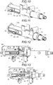
- Figs. 9 and 10 illustrate a positional relationship between the upper shaft 2x, the column housing 3, the outer tube 10, the inner tube 20, and the holding member 30 in a state where the steering wheel SW is adjusted to the rearmost position of the vehicle body, that is, an operation position closest to a driver, and in a state where the steering wheel SW is adjusted to the frontmost position of the vehicle body, that is, an operation position most distant from the driver, respectively.
- the rear end face of the holding member 30 is abutted on the opening 10b of the outer tube 10, and thus the column tube 1 is locked at the rearmost position.
- the state of the whole steering device at this time is illustrated in Fig. 12 . Meanwhile, in Fig.
- the front end face of the holding member 30 is abutted on the opening 10b of the outer tube 10, and the column tube 1 is locked at the frontmost position.
- the holding member 30 is arranged not to be abutted on the opening 3b of the column housing 3, but may be configured to be abutted on the opening 3b.
- the energy absorption operation in the embodiment is performed as follows. For example, in a normal state illustrated in Fig. 2 , when a load equal to or larger than a predetermined value is applied to the steering wheel SW from the rear side, the outer tube 10 integrally connected to the upper shaft 2x moves with respect to the inner tube 20 in the axial direction. That is, the outer tube 10, together with the steering shaft 2 and the steering wheel SW, moves forward from a position in the normal state illustrated in Fig. 2 , moves to a predetermined stop position, and is placed in, for example, a state illustrated in Fig. 11 . In the meantime, energy generated by an excessive load applied to the steering wheel SW toward the front side of the vehicle is properly absorbed by the movement of the outer tube 10, the steering shaft 2, and the steering wheel SW.
- the inner tube 20 may be made thin or small in diameter, and the weight thereof may be reduced.
- a low specific gravity material such as an aluminum alloy may be used, and a synthetic resin may also be used.
- a synthetic resin may also be used.
Landscapes
- Engineering & Computer Science (AREA)
- Chemical & Material Sciences (AREA)
- Combustion & Propulsion (AREA)
- Transportation (AREA)
- Mechanical Engineering (AREA)
- Steering Controls (AREA)
Claims (8)
- Lenkvorrichtung eines Fahrzeugs mit
einem durch einen Fahrzeugkörper (VB) abgestützten Säulengehäuse (3);
einem bezüglich des Säulengehäuses in einer Axialrichtung bewegbar abgestützten und zur Aufnahme einer Lenkwelle (2) eingerichteten Säulenrohr (1); und
einer Teleskopmechanik (4), welche eingerichtet ist, das Säulenrohr bezüglich des Säulengehäuses in der Axialrichtung anzutreiben,
wobei das Säulenrohr
ein Außenrohr (10), welches eingerichtet ist, die Lenkwelle aufzunehmen und die Lenkwelle um eine Achse der Lenkwelle drehbar abzustützen, und
ein Innenrohr (20), welches in dem Außenrohr aufgenommen ist, beinhaltet und
das Säulenrohr eingerichtet ist, eine Relativbewegung des Außenrohrs bezüglich des Innenrohrs in der Axialrichtung zu erlauben, wenn eine Last, welche gleich oder größer als ein vorbestimmter Wert ist, auf die Lenkwelle aufgebracht ist, und
die Teleskopmechanik
ein Halteelement (30) und
eine Antriebsmechanik (40), welche mit dem Halteelement verbunden ist und durch das Säulengehäuse abgestützt ist, um das Halteelement in der Axialrichtung anzutreiben, beinhaltet und
die Teleskopmechanik eingerichtet ist, das Innenrohr und das Außenrohr bezüglich des Säulengehäuses in der Axialrichtung durch die Antriebsmechanik anzutreiben,
dadurch gekennzeichnet, dass
das Innenrohr (20) eingerichtet ist, das Außenrohr (10) in einem Normalzustand bei einer vorbestimmten Position zu halten, und das Halteelement (30) durch das Innenrohr (20) abgestützt ist. - Lenkvorrichtung des Fahrzeugs nach Anspruch 1 weiterhin mit einem Lagerelement (12x, 12y), welches zwischen dem Außenrohr und der Lenkwelle eingefügt ist, um die drehbare Abstützung der Lenkwelle bezüglich des Außenrohrs zu erlauben und eine Relativbewegung der Lenkwelle in der Axialrichtung zu verhindern.
- Lenkvorrichtung des Fahrzeugs nach Anspruch 1 oder 2 weiterhin mit einem Federelement (13), welches zwischen dem Innenrohr und dem Außenrohr eingefügt ist, um eine Relativbewegung zwischen dem Innenrohr und dem Außenrohr in der Axialrichtung zu beschränken.
- Lenkvorrichtung des Fahrzeugs nach einem der Ansprüche 1 bis 3,
wobei das Außenrohr eine Öffnung (10a, 10b) hat, welche dem Halteelement erlaubt, sich in der Axialrichtung zu bewegen, und das Halteelement zur Verbindung mit der Antriebsmechanik durch die Öffnung eingesetzt ist. - Lenkvorrichtung des Fahrzeugs nach Anspruch 4,
wobei die Öffnung des Außenrohrs eine Öffnung ist, deren Längsrichtung mit einer Axialrichtung des Außenrohrs fluchtet, und eingerichtet ist, eine Bewegung des Halteelements in der Axialrichtung an beiden Endabschnitten der Öffnung zu verhindern. - Lenkvorrichtung des Fahrzeugs nach einem der Ansprüche 4 oder 5,
wobei das Halteelement durch eine Seite des Innenrohrs eingesetzt ist und zur Verbindung mit der Antriebsmechanik durch eine andere Seite des Innenrohrs abgestützt ist. - Lenkvorrichtung des Fahrzeugs nach Anspruch 6,
wobei das Halteelement als ein Rohrkörper mit einem Flanschabschnitt (31) an einem Ende davon eingerichtet ist,
das Innenrohr eine erste Öffnung (20a), welche an der einen Seite des Innenrohrs ausgebildet ist und durch welche das Halteelement eingesetzt ist, und eine zweite Öffnung (20b), welche an der anderen Seite des Innenrohrs bei einer der ersten Öffnung gegenüberliegenden Position ausgebildet ist, beinhaltet und eine in dem Innenrohr ausgebildete Ringnut (20c) hat, und
das Halteelement durch die zweite Öffnung eingesetzt ist, so dass der Flanschabschnitt in die Ringnut eingepasst ist. - Lenkvorrichtung des Fahrzeugs nach einem der Ansprüche 1 bis 7,
wobei die Antriebsmechanik
einen durch das Säulengehäuse abgestützten Elektromotor (41),
eine mit einer Ausgangswelle des Elektromotors verbundene Gewindespindel (43), und
ein mit der Gewindespindel verschraubtes und durch das Halteelement gehaltenes Mutterelement (44) beinhaltet, und
sich das Mutterelement gemäß einem Drehantrieb der Gewindespindel durch den Elektromotor in einer Axialrichtung der Gewindespindel bewegt und sich das Halteelement zusammen mit dem Mutterelement in der Axialrichtung bewegt, so dass sich das Säulenrohr in einer Vorwärts-Rückwärts-Richtung eines Fahrzeugkörpers bewegt.
Applications Claiming Priority (1)
| Application Number | Priority Date | Filing Date | Title |
|---|---|---|---|
| JP2016184888A JP6738536B2 (ja) | 2016-09-21 | 2016-09-21 | 車両のステアリング装置 |
Publications (2)
| Publication Number | Publication Date |
|---|---|
| EP3299254A1 EP3299254A1 (de) | 2018-03-28 |
| EP3299254B1 true EP3299254B1 (de) | 2019-04-17 |
Family
ID=59276581
Family Applications (1)
| Application Number | Title | Priority Date | Filing Date |
|---|---|---|---|
| EP17179270.8A Not-in-force EP3299254B1 (de) | 2016-09-21 | 2017-07-03 | Lenkvorrichtung eines fahrzeugs |
Country Status (4)
| Country | Link |
|---|---|
| US (1) | US10479394B2 (de) |
| EP (1) | EP3299254B1 (de) |
| JP (1) | JP6738536B2 (de) |
| CN (1) | CN207292112U (de) |
Families Citing this family (16)
| Publication number | Priority date | Publication date | Assignee | Title |
|---|---|---|---|---|
| DE102015000029A1 (de) * | 2015-01-08 | 2016-07-14 | Thyssenkrupp Ag | Lenksäule mit adaptierbarer Schwenklagerung |
| KR102274121B1 (ko) * | 2017-04-03 | 2021-07-06 | 현대자동차주식회사 | 자동차용 전동식 스티어링 컬럼 장치 |
| JP7060986B2 (ja) | 2018-03-15 | 2022-04-27 | 株式会社クレハ | バインダー組成物、非水電解質二次電池用電極を製造するための合剤、非水電解質二次電池用の電極および非水電解質二次電池 |
| US11498603B2 (en) * | 2018-05-31 | 2022-11-15 | Byd Company Limited | Steering column and vehicle |
| DE102018212738A1 (de) * | 2018-07-31 | 2020-02-06 | Brose Fahrzeugteile Gmbh & Co. Kommanditgesellschaft, Coburg | Elektromotorisch verstellbare Lenkvorrichtung |
| KR102111357B1 (ko) * | 2018-09-21 | 2020-05-15 | 주식회사 만도 | 차량의 조향 컬럼 |
| KR102917558B1 (ko) * | 2020-02-11 | 2026-01-27 | 남양넥스모 주식회사 | 슬라이딩 구조를 가지는 차량용 스티어링 컬럼 구조 |
| CN111516748B (zh) * | 2020-05-09 | 2021-08-27 | 安徽江淮汽车集团股份有限公司 | 转向系统及车辆 |
| CN112109796A (zh) * | 2020-10-12 | 2020-12-22 | 坤泰车辆系统(常州)有限公司 | 自动驾驶车辆转向管柱 |
| KR102901299B1 (ko) * | 2021-04-07 | 2025-12-17 | 에이치엘만도 주식회사 | 차량의 조향 컬럼 |
| DE112022000250T5 (de) | 2021-04-07 | 2023-09-28 | Hl Mando Corporation | Lenksäule für ein fahrzeug |
| WO2022269932A1 (ja) * | 2021-06-25 | 2022-12-29 | 株式会社ジェイテクト | ステアリングコラム装置 |
| KR102670839B1 (ko) * | 2021-11-16 | 2024-05-30 | 에이치엘만도 주식회사 | 스티어링 장치 |
| US11999407B1 (en) * | 2023-02-21 | 2024-06-04 | Ford Global Technologies, Llc | Translating steering column with reduced packaging space |
| KR20240143435A (ko) * | 2023-03-24 | 2024-10-02 | 에이치엘만도 주식회사 | 자동차의 조향장치 |
| KR102938441B1 (ko) * | 2023-03-31 | 2026-03-13 | 에이치엘만도 주식회사 | 자동차의 조향장치 |
Family Cites Families (11)
| Publication number | Priority date | Publication date | Assignee | Title |
|---|---|---|---|---|
| JP2006044545A (ja) * | 2004-08-06 | 2006-02-16 | Nsk Ltd | ステアリングコラム装置 |
| JP2006069360A (ja) * | 2004-09-01 | 2006-03-16 | Nsk Ltd | ステアリングコラム装置 |
| JP2007112274A (ja) * | 2005-10-20 | 2007-05-10 | Nsk Ltd | ステアリング装置 |
| JP4868213B2 (ja) * | 2005-12-21 | 2012-02-01 | アイシン精機株式会社 | エネルギー吸収ステアリングコラム |
| JP2008087582A (ja) * | 2006-09-29 | 2008-04-17 | Nsk Ltd | 電動テレスコ調整式ステアリング装置 |
| JP2009298298A (ja) * | 2008-06-13 | 2009-12-24 | Aisin Seiki Co Ltd | ステアリング装置 |
| JP5369537B2 (ja) | 2008-08-08 | 2013-12-18 | アイシン精機株式会社 | エネルギー吸収ステアリングコラム |
| CN102233897A (zh) * | 2010-04-23 | 2011-11-09 | C.劳勃.汉默斯坦两合有限公司 | 用于机动车的长度可调节的转向柱模块 |
| JP6179347B2 (ja) | 2013-10-25 | 2017-08-16 | アイシン精機株式会社 | 車両のステアリング装置 |
| JP6417796B2 (ja) * | 2014-09-02 | 2018-11-07 | アイシン精機株式会社 | ステアリング装置 |
| JP2016055689A (ja) * | 2014-09-08 | 2016-04-21 | 富士機工株式会社 | 電動式ステアリングコラム装置 |
-
2016
- 2016-09-21 JP JP2016184888A patent/JP6738536B2/ja not_active Expired - Fee Related
-
2017
- 2017-07-03 EP EP17179270.8A patent/EP3299254B1/de not_active Not-in-force
- 2017-08-24 US US15/685,196 patent/US10479394B2/en active Active
- 2017-08-31 CN CN201721113473.8U patent/CN207292112U/zh active Active
Non-Patent Citations (1)
| Title |
|---|
| None * |
Also Published As
| Publication number | Publication date |
|---|---|
| CN207292112U (zh) | 2018-05-01 |
| EP3299254A1 (de) | 2018-03-28 |
| JP2018047809A (ja) | 2018-03-29 |
| US20180079445A1 (en) | 2018-03-22 |
| US10479394B2 (en) | 2019-11-19 |
| JP6738536B2 (ja) | 2020-08-12 |
Similar Documents
| Publication | Publication Date | Title |
|---|---|---|
| EP3299254B1 (de) | Lenkvorrichtung eines fahrzeugs | |
| US8161839B2 (en) | Electrically powered tilt steering device | |
| EP2572959B1 (de) | Lenkvorrichtung für Fahrzeug | |
| CN102826112B (zh) | 转向装置 | |
| US20120247259A1 (en) | Steering apparatus for vehicle | |
| US8485554B2 (en) | Steering device | |
| CN102625761B (zh) | 转向柱用支承装置 | |
| US20130074639A1 (en) | Steering apparatus for vehicle | |
| CN101380965A (zh) | 转向柱装置 | |
| CN107614356A (zh) | 可伸缩式转向装置 | |
| US9010806B2 (en) | Steering system | |
| JPWO2007046436A1 (ja) | ステアリングコラム装置 | |
| WO2022269932A1 (ja) | ステアリングコラム装置 | |
| JP5811735B2 (ja) | 車両のステアリング装置 | |
| JP2012144058A (ja) | ステアリング装置 | |
| US20250121879A1 (en) | Rotation-limiting device and steering device | |
| JP2014015120A (ja) | 電動パワーステアリング装置 | |
| JP5970989B2 (ja) | 電動パワーステアリング装置 | |
| JP5970991B2 (ja) | 電動パワーステアリング装置 | |
| JP5966700B2 (ja) | 電動パワーステアリング装置 | |
| JP2018052210A (ja) | 車両のステアリング装置 | |
| JP4454799B2 (ja) | 電動パワーステアリング装置 | |
| KR20120134363A (ko) | 자동차의 조향 컬럼 | |
| JP5012226B2 (ja) | テレスコピック式ステアリング装置 | |
| KR20120083012A (ko) | 자동차의 조향 컬럼 |
Legal Events
| Date | Code | Title | Description |
|---|---|---|---|
| PUAI | Public reference made under article 153(3) epc to a published international application that has entered the european phase |
Free format text: ORIGINAL CODE: 0009012 |
|
| STAA | Information on the status of an ep patent application or granted ep patent |
Free format text: STATUS: THE APPLICATION HAS BEEN PUBLISHED |
|
| AK | Designated contracting states |
Kind code of ref document: A1 Designated state(s): AL AT BE BG CH CY CZ DE DK EE ES FI FR GB GR HR HU IE IS IT LI LT LU LV MC MK MT NL NO PL PT RO RS SE SI SK SM TR |
|
| AX | Request for extension of the european patent |
Extension state: BA ME |
|
| STAA | Information on the status of an ep patent application or granted ep patent |
Free format text: STATUS: REQUEST FOR EXAMINATION WAS MADE |
|
| 17P | Request for examination filed |
Effective date: 20180926 |
|
| RBV | Designated contracting states (corrected) |
Designated state(s): AL AT BE BG CH CY CZ DE DK EE ES FI FR GB GR HR HU IE IS IT LI LT LU LV MC MK MT NL NO PL PT RO RS SE SI SK SM TR |
|
| GRAP | Despatch of communication of intention to grant a patent |
Free format text: ORIGINAL CODE: EPIDOSNIGR1 |
|
| STAA | Information on the status of an ep patent application or granted ep patent |
Free format text: STATUS: GRANT OF PATENT IS INTENDED |
|
| RAP1 | Party data changed (applicant data changed or rights of an application transferred) |
Owner name: AISIN SEIKI KABUSHIKI KAISHA |
|
| RIN1 | Information on inventor provided before grant (corrected) |
Inventor name: KATO, KEN |
|
| INTG | Intention to grant announced |
Effective date: 20181119 |
|
| GRAS | Grant fee paid |
Free format text: ORIGINAL CODE: EPIDOSNIGR3 |
|
| GRAA | (expected) grant |
Free format text: ORIGINAL CODE: 0009210 |
|
| STAA | Information on the status of an ep patent application or granted ep patent |
Free format text: STATUS: THE PATENT HAS BEEN GRANTED |
|
| AK | Designated contracting states |
Kind code of ref document: B1 Designated state(s): AL AT BE BG CH CY CZ DE DK EE ES FI FR GB GR HR HU IE IS IT LI LT LU LV MC MK MT NL NO PL PT RO RS SE SI SK SM TR |
|
| REG | Reference to a national code |
Ref country code: GB Ref legal event code: FG4D |
|
| REG | Reference to a national code |
Ref country code: CH Ref legal event code: EP |
|
| REG | Reference to a national code |
Ref country code: DE Ref legal event code: R096 Ref document number: 602017003320 Country of ref document: DE |
|
| REG | Reference to a national code |
Ref country code: AT Ref legal event code: REF Ref document number: 1121219 Country of ref document: AT Kind code of ref document: T Effective date: 20190515 Ref country code: IE Ref legal event code: FG4D |
|
| REG | Reference to a national code |
Ref country code: NL Ref legal event code: MP Effective date: 20190417 |
|
| REG | Reference to a national code |
Ref country code: LT Ref legal event code: MG4D |
|
| PG25 | Lapsed in a contracting state [announced via postgrant information from national office to epo] |
Ref country code: NL Free format text: LAPSE BECAUSE OF FAILURE TO SUBMIT A TRANSLATION OF THE DESCRIPTION OR TO PAY THE FEE WITHIN THE PRESCRIBED TIME-LIMIT Effective date: 20190417 |
|
| PG25 | Lapsed in a contracting state [announced via postgrant information from national office to epo] |
Ref country code: SE Free format text: LAPSE BECAUSE OF FAILURE TO SUBMIT A TRANSLATION OF THE DESCRIPTION OR TO PAY THE FEE WITHIN THE PRESCRIBED TIME-LIMIT Effective date: 20190417 Ref country code: ES Free format text: LAPSE BECAUSE OF FAILURE TO SUBMIT A TRANSLATION OF THE DESCRIPTION OR TO PAY THE FEE WITHIN THE PRESCRIBED TIME-LIMIT Effective date: 20190417 Ref country code: LT Free format text: LAPSE BECAUSE OF FAILURE TO SUBMIT A TRANSLATION OF THE DESCRIPTION OR TO PAY THE FEE WITHIN THE PRESCRIBED TIME-LIMIT Effective date: 20190417 Ref country code: AL Free format text: LAPSE BECAUSE OF FAILURE TO SUBMIT A TRANSLATION OF THE DESCRIPTION OR TO PAY THE FEE WITHIN THE PRESCRIBED TIME-LIMIT Effective date: 20190417 Ref country code: PT Free format text: LAPSE BECAUSE OF FAILURE TO SUBMIT A TRANSLATION OF THE DESCRIPTION OR TO PAY THE FEE WITHIN THE PRESCRIBED TIME-LIMIT Effective date: 20190817 Ref country code: NO Free format text: LAPSE BECAUSE OF FAILURE TO SUBMIT A TRANSLATION OF THE DESCRIPTION OR TO PAY THE FEE WITHIN THE PRESCRIBED TIME-LIMIT Effective date: 20190717 Ref country code: HR Free format text: LAPSE BECAUSE OF FAILURE TO SUBMIT A TRANSLATION OF THE DESCRIPTION OR TO PAY THE FEE WITHIN THE PRESCRIBED TIME-LIMIT Effective date: 20190417 Ref country code: FI Free format text: LAPSE BECAUSE OF FAILURE TO SUBMIT A TRANSLATION OF THE DESCRIPTION OR TO PAY THE FEE WITHIN THE PRESCRIBED TIME-LIMIT Effective date: 20190417 |
|
| PG25 | Lapsed in a contracting state [announced via postgrant information from national office to epo] |
Ref country code: GR Free format text: LAPSE BECAUSE OF FAILURE TO SUBMIT A TRANSLATION OF THE DESCRIPTION OR TO PAY THE FEE WITHIN THE PRESCRIBED TIME-LIMIT Effective date: 20190718 Ref country code: BG Free format text: LAPSE BECAUSE OF FAILURE TO SUBMIT A TRANSLATION OF THE DESCRIPTION OR TO PAY THE FEE WITHIN THE PRESCRIBED TIME-LIMIT Effective date: 20190717 Ref country code: PL Free format text: LAPSE BECAUSE OF FAILURE TO SUBMIT A TRANSLATION OF THE DESCRIPTION OR TO PAY THE FEE WITHIN THE PRESCRIBED TIME-LIMIT Effective date: 20190417 Ref country code: RS Free format text: LAPSE BECAUSE OF FAILURE TO SUBMIT A TRANSLATION OF THE DESCRIPTION OR TO PAY THE FEE WITHIN THE PRESCRIBED TIME-LIMIT Effective date: 20190417 Ref country code: LV Free format text: LAPSE BECAUSE OF FAILURE TO SUBMIT A TRANSLATION OF THE DESCRIPTION OR TO PAY THE FEE WITHIN THE PRESCRIBED TIME-LIMIT Effective date: 20190417 |
|
| REG | Reference to a national code |
Ref country code: AT Ref legal event code: MK05 Ref document number: 1121219 Country of ref document: AT Kind code of ref document: T Effective date: 20190417 |
|
| PG25 | Lapsed in a contracting state [announced via postgrant information from national office to epo] |
Ref country code: IS Free format text: LAPSE BECAUSE OF FAILURE TO SUBMIT A TRANSLATION OF THE DESCRIPTION OR TO PAY THE FEE WITHIN THE PRESCRIBED TIME-LIMIT Effective date: 20190817 |
|
| REG | Reference to a national code |
Ref country code: DE Ref legal event code: R097 Ref document number: 602017003320 Country of ref document: DE |
|
| PG25 | Lapsed in a contracting state [announced via postgrant information from national office to epo] |
Ref country code: EE Free format text: LAPSE BECAUSE OF FAILURE TO SUBMIT A TRANSLATION OF THE DESCRIPTION OR TO PAY THE FEE WITHIN THE PRESCRIBED TIME-LIMIT Effective date: 20190417 Ref country code: AT Free format text: LAPSE BECAUSE OF FAILURE TO SUBMIT A TRANSLATION OF THE DESCRIPTION OR TO PAY THE FEE WITHIN THE PRESCRIBED TIME-LIMIT Effective date: 20190417 Ref country code: DK Free format text: LAPSE BECAUSE OF FAILURE TO SUBMIT A TRANSLATION OF THE DESCRIPTION OR TO PAY THE FEE WITHIN THE PRESCRIBED TIME-LIMIT Effective date: 20190417 Ref country code: SK Free format text: LAPSE BECAUSE OF FAILURE TO SUBMIT A TRANSLATION OF THE DESCRIPTION OR TO PAY THE FEE WITHIN THE PRESCRIBED TIME-LIMIT Effective date: 20190417 Ref country code: CZ Free format text: LAPSE BECAUSE OF FAILURE TO SUBMIT A TRANSLATION OF THE DESCRIPTION OR TO PAY THE FEE WITHIN THE PRESCRIBED TIME-LIMIT Effective date: 20190417 Ref country code: RO Free format text: LAPSE BECAUSE OF FAILURE TO SUBMIT A TRANSLATION OF THE DESCRIPTION OR TO PAY THE FEE WITHIN THE PRESCRIBED TIME-LIMIT Effective date: 20190417 |
|
| PLBE | No opposition filed within time limit |
Free format text: ORIGINAL CODE: 0009261 |
|
| STAA | Information on the status of an ep patent application or granted ep patent |
Free format text: STATUS: NO OPPOSITION FILED WITHIN TIME LIMIT |
|
| PG25 | Lapsed in a contracting state [announced via postgrant information from national office to epo] |
Ref country code: MC Free format text: LAPSE BECAUSE OF FAILURE TO SUBMIT A TRANSLATION OF THE DESCRIPTION OR TO PAY THE FEE WITHIN THE PRESCRIBED TIME-LIMIT Effective date: 20190417 Ref country code: IT Free format text: LAPSE BECAUSE OF FAILURE TO SUBMIT A TRANSLATION OF THE DESCRIPTION OR TO PAY THE FEE WITHIN THE PRESCRIBED TIME-LIMIT Effective date: 20190417 Ref country code: SM Free format text: LAPSE BECAUSE OF FAILURE TO SUBMIT A TRANSLATION OF THE DESCRIPTION OR TO PAY THE FEE WITHIN THE PRESCRIBED TIME-LIMIT Effective date: 20190417 |
|
| 26N | No opposition filed |
Effective date: 20200120 |
|
| PG25 | Lapsed in a contracting state [announced via postgrant information from national office to epo] |
Ref country code: TR Free format text: LAPSE BECAUSE OF FAILURE TO SUBMIT A TRANSLATION OF THE DESCRIPTION OR TO PAY THE FEE WITHIN THE PRESCRIBED TIME-LIMIT Effective date: 20190417 |
|
| REG | Reference to a national code |
Ref country code: BE Ref legal event code: MM Effective date: 20190731 |
|
| PG25 | Lapsed in a contracting state [announced via postgrant information from national office to epo] |
Ref country code: LU Free format text: LAPSE BECAUSE OF NON-PAYMENT OF DUE FEES Effective date: 20190703 Ref country code: SI Free format text: LAPSE BECAUSE OF FAILURE TO SUBMIT A TRANSLATION OF THE DESCRIPTION OR TO PAY THE FEE WITHIN THE PRESCRIBED TIME-LIMIT Effective date: 20190417 Ref country code: BE Free format text: LAPSE BECAUSE OF NON-PAYMENT OF DUE FEES Effective date: 20190731 |
|
| PG25 | Lapsed in a contracting state [announced via postgrant information from national office to epo] |
Ref country code: FR Free format text: LAPSE BECAUSE OF NON-PAYMENT OF DUE FEES Effective date: 20190731 |
|
| PG25 | Lapsed in a contracting state [announced via postgrant information from national office to epo] |
Ref country code: IE Free format text: LAPSE BECAUSE OF NON-PAYMENT OF DUE FEES Effective date: 20190703 |
|
| REG | Reference to a national code |
Ref country code: CH Ref legal event code: PL |
|
| PG25 | Lapsed in a contracting state [announced via postgrant information from national office to epo] |
Ref country code: CH Free format text: LAPSE BECAUSE OF NON-PAYMENT OF DUE FEES Effective date: 20200731 Ref country code: LI Free format text: LAPSE BECAUSE OF NON-PAYMENT OF DUE FEES Effective date: 20200731 |
|
| PG25 | Lapsed in a contracting state [announced via postgrant information from national office to epo] |
Ref country code: CY Free format text: LAPSE BECAUSE OF FAILURE TO SUBMIT A TRANSLATION OF THE DESCRIPTION OR TO PAY THE FEE WITHIN THE PRESCRIBED TIME-LIMIT Effective date: 20190417 |
|
| PG25 | Lapsed in a contracting state [announced via postgrant information from national office to epo] |
Ref country code: MT Free format text: LAPSE BECAUSE OF FAILURE TO SUBMIT A TRANSLATION OF THE DESCRIPTION OR TO PAY THE FEE WITHIN THE PRESCRIBED TIME-LIMIT Effective date: 20190417 Ref country code: HU Free format text: LAPSE BECAUSE OF FAILURE TO SUBMIT A TRANSLATION OF THE DESCRIPTION OR TO PAY THE FEE WITHIN THE PRESCRIBED TIME-LIMIT; INVALID AB INITIO Effective date: 20170703 |
|
| GBPC | Gb: european patent ceased through non-payment of renewal fee |
Effective date: 20210703 |
|
| PG25 | Lapsed in a contracting state [announced via postgrant information from national office to epo] |
Ref country code: GB Free format text: LAPSE BECAUSE OF NON-PAYMENT OF DUE FEES Effective date: 20210703 |
|
| PG25 | Lapsed in a contracting state [announced via postgrant information from national office to epo] |
Ref country code: MK Free format text: LAPSE BECAUSE OF FAILURE TO SUBMIT A TRANSLATION OF THE DESCRIPTION OR TO PAY THE FEE WITHIN THE PRESCRIBED TIME-LIMIT Effective date: 20190417 |
|
| PGFP | Annual fee paid to national office [announced via postgrant information from national office to epo] |
Ref country code: DE Payment date: 20240529 Year of fee payment: 8 |
|
| REG | Reference to a national code |
Ref country code: DE Ref legal event code: R119 Ref document number: 602017003320 Country of ref document: DE |
|
| PG25 | Lapsed in a contracting state [announced via postgrant information from national office to epo] |
Ref country code: DE Free format text: LAPSE BECAUSE OF NON-PAYMENT OF DUE FEES Effective date: 20260203 |