EP3299102B1 - Werkzeugkörper in kombination mit einem ersten schneideinsatz und einem zweiten schneideinsatz - Google Patents
Werkzeugkörper in kombination mit einem ersten schneideinsatz und einem zweiten schneideinsatz Download PDFInfo
- Publication number
- EP3299102B1 EP3299102B1 EP16796505.2A EP16796505A EP3299102B1 EP 3299102 B1 EP3299102 B1 EP 3299102B1 EP 16796505 A EP16796505 A EP 16796505A EP 3299102 B1 EP3299102 B1 EP 3299102B1
- Authority
- EP
- European Patent Office
- Prior art keywords
- cutting
- wall surface
- side wall
- tool body
- insert
- Prior art date
- Legal status (The legal status is an assumption and is not a legal conclusion. Google has not performed a legal analysis and makes no representation as to the accuracy of the status listed.)
- Active
Links
Images


Classifications
-
- B—PERFORMING OPERATIONS; TRANSPORTING
- B23—MACHINE TOOLS; METAL-WORKING NOT OTHERWISE PROVIDED FOR
- B23C—MILLING
- B23C5/00—Milling-cutters
- B23C5/02—Milling-cutters characterised by the shape of the cutter
- B23C5/10—Shank-type cutters, i.e. with an integral shaft
- B23C5/109—Shank-type cutters, i.e. with an integral shaft with removable cutting inserts
-
- B—PERFORMING OPERATIONS; TRANSPORTING
- B23—MACHINE TOOLS; METAL-WORKING NOT OTHERWISE PROVIDED FOR
- B23C—MILLING
- B23C5/00—Milling-cutters
- B23C5/16—Milling-cutters characterised by physical features other than shape
- B23C5/20—Milling-cutters characterised by physical features other than shape with removable cutter bits or teeth or cutting inserts
- B23C5/22—Securing arrangements for bits or teeth or cutting inserts
- B23C5/2204—Securing arrangements for bits or teeth or cutting inserts with cutting inserts clamped against the walls of the recess in the cutter body by a clamping member acting upon the wall of a hole in the insert
- B23C5/2208—Securing arrangements for bits or teeth or cutting inserts with cutting inserts clamped against the walls of the recess in the cutter body by a clamping member acting upon the wall of a hole in the insert for plate-like cutting inserts
- B23C5/2213—Securing arrangements for bits or teeth or cutting inserts with cutting inserts clamped against the walls of the recess in the cutter body by a clamping member acting upon the wall of a hole in the insert for plate-like cutting inserts having a special shape
-
- B—PERFORMING OPERATIONS; TRANSPORTING
- B23—MACHINE TOOLS; METAL-WORKING NOT OTHERWISE PROVIDED FOR
- B23C—MILLING
- B23C5/00—Milling-cutters
- B23C5/16—Milling-cutters characterised by physical features other than shape
- B23C5/20—Milling-cutters characterised by physical features other than shape with removable cutter bits or teeth or cutting inserts
- B23C5/22—Securing arrangements for bits or teeth or cutting inserts
- B23C5/24—Securing arrangements for bits or teeth or cutting inserts adjustable
- B23C5/2472—Securing arrangements for bits or teeth or cutting inserts adjustable the adjusting means being screws
-
- B—PERFORMING OPERATIONS; TRANSPORTING
- B23—MACHINE TOOLS; METAL-WORKING NOT OTHERWISE PROVIDED FOR
- B23C—MILLING
- B23C2200/00—Details of milling cutting inserts
- B23C2200/04—Overall shape
- B23C2200/0405—Hexagonal
- B23C2200/0411—Hexagonal irregular
-
- B—PERFORMING OPERATIONS; TRANSPORTING
- B23—MACHINE TOOLS; METAL-WORKING NOT OTHERWISE PROVIDED FOR
- B23C—MILLING
- B23C2210/00—Details of milling cutters
- B23C2210/16—Fixation of inserts or cutting bits in the tool
-
- B—PERFORMING OPERATIONS; TRANSPORTING
- B23—MACHINE TOOLS; METAL-WORKING NOT OTHERWISE PROVIDED FOR
- B23C—MILLING
- B23C2210/00—Details of milling cutters
- B23C2210/16—Fixation of inserts or cutting bits in the tool
- B23C2210/168—Seats for cutting inserts, supports for replacable cutting bits
Definitions
- the present invention relates to a tool body in combination with a first cutting insert and a second cutting insert having different shapes according to the preamble of independent claim 1, such a combination being known from document US 8 807 884 B2 .
- Patent Document 1 Conventionally, the tool disclosed in Patent Document 1 (below) has been used as an indexable rotary cutting tool for machining a three-dimensional shape of a die, etc.
- the cutting insert disclosed in Patent Document 1 has a cutting edge shape which allows for machining with a reduced amount of cutting depth and an increased feed speed, i.e., high-feed machining.
- this cutting insert is suited to roughing on a workpiece with high efficiency.
- Patent Document 2 an example of another indexable rotary cutting tool for machining a three-dimensional shape is disclosed in Patent Document 2.
- the cutting insert disclosed in Patent Document 2 has a substantially circular-arc shape in which, in a top view, a cutting edge thereof is projected outward.
- An indexable rotary cutting tool having a cutting insert which has the above edge shape mounted thereon is generally referred to as a radius cutter (or a radius end mill).
- a radius cutter a substantially circular-arc-shaped cutting edge thereof is capable of cutting, with high accuracy, a workpiece surface to be machined in three-dimensional machining, such as copy machining, and therefore, such radius cutter is suited not only to roughing but also to finishing.
- an angle of depth is set so as to be extremely small and a major cutting edge is substantially linear in a top view, in order to achieve high-feed machining in an indexable rotary cutting tool, and therefore, such cutting insert is not suited to finishing.
- an amount of portions that remain uncut may be produced.
- the cutting insert of Patent Document 2 has a substantially circular-arc-shaped cutting edge for use in a radius cutter, and therefore, such cutting insert is suited to finishing.
- the cutting insert of Patent Document 2 is not suited to high-feed machining which is performed suitably in a cutting tool on which the cutting insert of Patent Document 1 is mounted.
- An object of the present invention is to provide a tool body on which a plurality of types of cutting inserts are capable of being removably mounted.
- the present invention provides a tool body in combination with a first cutting insert and a second cutting insert having different shapes according to independent claim 1.
- the present invention can provide a tool body on which a plurality of types of cutting inserts are capable of being removably mounted.
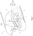
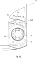
- a tool body 1 according to the present embodiment has, as its entire shape, a substantially cylindrical shape which has a rotational axis O defined so as to pass through the tool body 1 from a leading end 8 to a base end 9 thereof, as shown in Figs. 1 to 5 .
- two insert seats 2 are arranged at regular intervals in a circumferential direction around the rotational axis O.
- the number of insert seats 2 may be one or three or more.
- the plurality of insert seats 2 may be arranged at irregular intervals in the circumferential direction.
- These insert seats 2 are opened toward the leading end 8 of the tool body 1 and toward the outer periphery thereof, and such insert seats 2 have the same shape.
- a chip pocket 3 is formed so as to be adjacent to each insert seat 2.
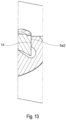
- Each insert seat 2 has a bottom wall surface 4 and a side wall surface 5.
- the bottom wall surface 4 is a surface formed so as to face forward in a tool rotating direction K around the rotational axis O.
- the side wall surface 5 is a surface formed so as to intersect with the bottom wall surface 4 at a desired angle.
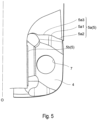
- the bottom wall surface 4 and the side wall surface 5 are not connected with each other, and recessed part 6 is formed therebetween. Therefore, in practice, a surface formed by extending the bottom wall surface 4 and a surface formed by extending the side wall surface 5 intersect with each other.
- the side wall surface 5 is constituted by a first side wall surface 5a facing toward the leading end 8 of the tool body 1 and a second side wall surface 5b facing toward the outer periphery of the tool body 1.
- the first side wall surface 5a and the second side wall surface 5b are not connected to each other and are arranged so as to be apart from each other.
- the bottom wall surface 4 is provided with a threaded hole 7.
- the bottom wall surface 4 is comprised of a single plane and has a shape and size which match the shape of a cutting insert to be mounted.
- the second side wall surface 5b is comprised of a single flat surface and has a substantially long rectangular shape in a direction in which the central axis O extends.
- the first side wall surface 5a is constituted by a combination of a plurality of types of surfaces. More specifically, the first side wall surface 5a is constituted by a first surface portion 5a1, a second surface portion 5a2 and a third surface portion 5a3.
- the third surface portion 5a3, the first surface portion 5a1 and the second surface portion 5a2 are placed in this order from the central axis O toward the outer periphery of the tool.
- the third surface portion 5a3 is located closest to the central axis O and is comprised of a single flat surface.
- the first surface portion 5a1 is connected to the third surface portion 5a3, and, as opposed to the third surface portion 5a3, the first surface portion 5a1 is comprised of a curved surface which is curved, in a recessed shape, toward the base end 9 of the tool body 1.
- the second surface portion 5a2 is comprised of a single flat surface connected, on the opposite side to a side to which the third surface portion 5a3 is connected, to the first surface portion 5a1. Therefore, the second surface portion 5a2 is located closest to the outer periphery.
- the first surface portion 5a1 is arranged at a position encompassing substantially a center area of the first side wall surface 5a as the insert seat 2 is viewed from a direction facing the bottom wall surface 4.
- substantially a center herein refers to an area near a center of the first side wall surface 5a in a direction substantially perpendicularly intersecting with the central axis O.
- the second side wall surface 5b has a positional relationship so as to be substantially parallel to the central axis O.
- the third surface portion 5a3 has a positional relationship so as to be substantially perpendicular to the central axis O.
- the second surface portion 5a2 is inclined relative to the central axis O such that a portion thereof closer to the outer periphery of the tool is closer to the leading end 8 of the tool.
- the first surface portion 5a1 is arranged so as to be inclined in its entirety such that a portion thereof connected to the second surface portion 5a2 is closer to the leading end 8 of the tool body 1 than a portion thereof connected to the third surface portion 5a3.
- the first cutting insert 11 comprises a first end surface 12 and a second end surface 13 which are substantially opposed to each other, i.e., which are arranged on substantially opposite sides from each other, and a peripheral side surface 14 which extends therebetween.
- the first end surface 12 and the second end surface 13 each have a substantially hexagonal shape in the plan view of Fig. 6 .
- such substantially hexagonal shape is a shape which is constituted by a substantially quadrangular portion indicated by the broken line in Fig. 6 and two substantially triangular portions 18 which are respectively joined to two opposing short sides of the substantially quadrangular portion 17.
- Each substantially triangular portion 18 has an isosceles triangular shape which is, in general, constituted by two linear oblique sides 18a and one linear base 18b.
- This base 18b corresponds to a short side of the substantially quadrangular portion 17. Therefore, the above-described substantially hexagonal shape can also be referred to as a shape in which the two substantially triangular portions 18 which do not share their bottoms 18b are connected with two substantially linear portions 19 (corresponding to long sides of the substantially quadrangular portion 17).
- a connecting part 18c between the two oblique sides 18a of the substantially triangular portion 18 has a circular arc shape.
- the two substantially triangular portions 18 have the same shape.
- the outer-shape portions which connect the two substantially triangular portions 18 are the substantially linear portions 19.
- the outer-shape portions are each not to be limited to having such shape.
- the outer portions may each be shaped so as to be projected outward of the cutting insert or shaped so as to be recessed inward of the cutting insert in a plan view, i.e., a top view.
- a reference axis A1 which penetrates substantially respective centers of the first end surface 12 and the second end surface 13 and which extend substantially perpendicularly to such end surfaces.
- the cutting insert 11 is formed so as to have a shape of 180-degree rotational symmetry, i.e., a shape of 2-fold rotational symmetry, about the reference axis A1.
- a mounting hole 16 is formed so as to penetrate the two end surfaces 12, 13, and the mounting hole 16 is arranged such that a central axis thereof matches the reference axis A1 of the cutting insert 11.
- the reference axis A1 extends perpendicularly to the first end surface 12.
- the first end surface 12 and the second end surface 13 are arranged so as to be substantially parallel to each other.
- the cutting insert 11 is formed so as to have the same shape when it is rotated by 180 degrees around an axis orthogonal to the reference axis A such that the two end surfaces 12, 13 are reversed. Further, the peripheral side surface 14 intersects substantially perpendicularly with the two end surfaces 12, 13. Accordingly, the cutting insert 11 of the present embodiment is of a so-called negative type with a clearance angle of 0 degrees.
- an intersecting edge between the peripheral side surface 14 and each of the first end surface 12 and the second end surface 13 is provided with cutting edges 15 along such intersecting edge.
- the cutting insert 11 of the present embodiment is of a double-sided use type in which both the first and second end surfaces 12, 13 can be used for cutting.
- the first end surface 12 serves as a rake surface
- the second end surface 13 serves as a seating surface
- the peripheral side surface 14 serves as a flank or a contact surface.
- the second end surface 13 serves as a rake surface
- the first end surface 12 serves as a seating surface
- the peripheral side surface 14 serves as a flank or a contact surface.
- the seating surface and the contact surface each refer to a surface having a portion which comes into contact with the insert seat 2 of the tool body 1.
- Each cutting edge 15 is associated with one of the substantially triangular portions 18 of the corresponding end surface.
- Each end surface has the two substantially triangular portions 18 and is thus provided with two cutting edges 15.
- Such two cutting edges 15 are arranged so as to be of 180-degree rotational symmetry about the reference axis A1.
- Each cutting edge 15 is, in general, constituted by two portions 15a, 15b.
- the linear cutting edge 15a a portion thereof corresponding to one of the oblique sides 18a of the substantially triangular portion 18 is referred to as the linear cutting edge 15a, and the connecting part 18c where the two oblique sides 18a of the substantially triangular portion 18 intersect with each other is referred to as the curved cutting edge 15b.
- the linear cutting edge 15a is configured so as to function as a major cutting edge which cuts a side wall surface serving as a workpiece surface to be machined.
- the curved cutting edge 15b is configured so as to function as a minor cutting edge which cuts a bottom wall surface serving as a workpiece surface to be machined.
- an interior angle ⁇ i.e., a corner angle
- an interior angle ⁇ which is formed by a tangent L2 of the minor cutting edge 15b on a bisector L1 of an interior angle of the minor cutting edge 15b and the major cutting edge 15a is 70 degrees.
- the corner angle ⁇ is preferably from 60 degrees to 80 degrees.
- each dimension of the cutting edge 15 is adjusted as appropriate in accordance with, for example, the shape of a workpiece.
- a virtual plane which is orthogonal to the reference axis A1 and which passes through the peripheral side surface 14 is defined as an intermediate plane M1.
- the intermediate plane M1 substantially divides the cutting insert 11 into halves.
- the linear cutting edge 15a extends, in general, so as to become more distant from the intermediate plane M1 as it heads away from the curved cutting edge 15b.
- the linear cutting edge 15a has a portion thereof most distant from the intermediate plane M1, in the vicinity of a portion thereof which intersects with the substantially linear portion 19.
- the curved cutting edge 15b extends so as to approach the intermediate plane M1 as it heads away from the linear cutting edge 15a.
- the other oblique side 18a which is not the oblique side 18a serving as the linear cutting edge 15a, extends so as to approach the intermediate plane M1 as it heads away from the adjacent curved cutting edge 15b.
- the cutting insert 11 is provided with two sets of cutting edges, i.e., the two cutting edges 15, on the first end surface 12 side. Therefore, when regarding one major cutting edge 15a and one minor cutting edge 15b as constituting one cutting edge section, the first and second end surfaces 12, 13 are each provided with two such cutting edge sections.
- the intersecting edge between the second end surface 13 and the peripheral side surface 14 is also provided with the cutting edges 15, as with the case of the first end surface 12.
- Each of the cutting edges 15 is formed so that the same shape is generated when the cutting insert 11 is rotated by 180 degrees around the axis orthogonal to the reference axis A1 such that the first end surface 12 and the second end surface 13 are reversed. In other words, a total of four sets of cutting edges 15 are formed. Accordingly, the cutting insert 11 is an economical insert since it can be used at least four times - twice by using the first end surface 12 side and twice by using the second end surface 13 side.
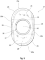
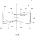
- the second cutting insert 21 comprises a first end surface 22 and a second end surface 23 which are substantially opposed to each other, i.e., which are arranged on substantially opposite sides from each other, and a peripheral side surface 24 which extends therebetween.
- the first end surface 22 and the second end surface 23 each have a substantially rounded quadrangular shape in the plan view of Fig. 9 .
- Such substantially rounded quadrangular shape is a shape which is constituted by a substantially quadrangular portion 27 indicated by the broken line in Fig. 9 and two substantially semicircular portions 28 which are respectively joined to two opposing sides of the substantially rounded quadrangular portion 27.
- the substantially rounded quadrangular shape is a shape in which the two substantially semicircular portions 28 which do not share their centers are connected with two substantially linear portions 29. Each substantially semicircular portion 28 is smoothly tangential to the substantially linear portions 29. Further, the two substantially semicircular portions 28 have the same shape.
- the outer-shape portions which connect the two substantially semicircular portions 28 are the substantially linear portions 29.
- the outer-shape portions are each not to be limited to having such shape.
- the outer portions may each be shaped so as to be projected outward of the cutting insert or shaped so as to be recessed inward of the cutting insert in a plan view, i.e., a top view.
- a reference axis A2 which penetrates substantially respective centers of the first end surface 22 and the second end surface 23 and which extend substantially perpendicularly to such end surfaces is defined.
- the cutting insert 21 is formed so as to have a shape of 180-degree rotational symmetry, i.e., a shape of 2-fold rotational symmetry, about the reference axis A2.
- centers of the respective circular arcs of the two substantially semicircular portions 28 are apart in the opposite directions by the same distance from the reference axis A2.
- the curvature radii of the circular arcs of the two substantially semicircular portions 28 are equal to each other.
- a mounting hole 26 is formed so as to penetrate the two end surfaces 22, 23, and the mounting hole 26 is arranged such that a central axis thereof matches the reference axis A2 of the cutting insert 21.
- the reference axis A2 extends perpendicularly to the first end surface 22.
- the first end surface 22 and the second end surface 23 are arranged so as to be substantially parallel to each other.
- the cutting insert 21 is formed so as to have the same shape when it is rotated by 180 degrees around an axis orthogonal to the reference axis A2 such that the two end surfaces 22, 23 are reversed. Further, the peripheral side surface 24 intersects substantially perpendicularly with the two end surfaces 22, 23. Accordingly, the cutting insert 21 of the present embodiment is of a so-called negative type with a clearance angle of 0 degrees.
- an intersecting edge between the peripheral side surface 24 and each of the first end surface 22 and the second end surface 23 is provided with cutting edges 25 along such intersecting edge.
- the cutting insert 21 of the present embodiment is of a double-sided use type in which both the first and second end surfaces 22, 23 can be used for cutting.
- the first end surface 22 serves as a rake surface
- the second end surface 23 serves as a seating surface
- the peripheral side surface 24 serves as a flank or a contact surface.
- the second end surface 23 serves as a rake surface
- the first end surface 22 serves as a seating surface
- the peripheral side surface 24 serves as a flank or a contact surface.
- the seating surface and the contact surface each refer to a surface having a portion which comes into contact with the insert seat 2 of the tool body 1.
- Each cutting edge 25 is, in general, constituted by two portions 25a, 25b.
- a contour shape of the first end surface 22 includes the substantially semicircular portions 28 and the substantially linear portions 29.
- a portion of the cutting edge 25 which corresponds to the substantially semicircular portion 28 is referred to as the circular-arc-shaped cutting edge 25a, and a portion of the cutting edge 25 which corresponds to the substantially linear portion 29 is referred to as the linear cutting edge 25b.
- the circular-arc-shaped cutting edge 25a is formed such that, in a plan view, the length thereof along the circular-arc-shaped cutting edge 25a is longer than the length of the linear cutting edge 25b.
- the cutting edge 25 is configured such that it is mainly the circular-arc-shaped cutting edge 25a that functions.
- a curvature radius R of the arc of the circular-arc-shaped cutting edge 25a is approximately 4 mm in a plan view.
- the configuration is not limited thereto.
- Each dimension of the cutting edge 25 is adjusted as appropriate in accordance with, for example, the shape of a workpiece.
- the cutting edge 25 may be formed throughout the intersecting edge of the first end surface 22 and the peripheral side surface 24 or may be formed through only part of such intersecting edge.
- each curved cutting edge 25a extends, in general, so as to become more distant from the intermediate plane M2 as it heads away from the linear cutting edge 25b.
- the curved cutting edge 25a has, at a position in the vicinity of a center thereof, a portion most distant from the intermediate plane M2. Further, the curved cutting edge 25a extends so as to approach the intermediate plane M2 as it heads away from the linear cutting edge 25b.
- the cutting insert 21 is provided with two sets of cutting edges, i.e., the two cutting edges 25, on the first end surface 22 side. Therefore, when regarding one circular-arc-shaped cutting edge 25a and one linear cutting edge 25b as constituting one cutting edge section, the upper and lower surfaces are each provided with two such cutting edge sections.
- the intersecting edge between the second end surface 23 and the peripheral side surface 24 is also provided with the cutting edges 25, as with the case of the first end surface 22.
- Each of the cutting edges 25 is formed so that the same shape is generated when the cutting insert 21 is rotated by 180 degrees around the axis orthogonal to the reference axis A2 such that the first end surface 22 and the second end surface 23 are reversed. In other words, a total of four sets of cutting edges 25 are formed. Accordingly, the cutting insert 21 is an economical insert since it can be used at least four times - twice by using the first end surface 22 side and twice by using the second end surface 23 side.
- the cutting inserts 11, 21 can each be made of hard materials, such as cemented carbide, cermet, ceramic, or an ultrahigh-pressure sintered body containing diamond or cubic boron nitride, or a material obtained by applying PVD or CVD coating to these materials.
- the first cutting insert 11 is removably mounted on the insert seat 2 of the tool body 1 by means of a clamping member 32 which is a mechanical mounting means.
- the indexable rotary cutting tool 31 of this embodiment employs a fastening screw as the clamping member 32.
- the clamping member 32 is not limited thereto.
- the cutting insert 11 is mounted on each of the insert seats 2 of the tool body 1.
- the second end surface 13 of the cutting insert 11 comes into contact with the bottom wall surface 4 of the insert seat 2, and the peripheral side surface 14 of the cutting insert 11 comes into contact with the side wall surface 5 of the insert seat 2.
- the peripheral side surface 14 comes into contact with the second side wall surface 5b in its entirety.
- the peripheral side surface 14 comes into contact with the second surface portion 5a2 only. In other words, the peripheral side surface 14 does not come into contact with the first surface portion 5a1 and the third surface portion 5a3 of the first side wall surface 5a.
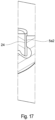
- the second cutting insert 21 is removably mounted on the insert seat 2 of the tool body 1 by means of the clamping member 32 which is a mechanical mounting means (being the same as that used when mounting the first cutting insert 11).
- the cutting insert 21 is mounted on each of the insert seats 2 of the tool body 1.
- This tool body 1 is the same as the tool body 1 on which the first cutting insert 11 has been mounted.
- the second end surface 23 of the cutting insert 21 comes into contact with the bottom wall surface 4 of the insert seat 2, and the peripheral side surface 24 of the cutting insert 21 comes into contact with the side wall surface 5 of the insert seat 2.
- the peripheral side surface 24 comes into contact with the second side wall surface 5b in its entirety.
- the peripheral side surface 24 comes into contact with the first surface portion 5a1 only.
- peripheral side surface 24 does not come into contact with the second surface portion 5a2 and the third surface portion 5a3 of the first side wall surface 5a.
- a portion of the peripheral side surface 24 which comes into contact with the first surface portion 5a1 is a curved side surface portion of the substantially semicircular portion 28.
- the cutting insert 11 when mounting, on the tool body 1, the cutting insert 11 having an edge shape for use in high-feed machining, a portion of the peripheral side surface 14 which is located on the shorter-side of the cutting insert 11 and the second surface portion 5a2, being a flat surface, of the first side wall surface 5a, come into contact with each other.
- This shorter-side portion of the peripheral side surface 14 is a flat surface corresponding to the linear cutting edge (major cutting edge) 15a formed in the first end surface 12 or the second end surface 13 and thus comes into contact with the second surface portion 5a2, being a flat surface. Accordingly, the cutting insert 11 can sufficiently and firmly make contact with the first side wall surface 5a, and therefore, the cutting insert 11 can be fixed rigidly.
- the cutting insert 21 when mounting, on the tool body 1, the cutting insert 21 having an edge shape for use in a radius cutter, a portion of the peripheral side surface 24 which is located on the shorter-side of the cutting insert 21 and the first surface portion 5a1, being a curved surface, of the first side wall surface 5a, come into contact with each other.
- This portion of the peripheral side surface 24 is a curved surface corresponding to the circular-arc-shaped cutting edge 25a formed in the first end surface 22 or the second end surface 23 and thus comes into contact with the first surface portion 5a1, being a curved surface. Accordingly, the cutting insert 21 can sufficiently and firmly make contact with the first side wall surface 5a, and therefore, the cutting insert 21 can be fixed rigidly.
- the two types of cutting inserts 11, 21 respectively having different shapes of portions which come into contact with the side wall surface 5a of the insert seat 2 can be mounted rigidly on the one type of tool body 1. Accordingly, the cost and labor for maintaining the tool body can be reduced significantly.
- one of the cutting inserts i.e., the cutting insert 11
- the other cutting insert i.e., the cutting insert 21
- the configuration is not limited thereto.
- cutting inserts involving different applications from those in the case of the present embodiment or cutting inserts involving different outer shapes therefrom may be employed, as long as, as to one of such cutting inserts, a portion of a peripheral side surface thereof which comes into contact with the first side wall surface 5a is a curved surface while, as to the other cutting insert, a portion of a peripheral side surface thereof which comes into contact with the first side wall surface 5a is a flat surface.
- the first cutting insert it is possible to employ a cutting insert for use in square shoulder milling which has a substantially rectangular outer shape in a plan view, i.e., a top view.
- the other cutting insert i.e., the cutting insert 21
- the cutting insert 21 may be used not only for a radius cutter but also for a ball end mill. A ball end mill is also used suitably for the finishing of a three-dimensional shape.
- the cutting inserts 11 and 21 are double-sided use cutting inserts.
- such cutting inserts are not limited to being of such type, and one-sided use type cutting inserts may be employed instead.
- the cutting inserts may be so-called positive type cutting inserts in which a portion (flank) of a peripheral side surface thereof adjacent to the cutting edge is given a positive clearance angle.
- one of the cutting inserts is required to have a flat portion of a peripheral side surface which is capable of coming into contact with the second surface portion 5a2 of the insert seat 2 whereas the other cutting insert is required to have a curved portion of a peripheral side surface which is capable of coming into contact with the first surface portion 5a1 of the insert seat 2.
- the major cutting edge of the first cutting insert 11 is the linear cutting edge 15a, but such major cutting edge is not limited thereto.
- the major cutting edge of the cutting insert 11 may be circular-arc shaped so as to be slightly curved outwards in a plan view. This is because cutting inserts for use in high-feed machining include cutting inserts whose major cutting edge is circular-arc shaped so as to be slightly curved outwards in a plan view.
- the term "slightly curved” herein refers to a curvature radius greater than that of the circular-arc-shaped cutting edge 25a of the second cutting insert 21 for use in a radius cutter.
- the first cutting insert 11 has a major cutting edge with a greater curvature radius in the above-described manner
- a portion of the peripheral side surface 14 which is adjacent to the major cutting edge formed in the first or second end surface 12, 13 is a curved surface corresponding to the shape of the major cutting edge.
- the second surface portion 5a2 which comes into contact with the above curved surface is also a curved surface, but the configuration is, as a matter of course, such that the curvature radius of the curved surface of the second surface portion 5a2 is greater than the curvature radius of the first surface portion 5a1.
- the configuration is preferably such that the second surface portion 5a2 is a flat surface, and therefore, it is preferable that the major cutting edge of the first cutting insert 11 is also the linear cutting edge 15a.
- the first side wall surface 5a having the first surface portion 5a1 and the second surface portion 5a2 is arranged at a position facing toward the leading end 8 of the tool body 1.
- the flat or curved contact surface is located in a direction corresponding to the rotational axis O, and thus, as in the present embodiment, the configuration is desirably such that the first side wall surface 5a having the first surface portion 5a1 and the second surface portion 5a2 is arranged at a position facing toward the leading end 8 of the tool body 1.
- the tool body 1 of the present embodiment is configured such that, in the first side wall surface 5a, only the second surface portion 5a2 comes into contact with the first cutting insert 11, but the configuration is not limited thereto.
- the configuration may be such that not only the second surface portion 5a2 but also the third surface portion 5a3 comes into contact with the cutting insert 11, or the configuration may be such that only the third surface portion 5a3, not the second surface portion 5a2, comes into contact with the cutting insert 11.
- the first cutting insert 11 preferably comes into contact with only either the second surface portion 5a2 or the third surface portion 5a3.
- the cutting insert 11 comes into contact with only either the second surface portion 5a2 or the third surface portion 5a3, it is preferable that the cutting insert 11 comes into contact with the second surface portion 5a2 located closer to the outer periphery than the third surface portion 5a3, and it is also preferable that the second surface portion 5a2 approaches the leading end 8, heading to the outer periphery.
- the second surface portion 5a2 is projected toward the outer periphery, whereby the cutting insert 11 can be supported firmly from the outer periphery side. Accordingly, even if cutting resistance (a principal component of force) in the direction of rotation around the fastening screw (clamping member) 32 is applied on the active cutting edge 15 of the first cutting insert 11, shifting of the cutting insert 11 can be suppressed.
- the first side wall surface 5a is constituted by the first surface portion 5a1, the second surface portion 5a2 and the third surface portion 5a3, but the configuration is not limited thereto.
- surface portions other than the above surface portions may be additionally provided in the first side wall surface 5a, or it is also possible to employ the configuration of not including the third surface portion 5a3. Further, when other surface portions are additionally provided, they may be formed between the first surface portion 5a1 and the second surface portion 5a2.
- the first surface portion 5a1 includes substantially the center area of the first side wall surface 5a as viewed from the direction facing the bottom wall surface 4. This is because the first surface portion 5a1 being at such position allows the curved surface portion of the peripheral side surface 4 which is adjacent to the substantially semicircular portion 28 of the cutting insert 21 to be held reliably, from the right and left sides, in the first surface portion 5a1 in a recessed shape, whereby shifting of the cutting insert 21 in a radial direction of the tool can be suppressed firmly.
- the threaded hole 7 is formed at substantially the center of the bottom wall surface 4 of the insert seat 2, and the distance from a center of the threaded hole 7 to the first side wall surface 5a is longer than the distance from the center of the threaded hole 7 to the second side wall surface 5b.
- distance herein refers to the shortest length from the center of the threaded hole 7 to the first side wall surface 5a or the second side wall surface 5b.
- the distance from the center of the threaded hole 7 to the first side wall surface 5a is longer than the distance from the center of the threaded hole 7 to the second side wall surface 5b because, since the cutting inserts 11, 21, each of which matches the insert seat 2 having the above-described configuration, each have a vertically long shape, distances can respectively be maintained between the mounting holes 16, 26 and the cutting edges 15, 25. Accordingly, the cutting inserts 11, 21 can each be imparted with strength sufficient to withstand cutting resistance.
- the tool body 1 may be used suitably in an indexable end mill and an indexable face milling cutter.
- the rotary tool is not limited thereto, and the present invention can also be applied to other types of rotary tools, such as an indexable drill and an indexable reamer.
- the present invention can further be applied to turning tools.
- the present embodiment employs two types of cutting inserts 11, 21, but the configuration is not limited thereto. It is also possible to employ a configuration in which three or more types of cutting inserts can be mounted on a single tool body.
Landscapes
- Engineering & Computer Science (AREA)
- Mechanical Engineering (AREA)
- Milling Processes (AREA)
Claims (8)
- Werkzeugkörper (1) in Kombination mit einem ersten Schneideinsatz (11) und einem zweiten Schneideinsatz (21), die unterschiedliche Formen haben, wobei der Werkzeugkörper (1) zumindest einen Einsatzsitz (2) aufweist, an den die Schneideinsätze (11, 12) jeweils abnehmbar angebracht werden können, wobei:der Einsatzsitz (2) eine Bodenwandfläche (4) und eine Seitenwandfläche (5) umfasst und eine Konfiguration aufweist, bei der sich die Bodenwandfläche (4) oder eine in Verlängerung der Bodenwandfläche (4) gebildete Fläche und die Seitenwandfläche (5) oder eine in Verlängerung der Seitenwandfläche (5) gebildete Fläche einander schneiden;der Werkzeugkörper (1) ein Gewindeloch (7) im Wesentlichen in der Mitte der Bodenwandfläche (4) aufweist; undder Werkzeugkörper (1) eine Rotationsachse (O) aufweist, die so definiert ist, dass sie den Werkzeugkörper (1) von einem vorderen Ende (8) zu einem Basisende (9) durchdringt,wobei die Schneideinsätze (11, 21) jeweils aufweisen:eine erste Endfläche (12, 22), eine zweite Endfläche (13, 23), die so angeordnet ist, dass sie der ersten Endfläche (12, 22) gegenüberliegt, und eine Umfangsseitenfläche (14, 24), die sich zwischen der ersten und der zweiten Endfläche (12, 22, 13, 23) erstreckt; undeine mit einer Schneidkante (15, 25) versehene Schnittkante zwischen der ersten Endfläche (12, 22) und der Umfangsseitenfläche (14, 24), wobeiein Abschnitt der Umfangsseitenfläche (14) des ersten Schneideinsatzes (11) dazu ausgelegt ist, mit dem zweiten Flächenabschnitt (5a2) einer ersten Wandfläche (5a) des Einsatzsitzes (2) in Kontakt zu gelangen, undein Abschnitt der Umfangsseitenfläche (24) des zweiten Schneideinsatzes (21) dazu ausgelegt ist, mit einem ersten Flächenabschnitt (5a1) der ersten Wandfläche (5a) des Einsatzsitzes (2) in Kontakt zu gelangen,wobeidie Seitenwandfläche (5) die erste Seitenwandfläche (5a) und eine zweite Seitenwandfläche (5b) umfasst und eine Konfiguration aufweist, bei der die erste Seitenwandfläche (5a) oder eine in Verlängerung der ersten Seitenwandfläche (5a) gebildete Fläche und die zweite Seitenwandfläche (5b) oder eine in Verlängerung der zweiten Seitenwandfläche (5b) gebildete Fläche einander schneiden;die erste Seitenwandfläche (5a) dem vorderen Ende (8) des Werkzeugkörpers (1) zugewandt ist; unddie zweite Seitenwandfläche (5b) einem Außenumfang des Werkzeugkörpers (1) zugewandt ist,wobei die erste Seitenwandfläche (5a) zumindest zwei Flächenabschnitte (5a1, 5a2) umfasst, die in der Lage sind, mit einer Umfangsseitenfläche der Schneideinsätze in Kontakt zu gelangen; unddie zumindest zwei Flächenabschnitte (5a1, 5a2) dazu ausgelegt sind, von der Rotationsachse (O) zum Außenumfang hin positioniert zu werden,dadurch gekennzeichnet, dass von den zwei Flächenabschnitten (5a1, 5a2) der erste Flächenabschnitt (5a1) eine gekrümmte Fläche in einer vertieften Form ist und der zweite Flächenabschnitt (5a2) eine gekrümmte Fläche in einer vertieften Form mit einem größeren Krümmungsradius als der erste Flächenabschnitt (5a1) oder eine ebene Fläche ist;wobei der erste Flächenabschnitt (5a1) im Wesentlichen einen Mittelbereich der ersten Seitenwandfläche (5a) in einer Richtung umfasst, die im Wesentlichen senkrecht die Rotationsachse (O) schneidet, wenn der Einsatzsitz (2) aus einer Richtung betrachtet wird, die der Bodenwandfläche (4) zugewandt ist, undwobeiein Abstand von einer Mitte des Gewindelochs (7) zu der ersten Seitenwandfläche (5a) länger ist als ein Abstand von der Mitte des Gewindelochs (7) zu der zweiten Seitenwandfläche (5b).
- Werkzeugkörper (1) in Kombination mit den Schneideinsätzen (11, 12) nach Anspruch 1, wobei der Abschnitt der Umfangsseitenfläche (14) des ersten Schneideinsatzes (11) eine ebene Fläche ist.
- Werkzeugkörper (1) in Kombination mit den Schneideinsätzen (11, 12) nach Anspruch 1 oder 2, wobei die Schneidkante (15) des ersten Schneideinsatzes (11) eine Hauptschneidkante (15a) und eine Nebenschneidkante (15b) aufweist.
- Werkzeugkörper (1) in Kombination mit den Schneideinsätzen (11, 12) nach Anspruch 3, wobei ein von der Hauptschneidkante (15a) und der Nebenschneidkante (15b) gebildeter Eckwinkel (θ) zwischen 60 Grad und 80 Grad beträgt.
- Werkzeugkörper (1) in Kombination mit den Schneideinsätzen (11, 12) nach einem der Ansprüche 1 bis 4, wobei der Schneideinsatz (11) in einer Abmessung länger ist als in der anderen.
- Werkzeugkörper (1) in Kombination mit den Schneideinsätzen (11, 12) nach Anspruch 1, wobei die Schneidkante (25) des zweiten Schneideinsatzes (21) eine kreisbogenförmige Schneidkante (25a) mit einer kreisbogenförmigen Gestalt aufweist.
- Werkzeugkörper (1) in Kombination mit den Schneideinsätzen (11, 12) nach Anspruch 1, wobei, wenn einer der Schneideinsätze an den Einsatzsitz (2) angebracht ist, die erste Seitenwandfläche (5a) nur an einem der beiden Flächenabschnitte (5a1, 5a2) mit dem Schneideinsatz in Kontakt gelangt.
- Werkzeugkörper (1) in Kombination mit den Schneideinsätzen (11, 12) nach Anspruch 7, wobei der zweite Flächenabschnitt (5a2) näher am Außenumfang liegt als der erste Flächenabschnitt (5a1) und sich in Richtung des Außenumfangs dem vorderen Ende (8) nähert.
Applications Claiming Priority (2)
| Application Number | Priority Date | Filing Date | Title |
|---|---|---|---|
| JP2015101453 | 2015-05-19 | ||
| PCT/JP2016/064619 WO2016186112A1 (ja) | 2015-05-19 | 2016-05-17 | 工具ボデー及び切削工具 |
Publications (3)
| Publication Number | Publication Date |
|---|---|
| EP3299102A1 EP3299102A1 (de) | 2018-03-28 |
| EP3299102A4 EP3299102A4 (de) | 2019-01-09 |
| EP3299102B1 true EP3299102B1 (de) | 2024-09-18 |
Family
ID=57320117
Family Applications (1)
| Application Number | Title | Priority Date | Filing Date |
|---|---|---|---|
| EP16796505.2A Active EP3299102B1 (de) | 2015-05-19 | 2016-05-17 | Werkzeugkörper in kombination mit einem ersten schneideinsatz und einem zweiten schneideinsatz |
Country Status (5)
| Country | Link |
|---|---|
| US (1) | US10239134B2 (de) |
| EP (1) | EP3299102B1 (de) |
| JP (1) | JP6315223B2 (de) |
| CN (1) | CN107405702B (de) |
| WO (1) | WO2016186112A1 (de) |
Families Citing this family (22)
| Publication number | Priority date | Publication date | Assignee | Title |
|---|---|---|---|---|
| EP3112068B1 (de) * | 2014-02-26 | 2022-12-14 | Tungaloy Corporation | Schneideeinsatz und schneidewerkzeug |
| US10239134B2 (en) * | 2015-05-19 | 2019-03-26 | Tungaloy Corporation | Tool body and cutting tool |
| KR102020195B1 (ko) * | 2015-09-25 | 2019-09-10 | 미츠비시 히타치 쓰루 가부시키가이샤 | 절삭 인서트 및 날끝 교환식 회전 절삭 공구 |
| EP3199284B1 (de) * | 2016-01-27 | 2018-12-12 | Pramet Tools, S.R.O. | Wendeschneidplatte für einen schaftfräser und mit solch einer schneidplatte ausgestatteter schaftfräser |
| JP6994035B2 (ja) * | 2017-07-26 | 2022-01-14 | 京セラ株式会社 | 切削インサート、切削工具及び切削加工物の製造方法 |
| JP6562983B2 (ja) * | 2017-08-10 | 2019-08-21 | 株式会社タンガロイ | 切削インサート及び切削工具 |
| US11325195B2 (en) * | 2017-08-23 | 2022-05-10 | Kyocera Corporation | Insert |
| JP6338204B1 (ja) * | 2017-08-29 | 2018-06-06 | 株式会社タンガロイ | 切削インサート及び切削工具 |
| KR102015290B1 (ko) * | 2017-11-14 | 2019-08-28 | 한국야금 주식회사 | 절삭 인서트 및 이를 장착한 절삭 공구 |
| CN109848705A (zh) * | 2017-11-30 | 2019-06-07 | 惠州市博正兴实业有限公司 | 一种摩擦焊机床及其使用方法 |
| EP3536428B2 (de) | 2018-03-08 | 2026-03-25 | AB Sandvik Coromant | Drehverfahren für eine cnc-drehmaschine und drehwerkzeug |
| JP6507355B1 (ja) * | 2018-06-19 | 2019-05-08 | 株式会社タンガロイ | 切削インサート及び切削工具 |
| JP7055963B2 (ja) * | 2019-03-27 | 2022-04-19 | 住友電工ハードメタル株式会社 | 切削工具用ボディ、切削インサートおよび切削工具 |
| JP6703317B1 (ja) * | 2019-05-31 | 2020-06-03 | 株式会社タンガロイ | 切削インサート |
| CN112108697B (zh) * | 2019-06-20 | 2024-08-06 | 肯纳金属印度有限公司 | 具有容纳间隙角不同的切割插入件的凹穴的工具固持器 |
| EP3964314A1 (de) * | 2020-09-02 | 2022-03-09 | AB Sandvik Coromant | Schneideinsatz und fräswerkzeug mit hohem vorschub |
| JP7312364B1 (ja) | 2022-10-31 | 2023-07-21 | 株式会社タンガロイ | 切削工具およびその工具本体 |
| JP1743974S (ja) * | 2022-11-04 | 2023-05-12 | 切削工具用ホルダ | |
| JP1743973S (ja) * | 2022-11-04 | 2023-05-12 | 切削工具用ホルダ | |
| JP1743975S (ja) * | 2022-11-04 | 2023-05-12 | 切削工具用ホルダ | |
| EP4624080A1 (de) * | 2024-03-27 | 2025-10-01 | AB Sandvik Coromant | Werkzeugkörper eines drehschneidwerkzeugs und drehschneidwerkzeug mit einem solchen werkzeugkörper |
| EP4717385A1 (de) * | 2024-09-30 | 2026-04-01 | AB Sandvik Coromant | Fräswerkzeugkörper und fräswerkzeug |
Citations (1)
| Publication number | Priority date | Publication date | Assignee | Title |
|---|---|---|---|---|
| US8807884B2 (en) * | 2009-12-18 | 2014-08-19 | Kennametal Inc. | Tool holder for multiple differently-shaped cutting inserts |
Family Cites Families (37)
| Publication number | Priority date | Publication date | Assignee | Title |
|---|---|---|---|---|
| GB320809A (en) * | 1928-12-05 | 1929-10-24 | Cammell Laird & Co Ltd | Improvements in or relating to turning and boring tools |
| US3268977A (en) * | 1964-02-13 | 1966-08-30 | Leroy H Diemond | Tool holder and insert |
| US4600341A (en) * | 1984-02-21 | 1986-07-15 | Board Harry B | Pocket reducing insert for toolholder and the like |
| US5145294A (en) * | 1991-03-15 | 1992-09-08 | National Carbide Outlet, Inc. | Milling cutter capable of using indexable inserts of various shapes |
| US5542795A (en) * | 1995-01-30 | 1996-08-06 | Kennametal Inc. | Plunge and face milling cutter with universal insert seats |
| US6004081A (en) | 1995-07-18 | 1999-12-21 | Sandvik Ab | Tool for metal cutting |
| JPH09290306A (ja) * | 1996-04-25 | 1997-11-11 | Mitsubishi Materials Corp | 異形状チップ装着用のカッタ |
| IL119841A (en) | 1996-12-16 | 2000-02-29 | Iscar Ltd | Cutting inserts |
| US5893683A (en) * | 1997-04-29 | 1999-04-13 | Ingersoll Cutting Tool Company | Indexable insert router |
| IL123685A (en) * | 1998-03-16 | 2001-09-13 | Iscar Ltd | Modular cutting tool dispenser |
| IL150015A (en) * | 2002-06-04 | 2007-06-17 | Amir Satran | Cutting insert and milling cutter |
| IL153796A0 (en) * | 2003-01-05 | 2003-07-31 | Iscar Ltd | Cutting insert holder |
| US7722297B2 (en) * | 2003-04-15 | 2010-05-25 | Tdy Industries, Inc. | Antirotation tool holder and cutting insert |
| JP2005040924A (ja) | 2003-07-25 | 2005-02-17 | Hitachi Tool Engineering Ltd | 刃先交換式切削工具 |
| SE527543C2 (sv) * | 2004-08-30 | 2006-04-04 | Sandvik Intellectual Property | Skärläge med spårförsedd stödyta |
| SE530181C2 (sv) * | 2005-12-21 | 2008-03-18 | Sandvik Intellectual Property | Verktyg för spånavskiljande bearbetning samt grundkropp och separat låsorgan härför |
| US7546786B2 (en) * | 2006-04-04 | 2009-06-16 | Kennametal Inc. | Toolholder with chip ejection segment thereupon |
| US7429150B2 (en) * | 2006-05-31 | 2008-09-30 | Kennametal Inc. | Tool holder with spherical contact points |
| SE530808C2 (sv) * | 2007-01-31 | 2008-09-16 | Sandvik Intellectual Property | Verktyg för spånavskiljande bearbetning, samt skär och grundkropp härför |
| IL182343A0 (en) * | 2007-04-01 | 2007-07-24 | Iscar Ltd | Cutting insert and tool for milling and ramping at high feed rates |
| WO2009034633A1 (ja) * | 2007-09-13 | 2009-03-19 | Tungaloy Corporation | ラジアスカッタ用スローアウェイチップ、およびこれを装着したスローアウェイ式ラジアスカッタ |
| US7905689B2 (en) * | 2008-05-07 | 2011-03-15 | Tdy Industries, Inc. | Cutting tool system, cutting insert, and tool holder |
| US9149878B2 (en) * | 2008-06-26 | 2015-10-06 | Seco Tools Ab | Family of cutting inserts, milling cutting tool, and cutting insert |
| WO2010092807A1 (ja) * | 2009-02-13 | 2010-08-19 | 株式会社タンガロイ | 刃先交換式切削工具およびこれに用いる切削用インサート |
| CA2757400A1 (en) | 2009-04-02 | 2010-10-07 | Tungaloy Corporation | Cutting insert and cutting edge replaceable cutting tool |
| CN103842119B (zh) | 2011-10-07 | 2016-12-14 | 株式会社钨钛合金 | 刀头更换式切削工具 |
| US8882402B2 (en) * | 2011-11-22 | 2014-11-11 | Kennametal Inc. | Anti-rotation mounting mechanism for a round insert |
| US20130330136A1 (en) * | 2012-06-06 | 2013-12-12 | Iscar, Ltd. | Cutting Insert and Tool Having an Anti-Slip Arrangement |
| JP5853297B2 (ja) * | 2012-07-24 | 2016-02-09 | 住友電工ハードメタル株式会社 | 刃先交換式切削工具 |
| US9283626B2 (en) * | 2012-09-25 | 2016-03-15 | Kennametal Inc. | Double-sided cutting inserts with anti-rotation features |
| CN104822479B (zh) * | 2012-12-05 | 2017-06-06 | 株式会社泰珂洛 | 切削工具用主体和应用了该主体的切削工具 |
| JP5939355B2 (ja) * | 2013-03-19 | 2016-06-22 | 株式会社タンガロイ | 切削インサート及び刃先交換式切削工具 |
| US9475131B2 (en) * | 2013-06-13 | 2016-10-25 | Kennametal Inc. | Milling cutter with stress reliefs |
| JP5991565B1 (ja) * | 2014-11-27 | 2016-09-14 | 株式会社タンガロイ | 切削インサート、工具ボデーおよび切削工具 |
| JP6330913B2 (ja) | 2015-03-05 | 2018-05-30 | 株式会社タンガロイ | 切削インサート及び刃先交換式回転切削工具 |
| US10239134B2 (en) * | 2015-05-19 | 2019-03-26 | Tungaloy Corporation | Tool body and cutting tool |
| EP3300824B1 (de) * | 2015-07-27 | 2023-07-26 | Tungaloy Corporation | Schneidwerkzeugersatzelement und schneidwerkzeugkörper |
-
2016
- 2016-05-17 US US15/520,309 patent/US10239134B2/en active Active
- 2016-05-17 EP EP16796505.2A patent/EP3299102B1/de active Active
- 2016-05-17 WO PCT/JP2016/064619 patent/WO2016186112A1/ja not_active Ceased
- 2016-05-17 CN CN201680018636.6A patent/CN107405702B/zh active Active
- 2016-05-17 JP JP2016567433A patent/JP6315223B2/ja active Active
Patent Citations (1)
| Publication number | Priority date | Publication date | Assignee | Title |
|---|---|---|---|---|
| US8807884B2 (en) * | 2009-12-18 | 2014-08-19 | Kennametal Inc. | Tool holder for multiple differently-shaped cutting inserts |
Also Published As
| Publication number | Publication date |
|---|---|
| US20170326656A1 (en) | 2017-11-16 |
| US10239134B2 (en) | 2019-03-26 |
| EP3299102A4 (de) | 2019-01-09 |
| CN107405702A (zh) | 2017-11-28 |
| CN107405702B (zh) | 2019-09-27 |
| EP3299102A1 (de) | 2018-03-28 |
| WO2016186112A1 (ja) | 2016-11-24 |
| JPWO2016186112A1 (ja) | 2017-06-08 |
| JP6315223B2 (ja) | 2018-04-25 |
Similar Documents
| Publication | Publication Date | Title |
|---|---|---|
| EP3299102B1 (de) | Werkzeugkörper in kombination mit einem ersten schneideinsatz und einem zweiten schneideinsatz | |
| CN103028770B (zh) | 铣刀及其切削刀片 | |
| EP3199283B1 (de) | Schneideeinsatz und rotierendes schneidewerkzeug mit austauschbarer klinge | |
| EP2794160B2 (de) | Schneideinsatz und schneidwerkzeug | |
| US10144070B2 (en) | Double-sided cutting insert and milling tool | |
| EP3266547B1 (de) | Schneideinsatz und schneidwerkzeug mit ersetzbarer schneidkante | |
| EP3117941B1 (de) | Schneideinsatz und schneidwerkzeug | |
| US20130129432A1 (en) | Cutting insert and a milling tool | |
| US10076794B2 (en) | Star-shaped cutting insert for a front and back chamfering rotary milling cutter | |
| EP3338931B1 (de) | Schneideeinsatz und schneidewerkzeug | |
| CN104785835A (zh) | 一种具有精加工和粗加工切削刃的切削刀片 | |
| EP3184221B1 (de) | Schneidwerkzeug | |
| JP2016172294A (ja) | 切削インサート、切削インサート群および刃先交換式切削工具 | |
| CA3025107C (en) | Star-shaped cutting insert for a front and back chamfering rotary milling cutter | |
| US20210138563A1 (en) | Cutting insert and cutting tool assembly including same |
Legal Events
| Date | Code | Title | Description |
|---|---|---|---|
| STAA | Information on the status of an ep patent application or granted ep patent |
Free format text: STATUS: THE INTERNATIONAL PUBLICATION HAS BEEN MADE |
|
| PUAI | Public reference made under article 153(3) epc to a published international application that has entered the european phase |
Free format text: ORIGINAL CODE: 0009012 |
|
| STAA | Information on the status of an ep patent application or granted ep patent |
Free format text: STATUS: REQUEST FOR EXAMINATION WAS MADE |
|
| 17P | Request for examination filed |
Effective date: 20171118 |
|
| AK | Designated contracting states |
Kind code of ref document: A1 Designated state(s): AL AT BE BG CH CY CZ DE DK EE ES FI FR GB GR HR HU IE IS IT LI LT LU LV MC MK MT NL NO PL PT RO RS SE SI SK SM TR |
|
| AX | Request for extension of the european patent |
Extension state: BA ME |
|
| DAV | Request for validation of the european patent (deleted) | ||
| DAX | Request for extension of the european patent (deleted) | ||
| A4 | Supplementary search report drawn up and despatched |
Effective date: 20181212 |
|
| RIC1 | Information provided on ipc code assigned before grant |
Ipc: B23C 5/10 20060101ALI20181206BHEP Ipc: B23C 5/22 20060101AFI20181206BHEP |
|
| STAA | Information on the status of an ep patent application or granted ep patent |
Free format text: STATUS: EXAMINATION IS IN PROGRESS |
|
| 17Q | First examination report despatched |
Effective date: 20220506 |
|
| GRAP | Despatch of communication of intention to grant a patent |
Free format text: ORIGINAL CODE: EPIDOSNIGR1 |
|
| STAA | Information on the status of an ep patent application or granted ep patent |
Free format text: STATUS: GRANT OF PATENT IS INTENDED |
|
| INTG | Intention to grant announced |
Effective date: 20240514 |
|
| GRAS | Grant fee paid |
Free format text: ORIGINAL CODE: EPIDOSNIGR3 |
|
| GRAA | (expected) grant |
Free format text: ORIGINAL CODE: 0009210 |
|
| STAA | Information on the status of an ep patent application or granted ep patent |
Free format text: STATUS: THE PATENT HAS BEEN GRANTED |
|
| AK | Designated contracting states |
Kind code of ref document: B1 Designated state(s): AL AT BE BG CH CY CZ DE DK EE ES FI FR GB GR HR HU IE IS IT LI LT LU LV MC MK MT NL NO PL PT RO RS SE SI SK SM TR |
|
| REG | Reference to a national code |
Ref country code: GB Ref legal event code: FG4D |
|
| REG | Reference to a national code |
Ref country code: CH Ref legal event code: EP |
|
| REG | Reference to a national code |
Ref country code: DE Ref legal event code: R096 Ref document number: 602016089465 Country of ref document: DE |
|
| REG | Reference to a national code |
Ref country code: IE Ref legal event code: FG4D |
|
| REG | Reference to a national code |
Ref country code: LT Ref legal event code: MG9D |
|
| PG25 | Lapsed in a contracting state [announced via postgrant information from national office to epo] |
Ref country code: NO Free format text: LAPSE BECAUSE OF FAILURE TO SUBMIT A TRANSLATION OF THE DESCRIPTION OR TO PAY THE FEE WITHIN THE PRESCRIBED TIME-LIMIT Effective date: 20241218 |
|
| PG25 | Lapsed in a contracting state [announced via postgrant information from national office to epo] |
Ref country code: GR Free format text: LAPSE BECAUSE OF FAILURE TO SUBMIT A TRANSLATION OF THE DESCRIPTION OR TO PAY THE FEE WITHIN THE PRESCRIBED TIME-LIMIT Effective date: 20241219 Ref country code: FI Free format text: LAPSE BECAUSE OF FAILURE TO SUBMIT A TRANSLATION OF THE DESCRIPTION OR TO PAY THE FEE WITHIN THE PRESCRIBED TIME-LIMIT Effective date: 20240918 |
|
| PG25 | Lapsed in a contracting state [announced via postgrant information from national office to epo] |
Ref country code: BG Free format text: LAPSE BECAUSE OF FAILURE TO SUBMIT A TRANSLATION OF THE DESCRIPTION OR TO PAY THE FEE WITHIN THE PRESCRIBED TIME-LIMIT Effective date: 20240918 |
|
| PG25 | Lapsed in a contracting state [announced via postgrant information from national office to epo] |
Ref country code: LV Free format text: LAPSE BECAUSE OF FAILURE TO SUBMIT A TRANSLATION OF THE DESCRIPTION OR TO PAY THE FEE WITHIN THE PRESCRIBED TIME-LIMIT Effective date: 20240918 |
|
| PG25 | Lapsed in a contracting state [announced via postgrant information from national office to epo] |
Ref country code: HR Free format text: LAPSE BECAUSE OF FAILURE TO SUBMIT A TRANSLATION OF THE DESCRIPTION OR TO PAY THE FEE WITHIN THE PRESCRIBED TIME-LIMIT Effective date: 20240918 |
|
| REG | Reference to a national code |
Ref country code: NL Ref legal event code: MP Effective date: 20240918 |
|
| PG25 | Lapsed in a contracting state [announced via postgrant information from national office to epo] |
Ref country code: RS Free format text: LAPSE BECAUSE OF FAILURE TO SUBMIT A TRANSLATION OF THE DESCRIPTION OR TO PAY THE FEE WITHIN THE PRESCRIBED TIME-LIMIT Effective date: 20241218 |
|
| PG25 | Lapsed in a contracting state [announced via postgrant information from national office to epo] |
Ref country code: RS Free format text: LAPSE BECAUSE OF FAILURE TO SUBMIT A TRANSLATION OF THE DESCRIPTION OR TO PAY THE FEE WITHIN THE PRESCRIBED TIME-LIMIT Effective date: 20241218 Ref country code: NO Free format text: LAPSE BECAUSE OF FAILURE TO SUBMIT A TRANSLATION OF THE DESCRIPTION OR TO PAY THE FEE WITHIN THE PRESCRIBED TIME-LIMIT Effective date: 20241218 Ref country code: LV Free format text: LAPSE BECAUSE OF FAILURE TO SUBMIT A TRANSLATION OF THE DESCRIPTION OR TO PAY THE FEE WITHIN THE PRESCRIBED TIME-LIMIT Effective date: 20240918 Ref country code: HR Free format text: LAPSE BECAUSE OF FAILURE TO SUBMIT A TRANSLATION OF THE DESCRIPTION OR TO PAY THE FEE WITHIN THE PRESCRIBED TIME-LIMIT Effective date: 20240918 Ref country code: GR Free format text: LAPSE BECAUSE OF FAILURE TO SUBMIT A TRANSLATION OF THE DESCRIPTION OR TO PAY THE FEE WITHIN THE PRESCRIBED TIME-LIMIT Effective date: 20241219 Ref country code: FI Free format text: LAPSE BECAUSE OF FAILURE TO SUBMIT A TRANSLATION OF THE DESCRIPTION OR TO PAY THE FEE WITHIN THE PRESCRIBED TIME-LIMIT Effective date: 20240918 Ref country code: BG Free format text: LAPSE BECAUSE OF FAILURE TO SUBMIT A TRANSLATION OF THE DESCRIPTION OR TO PAY THE FEE WITHIN THE PRESCRIBED TIME-LIMIT Effective date: 20240918 |
|
| REG | Reference to a national code |
Ref country code: AT Ref legal event code: MK05 Ref document number: 1724265 Country of ref document: AT Kind code of ref document: T Effective date: 20240918 |
|
| PG25 | Lapsed in a contracting state [announced via postgrant information from national office to epo] |
Ref country code: NL Free format text: LAPSE BECAUSE OF FAILURE TO SUBMIT A TRANSLATION OF THE DESCRIPTION OR TO PAY THE FEE WITHIN THE PRESCRIBED TIME-LIMIT Effective date: 20240918 |
|
| PG25 | Lapsed in a contracting state [announced via postgrant information from national office to epo] |
Ref country code: PT Free format text: LAPSE BECAUSE OF FAILURE TO SUBMIT A TRANSLATION OF THE DESCRIPTION OR TO PAY THE FEE WITHIN THE PRESCRIBED TIME-LIMIT Effective date: 20250120 Ref country code: IS Free format text: LAPSE BECAUSE OF FAILURE TO SUBMIT A TRANSLATION OF THE DESCRIPTION OR TO PAY THE FEE WITHIN THE PRESCRIBED TIME-LIMIT Effective date: 20250118 |
|
| PG25 | Lapsed in a contracting state [announced via postgrant information from national office to epo] |
Ref country code: RO Free format text: LAPSE BECAUSE OF FAILURE TO SUBMIT A TRANSLATION OF THE DESCRIPTION OR TO PAY THE FEE WITHIN THE PRESCRIBED TIME-LIMIT Effective date: 20240918 Ref country code: SM Free format text: LAPSE BECAUSE OF FAILURE TO SUBMIT A TRANSLATION OF THE DESCRIPTION OR TO PAY THE FEE WITHIN THE PRESCRIBED TIME-LIMIT Effective date: 20240918 |
|
| PG25 | Lapsed in a contracting state [announced via postgrant information from national office to epo] |
Ref country code: ES Free format text: LAPSE BECAUSE OF FAILURE TO SUBMIT A TRANSLATION OF THE DESCRIPTION OR TO PAY THE FEE WITHIN THE PRESCRIBED TIME-LIMIT Effective date: 20240918 |
|
| PG25 | Lapsed in a contracting state [announced via postgrant information from national office to epo] |
Ref country code: EE Free format text: LAPSE BECAUSE OF FAILURE TO SUBMIT A TRANSLATION OF THE DESCRIPTION OR TO PAY THE FEE WITHIN THE PRESCRIBED TIME-LIMIT Effective date: 20240918 Ref country code: AT Free format text: LAPSE BECAUSE OF FAILURE TO SUBMIT A TRANSLATION OF THE DESCRIPTION OR TO PAY THE FEE WITHIN THE PRESCRIBED TIME-LIMIT Effective date: 20240918 |
|
| PG25 | Lapsed in a contracting state [announced via postgrant information from national office to epo] |
Ref country code: PL Free format text: LAPSE BECAUSE OF FAILURE TO SUBMIT A TRANSLATION OF THE DESCRIPTION OR TO PAY THE FEE WITHIN THE PRESCRIBED TIME-LIMIT Effective date: 20240918 Ref country code: CZ Free format text: LAPSE BECAUSE OF FAILURE TO SUBMIT A TRANSLATION OF THE DESCRIPTION OR TO PAY THE FEE WITHIN THE PRESCRIBED TIME-LIMIT Effective date: 20240918 |
|
| PG25 | Lapsed in a contracting state [announced via postgrant information from national office to epo] |
Ref country code: SK Free format text: LAPSE BECAUSE OF FAILURE TO SUBMIT A TRANSLATION OF THE DESCRIPTION OR TO PAY THE FEE WITHIN THE PRESCRIBED TIME-LIMIT Effective date: 20240918 Ref country code: IT Free format text: LAPSE BECAUSE OF FAILURE TO SUBMIT A TRANSLATION OF THE DESCRIPTION OR TO PAY THE FEE WITHIN THE PRESCRIBED TIME-LIMIT Effective date: 20240918 |
|
| REG | Reference to a national code |
Ref country code: DE Ref legal event code: R097 Ref document number: 602016089465 Country of ref document: DE |
|
| PGFP | Annual fee paid to national office [announced via postgrant information from national office to epo] |
Ref country code: DE Payment date: 20250521 Year of fee payment: 10 |
|
| PG25 | Lapsed in a contracting state [announced via postgrant information from national office to epo] |
Ref country code: DK Free format text: LAPSE BECAUSE OF FAILURE TO SUBMIT A TRANSLATION OF THE DESCRIPTION OR TO PAY THE FEE WITHIN THE PRESCRIBED TIME-LIMIT Effective date: 20240918 |
|
| PLBE | No opposition filed within time limit |
Free format text: ORIGINAL CODE: 0009261 |
|
| STAA | Information on the status of an ep patent application or granted ep patent |
Free format text: STATUS: NO OPPOSITION FILED WITHIN TIME LIMIT |
|
| 26N | No opposition filed |
Effective date: 20250619 |
|
| PG25 | Lapsed in a contracting state [announced via postgrant information from national office to epo] |
Ref country code: SE Free format text: LAPSE BECAUSE OF FAILURE TO SUBMIT A TRANSLATION OF THE DESCRIPTION OR TO PAY THE FEE WITHIN THE PRESCRIBED TIME-LIMIT Effective date: 20240918 |
|
| REG | Reference to a national code |
Ref country code: CH Ref legal event code: H13 Free format text: ST27 STATUS EVENT CODE: U-0-0-H10-H13 (AS PROVIDED BY THE NATIONAL OFFICE) Effective date: 20251223 |
|
| PG25 | Lapsed in a contracting state [announced via postgrant information from national office to epo] |
Ref country code: LU Free format text: LAPSE BECAUSE OF NON-PAYMENT OF DUE FEES Effective date: 20250517 |
|
| PG25 | Lapsed in a contracting state [announced via postgrant information from national office to epo] |
Ref country code: CH Free format text: LAPSE BECAUSE OF NON-PAYMENT OF DUE FEES Effective date: 20250531 |
|
| GBPC | Gb: european patent ceased through non-payment of renewal fee |
Effective date: 20250517 |
|
| REG | Reference to a national code |
Ref country code: BE Ref legal event code: MM Effective date: 20250531 |
|
| PG25 | Lapsed in a contracting state [announced via postgrant information from national office to epo] |
Ref country code: MC Free format text: LAPSE BECAUSE OF FAILURE TO SUBMIT A TRANSLATION OF THE DESCRIPTION OR TO PAY THE FEE WITHIN THE PRESCRIBED TIME-LIMIT Effective date: 20240918 |
|
| PG25 | Lapsed in a contracting state [announced via postgrant information from national office to epo] |
Ref country code: GB Free format text: LAPSE BECAUSE OF NON-PAYMENT OF DUE FEES Effective date: 20250517 |
|
| PG25 | Lapsed in a contracting state [announced via postgrant information from national office to epo] |
Ref country code: IE Free format text: LAPSE BECAUSE OF NON-PAYMENT OF DUE FEES Effective date: 20250517 |
|
| PG25 | Lapsed in a contracting state [announced via postgrant information from national office to epo] |
Ref country code: BE Free format text: LAPSE BECAUSE OF NON-PAYMENT OF DUE FEES Effective date: 20250531 |
|
| PG25 | Lapsed in a contracting state [announced via postgrant information from national office to epo] |
Ref country code: FR Free format text: LAPSE BECAUSE OF NON-PAYMENT OF DUE FEES Effective date: 20250531 |