EP3297971B1 - Gasdichtes, mehrschichtiges verbundrohr - Google Patents
Gasdichtes, mehrschichtiges verbundrohr Download PDFInfo
- Publication number
- EP3297971B1 EP3297971B1 EP16722226.4A EP16722226A EP3297971B1 EP 3297971 B1 EP3297971 B1 EP 3297971B1 EP 16722226 A EP16722226 A EP 16722226A EP 3297971 B1 EP3297971 B1 EP 3297971B1
- Authority
- EP
- European Patent Office
- Prior art keywords
- ceramic
- layer
- oxidic
- composite tube
- fiber composite
- Prior art date
- Legal status (The legal status is an assumption and is not a legal conclusion. Google has not performed a legal analysis and makes no representation as to the accuracy of the status listed.)
- Active
Links
Images


Classifications
-
- C—CHEMISTRY; METALLURGY
- C04—CEMENTS; CONCRETE; ARTIFICIAL STONE; CERAMICS; REFRACTORIES
- C04B—LIME, MAGNESIA; SLAG; CEMENTS; COMPOSITIONS THEREOF, e.g. MORTARS, CONCRETE OR LIKE BUILDING MATERIALS; ARTIFICIAL STONE; CERAMICS; REFRACTORIES; TREATMENT OF NATURAL STONE
- C04B37/00—Joining burned ceramic articles with other burned ceramic articles or other articles by heating
- C04B37/003—Joining burned ceramic articles with other burned ceramic articles or other articles by heating by means of an interlayer consisting of a combination of materials selected from glass, or ceramic material with metals, metal oxides or metal salts
- C04B37/005—Joining burned ceramic articles with other burned ceramic articles or other articles by heating by means of an interlayer consisting of a combination of materials selected from glass, or ceramic material with metals, metal oxides or metal salts consisting of glass or ceramic material
-
- B—PERFORMING OPERATIONS; TRANSPORTING
- B01—PHYSICAL OR CHEMICAL PROCESSES OR APPARATUS IN GENERAL
- B01J—CHEMICAL OR PHYSICAL PROCESSES, e.g. CATALYSIS OR COLLOID CHEMISTRY; THEIR RELEVANT APPARATUS
- B01J19/00—Chemical, physical or physico-chemical processes in general; Their relevant apparatus
- B01J19/24—Stationary reactors without moving elements inside
- B01J19/2415—Tubular reactors
-
- C—CHEMISTRY; METALLURGY
- C01—INORGANIC CHEMISTRY
- C01B—NON-METALLIC ELEMENTS; COMPOUNDS THEREOF; METALLOIDS OR COMPOUNDS THEREOF NOT COVERED BY SUBCLASS C01C
- C01B3/00—Hydrogen; Gaseous mixtures containing hydrogen; Separation of hydrogen from mixtures containing it; Purification of hydrogen; Reversible storage of hydrogen
- C01B3/02—Production of hydrogen; Production of gaseous mixtures containing hydrogen
- C01B3/22—Production of hydrogen; Production of gaseous mixtures containing hydrogen by decomposition of gaseous or liquid organic compounds
- C01B3/24—Production of hydrogen; Production of gaseous mixtures containing hydrogen by decomposition of gaseous or liquid organic compounds of hydrocarbons
-
- C—CHEMISTRY; METALLURGY
- C01—INORGANIC CHEMISTRY
- C01B—NON-METALLIC ELEMENTS; COMPOUNDS THEREOF; METALLOIDS OR COMPOUNDS THEREOF NOT COVERED BY SUBCLASS C01C
- C01B3/00—Hydrogen; Gaseous mixtures containing hydrogen; Separation of hydrogen from mixtures containing it; Purification of hydrogen; Reversible storage of hydrogen
- C01B3/02—Production of hydrogen; Production of gaseous mixtures containing hydrogen
- C01B3/32—Production of hydrogen; Production of gaseous mixtures containing hydrogen by reaction of gaseous or liquid organic compounds with gasifying agents, e.g. water, carbon dioxide or air
- C01B3/34—Production of hydrogen; Production of gaseous mixtures containing hydrogen by reaction of gaseous or liquid organic compounds with gasifying agents, e.g. water, carbon dioxide or air by reaction of hydrocarbons with gasifying agents
-
- C—CHEMISTRY; METALLURGY
- C01—INORGANIC CHEMISTRY
- C01C—AMMONIA; CYANOGEN; COMPOUNDS THEREOF
- C01C3/00—Cyanogen; Compounds thereof
- C01C3/02—Preparation, separation or purification of hydrogen cyanide
- C01C3/0208—Preparation in gaseous phase
- C01C3/0212—Preparation in gaseous phase from hydrocarbons and ammonia in the presence of oxygen, e.g. the Andrussow-process
-
- C—CHEMISTRY; METALLURGY
- C04—CEMENTS; CONCRETE; ARTIFICIAL STONE; CERAMICS; REFRACTORIES
- C04B—LIME, MAGNESIA; SLAG; CEMENTS; COMPOSITIONS THEREOF, e.g. MORTARS, CONCRETE OR LIKE BUILDING MATERIALS; ARTIFICIAL STONE; CERAMICS; REFRACTORIES; TREATMENT OF NATURAL STONE
- C04B37/00—Joining burned ceramic articles with other burned ceramic articles or other articles by heating
-
- C—CHEMISTRY; METALLURGY
- C04—CEMENTS; CONCRETE; ARTIFICIAL STONE; CERAMICS; REFRACTORIES
- C04B—LIME, MAGNESIA; SLAG; CEMENTS; COMPOSITIONS THEREOF, e.g. MORTARS, CONCRETE OR LIKE BUILDING MATERIALS; ARTIFICIAL STONE; CERAMICS; REFRACTORIES; TREATMENT OF NATURAL STONE
- C04B37/00—Joining burned ceramic articles with other burned ceramic articles or other articles by heating
- C04B37/003—Joining burned ceramic articles with other burned ceramic articles or other articles by heating by means of an interlayer consisting of a combination of materials selected from glass, or ceramic material with metals, metal oxides or metal salts
- C04B37/006—Joining burned ceramic articles with other burned ceramic articles or other articles by heating by means of an interlayer consisting of a combination of materials selected from glass, or ceramic material with metals, metal oxides or metal salts consisting of metals or metal salts
-
- C—CHEMISTRY; METALLURGY
- C04—CEMENTS; CONCRETE; ARTIFICIAL STONE; CERAMICS; REFRACTORIES
- C04B—LIME, MAGNESIA; SLAG; CEMENTS; COMPOSITIONS THEREOF, e.g. MORTARS, CONCRETE OR LIKE BUILDING MATERIALS; ARTIFICIAL STONE; CERAMICS; REFRACTORIES; TREATMENT OF NATURAL STONE
- C04B37/00—Joining burned ceramic articles with other burned ceramic articles or other articles by heating
- C04B37/008—Joining burned ceramic articles with other burned ceramic articles or other articles by heating by means of an interlayer consisting of an organic adhesive, e.g. phenol resin or pitch
-
- F—MECHANICAL ENGINEERING; LIGHTING; HEATING; WEAPONS; BLASTING
- F16—ENGINEERING ELEMENTS AND UNITS; GENERAL MEASURES FOR PRODUCING AND MAINTAINING EFFECTIVE FUNCTIONING OF MACHINES OR INSTALLATIONS; THERMAL INSULATION IN GENERAL
- F16L—PIPES; JOINTS OR FITTINGS FOR PIPES; SUPPORTS FOR PIPES, CABLES OR PROTECTIVE TUBING; MEANS FOR THERMAL INSULATION IN GENERAL
- F16L13/00—Non-disconnectable pipe joints, e.g. soldered, adhesive, or caulked joints
- F16L13/007—Non-disconnectable pipe joints, e.g. soldered, adhesive, or caulked joints specially adapted for joining pipes of dissimilar materials
-
- F—MECHANICAL ENGINEERING; LIGHTING; HEATING; WEAPONS; BLASTING
- F16—ENGINEERING ELEMENTS AND UNITS; GENERAL MEASURES FOR PRODUCING AND MAINTAINING EFFECTIVE FUNCTIONING OF MACHINES OR INSTALLATIONS; THERMAL INSULATION IN GENERAL
- F16L—PIPES; JOINTS OR FITTINGS FOR PIPES; SUPPORTS FOR PIPES, CABLES OR PROTECTIVE TUBING; MEANS FOR THERMAL INSULATION IN GENERAL
- F16L49/00—Connecting arrangements, e.g. joints, specially adapted for pipes of brittle material, e.g. glass, earthenware
-
- F—MECHANICAL ENGINEERING; LIGHTING; HEATING; WEAPONS; BLASTING
- F16—ENGINEERING ELEMENTS AND UNITS; GENERAL MEASURES FOR PRODUCING AND MAINTAINING EFFECTIVE FUNCTIONING OF MACHINES OR INSTALLATIONS; THERMAL INSULATION IN GENERAL
- F16L—PIPES; JOINTS OR FITTINGS FOR PIPES; SUPPORTS FOR PIPES, CABLES OR PROTECTIVE TUBING; MEANS FOR THERMAL INSULATION IN GENERAL
- F16L9/00—Rigid pipes
- F16L9/10—Rigid pipes of glass or ceramics, e.g. clay, clay tile, porcelain
-
- C—CHEMISTRY; METALLURGY
- C04—CEMENTS; CONCRETE; ARTIFICIAL STONE; CERAMICS; REFRACTORIES
- C04B—LIME, MAGNESIA; SLAG; CEMENTS; COMPOSITIONS THEREOF, e.g. MORTARS, CONCRETE OR LIKE BUILDING MATERIALS; ARTIFICIAL STONE; CERAMICS; REFRACTORIES; TREATMENT OF NATURAL STONE
- C04B2237/00—Aspects relating to ceramic laminates or to joining of ceramic articles with other articles by heating
- C04B2237/02—Aspects relating to interlayers, e.g. used to join ceramic articles with other articles by heating
- C04B2237/04—Ceramic interlayers
- C04B2237/08—Non-oxidic interlayers
- C04B2237/086—Carbon interlayers
-
- C—CHEMISTRY; METALLURGY
- C04—CEMENTS; CONCRETE; ARTIFICIAL STONE; CERAMICS; REFRACTORIES
- C04B—LIME, MAGNESIA; SLAG; CEMENTS; COMPOSITIONS THEREOF, e.g. MORTARS, CONCRETE OR LIKE BUILDING MATERIALS; ARTIFICIAL STONE; CERAMICS; REFRACTORIES; TREATMENT OF NATURAL STONE
- C04B2237/00—Aspects relating to ceramic laminates or to joining of ceramic articles with other articles by heating
- C04B2237/30—Composition of layers of ceramic laminates or of ceramic or metallic articles to be joined by heating, e.g. Si substrates
- C04B2237/32—Ceramic
- C04B2237/34—Oxidic
- C04B2237/341—Silica or silicates
-
- C—CHEMISTRY; METALLURGY
- C04—CEMENTS; CONCRETE; ARTIFICIAL STONE; CERAMICS; REFRACTORIES
- C04B—LIME, MAGNESIA; SLAG; CEMENTS; COMPOSITIONS THEREOF, e.g. MORTARS, CONCRETE OR LIKE BUILDING MATERIALS; ARTIFICIAL STONE; CERAMICS; REFRACTORIES; TREATMENT OF NATURAL STONE
- C04B2237/00—Aspects relating to ceramic laminates or to joining of ceramic articles with other articles by heating
- C04B2237/30—Composition of layers of ceramic laminates or of ceramic or metallic articles to be joined by heating, e.g. Si substrates
- C04B2237/32—Ceramic
- C04B2237/34—Oxidic
- C04B2237/343—Alumina or aluminates
-
- C—CHEMISTRY; METALLURGY
- C04—CEMENTS; CONCRETE; ARTIFICIAL STONE; CERAMICS; REFRACTORIES
- C04B—LIME, MAGNESIA; SLAG; CEMENTS; COMPOSITIONS THEREOF, e.g. MORTARS, CONCRETE OR LIKE BUILDING MATERIALS; ARTIFICIAL STONE; CERAMICS; REFRACTORIES; TREATMENT OF NATURAL STONE
- C04B2237/00—Aspects relating to ceramic laminates or to joining of ceramic articles with other articles by heating
- C04B2237/30—Composition of layers of ceramic laminates or of ceramic or metallic articles to be joined by heating, e.g. Si substrates
- C04B2237/32—Ceramic
- C04B2237/38—Fiber or whisker reinforced
-
- C—CHEMISTRY; METALLURGY
- C04—CEMENTS; CONCRETE; ARTIFICIAL STONE; CERAMICS; REFRACTORIES
- C04B—LIME, MAGNESIA; SLAG; CEMENTS; COMPOSITIONS THEREOF, e.g. MORTARS, CONCRETE OR LIKE BUILDING MATERIALS; ARTIFICIAL STONE; CERAMICS; REFRACTORIES; TREATMENT OF NATURAL STONE
- C04B2237/00—Aspects relating to ceramic laminates or to joining of ceramic articles with other articles by heating
- C04B2237/30—Composition of layers of ceramic laminates or of ceramic or metallic articles to be joined by heating, e.g. Si substrates
- C04B2237/32—Ceramic
- C04B2237/38—Fiber or whisker reinforced
- C04B2237/385—Carbon or carbon composite
-
- C—CHEMISTRY; METALLURGY
- C04—CEMENTS; CONCRETE; ARTIFICIAL STONE; CERAMICS; REFRACTORIES
- C04B—LIME, MAGNESIA; SLAG; CEMENTS; COMPOSITIONS THEREOF, e.g. MORTARS, CONCRETE OR LIKE BUILDING MATERIALS; ARTIFICIAL STONE; CERAMICS; REFRACTORIES; TREATMENT OF NATURAL STONE
- C04B2237/00—Aspects relating to ceramic laminates or to joining of ceramic articles with other articles by heating
- C04B2237/50—Processing aspects relating to ceramic laminates or to the joining of ceramic articles with other articles by heating
- C04B2237/70—Forming laminates or joined articles comprising layers of a specific, unusual thickness
- C04B2237/704—Forming laminates or joined articles comprising layers of a specific, unusual thickness of one or more of the ceramic layers or articles
-
- C—CHEMISTRY; METALLURGY
- C04—CEMENTS; CONCRETE; ARTIFICIAL STONE; CERAMICS; REFRACTORIES
- C04B—LIME, MAGNESIA; SLAG; CEMENTS; COMPOSITIONS THEREOF, e.g. MORTARS, CONCRETE OR LIKE BUILDING MATERIALS; ARTIFICIAL STONE; CERAMICS; REFRACTORIES; TREATMENT OF NATURAL STONE
- C04B2237/00—Aspects relating to ceramic laminates or to joining of ceramic articles with other articles by heating
- C04B2237/50—Processing aspects relating to ceramic laminates or to the joining of ceramic articles with other articles by heating
- C04B2237/76—Forming laminates or joined articles comprising at least one member in the form other than a sheet or disc, e.g. two tubes or a tube and a sheet or disc
- C04B2237/765—Forming laminates or joined articles comprising at least one member in the form other than a sheet or disc, e.g. two tubes or a tube and a sheet or disc at least one member being a tube
-
- C—CHEMISTRY; METALLURGY
- C04—CEMENTS; CONCRETE; ARTIFICIAL STONE; CERAMICS; REFRACTORIES
- C04B—LIME, MAGNESIA; SLAG; CEMENTS; COMPOSITIONS THEREOF, e.g. MORTARS, CONCRETE OR LIKE BUILDING MATERIALS; ARTIFICIAL STONE; CERAMICS; REFRACTORIES; TREATMENT OF NATURAL STONE
- C04B2237/00—Aspects relating to ceramic laminates or to joining of ceramic articles with other articles by heating
- C04B2237/50—Processing aspects relating to ceramic laminates or to the joining of ceramic articles with other articles by heating
- C04B2237/84—Joining of a first substrate with a second substrate at least partially inside the first substrate, where the bonding area is at the inside of the first substrate, e.g. one tube inside another tube
Definitions
- the present invention relates to a gas-tight multi-layer composite pipe with a heat transfer coefficient of >1000 W/m 2 /K containing at least two layers, a layer made of non-porous monolithic oxide ceramic and a layer made of oxidic fiber composite ceramic.
- Endothermic reactions are often at the beginning of the value chain in the chemical industry, for example in the splitting of petroleum fractions, the reforming of natural gas or naphtha, the dehydrogenation of propane, the dehydroaromatization of methane to benzene or the pyrolysis of hydrocarbons. These reactions are highly endothermic, i.e. temperatures between 500 °C and 1700 °C are required to achieve technically and economically interesting yields.
- the process to produce syngas and hydrogen from natural gas or naphtha includes endothermic reaction steps that are performed at high pressures and temperatures.
- the standard process according to the prior art is the reforming of natural gas with steam (steam reforming) or with carbon dioxide (dry reforming).
- This process requires a catalyst that is distributed over several reaction tubes.
- the reaction tubes are installed in furnaces and are fired by burners.
- the function of the tube walls is to transfer the heat flow from an external heat source into the reaction volume and to hermetically separate the reaction volume from the surrounding heat source while maintaining the pressure difference between the two spaces.
- the tubes of the fixed bed reactors are typically cylindrical with a uniform diameter over the entire tube length.
- the material of the tubes is typically stainless steel; in some cases ceramic materials are used.
- a higher reaction temperature of 1300°C or higher would be desirable for several reasons, in particular to achieve a higher equilibrium conversion (> 99.9%) and to achieve a sufficiently high reaction rate of the following uncatalyzed reactions relevant to synthesis gas production, for example: CH4 + H2O ⁇ CO + 3H2 CH4 + CO2 ⁇ 2CO + 2H2 CH4 ⁇ C+ H2 CO2 + H2 ⁇ CO + H2O CO2 + C ⁇ 2CO.
- the product composition is mainly determined by the C:O:H ratio of the ingredients. Accordingly, there is no need to use a catalyst to increase the selectivity of individual reactions.
- monolithic ceramics for example zirconium oxide (ZrO 2 ) or corundum (Al 2 O 3 ), K lc ⁇ 3 - 5 MPa ⁇ m.
- ZrO 2 zirconium oxide
- Al 2 O 3 corundum
- K lc ⁇ 3 - 5 MPa ⁇ m K lc ⁇ 3 - 5 MPa ⁇ m.
- An alternative are fiber composite ceramics consisting of oxidic fibers that are embedded in a porous matrix of oxidic ceramics.
- the porosity of fiber composite ceramics can have values between 25% and 50%.
- the advantages of fiber composite ceramics are high temperature resistance up to 1300 °C or more, high thermal shock resistance and a quasi-ductile deformation and fracture behavior.
- the fracture toughness of fiber composite ceramics can reach values of K lc ⁇ 10 - 50 MPa ⁇ m .
- fiber composite ceramics have a lower density, a lower modulus of elasticity and a lower coefficient of thermal conductivity compared to monolithic ceramics with the same chemical composition.
- Table 1 contains a list of the relevant standards for determining these parameters.
- Table 1 List of relevant standards for determining structural, mechanical and thermophysical parameters for monolithic ceramics and composite ceramics.
- Thermal conductivity coefficient density x (specific heat capacity) x thermal diffusivity coefficient
- Table 2 contains an example of a comparison between the properties of monolithic ceramics and fiber composite ceramics based on aluminum oxide.
- Table 2 Comparison of the physical properties of monolithic ceramics and composite ceramics.
- a disadvantage of the porous structure of fiber composite ceramics is their unsuitability for the production of pressure equipment with a pressure of >0.5 bar. Furthermore, the poorer thermal conductivity compared to the non-porous monolithic ceramic with the same chemical composition is disadvantageous, i.e. when a heat flow is to be transmitted through a layer of this material.
- DE 2821595 A1 discloses a high strength ceramic composite tube having an inner tube made of ceramic material and at least one outer tube made of metal or ceramic material shrunk onto the inner tube. There is no indication of a fiber composite ceramic.
- DE 3907087 A1 describes a high-pressure container with a wall made of a fiber composite material on an inner tube made of metal-ceramic powder and an outer tube made of metal. There is no indication of a multi-layer structure with a ceramic inner or outer tube.
- DE 102006038713 A1 discloses a pressure-resistant body, such as a pressure pipe, consisting of a base body made of steel, a first layer of ceramic fiber composite material surrounding the base body on the outside and at least one second layer of fiber-reinforced plastic and/or fiber-reinforced ceramic arranged on the first layer.
- the second layer of plastic prohibits the external heating of the pipe.
- Exemplary embodiments with purely ceramic outer tubes are not mentioned. There is no indication of a multi-layer structure with a ceramic inner tube or an inner tube made of fiber-reinforced ceramics.
- DE 102012219870 A1 discloses a method for producing a composite body made of steel and a layer made of a fiber composite material that encloses the base body at least in sections on the outside.
- the base body is impregnated with a fiber material before or after it is wrapped with a resin and heated.
- the advantage of this procedure is that it can be carried out in situ, so that dilapidated pressure lines can be rehabilitated without interrupting operations.
- DE 102004049406 A1 describes a multi-layer molded part made of at least one long-fiber-reinforced composite material (1) and at least one short-fiber-reinforced composite material (2), which is characterized in that the long-fiber-reinforced composite material (1) contains continuous ceramic fibers and ceramic matrix material, the short-fiber-reinforced composite material (2) contains ceramic fibers with a average length in a range from 1 to 50 mm and contains ceramic matrix material, the long-fiber-reinforced composite material (1) and the short-fiber-reinforced composite material (2) being firmly connected to one another over a large area. There is no indication of a combination of a ceramic layer with a fiber composite layer.
- U.S. 6,733,907 describes a composite of an internal ceramic support structure and an external ceramic thermal barrier coating.
- the thermal insulation layer has a thickness of 2 to 5 mm and a porosity of > 20%.
- the porosity of the structure gives both monolithic ceramics and fiber composite ceramics inferior thermal conductivity to a non-porous monolithic ceramic of the same chemical composition.
- the ceramic support structure can consist of continuous fibers in a ceramic matrix structure and has a thickness of 3 to 10 mm. It is described that the modulus of elasticity and the coefficient of thermal conductivity of the thermal barrier coating are each lower than the corresponding value of the ceramic support structure.
- a disadvantage in terms of the requirement formulated above for the function of the reaction tubes is the unsuitability of the porous composite structure to separate two spaces from one another with a significant pressure difference. Furthermore, the poor thermal conduction of the composite structure does not allow to transfer the required heat flux for the endothermic reaction without overheating the wall.
- U.S. 2015/078505 describes a gas-tight, two-layer composite pipe made of silicon carbide for the disposal of nuclear fuels, containing a dense monolithic SiC layer and a porous SiC-SiC fiber composite ceramic layer.
- the advantage of SiC ceramics within the family of ceramics is their comparatively high thermal conductivity and high resistance to thermal shock.
- the disadvantage of SiC ceramics is the comparatively low chemical resistance with regard to oxidizing or carburizing atmospheres.
- the thermodynamic analysis of Eckel et al (NASA Technical Memorandum, Wyoming, September 12-16, 1989 ) and Hallum et al.
- U.S. 5,881,775 describes a two-layer composite pipe having an inner layer of non-porous monolithic ceramic material containing oxide material such as mullite or alumina and an outer reinforcing layer of fiber composite ceramic containing oxide material such as mullite or alumina.
- a general wall thickness of the two layers is given in U.S. 5,881,775 not revealed.
- U.S. 5,881,775 describes a two-layer tube with an alumina inner tube of 10 cm outside diameter and 0.64 cm wall thickness.
- US2012/0003128 describes a connector between a tube made of non-porous monolithic ceramic and metal leads.
- the ceramic tube has a porosity of ⁇ 5%.
- US2012/0003128 is based on a non-positive connection between the ceramic tube and the metallic connecting part that surrounds the end section of the ceramic tube.
- the frictional connection is ensured by two concentrically arranged metal rings, with the inner ring being part of the connecting cable.
- the outer shrink ring has a lower thermal expansion than the inner ring; this is to suppress the tendency of the inner shrink ring to detach from the ceramic tube when heated.
- the disadvantage of this solution is that, due to the choice of metal shrink rings, the radial contact pressure between the ceramic tube and the inner shrink ring varies with temperature.
- a tube containing at least two layers, a layer of non-porous monolithic oxide ceramic and a layer of oxidic fiber composite ceramic is not in accordance with a ceramic hollow fiber JP2003053166 be confused:
- the ceramic hollow fiber used in membrane technology has a capillary tube with an outer diameter of approx. 0.5 to 4 mm.
- the writings US4222977 and US5707584 describe the production of ceramic hollow fiber membranes.
- the tube wall can have a wall thickness between 30 ⁇ m and 500 ⁇ m and is monolithic, ie its mechanical properties are identical to the properties of ordinary monolithic ceramics. This means that ceramic hollow fibers are rigid and brittle and therefore unsuitable for achieving a quasi-ductile deformation behavior as with fiber composite ceramics.
- the capillary tube remains brittle and susceptible to breakage.
- reaction tubes that can be used at operating pressures of 1 to 50 bar, reaction temperatures of up to 1400° C. and that can be heated by an external heat source—usually a heating chamber.
- the solutions which are based on the combination of a reinforcement made of fiber composite ceramics and metallic pipes, are unsuitable for overcoming the thermal and chemical limitations of the metallic materials, i.e. maximum reaction temperature up to approx. 950°C and susceptible to corrosion in alternating oxidizing/reducing atmospheres.
- the solutions which are based on the layered combination of a reinforcement made of fiber composite ceramics and ceramic molded bodies, do not contain any teachings (i) on effective heat transport through the layers and (ii) on chemical resistance and (iii) on the hermetic delimitation of the reaction volume from the surrounding heating chamber a pressure difference of up to 50 bar.
- hermetically sealed transitions between the tube ends and metallic lines for introducing the reactants and for discharging the product streams into and out of the reaction tubes have not been clarified.
- the delimitation of the reaction volume from the surrounding heating chamber is solved in the prior art in the following ways depending on the required temperature.
- polymers are typically used as sealing elements.
- metallic sleeves are used, which are attached using solder or adhesive.
- the metallic sleeves are shrunk on with a form fit (e.g EN1995105401 ).
- Said metal sleeves must be thin-walled in the range of 0.3 to 1 mm for this purpose. At high temperatures above 800 °C, such metal sleeves could only achieve pressure differences of max. 3 bar, since otherwise the metal would start to flow.
- connection unit / a connection piece between the material, i.e. the reactor tube, on the one hand and the metallic gas-carrying lines for the products and reactants on the other hand, which is also (i) temperature-resistant up to over 1100° C., (ii) pressure-resistant up to 40 bar, (iii) corrosion-resistant to oxidizing and reducing atmospheres and (iv) resistant to temperature changes.
- the problem was solved with a multi-layer composite pipe with a heat transfer coefficient of > 1000 W/m 2 /K containing at least two layers, an inner layer made of non-porous monolithic oxide ceramic and an outer layer made of oxidic fiber composite ceramics, the thickness of the layer made of oxidic fiber composite ceramics from 0.5 mm to 3 mm, the thickness of the layer of monolithic oxide ceramics being from 0.5 mm to 45 mm, the total wall thickness of at least two layers being 1 mm to 50 mm, the thickness of the layer made of oxidic fiber composite ceramics is less than 90% of the total wall thickness, the inner diameter of the composite pipe being 20 mm to 1000 mm, the two layers being non-positively or materially connected to one another and forming a component, and "oxidic fiber composite ceramics" meaning a matrix of oxidic ceramics Particles is understood, the ceramic, oxidic and / or not -Oxidic fibers contains.
- the two layers adhere to one another by means of frictional or material connections.
- Relevant non-positive connections are, for example, screw connections or press connections.
- Relevant material connections for this invention are soldering, gluing, sintering. All connection types are state of the art ( W. daughter man, F. Bodenstein: design elements of mechanical engineering, part 1 basics; fasteners; Enclosures, tanks, piping and shut-off devices. Springer Verlag, 1979 ).
- the wall of the multi-layered composite pipe contains at least two layers, a layer of non-porous monolithic oxide ceramic and a layer of oxidic fiber composite ceramic; ie the multi-layer composite pipe can also be a composite pipe section. For example, a zoned or punctiform composite pipe consisting of two layers only in certain areas may be mentioned. However, the entire wall of the composite pipe which is exposed to an external temperature of >1100° C., eg through a heating chamber, preferably contains at least two layers, a layer of non-porous monolithic oxide ceramic and a layer of oxidic fiber composite ceramic.
- the multi-layer composite pipe advantageously has no metallic layers in the pipe section that is exposed to an external temperature of >1100° C., e.g. through a heating chamber.
- the inner tube is advantageously wrapped with a layer of oxidic fiber composite ceramics.
- the two layers can be connected to one another in a non-positive or material connection and form a component.
- the properties of this component are determined by the temperature resistance and the deformation behavior of the layer made of oxidic fiber composite ceramics.
- the tightness is given by the inner tube made of oxide ceramic.
- the inside of the tube wall has a high chemical resistance and abrasion resistance, with a hardness > 14000 MPa for aluminum oxide, > 12000 MPa for zirconium oxide.
- aluminum oxide and magnesium oxide are stable over the entire range from an oxygen partial pressure of 10 -25 bar to 10 bar, while all other ceramic materials go through a transition between reduction and oxidation and thus corrode ( Darken, LS, & Gurry, RW (1953). Physical chemistry of metals. McGraw-Hill ).
- the inside diameter of the multilayer composite pipe is 20 mm to 1000 mm, preferably 50 mm to 800 mm, in particular 100 mm to 500 mm.
- the total wall thickness of at least two layers is 1 mm to 50 mm, preferably 1 mm to 30 mm, in particular 2 mm to 20 mm.
- the thickness of the layer of oxidic fiber composite ceramics is less than 90%, preferably less than 50%, in particular less than 25% of the total wall thickness; the thickness of the layer of oxidic fiber composite ceramics is advantageously at least 10% of the total wall thickness.
- the thickness of the layer of monolithic oxide ceramic is from 0.5 mm to 45 mm, preferably from 1 mm to 25 mm, particularly preferably from 3 mm to 15 mm.
- the thickness of the layer of oxidic fiber composite ceramics is from 0.5 mm to 3 mm.
- the length of the multilayer composite pipe is advantageously 0.5 to 20 m, preferably 1 to 10 m, in particular 1.5 to 7 m.
- the multilayer composite pipe according to the invention advantageously has an open porosity of ⁇ 5%, preferably ⁇ 4%, particularly preferably ⁇ 3%, further preferably ⁇ 2%, in particular ⁇ 1%.
- the multi-layer composite pipe is particularly advantageously gas-tight.
- gas-tight is understood to mean a solid which, according to DIN EN 623-2, has an open porosity of zero. The permissible measurement inaccuracy is ⁇ 0.3%.
- the density of the non-porous monolithic oxide ceramic is advantageously greater than the density of the oxidic fiber composite ceramic.
- the density of the non-porous monolithic oxide ceramic is advantageously between 1000 kg m 3 and 7000 kg m 3 , especially between 2000 kg m 3 and 5000 kg m 3 , for example 2800 kg m 3 for mullite (approx. 70% aluminum oxide) or 3700 kg m 3 for aluminum oxide with a purity > 99.7%.
- the density of the layer of fiber composite ceramics is between 500 kg m 3 and 3000 kg m 3 .
- the ratio of the densities of the monolithic ceramic and the fiber composite ceramic in the composite structure is advantageously between 1:1 and 3:1, in particular between 1:1 and 2:1.
- the material-dependent modulus of elasticity of the non-porous monolithic oxide ceramic is advantageously greater than the modulus of elasticity of the oxidic fiber composite ceramic.
- the modulus of elasticity of the non-porous monolithic oxide ceramic is advantageously between 100 GPa and 500 GPa, in particular between 150 GPa and 400 GPa, for example 150 GPa for mullite (approx. 70% aluminum oxide) or 380 GPa for aluminum oxide with a purity >99.7% .
- the modulus of elasticity of the layer made of fiber composite ceramics is between 40 GPa and 200 GPa. These values apply at 25°C.
- the ratio of the moduli of elasticity of the monolithic ceramic and the fiber composite ceramic in the composite structure is advantageously between 1:1 and 5:1, in particular between 1:1 and 3:1.
- the material-dependent coefficient of thermal conductivity of the non-porous monolithic oxide ceramic is advantageously greater than the coefficient of thermal conductivity of the oxidic fiber composite ceramic.
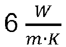
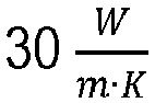
- the coefficient of thermal conductivity of the non-porous monolithic oxide ceramic is advantageously between 1 W m ⁇ K and 50 W m ⁇ K , especially between 2 W m ⁇ K and 40 W m ⁇ K , for example 6 W m ⁇ K for mullite (approx. 70% aluminum oxide) or 30 W m ⁇ K for aluminum oxide with a purity > 99.7%.
- the thermal conductivity coefficient of the layer of fiber composite ceramics is between 0.5 W m ⁇ K and 10 W m ⁇ K preferably between 1 W m ⁇ K and 5 W m ⁇ K . These values apply at 25°C.
- the ratio of the thermal conductivity coefficients of the monolithic ceramic and the fiber composite ceramic in the composite structure is advantageously between 1:1 and 10:1, in particular between 1:1 and 5:1
- the pressure reactor is designed for the following pressure ranges; advantageously 0.1 bar abs -100 bar abs , preferably 1 bar abs -70 bar abs , more preferably 1.5 bar abs -50 bar abs , in particular 5 bar abs -30 bar abs .
- the multi-layer composite pipe according to the invention can have a variable cross-section and a variable wall thickness over its length.
- the multi-layer composite pipe can increase or decrease in a funnel shape in the direction of flow of the gases, with a cross section that narrows in the direction of flow being advantageous for fixed beds and a cross section that becomes wider is advantageous for fluidized beds.
- the edge area of the outer layer can advantageously be sealed at the two ends of the multilayer composite pipe.
- the sealed ends serve as transitions for the gas-tight connection of the composite tube with metal gas-carrying lines, distributors, collectors or bushings through the shell of the surrounding heating chamber.
- Non-porous monolithic oxide ceramics with at least 99% by weight Al 2 O 3 and/or mullite are preferred.
- Haldenwanger Pythagoras 1800Z TM mullite
- the fiber composite materials are characterized by a matrix of ceramic particles between which ceramic fibers, in particular long fibers, are embedded as a wound body or as a textile.
- ceramic fibers in particular long fibers
- the matrix and fiber can consist of all known ceramic materials, with carbon also being treated as a ceramic material in this context.
- Oxidic fiber composite ceramics is understood as meaning a matrix of oxidic ceramic particles which contains ceramic, oxidic and/or non-oxidic fibers.
- Preferred oxides of the fibers and/or the matrix are oxides of an element from the group: Be, Mg, Ca, Sr, Ba, rare earths, Th, U, Ti, Zr, Hf, V, Nb, Ta, Cr, Mo, W, Mn, Fe, Co, Ni, Zn, B, Al, Ga, Si, Ge, Sn, Li, Na, K, Rb, Cs, Re, Ru, Os,lr, Pt, Rh, Pd, Cu, Ag, Au, Cd, in, Tl, Pb, P, As, Sb, Bi, S, Se, Te, and mixtures of these oxides.
- the mixtures are advantageously suitable both as material for the fiber and for the matrix.
- fiber and matrix do not have to be made of the same material.
- the following mixtures are particularly advantageous: binary and ternary mixtures of aluminum oxide, zirconium oxide and yttrium oxide (eg zirconium oxide-reinforced aluminum oxide); mixtures of silicon carbide and aluminum oxide; mixtures of aluminum oxide and magnesium oxide (MgO spinel); mixtures of alumina and silica (mullite); Mixture of aluminum and magnesium silicates, ternary mixture of aluminum oxide, silicon oxide and magnesium oxide (cordierite); steatite (magnesium silicate); zirconia-reinforced alumina; Stabilized zirconium oxide (ZrO 2 ): Stabilizers in the form of magnesium oxide (MgO), calcium oxide (CaO) or yttrium oxide (Y 2 O 3 ), optionally also cerium oxide (CeO 2 ), scandium oxide (SCO 3 ) or ytterbium oxide (YbO 3 ). stabilizers for use; also aluminum titanate (stoichiometric mixture of aluminum oxide and titanium oxide); Silicon
- Al 2 O 3 with 10 to 20 mol % ZrO 2 is advantageously used as zirconium oxide-reinforced aluminum oxide.
- ZrO 2 can advantageously be stabilized with 10 to 20 mol % CaO, preferably 16 mol %, 10 to 20 mol % MgO, preferably 16 mol %, or 5 to 10 mol % Y 2 O 3 , preferably 8 mol % ( "fully stabilized zirconium oxide”) or 1 to 5 mol% Y 2 O 3 , preferably 4 mol% (“partially stabilized zirconium oxide”) can be used.
- 80% Al 2 O 3 , 18.4% ZrO 2 and 1.6% Y 2 O 3 are advantageous as a ternary mixture.
- fibers made of basalt, boron nitride, tungsten carbide, aluminum nitride, titanium dioxide, barium titanate, lead zirconate titanate and/or boron carbide in an oxide-ceramic matrix are also conceivable.
- the fibers of the fiber-reinforced carbon can be arranged radially circumferentially and/or crossing one another on the first layer of the non-porous ceramic.
- Reinforcement fibers come into consideration as fibers, which fall into the classes of oxidic, carbide, nitridic fibers or carbon fibers and SiBCN fibers.
- the fibers of the ceramic composite material are aluminum oxide, mullite, silicon carbide, zirconium oxide and/or carbon fibers.
- Mullite consists of mixed crystals of aluminum oxide and silicon oxide.
- the use of fibers made of oxide ceramics (Al 2 O 3 , SiO 2 , mullite) or of non-oxide ceramics (C, SiC) is preferred.
- Creep-resistant fibers are advantageously used, ie fibers which show no or minimal increase in permanent deformation over time in the creep range - in the temperature range up to 1400°C.
- the 3M company specifies the following limit temperatures for the NEXTEL fibers for the permanent elongation of 1% after 1000 h under a tensile load of 70 MPa: NEXTEL 440: 875 °C, NEXTEL 550 and NEXTEL 610: 1010 °C, NEXTEL 720: 1120 °C on ( Reference: NextelTM Ceramic Textiles Technical Notebook, 3M, 2004 ).
- the fibers advantageously have a diameter of between 10 and 12 ⁇ m. They are advantageous together - usually with a plain or satin weave - woven into textile webs, knitted into tubes or wrapped around a mold as fiber bundles.
- the fiber bundles or fabrics are infiltrated, for example, with a slip that contains the components of the future ceramic matrix, advantageously Al 2 O 3 or mullite ( Schmücker, M. (2007), Fibre-reinforced oxide ceramic materials, materials science and engineering, 38(9), 698-704 ).
- Heat treatment at >700°C finally produces a high-strength composite structure of the ceramic fibers and the ceramic matrix with a tensile strength of advantageously >50 MPa, preferably >70 MPa, more preferably >100 MPa, in particular >120 MPa.
- SiC/Al 2 O 3 SiC/mullite, C/Al 2 O 3 , C/mullite, Al 2 O 3 /Al 2 O 3 , Al 2 O 3 /mullite, mullite/Al 2 O 3 and/or mullite/mullite used.
- the material before the slash designates the fiber type and the material after the slash designates the matrix type.
- Siloxanes, Si precursors and a wide variety of oxides, such as zirconium oxide, can also be used as the matrix system for the ceramic fiber composite structure.
- the ceramic fiber composite material preferably contains at least 99% by weight Al 2 O 3 and/or mullite.
- fiber composite materials based on oxide-ceramic fibers for example 3M TM NEXTEL TM 312, NEXTEL TM 440, NEXTEL TM 550, NEXTEL TM 610 or NEXTEL TM 720.
- the use of NEXTEL 610 and/or NEXTEL 720 is particularly preferred.
- the matrix has a fiber filling level (volume fraction of fibers in the composite structure) of 20 to 40%, the total solids content of the composite structure is between 50 and 80%.
- Fiber composite ceramics based on oxidic ceramic fibers are chemically stable in oxidizing and reducing gas atmospheres (ie no change in weight after storage in air at 1200 °C for 15 hours ( Reference: NextelTM Ceramic Textiles Technical Notebook, 3M, 2004 )) and thermally resistant to over 1300 °C. Fiber composite ceramics have a quasi-ductile deformation behavior. This means that they are resistant to temperature changes and have a quasi-tough fracture behavior. This is how the failure of a component is announced before it breaks.
- the fiber composite material advantageously has a porosity of 20% to 50%; it is therefore not gas-tight as defined in DIN 623-2.
- the fiber composite material advantageously has a long-term use temperature of up to 1500°C, preferably up to 1400°C, particularly preferably up to 1300°C.
- the fiber composite advantageously has a strength of >50 MPa, preferably >70 MPa, particularly preferably >100 MPa, in particular >120 MPa.
- the fiber composite material advantageously has a yield point of elastic deformation of 0.2 to 1%.
- the fiber composite material advantageously exhibits thermal shock resistance in accordance with DIN EN 993-11.
- the fiber composite advantageously has a coefficient of thermal expansion [ppm/K] of 4 to 8.5.
- the fiber composite advantageously has a thermal conductivity of 0.5 to 5 W m ⁇ K on.
- the ceramic fiber composite material can be produced by CVI (Chemical Vapor Infiltration) processes, pyrolysis, in particular LPI (Liquid Polymer Infiltration) processes or by chemical reactions such as LSI (Liquid Silicon Infiltration) processes.
- CVI Chemical Vapor Infiltration
- LPI Liquid Polymer Infiltration
- LSI Liquid Silicon Infiltration
- Sealing both ends or one end of the multi-layer composite pipe can be done in a number of ways: For example, by infiltration or coating of the outer layer of fiber composite ceramics with a polymer, a non-porous ceramic, pyrolytic carbon and/or a metal ( figure 1 a and figure 3 a) sealing can be achieved.
- the sealed areas serve as sealing surfaces.
- This variant can be used up to a temperature range of ⁇ 400 °C.
- the composite pipe is only coated in the edge area of the metallic connecting piece. "Border" means the last section before the
- Transition to another material preferably a metallic material, with a length corresponding to 0.05 to 10 times the inside diameter of the composite pipe, preferably corresponding to 0.1 to 5 times the inside diameter, in particular corresponding to 0.2 to 2 times the inner diameter.
- the thickness of the impregnation advantageously corresponds to the complete layer thickness of the fiber composite ceramics in the edge area. The methods of impregnation are known to those skilled in the art.
- the present invention therefore includes a multi-layer composite pipe with a heat transfer coefficient of> 1000 W / m 2 / K containing at least two layers, an inner layer of non-porous monolithic oxide ceramic, and an outer layer of oxidic fiber composite ceramic, wherein the thickness of the layer of monolithic Oxide ceramic is from 0.5 mm to 45 mm, the total wall thickness of at least two layers is 1 mm to 50 mm, the thickness of the layer of oxidic fiber composite ceramic is less than 90% of the total wall thickness, the inner diameter of the composite pipe 20 mm to 1000 mm, the two layers being non-positively or cohesively connected to one another and forming a component, and "oxide fiber composite ceramics" meaning a matrix of oxide ceramic particles containing ceramic, oxide and/or non-oxide fibers , and wherein the outer layer of the composite pipe im Edge area before the transition to another material, preferably metallic material, is impregnated or coated with polymer, non-porous ceramic, (pyro)carbon and/or metallic material.
- the metal sleeve advantageously contains one or more of the following materials: chromium, titanium, molybdenum, nickel steel 47Ni, alloy 80Pt20Ir, alloy 1.3981, alloy 1.3917 or a trimetal copper/invar/copper.
- the ratio of the length of the lap joint (5) to the inside diameter of the composite pipe is advantageously in the range from 0.05 to 10, preferably from 0.1 to 5, in particular from 0.2 to 2 the outside of the inner layer gas-tightly connected with joining techniques that are known to the person skilled in the art ( Information center for technical ceramics (IZTK): Breviary for technical ceramics, Fahner Verlag, Lauf (2003 )).
- the outer layer is connected to the metal sleeve by a material connection.
- the length of the ceramic overlap ie the area containing the outer layer and metallic sleeve without an inner layer, is advantageously from 0.05 times to 10 times, preferably from 0.1 times to 5 times, in particular from 0. 2x to 2x the inner diameter of the composite pipe.
- the composite pipe of the present invention comprises a metallic gas-carrying line that overlaps in the longitudinal direction of the multi-layer composite pipe, ie in the flow direction of the educts, in some areas with at least one layer of the composite pipe, the inner ceramic layer includes a non-porous monolithic oxide ceramic and at least the outer ceramic layer includes an oxide fiber composite ceramic.
- the ends of the multi-layer composite pipe are advantageously thermostated to a temperature level which is within the limits of the thermal resistance of the impregnation or coating, the gasket, the metal-ceramic bond and the metal sleeve.
- Advantageous ranges are: ⁇ 1000 °C (water glass), ⁇ 500 °C (soldering / mica seal), ⁇ 400 °C (soldering / graphite), ⁇ 300 °C (Kalrez polymer seals), ⁇ 250 °C (silicone rubber, Viton) .
- the constructive solutions and process control concepts suitable for this are known to the person skilled in the art.
- the central area advantageously between 20% and 99% of the total length, preferably between 50% and 99% of the total length, in particular between 90% and 99% of the total length, of the composite pipe is arranged in a heating chamber and can be heated to temperatures of up to 1300 °C or to be heated over it; advantageously 900°C to 1700°C, preferably 1000°C to 1600°C, in particular 1100°C to 1500°C.
- the multi-layer composite pipe is typically arranged vertically, fixed at one end and loose at the other end. It is preferably clamped firmly at the lower end and guided in a displaceable manner in the axial direction at the upper end. In this arrangement, the tube can thermally expand without stress.
- a variant of the solution consists of two concentric tubes ( figure 2 ).
- the inner tube advantageously has an inner tube diameter of 10 mm to 100 mm, preferably 15 mm to 50 mm, in particular 20 mm to 30 mm.
- the inner tube is advantageously open on both sides and the outer tube is advantageously closed on one side.
- the outer tube advantageously has an inner tube diameter of 20 mm to 1000 mm, preferably 50 mm to 800 mm, in particular 100 mm to 500 mm.
- the walls of the inner and outer tubes are advantageously sealed at the open edge area.
- the main reaction section is advantageously located in the annular space between the inner and outer tubes. The reactants can either be introduced into the annular space and the product stream can be drawn off from the inner tube, or vice versa.
- the inlet and outlet connections are located at the open end of the pipe.
- the closed end of the pipe can protrude loosely (without any guide) into the boiler room and expand there unhindered. As a result, no temperature-induced stresses can arise in the axial direction.
- This configuration ensures that the multi-layer composite pipes only have to be clamped and sealed on one side, in the cold, and that thermal expansion can occur unhindered at the closed end.
- Figure 1b, Figure 1c and Figure 1d The options shown to seal the open end are applicable to this variant.
- the present invention thus comprises a double-tube reactor for endothermic reactions, which is characterized in that the reactor comprises two multi-layer composite tubes with a heat transfer coefficient of >1000 W/m 2 /K, each containing at least two layers, an inner layer of non-porous monolithic oxide Ceramic and an outer layer made of oxidic fiber composite ceramics, wherein the thickness of the layer of oxidic fiber composite ceramics is from 0.5 mm to 3 mm, the thickness of the layer of monolithic oxide ceramics is from 0.5 mm to 45 mm, the total wall thickness of at least two Layers is 1 mm to 50 mm, the thickness of the layer of oxidic fiber composite ceramics being less than 90% of the total wall thickness, the inner diameter of the composite pipe being 20 mm to 1000 mm, the two layers being non-positively or materially connected to one another and a component and where "oxide fiber composite ceramics" means a matrix of oxide ceramic particles containing ceramic, oxide and/or non-oxide fibers, and where one composite tube encloses the
- the tightness and temperature resistance of a pipe made of monolithic, non-porous ceramics can be combined with the good-natured failure behavior of fiber-reinforced ceramics ("crack before fracture").
- the device according to the invention with sealed edge areas enables the gas-tight connection of the multilayer composite pipes to the conventionally designed periphery.
- the test piece was a pipe with a monolithic wall made of dense corundum (Friatec product with product number 122-11035-0) with the following dimensions (outside diameter x inside diameter x length): 35mm x 29mm x 64mm.
- the heat transfer coefficient of the tube wall, based on the inside of the wall, was: k loc 9200 (W/m 2 /K).
- the tube was exposed to the flame of a welding torch.
- the welding torch was supplied with acetylene and oxygen and equipped with a welding attachment type Gr3, A, 6-9, S2.5bar.
- the torch tip was aimed perpendicular to the pipe wall at a distance of 50mm. After about 3 seconds the pipe broke. This ended the test. This test confirmed the thermal shock sensitivity of monolithic ceramics.
- the test piece was a pipe with a two-layer wall.
- the wall of the core tube was made of dense monolithic corundum (Friatec product with product number 122-11035-0) with the following dimensions (outer diameter x inner diameter x length): 35mm x 29mm x 64mm.
- the core tube was wrapped with a layer of fiber composite ceramics (ceramic sheet type FW12) with a layer thickness of approx. 1mm.
- the heat transfer coefficient of the tube wall, based on the inside of the wall, was: k loc 3120 (W/m 2 /K).
- the tube was exposed to the flame of a welding torch.
- the welding torch was supplied with acetylene and oxygen and equipped with a welding attachment type Gr3, A, 6-9, S2.5bar.
- the torch tip was aimed perpendicular to the pipe wall at a distance of 50mm.
- a white-hot spot with a length of approx. 25mm (T > 1300°C) formed on the outer wall of the tube.
- the flame was removed from the tube after 20 seconds and returned to the tube 30 seconds later for 20 seconds. The pipe survived this thermal shock undamaged.
Landscapes
- Engineering & Computer Science (AREA)
- Chemical & Material Sciences (AREA)
- Ceramic Engineering (AREA)
- General Engineering & Computer Science (AREA)
- Organic Chemistry (AREA)
- Mechanical Engineering (AREA)
- Materials Engineering (AREA)
- Structural Engineering (AREA)
- Dispersion Chemistry (AREA)
- Health & Medical Sciences (AREA)
- Chemical Kinetics & Catalysis (AREA)
- General Health & Medical Sciences (AREA)
- Inorganic Chemistry (AREA)
- Combustion & Propulsion (AREA)
- Toxicology (AREA)
- Laminated Bodies (AREA)
- Physical Or Chemical Processes And Apparatus (AREA)
- Rigid Pipes And Flexible Pipes (AREA)
- Ceramic Products (AREA)
- Hydrogen, Water And Hydrids (AREA)
Description
- Die vorliegende Erfindung betrifft ein gasdichtes mehrschichtiges Verbundrohr mit einem Wärmedurchgangskoeffizient von > 1000 W/m2/K beinhaltend mindestens zwei Schichten, eine Schicht aus unporöser monolithischer Oxid-Keramik und eine Schicht aus oxidischer Faserverbundkeramik.
- Endotherme Reaktionen stehen häufig am Anfang der Wertschöpfungskette der chemischen Industrie, beispielsweise bei der Spaltung von Erdölfraktionen, der Reformierung von Erdgas oder Naphtha, der Dehydrierung von Propan, der Dehydroaromatisierung von Methan zu Benzol oder der Pyrolyse von Kohlenwasserstoffen. Diese Reaktionen sind stark endotherm, d.h. Temperaturen zwischen 500 °C und 1700 °C sind erforderlich, um technisch und wirtschaftlich interessante Ausbeuten zu erreichen.
- Zum Beispiel enthält der Prozess zur Herstellung von Synthesegas und Wasserstoff aus Erdgas oder Naphtha endotherme Reaktionsschritte, die bei hohen Drücken und Temperaturen durchgeführt werden. Der Standardprozess nach dem Stand der Technik ist die Reformierung von Erdgas mit Wasserdampf (Wasserdampf-reformierung) oder mit Kohlenstoffdioxid (Trocken-reformierung). Dieser Prozess erfordert einen Katalysator, der auf mehrere Reaktionsrohre verteilt ist. Die Reaktionsrohre sind in Öfen installiert und werden durch Brenner befeuert. Die Funktion der Rohrwände ist dabei die Übertragung des Wärmestroms von einer externen Wärmequelle in das Reaktionsvolumen und die hermetische Trennung des Reaktionsvolumens von der umgebenden Wärmequelle unter Erhaltung der Druckdifferenz zwischen den zwei Räumen. Die Rohre der Festbettreaktoren sind typischerweise zylindrisch mit einheitlichem Durchmesser über die gesamte Rohrlänge. Der Werkstoff der Rohre ist typischerweise Edelstahl; in einigen Fällen werden keramische Werkstoffe eingesetzt.
- Technische Reformierungsprozesse werden bei Drücken bis 30 bar und Temperaturen bis 900 °C betrieben, wobei dieser Wert die Produktgastemperatur am Austritt der Reaktionsrohre repräsentiert. Der technische Prozess ist wärmetransport- und gleichgewichtslimitiert. Der Begriff "wärmetransportlimitiert" bedeutet, dass die Reaktionskinetik so schnell wird, dass lokal näherungsweise der Gleichgewichtsumsatz erreicht wird, jedoch kann die Reaktionswärme nicht ausreichend schnell über die Wand der Reaktionsrohre nachgeliefert werden. So stellt sich über die Länge und über den Querschnitt des Reaktionsrohres eine nennenswerte Differenz zur Wandtemperatur ein, die den Umsatz limitiert. Gleichgewichtslimitiert bedeutet, dass der Gleichgewichtsumsatz der Reaktion mit der Temperatur ansteigt. Bei einem Gemisch mit der gängigen Anfangszusammensetzung von H2O:CH4 = 3:1 mol/mol ist bei 900 °C und 30 bar der Gleichgewichtsumsatz auf 86,7 % limitiert. Bei der Verwendung von metallischen Reaktorwerkstoffen ist die Reaktionstemperatur durch die Temperaturbeständigkeit der metallischen Reaktorwerkstoffe und der eingesetzten Katalysatoren auf die genannten 900°C beschränkt.
- Eine höhere Reaktionstemperatur von 1300°C oder höher wäre aus mehreren Gründen wünschenswert, insbesondere um einen höheren Gleichgewichtsumsatz (> 99,9 %) und um eine ausreichend hohe Reaktionsgeschwindigkeit der folgenden unkatalysierten Reaktionen zu erreichen, die für die Synthesegasherstellung relevant sind, beispielsweise:
CH4 + H2O ⇆ CO + 3H2
CH4 + CO2 ⇆ 2CO + 2H2
CH4 ⇆ C + H2
CO2 + H2 ⇆ CO + H2O
CO2 + C ⇆ 2CO.
- Die Produktzusammensetzung ist hauptsächlich vom C:O:H-Verhältnis der Einsatzstoffe bestimmt. Demnach besteht keine Notwendigkeit, die Selektivität einzelner Reaktionen durch einen Katalysator zu erhöhen.
- Diese Temperaturen von > 1300°C erfordern den Einsatz keramischer Werkstoffe, vorzugsweise von Oxidkeramiken. Die Vorteile von keramischen Werkstoffen, insbesondere Oxidkeramiken, sind hohe Temperaturbeständigkeit bis 1800 °C, chemische Passivität, Korrosionsbeständigkeit und hohe Festigkeit. Der größte Nachteil von keramischen Werkstoffen ist deren hohe Sprödigkeit. Diese Eigenschaft wird über die Bruchzähigkeit KIC beschrieben, die beispielsweise gemäß DIN EN ISO 12737 für Metalle, bzw. gemäß DIN EN ISO 15732 für monolithische Keramiken bestimmt wird. Für Stahl, einem Vertreter zäher Werkstoffe, beträgt Klc ≈ 50 MPa √m. Für monolithische Keramiken, beispielsweise Zirkonoxid (ZrO2) oder Korund (Al2O3) beträgt Klc ≅ 3 - 5 MPa √m. Hierdurch sind monolithische Keramiken ungeeignet für Druckapparate mit einem Druck von > 0,5 bar, da diese Werkstoffe das Kriterium "Riss vor Bruch" nicht gewährleisten können, sondern ein plötzlicher, sich nicht ankündigender Bruch stattfinden könnte. Eine Alternative sind Faserverbundkeramiken bestehend aus oxidischen Fasern, die in einer porösen Matrix aus oxidischer Keramik eingebettet sind. Die Porosität von Faserverbundkeramiken kann Werte zwischen 25% und 50% annehmen. Die Vorteile von Faserverbundkeramiken sind hohe Temperaturbeständigkeit bis 1300 °C oder darüber, hohe Temperaturwechselbeständigkeit und ein quasi-duktiles Verformungs- und Bruchverhalten. Die Bruchzähigkeit von Faserverbundkeramiken kann Werte erreichen von Klc ≅ 10 - 50 MPa √m. Als Folge der porösen Struktur besitzen Faserverbundkeramiken eine geringere Dichte, einen niedrigeren Elastizitätsmodul und einen niedrigeren Wärmeleitfähigkeitskoeffizient gegenüber monolithischen Keramiken mit derselben chemischen Zusammensetzung. Die Tabelle 1 enthält eine Liste der relevanten Normen für die Bestimmung dieser Parameter.
Tabelle 1: Liste der relevanten Normen für die Bestimmung struktureller, mechanischer und thermophysikalischer Parameter für monolithische Keramiken und Verbundkeramiken. Parameter Monolithische Keramik Faserverbundkeramik Dichte, Porosität DIN EN 623-2 DIN V ENV 1389 E-Modul DIN V ENV 843-2 DIN EN 658-1 Bruchzähigkeit1 DIN EN ISO 15732 Single-edge-notch-bend2 Temperaturleitfähigkeitskoeffizient DIN EN 821-2 DIN V ENV 1159-2 Spezifische Wärmekapazität DIN EN 821-3 DIN V ENV 1159-3 1: Die Bruchzähigkeit metallischer Werkstoffe wird gemäß DIN EN ISO 12737 bestimmt.
2: M. Kuntz. Risswiderstand keramischer Faserverbundwerkstoffe. Dissertation Universität Karlsruhe, Shaker Verlag, 1996. - Der Wärmeleitfähigkeitskoeffizient ist über die folgende Beziehung definiert:
Wärmeleitfähigkeitskoeffizient = Dichte x (spezifische Wärmekapazität) x Temperaturleitfähigkeitskoeffizient - Beispielhaft enthält die Tabelle 2 einen Vergleich zwischen den Eigenschaften monolithischer Keramiken und Faserverbundkeramiken auf der Basis von Aluminiumoxid.
Tabelle 2: Gegenüberstellung der physikalischen Eigenschaften von monolithischen Keramiken und Verbundkeramiken. Parameter Monolithische Keramik Friatec Degussit® AL23 Faserverbundkeramik WHIPOX® N610/45 Porosität in % 0 26 Dichte in 
3,8 2,9 E-Modul in GPa 380 110 Wärmeleitfähigkeitskoeffizient in 
30 (@100°C) 5,7 (@200°C) 5,5 (@1000°C) 2,7 (@1000°C) - Nachteilig an der porösen Struktur von Faserverbundkeramiken ist ihre Untauglichkeit für die Herstellung von Druckapparaten mit einem Druck von > 0,5 bar. Ferner ist die schlechtere Wärmeleitfähigkeit im Vergleich zur unporösen monolithischen Keramik mit derselben chemischen Zusammensetzung nachteilig, d.h. wenn durch eine Schicht aus diesem Material ein Wärmestrom übertragen werden soll.
-
DE 2821595 A1 offenbart ein hochfestes Keramikverbundrohr, das ein Innenrohr aus Keramikmaterial und wenigstens ein auf das Innenrohr aufgeschrumpftes Außenrohr aus einem Metall- oder Keramikmaterial aufweist. Es findet sich kein Hinweis auf eine Faserverbundkeramik. -
DE 3907087 A1 beschreibt einen Hochdruckbehälter mit einer Wandung aus einem Faserverbundwerkstoff auf einem Innenrohr aus Metall-Keramik-Pulver und einem Außenrohr aus Metall. Es findet sich kein Hinweis auf einen Mehrschichtaufbau mit einem keramischen Innenoder Außenrohr. -
DE 102006038713 A1 offenbart einen druckfesten Körper, wie beispielsweise ein Druckrohr, bestehend aus einem Grundkörper aus Stahl, einer den Grundkörper außenseitig umschließenden ersten Schicht aus keramischem Faserverbundwerkstoff und zumindest einer auf der ersten Schicht angeordneten zweiten Schicht aus faserverstärktem Kunststoff und/oder faserverstärkter Keramik. Die zweite Schicht aus Kunststoff verbietet die Außenbeheizung des Rohres. Ausführungsbeispiele mit rein keramischen Außenrohren werden nicht erwähnt. Es findet sich kein Hinweis auf einen Mehrschichtaufbau mit einem keramischen Innenrohr oder einem Innenrohr aus Faserverbundkeramik. -
DE 102012219870 A1 offenbart ein Verfahren zur Herstellung eines Verbundkörpers aus Stahl und eine den Grundkörper zumindest abschnittsweise außenseitig umschließende Schicht aus einem Faserverbundwerkstoff. Zur Ausbildung des Faserverbundwerkstoffs wird der Grundkörper mit einem Faserwerkstoff vor oder nach dem Umwickeln mit einem Harz imprägniert und erwärmt. Vorteilhaft ist, dass dieses Verfahren in situ durchgeführt werden kann, so dass eine Sanierung maroder Druckleitungen ohne Betriebsunterbrechung möglich ist. Es findet sich kein Hinweis auf einen Mehrschichtaufbau mit einem keramischen Innenrohr oder einem Innenrohr aus Faserverbundkeramik. -
DE 102004049406 A1 beschreibt ein mehrschichtiges Formteil aus mindestens einem langfaserverstärkten Verbundmaterial (1) und mindestens einem kurzfaserverstärkten Verbundmaterial (2), das dadurch gekennzeichnet ist, dass das langfaserverstärkte Verbundmaterial (1) keramische Endlosfasern und keramisches Matrixmaterial enthält, das kurzfaserverstärkte Verbundmaterial (2) keramische Fasern mit einer mittleren Länge in einem Bereich von 1 bis 50 mm und keramisches Matrixmaterial enthält, wobei das langfaserverstärkte Verbundmaterial (1) und das kurzfaserverstärkte Verbundmaterial (2) flächig fest miteinander verbunden sind. Es findet sich kein Hinweis auf eine Kombination einer keramischen Schicht mit einer Faserverbundschicht. -
US 6,733,907 beschreibt einen Verbund aus einer innenliegenden keramischen Trägerstruktur und einer außenliegenden keramischen Wärmedämmschicht. Die Wärmedämmschicht weist eine Dicke von 2 bis 5 mm auf und eine Porosität von > 20 % auf. Die Porosität der Struktur verleiht sowohl monolithischen Keramiken als auch Faserverbundkeramiken eine schlechtere Wärmeleitfähigkeit gegenüber einer unporösen monolithischen Keramik mit derselben chemischen Zusammensetzung. Die keramische Trägerstruktur kann aus Endlosfasern in einer keramischen Matrixstruktur bestehen und weist eine Dicke von 3 bis 10 mm auf. Es wird beschrieben, dass der E-Modul und der Wärmeleitfähigkeitskoeffizient der Wärmedämmschicht jeweils niedriger ist als der entsprechende Wert der keramischen Trägerstruktur. Nachteilig im Sinn der oben formulierten Anforderung an die Funktion der Reaktionsrohre ist hierbei die Untauglichkeit der porösen Verbundstruktur, zwei Räume mit einer nennenswerten Druckdifferenz voneinander zu trennen. Ferner erlaubt die schlechte Wärmeleitung der Verbundstruktur nicht, den erforderlichen Wärmestrom für die endotherme Reaktion ohne Überhitzung der Wand zu übertragen. -
US 2015/078505 beschreibt ein gasdichtes, zweischichtiges Verbundrohr aus Siliciumcarbid zur Endlagerung von nuklearen Kernbrennstoffen beinhaltend eine dichte monolithische SiC-Schicht und eine poröse SiC-SiC-Faserverbundkeramikschicht. Der Vorteil von SiC-Keramiken innerhalb der Familie der Keramiken ist die vergleichsweise hohe Wärmeleitfähigkeit und die hohe Temperaturwechselbeständigkeit. Der Nachteil von SiC-Keramiken ist die vergleichsweise geringe chemische Beständigkeit im Bezug auf oxidierende oder aufkohlende Atmosphären. Die thermodynamische Analyse von Eckel et al (NASA Technical Memorandum, Wyoming, September 12-16, 1989) und Hallum et al. (NASA Technical Memorandum, Chicago, Illinois, April 27-May 1, 1986) zeigen, dass im technisch relevanten Bereich von 0,1% bis 1% Volumenanteile für Methan, CO und/oder Wasserdampf Oxidations- Reduktionszyklen stattfinden können, so dass die SiC-Keramik korrodiert. Figur 4 von Hallum et al. zeigt den Einfluss der Temperatur bei dem Sinterungsprozess von SiC-Keramiken; ab einer Temperatur von 1100°C wird die Korrosion so stark, dass sich einzelne Kristalle aus der Oberfläche lösen. Diese Korrosion wird ferner verstärkt durch eine wechselnde Atmosphäre zwischen reduzierend und oxidierend. Folglich werden SiC-Keramiken als Reaktor-Materialien für endotherme Reaktionen in oxidierenden sowie zwischen reduzierend und oxidierend periodisch wechselnden Reaktionsatmosphären nicht in Betracht gezogen. -
US 5,881,775 beschreibt ein zwei-schichtiges Verbundrohr mit einer inneren Schicht aus unporösem monolithischen Keramikmaterial, das Oxidmaterial wie Mullit oder Aluminiumoxid enthält, und einer äußeren Verstärkungsschicht aus Faserverbundkeramik beinhaltend Oxidmaterial, z.B. Mullit oder Aluminiumoxid. Eine allgemeine Wanddicke der beiden Schichten wird inUS 5,881,775 nicht offenbart. Im Beispiel vonUS 5,881,775 ist ein zweischichtiges Rohr mit einem inneren Rohr aus Aluminiumoxid mit 10 cm Außendurchmesser und 0,64 cm Wandstärke beschrieben. -
US 2012/0003128 beschreibt ein Verbindungsstück zwischen einem Rohr aus unporöser monolithischer Keramik und metallischen Zuleitungen. Das keramische Rohr weist eine Porosität von < 5% auf.US 2012/0003128 basiert auf einer kraftschlüssigen Verbindung zwischen dem Keramikrohr und dem metallischen Anschlussteil, der den Endabschnitt des Keramikrohres umgibt. Der Kraftschluss wird über zwei konzentrisch angeordnete Metallringe gewährleistet, wobei der innere Ring Teil der Anschlussleitung ist. Der äußere Schrumpfring hat eine geringere thermische Ausdehnung als der innere Ring; dadurch soll die Tendenz des inneren Schrumpfringes unterdrückt werden, sich bei Erwärmung vom keramischen Rohr zu lösen. Nachteilig an dieser Lösung ist, dass, bedingt durch die Wahl metallischer Schrumpfringe, die radiale Anpresskraft zwischen dem Keramikrohr und dem inneren Schrumpfring mit der Temperatur variiert. Im schlimmsten Fall kann die Dichtigkeit der Verbindung beeinträchtigt oder das Keramikrohr beschädigt werden. Ferner bleibt inUS 2012/0003128 der größte Abschnitt des keramischen Rohres, der nicht von den Schrumpfringen umgeben wird, ungeschützt, d.h. das Problem der Sprödigkeit dieses Materials bleibt ungelöst. - Ein Rohr beinhaltend mindestens zwei Schichten, eine Schicht aus unporöser monolithischer Oxid-Keramik und eine Schicht aus oxidischer Faserverbundkeramik ist nicht mit einer keramischen Hohlfasern gemäß
JP 2003053166 US4222977 undUS5707584 beschreiben die Herstellung keramischer Hohlfasermembranen. Die Rohrwand kann eine Wandstärke zwischen 30µm und 500µm aufweisen und ist monolithisch, d.h. ihre mechanischen Eigenschaften sind identisch zu den Eigenschaften gewöhnlicher monolithischer Keramiken. Das bedeutet, dass keramische Hohlfasern starr und spröde und damit ungeeignet sind, um ein quasi-duktiles Verformungsverhalten wie bei Faserverbundkeramiken zu erzielen. Durch die inJP 2003053166 - Demnach werden im Stand der Technik bislang keine Materialien offenbart, die für die Herstellung von Reaktionsrohren, einsetzbar bei Betriebsdrücken von 1 bis 50 bar, Reaktionstemperaturen bis 1400°C und von einer äußeren Wärmequelle - üblicherweise einer Heizkammer - beheizbar, geeignet wären.
- Die Lösungen, die auf der Kombination einer Armierung aus Faserverbundkeramik und metallischen Rohren aufbauen, sind ungeeignet, um die thermischen und chemischen Einschränkungen der metallischen Werkstoffe, d.h. maximale Reaktionstemperatur bis ca. 950°C und korrosionsanfällig bei wechselnd oxidierenden/reduzierender Atmosphäre, zu überwinden. Die Lösungen, die auf der schichtweisen Kombination einer Armierung aus Faserverbundkeramik und keramischen Formkörpern aufbauen, enthalten keine Lehren (i) zum effektiven Wärmetransport durch die Schichten und (ii) zur chemischen Resistenz und (iii) zur hermetischen Abgrenzung des Reaktionsvolumens von der umgebenden Heizkammer bei einer Druckdifferenz bis 50 bar. Insbesondere sind hermetisch dichte Übergänge zwischen den Rohrenden und metallischen Leitungen für die Einleitung der Reaktanden und für die Ableitung der Produktströme in die bzw. aus den Reaktionsrohren ungeklärt.
- Die Abgrenzung des Reaktionsvolumens von der umgebenden Heizkammer wird im Stand der Technik in Abhängigkeit von der benötigten Temperatur auf nachfolgende Arten gelöst. Bei Temperaturen in einem Bereich bis < 300°C werden typischerweise Polymere als Dichtungselemente eingesetzt. Ferner besteht die Möglichkeit der Imprägnierung mit Polymeren. Bei Temperaturen bis < 400°C werden metallische Hülsen verwendet, die stoffschlüssig unter Verwendung von Löt- oder Klebemittel angebracht werden. Bei Temperaturen bis < 1000°C werden die metallischen Hülsen formschlüssig aufgeschrumpft (z.B.
DE 1995105401 ). Die besagten Metallhülsen müssen für diesen Verwendungszweck dünnwandig im Bereich von 0,3 bis 1 mm sein. Mit solchen Metallhülsen könnten bei hohen Temperaturen oberhalb 800 °C nur Druckdifferenzen von max. 3 bar erreicht werden, da das Metall ansonsten anfängt zu fließen. - Die Aufgabe der vorliegenden Erfindung war demnach die Bereitstellung eines geeigneten Werkstoffes für Reaktionsrohre, die folgendes Eigenschaftsprofil aufweisen: (i) wärmedurchlässig mit einem Wärmedurchgangskoeffizient > 1000 W/m2/K
- (ii) temperaturbeständig bis ca. 1400°C,
- (iii) druckbeständig bis ca. 50 bar bzw. beständig bei Druckdifferenzen bis ca. 100 bar, (iv) korrosionsbeständig gegen reduzierende und gegen oxidierende Atmosphäre mit einem Sauerstoffpartialdruck von 10-25 bar bis 10 bar und (v) temperaturwechselbeständig gemäß DIN EN 993-11.
- Ferner war Aufgabe der vorliegenden Erfindung, eine Verbindungseinheit / ein Verbindungsstück zwischen dem Werkstoff, d.h. dem Reaktorrohr, einerseits und den metallischen gasführenden Leitungen für die Produkte und Edukte andererseits aufzuzeigen, die ebenso (i) temperaturbeständig bis oberhalb 1100°C, (ii) druckbeständig bis 40 bar, (iii) korrosionsbeständig gegen oxidierende und gegen reduzierende Atmosphäre und (iv) temperaturwechselbeständig ist. Gelöst wurde die Aufgabe mit einem mehrschichtigen Verbundrohr mit einem Wärmedurchgangskoeffizient von > 1000 W/m2/K beinhaltend mindestens zwei Schichten, eine innere Schicht aus unporöser monolithischer Oxid-Keramik und eine äußere Schicht aus oxidischer Faserverbundkeramik, wobei die Dicke der Schicht aus oxidischer Faserverbundkeramik von 0,5 mm bis 3 mm beträgt, wobei die Dicke der Schicht aus monolithischer Oxid-Keramik von 0,5 mm bis 45 mm beträgt, wobei die gesamte Wandstärke aus mindestens zwei Schichten 1 mm bis 50 mm beträgt, wobei die Dicke der Schicht aus oxidischer Faserverbundkeramik weniger als 90 % der gesamten Wandstärke beträgt, wobei der Rohrinnendurchmesser des Verbundrohres 20 mm bis 1000 mm beträgt, wobei die zwei Schichten kraftschlüssig oder stoffschlüssig miteinander verbunden sind und ein Bauteil bilden und wobei unter "oxidischer Faserverbundkeramik" eine Matrix aus oxidischen keramischen Partikeln verstanden wird, die keramische, oxidische und/oder nicht-oxidische Fasern, enthält.
- Die zwei Schichten haften aneinander durch kraftschlüssige oder stoffschlüssige Verbindungen. Relevante kraftschlüssige Verbindungen sind beispielsweise Schraubverbindungen oder Pressverbindungen. Relevante stoffschlüssige Verbindungen für diese Erfindung sind Löten, Kleben, Sintern. Alle Verbindungsarten gehören zum Stand der Technik (W. Tochtermann, F. Bodenstein: Konstruktionselemente des Maschinenbaues, Teil 1. Grundlagen; Verbindungselemente; Gehäuse, Behälter, Rohrleitungen und Absperrvorrichtungen. Springer-Verlag, 1979).
- Die Wand des mehrschichtigen Verbundrohrs beinhaltet zumindest bereichsweise zwei Schichten, eine Schicht aus unporöser monolithischer Oxid-Keramik und eine Schicht aus oxidischer Faserverbundkeramik; d.h. es kann sich bei dem mehrschichtigen Verbundrohr auch um einen Verbundrohr-Abschnitt handeln. Beispielsweise sei ein zoniertes oder punktuelles nur bereichsweise aus zwei Schichten bestehendes Verbundrohr genannt. Bevorzugt beinhaltet jedoch die gesamte Wand des Verbundrohres, die einer äußeren Temperatur, z.B. durch eine Heizkammer, von > 1100°C ausgesetzt ist, mindestens zwei Schichten, eine Schicht aus unporöser monolithischer Oxid-Keramik und eine Schicht aus oxidischer Faserverhundkeramik.
- Das mehrschichtige Verbundrohr weist in dem Rohrabschnitt, der einer äußeren Temperatur, z.B. durch eine Heizkammer, von > 1100°C ausgesetzt ist, vorteilhaft keine metallischen Schichten auf.
- Vorteilhaft ist das Innenrohr umwickelt mit einer Schicht aus oxidischer Faserverbundkeramik. Die zwei Schichten können kraftschlüssig oder stoffschlüssig miteinander verbunden und ein Bauteil bilden. Die Eigenschaften dieses Bauteils sind durch die Temperaturbeständigkeit und das Verformungsverhalten der Schicht aus oxidischer Faserverbundkeramik bestimmt. Die Dichtigkeit ist durch das Innenrohr aus Oxid-Keramik gegeben. Bei Verwendung eines oxid-keramischen Innenrohrs weist die Innenseite der Rohrwand eine hohe chemische Beständigkeit und Abriebfestigkeit, mit einer Härte > 14000 MPa für Aluminiumoxid, > 12000 MPa für Zirkonoxid, auf.
- Bei 1400°C sind beispielsweise Aluminiumoxid und Magnesiumoxid über den gesamten Bereich von einem Sauerstoffpartialdruck von 10-25 bar bis 10 bar beständig, während alle anderen keramischen Werkstoffe einen Übergang zwischen Reduktion und Oxidation durchlaufen und dadurch korrodieren (Darken, L. S., & Gurry, R. W. (1953). Physicalchemistry of metals. McGraw-Hill).
- Der Rohrinnendurchmesser des mehrschichtigen Verbundrohres beträgt 20 mm bis 1000 mm, bevorzugt 50 mm bis 800 mm, insbesondere 100 mm bis 500 mm. Die gesamte Wandstärke aus mindestens zwei Schichten beträgt 1 mm bis 50 mm, bevorzugt 1 mm bis 30 mm, insbesondere 2 mm bis 20 mm. Dabei beträgt die Dicke der Schicht aus oxidischer Faserverbundkeramik weniger als 90 %, bevorzugt weniger als 50 %, insbesondere weniger als 25 % der gesamten Wandstärke; vorteilhaft beträgt die Dicke der Schicht aus oxidischer Faserverbundkeramik mindestens 10 % der gesamten Wandstärke. Die Dicke der Schicht aus monolithischer Oxid-Keramik beträgt von 0,5 mm bis 45 mm, bevorzugt von 1 mm bis 25 mm, besonders bevorzugt von 3 mm bis 15 mm. Die Dicke der Schicht aus oxidischer Faserverbundkeramik beträgt von 0,5 mm bis 3 mm.
- Die Länge des mehrschichtigen Verbundrohres beträgt vorteilhaft 0,5 bis 20 m, bevorzugt 1 bis 10 m, insbesondere 1,5 bis 7 m.
- Das erfindungsgemäße mehrschichtige Verbundrohr weist vorteilhaft eine offene Porösität von ε < 5 %, bevorzugt ε < 4 %, besonders bevorzugt ε < 3 %, ferner bevorzugt ε < 2 %, insbesondere ε < 1 %, auf. Das mehrschichtige Verbundrohr ist besonders vorteilhaft gasdicht. Unter dem Begriff "gasdicht" wird ein Festkörper verstanden, der gemäß DIN EN 623-2 eine offene Porosität von Null besitzt. Die zulässige Messungenauigkeit liegt bei < 0,3 %.
- Die Dichte der unporösen monolithischen Oxid-Keramik ist vorteilhaft größer als die Dichte der oxidischen Faserverbundkeramik. Die Dichte der unporösen monolithischen Oxid-Keramik beträgt vorteilhaft zwischen 1000


- Das materialabhängige Elastizitätsmodul der unporösen monolithischen Oxid-Keramik ist vorteilhaft größer als das Elastizitätsmodul der oxidischen Faserverbundkeramik. Das Elastizitätsmodul der unporösen monolithischen Oxid-Keramik beträgt vorteilhaft zwischen 100 GPa und 500 GPa, insbesondere zwischen 150 GPa und 400 GPa, beispielsweise 150 GPa für Mullit (ca. 70% Aluminiumoxid) oder 380 GPa für Aluminiumoxid mit einer Reinheit > 99,7%. Das Elastizitätsmodul der Schicht aus Faserverbundkeramik beträgt zwischen 40 GPa und 200 GPa. Diese Werte gelten bei 25°C. Das Verhältnis der Elastizitätsmoduln der monolithischen Keramik und der Faserverbundkeramik in der Verbundstruktur beträgt vorteilhaft zwischen 1:1 und 5:1, insbesondere zwischen 1:1 und 3:1.
- Der materialabhängige Wärmeleitfähigkeitskoeffizient der unporösen monolithischen Oxid-Keramik ist vorteilhaft größer als der Wärmeleitfähigkeitskoeffizient der oxidischen Faserverbundkeramik. Der Wärmeleitfähigkeitskoeffizient der unporösen monolithischen Oxid-Keramik beträgt vorteilhaft zwischen




- Der Druckreaktor ist für folgende Druckbereiche ausgelegt; vorteilhaft 0,1 barabs - 100 barabs, bevorzugt 1 barabs - 70 barabs, weiter bevorzugt 1,5 barabs - 50 barabs, insbesondere 5 barabs - 30 barabs.
- Die Druckdifferenz zwischen der Reaktionskammer und der Heizkammer beträgt vorteilhaft von 0 bar bis 100 bar, bevorzugt von 0 bar und 70 bar, weiter bevorzugt von 0 bar bis 50 bar, insbesondere von 0 bar bis 30 bar (Kapitel Cb: Wärmedurchgang, VDI-Wärmeatlas, 8. Auflage, 1997). Gemäß dieser Definition gilt:

- Dabei bedeuten die Symbole:
- Rw : Wärmedurchgangswiderstand einer mehrschichtigen zylindrischen Wand in

- kloc : Wärmedurchgangskoeffizient einer mehrschichtigen zylindrischen Wand in

- A: Zylindrische Mantelfläche in m 2,
- λ: Wärmeleitfähigkeitskoeffizient einer homogenen Schicht in

- δ: Dicke einer homogenen Schicht in m,
- n: Anzahl der Schichten einer mehrschichtigen zylindrischen Wand,
- die Indizes:
- 1: Innenseite einer zylindrischen Schicht,
- 2: Außenseite einer zylindrischen Schicht,
- m: Mittlere Fläche
- Das erfindungsgemäße mehrschichtige Verbundrohr kann über seine Länge einen variablen Querschnitt und eine variable Wandstärke haben. Beispielsweise kann das mehrschichtige Verbundrohr in Strömungsrichtung der Gase trichterförmig zu- oder abnehmen, wobei ein in Strömungsrichtung enger werdenden Querschnitt vorteilhaft für Festbetten ist und ein weiter-werdenden Querschnitt vorteilhalft für Wirbelschichten.
- An den zwei Enden des mehrschichtigen Verbundrohres kann der Randbereich der äußeren Schicht vorteilhaft versiegelt sein. Die versiegelten Enden dienen als Übergänge zur gasdichten Verbindung des Verbundrohres mit metallischen gasführenden Leitungen, Verteilern, Sammlern oder Durchführungen durch die Hülle der umgebenden Heizkammer.
- Als unporöse monolithische Oxid-Keramik können alle dem Fachmann bekannten oxidischen Keramiken verwendet werden, insbesondere analog dem Informationszentrum Technische Keramik (IZTK): Brevier technische Keramik. Fahner Verlag, Lauf (2003). Bevorzugt sind unporöse monolithische Oxid-Keramiken mit mindestens 99 Gew-% Al2O3 und/oder Mullit. Als unporöse Keramik können insbesondere Haldenwanger Pythagoras 1800Z™ (Mullit), Alsint 99,7™ oder Friatec Degussit® AL23 (Aluminiumoxid) zum Einsatz kommen.
- Die Faserverbundwerkstoffe sind charakterisiert durch eine Matrix aus keramischen Partikeln zwischen den keramischen Fasern, insbesondere Langfasern, als Wickelkörper oder als Textil eingebettet sind. Es wird von faserverstärkter Keramik, Verbundkeramik oder auch Faserkeramik gesprochen. Matrix und Faser können dabei im Prinzip aus allen bekannten keramischen Werkstoffen bestehen, wobei in diesem Zusammenhang auch Kohlenstoff als keramischer Werkstoff behandelt wird.
- Unter "oxidischer Faserverbundkeramik" wird eine Matrix aus oxidischen keramischen Partikeln verstanden, die keramische, oxidische und/oder nicht-oxidische Fasern, enthält.
- Bevorzugte Oxide der Fasern und/oder der Matrix sind Oxide eines Elementes aus der Gruppe: Be, Mg, Ca, Sr, Ba, Seltene Erden, Th, U, Ti, Zr, Hf, V, Nb, Ta, Cr, Mo, W, Mn, Fe, Co, Ni, Zn, B, Al, Ga, Si, Ge, Sn, Li, Na, K, Rb, Cs, Re, Ru, Os,lr, Pt, Rh, Pd, Cu, Ag, Au, Cd, in, Tl, Pb, P, As, Sb, Bi, S, Se, Te, sowie Mischungen dieser Oxide.
- Die Mischungen sind sowohl als Material für die Faser als auch für die Matrix vorteilhaft geeignet. Faser und Matrix müssen generell nicht aus demselben Material sein.
- Grundsätzlich sind nicht nur binäre, sondern auch tertiäre und höhere Mischungen geeignet und von Bedeutung. In einer Mischung können die einzelnen Bestandteile in gleicher molarer Menge vorkommen, vorteilhaft sind aber Mischungen mit stark unterschiedlicher Konzentration der einzelnen Bestandteile der Mischung, bis hin zu Dotierungen, bei denen eine Komponente in Konzentrationen von < 1 % vorkommt.
- Besonders vorteilhaft sind folgende Mischungen: Binäre und ternäre Mischungen aus Aluminiumoxid, Zirkoniumoxid und Yttriumoxid (z.B. Zirkoniumoxidverstärktes Aluminiumoxid); Mischungen aus Siliziumcarbid und Aluminiumoxid; Mischungen aus Aluminiumoxid und Magnesiumoxid (MgO-Spinell); Mischungen aus Aluminiumoxid und Siliziumoxid (Mullit); Mischung aus Aluminium- und Magnesiumsilikate, Ternäre Mischung aus Aluminiumoxid, Siliziumoxid und Magnesiumoxid (Cordierit); Steatit (Magnesiumsilikat); Zrikonoxid-verstärktes Aluminiumoxid; Stabilisiertes Zirkoniumoxid (ZrO2): Stabilisatoren in Form von Magnesiumoxid (MgO), Calciumoxid (CaO) oder Yttriumoxid (Y2O3), gegebenenfalls kommen auch Ceroxid (CeO2), Scandiumoxid (SCO3) oder Ytterbiumoxid (YbO3) als Stabilisatoren zum Einsatz; ferner Aluminiumtitanat (stöchiometrische Mischung von Aluminiumoxid und Titanoxid); Siliziumnitrid und Aluminiumoxid (Siliziumaluminiumoxinitride SIALON).
- Als zirkoniumoxidverstärktes Aluminiumoxid wird vorteilhaft Al2O3 mit 10 bis 20 Mol-% ZrO2 eingesetzt. Zur Stabilisierung von ZrO2 kann vorteilhaft 10 bis 20 Mol-% CaO, bevorzugt 16 Mol-%, 10 bis 20 Mol-% MgO, bevorzugt 16, oder 5 bis 10 Mol-% Y2O3, bevorzugt 8 Mol-% ("vollstabilisiertes Zirkonoxid") oder 1 bis 5 Mol-% Y2O3, bevorzugt 4 Mol-% ("teilstabilisiertes Zirkonoxid") verwendet werden. Als ternäre Mischung sind z.B. 80% Al2O3, 18,4% ZrO2 und 1,6% Y2O3 vorteilhaft.
- Neben den genannten Materialien (Mischungen und Einzelbestandteile) sind auch Fasern aus Basalt, Bornitrid, Wolframcarbid, Aluminiumnitrid, Titandioxid, Bariumtitanat, Bleizirkonattitanat und/oder Borcarbid in oxid-keramischer Matrix denkbar.
- Um eine gewünschte Armierung durch die zumindest zwei Schichten zu erzielen, können die Fasern des faserverstärkten Kohlenstoffs radial umlaufend und/oder sich kreuzend auf der ersten Schicht der unporösen Keramik angeordnet sein.
- Als Fasern kommen Verstärkungsfasern in Frage, die in die Klassen oxidische, carbidische, nitridische Fasern bzw. C-Fasern und SiBCN-Fasern fallen. Insbesondere ist vorgesehen, dass die Fasern des keramischen Verbundwerkstoffes Aluminiumoxid-, Mullit-, Siliziumcarbid-, Zirkonoxid- und/oder Kohlenstoff-Fasern sind. Mullit besteht dabei aus Mischkristallen aus Aluminiumoxid und Siliziumoxid. Bevorzugt ist die Verwendung von Fasern aus Oxidkeramik (Al2O3, SiO2, Mullit) oder aus Nichtoxidkeramik (C, SiC).
- Es kommen vorteilhaft kriechbeständige Fasern zum Einsatz, d. h. Fasern, die im Kriechbereich - im Temperaturbereich bis 1400 °C - keine oder minimale zeitliche Zunahme der bleibenden Verformung, also der Kriechdehnung zeigen. Die Firma 3M gibt für die NEXTEL-Fasern folgende Grenztemperaturen an für die bleibende Dehnung von 1 % nach 1000 h unter Zugbelastung von 70 MPa an: NEXTEL 440: 875 °C, NEXTEL 550 und NEXTEL 610: 1010 °C, NEXTEL 720: 1120 °C an (Referenz: Nextel™ Ceramic Textiles Technical Notebook, 3M, 2004).
- Die Fasern haben vorteilhaft einen Durchmesser zwischen 10 und 12 µm. Sie sind vorteilhaft miteinander - üblicherweise mit Leinwand- oder Satinbindung - zu Textilbahnen verwoben, zu Schläuchen gestrickt oder als Faserbündel um eine Form gewickelt. Zur Herstellung des keramischen Verbundsystems werden die Faserbündel oder -gewebe beispielsweise mit einem Schlicker, der die Komponenten der späteren keramischen Matrix, vorteilhaft Al2O3 oder Mullit, enthält, infiltriert (Schmücker, M. (2007), Faserverstärkte oxidkeramische Werkstoffe, Materialwissenschaft und Werkstofftechnik, 38(9), 698-704). Durch Wärmebehandlung bei > 700 °C entsteht schließlich eine hochfeste Verbundstruktur aus den Keramikfasern und der keramischen Matrix mit einer Zugfestigkeit von vorteilhaft > 50 MPa, bevorzugt > 70 MPa, weiter bevorzugt > 100MPa, insbesondere > 120MPa.
- Bevorzugter Weise wird als keramischer Faserverbundwerkstoff SiC/ Al2O3, SiC/Mullit, C/ Al2O3, C/Mullit, Al2O3/Al2O3, Al2O3/Mullit, Mullit/ Al2O3 und/oder Mullit/Mullit eingesetzt. Dabei bezeichnet das Material vor dem Schrägstrich den Fasertyp und das Material nach dem Schrägstrich den Matrixtyp. Als Matrixsystem für die keramische Faserverbundstruktur können auch Siloxane, Si- Precursoren und unterschiedlichste Oxide, wie zum Beispiel auch Zirkonoxid, eingesetzt werden. Bevorzugt enthält der keramische Faserverbundwerkstoff mindestens 99 Gew-% Al2O3 und/oder Mullit.
- In der vorliegenden Erfindung werden bevorzugt Faserverbundwerkstoffe auf der Basis oxidkeramischer Fasern, beispielsweise 3M™ NEXTEL™ 312, NEXTEL™ 440, NEXTEL™ 550, NEXTEL™ 610 oder NEXTEL™ 720 eingesetzt. Besonders bevorzugt ist die Verwendung von NEXTEL 610 und / oder NEXTEL 720.
- Die Matrix weist einen Füllgrad an Fasern (Volumenanteil der Fasern in der Verbundstruktur) von 20 bis 40 % auf, der gesamte Feststoffgehalt der Verbundstruktur beträgt zwischen 50 und 80 %. Faserverbundkeramiken auf Basis oxidischer keramischer Fasern sind chemisch beständig in oxidierender und in reduzierender Gasatmosphäre (d. h. keine Gewichtsänderung nach Lagerung in Luft bei 1200 °C über 15h (Referenz: Nextel™ Ceramic Textiles Technical Notebook, 3M, 2004)) und thermisch beständig bis über 1300 °C. Faserverbundkeramiken besitzen ein quasi duktiles Verformungsverhalten. Damit sind sie temperaturwechselbeständig und besitzen ein quasi zähes Bruchverhalten. So kündigt sich das Versagen eines Bauteils an, bevor es bricht.
- Der Faserverbundwerkstoff weist vorteilhaft eine Porosität von 20 % bis 50 % auf; sie ist demnach nicht gasdicht gemäß Definition in DIN 623-2.
- Der Faserverbundwerkstoff weist vorteilhaft eine Langeinsatztemperatur von bis zu 1500 °C, bevorzugt bis zu 1400 °C, besonders bevorzugt bis zu 1300 °C auf.
- Der Faserverbundwerkstoff weist vorteilhaft eine Festigkeit > 50 MPa, bevorzugt > 70 MPa, besonders bevorzugt > 100 MPa, insbesondere > 120 MPa auf.
- Der Faserverbundwerkstoff weist vorteilhaft eine Streckgrenze elastischer Verformung von 0,2 bis 1 % auf.
- Der Faserverbundwerkstoff weist vorteilhaft eine Temperaturwechselbeständigkeit gemäß DIN EN 993-11 auf.
- Der Faserverbundwerkstoff weist vorteilhaft einen thermischen Wärmeausdehnungskoeffizient [ppm/K] von 4 bis 8,5 auf.
- Der Faserverbundwerkstoff weist vorteilhaft eine thermische Leitfähigkeit von 0,5 bis 5

- Der keramische Faserverbundwerkstoff kann durch CVI (Chemical Vapour Infiltration) - Verfahren, Pyrolyse, insbesondere LPI (Liquid Polymer Infiltration) -Verfahren oder durch chemische Reaktion wie LSI (Liquid Silicon Infiltration) -Verfahren hergestellt werden.
- Die Versiegelung beider Enden oder eines Endes des mehrschichtigen Verbundrohres kann auf vielfache Art und Weise durchgeführt werden:
Beispielsweise kann durch Infiltration oder Beschichtung der äußeren Schicht aus Faserverbundkeramik mit einem Polymer, einer unporösen Keramik, Pyrokohlenstoff und/oder einem Metall (Figur 1 a undFigur 3 a) eine Versiegelung erreicht werden. Die versiegelten Bereiche dienen als Dichtflächen. Diese Variante kann bis zu einem Temperaturbereich von < 400 °C eingesetzt werden. Vorteilhaft wird das Verbundrohr lediglich im Randbereich zu dem metallischen Verbindungsstück beschichtet. "Randbereich" bedeutet der letzte Abschnitt vor dem - Übergang zu einem anderen Werkstoff, bevorzugt zu einem metallischen Werkstoff, mit einer Länge entsprechend dem 0,05- bis 10-fachem Innendurchmesser des Verbundrohres, bevorzugt entsprechend dem 0,1- bis 5-fachem Innendurchmesser, insbesondere entsprechend dem 0,2- bis 2-fachem Innendurchmesser. Die Dicke der Imprägnierung entspricht vorteilhaft der kompletten Schichtdicke der Faserverbundkeramik im Randbereich. Die Verfahren zur Imprägnierung sind dem Fachmann bekannt.
- Die vorliegende Erfindung umfasst demnach ein mehrschichtiges Verbundrohr mit einem Wärmedurchgangskoeffizienten von > 1000 W/m2/K beinhaltend mindestens zwei Schichten, eine innere Schicht aus unporöser monolithischer Oxid-Keramik, und eine äußere Schicht aus oxidischer Faserverbundkeramik, wobei die Dicke der Schicht aus monolithischer Oxid-Keramik von 0,5 mm bis 45 mm beträgt, wobei die gesamte Wandstärke aus mindestens zwei Schichten 1 mm bis 50 mm beträgt, wobei die Dicke der Schicht aus oxidischer Faserverbundkeramik weniger als 90 % der gesamten Wandstärke beträgt, wobei der Rohrinnendurchmesser des Verbundrohres 20 mm bis 1000 mm beträgt, wobei die zwei Schichten kraftschlüssig oder stoffschlüssig miteinander verbunden sind und ein Bauteil bilden und wobei unter "oxidischer Faserverbundkeramik" eine Matrix aus oxidischen keramischen Partikeln verstanden wird, die keramische, oxidische und/oder nicht-oxidische Fasern, enthält, und wobei die äußere Schicht des Verbundrohres im Randbereich vor dem Übergang zu einem anderen Werkstoff, bevorzugt metallischen Werkstoff, mit Polymer, unporöser Keramik, (Pyro-)Kohlenstoff und/oder metallischem Werkstoff imprägniert oder beschichtet ist.
- Eine andere Möglichkeit der Versiegelung besteht vorteilhaft in dem Anbringen einer Hülse aus Metall an den Randbereich des mehrschichtigen Verbundrohres, die bereichsweise mit Hilfe eines Überlappstoßes (5), wie in der
Figur 1b ersichtlich, zwischen der inneren und der äußeren Schicht angeordnet ist (Figur 1b ). Vorteilhaft enthält die Hülse aus Metall einen oder mehrere der folgenden Werkstoffe: Chrom, Titan, Molybdän, Nickelstahl 47Ni, Legierung 80Pt20Ir, Legierung 1.3981, Legierung 1.3917 oder ein Trimetall Kupfer / Invar / Kupfer. Vorteilhaft liegt das Verhältnis der Länge des Überlappstoßes (5) zu dem Innendurchmesser des Verbundrohres im Bereich von 0,05 bis 10, bevorzugt von 0,1 bis 5, insbesondere von 0,2 bis 2. In diesem Bereich ist die Hülse aus Metall mit der Außenseite der inneren Schicht gasdicht verbunden mit Fügetechniken, die dem Fachmann bekannt sind (Informationszentrum Technische Keramik (IZTK): Brevier technische Keramik, Fahner Verlag, Lauf (2003)). Die äußere Schicht ist durch eine stoffschlüssige Verbindung mit der Hülse aus Metall verbunden. Vorteilhaft beträgt die Länge des keramischen Überlappes, d.h. der Bereich beinhaltend äußere Schicht und metallische Hülse ohne innere Schicht, vom 0,05-fachen bis zum 10-fachen, bevorzugt von 0,1-fachen bis zum 5-fachen, insbesondere von 0,2-fachen bis zum 2-fachen des Innendurchmessers des Verbundrohres. - Das Verbundrohr der vorliegenden Erfindung umfasst eine metallische gasführende Leitung, die in Längsrichtung des mehrschichtigen Verbundrohres, d.h. in Strömungsrichtung der Edukte, bereichsweise mit mindestens einer Schichten des Verbundrohres überlappt, wobei die innere keramische Schicht eine unporöse monolithische Oxid-Keramik beinhaltet und zumindest die äußere keramische Schicht eine oxidische Faserverbundkeramik beinhaltet.
- Die Enden des mehrschichtigen Verbundrohres sind vorteilhaft auf ein Temperaturniveau thermostatisiert, das innerhalb der Grenzen der thermischen Beständigkeit der Imprägnierung oder Beschichtung, der Dichtung, der Metall-Keramik-Verbindung und der Metallhülse liegt. Vorteilhafte Bereiche sind: < 1000 °C (Wassserglas), < 500 °C (Löten / Glimmerdichtung), < 400 °C (Löten / Graphit), < 300 °C (Polymerdichtungen Kalrez), < 250 °C (Silikongummi, Viton). Die dafür geeigneten konstruktiven Lösungen und Prozessführungskonzepte sind dem Fachmann bekannt. Der mittlere Bereich, vorteilhaft zwischen 20 % und 99 % der Gesamtlänge, bevorzugt zwischen 50 % und 99 % der Gesamtlänge, insbesondere zwischen 90 % und 99 % der Gesamtlänge, des Verbundrohres ist in einer Heizkammer angeordnet und kann auf Temperaturen bis 1300 °C oder darüber aufgeheizt werden; vorteilhaft 900 °C bis 1700 °C, bevorzugt 1000 °C bis 1600 °C, insbesondere 1100 °C bis 1500 °C.
- Das mehrschichtige Verbundrohr ist typischerweise vertikal angeordnet, an einem Ende fest und am anderen Ende lose gelagert. Vorzugsweise ist es am unteren Ende fest eingespannt und am oberen Ende in axialer Richtung verschiebbar geführt. In dieser Anordnung kann sich das Rohr spannungsfrei thermisch ausdehnen.
- Eine Variante der Lösung besteht aus zwei konzentrischen Rohren (
Figur 2 ). Das innere Rohr weist vorteilhaft einen Rohrinnendurchmesser von 10 mm bis 100 mm, bevorzugt 15 mm bis 50 mm, insbesondere 20 mm bis 30 mm, auf. Das innere Rohr ist vorteilhaft auf beiden Seiten offen und das äußere Rohr vorteilhaft einseitig verschlossen. Das äußere Rohr weist vorteilhaft einen Rohrinnendurchmesser von 20 mm bis 1000 mm, bevorzugt 50 mm bis 800 mm, insbesondere 100 mm bis 500 mm, auf. Am offenen Randbereich sind die Wände des inneren und des äußeren Rohres vorteilhaft versiegelt. Die Hauptreaktionsstrecke befindet sich vorteilhaft im Ringraum zwischen dem Innen- und dem Außenrohr. Dabei können die Reaktanden entweder in den Ringraum eingeleitet und der Produktstrom aus dem Innenrohr abgezogen werden oder umgekehrt. Die Anschlüsse für den Zulauf und den Ablauf befinden sich am offenen Rohrende. Das geschlossene Rohrende kann lose (ohne jede Führung) in den Heizraum ragen und dort ungehindert expandieren. Dadurch können in axialer Richtung keine temperaturinduzierten Spannungen entstehen. Durch diese Konfiguration wird gewährleistet, dass die mehrschichtigen Verbundrohre nur einseitig, im Kalten eingespannt und abgedichtet werden müssen und am geschlossenen Ende ungehindert die thermische Ausdehnung eingehen können. Die in Figur 1b,Figur 1c und Figur 1d gezeigten Optionen um das offene Ende zu versiegeln, sind auf diese Variante anwendbar. - Die vorliegende Erfindung umfasst somit einen Doppelrohr-Reaktor für endotherme Reaktionen, der dadurch gekennzeichnet ist, dass der Reaktor zwei mehrschichtige Verbundrohre mit einem Wärmedurchgangskoeffizient von > 1000 W/m2/K beinhaltend mindestens jeweils zwei Schichten, eine innere Schicht aus unporösen monolithischem Oxid-Keramik und eine äußere Schicht aus oxidischer Faserverbundkeramik aufweist, wobei die Dicke der Schicht aus oxidischer Faserverbundkeramik von 0,5 mm bis 3 mm beträgt, wobei die Dicke der Schicht aus monolithischer Oxid-Keramik von 0,5 mm bis 45 mm beträgt, wobei die gesamte Wandstärke aus mindestens zwei Schichten 1 mm bis 50 mm beträgt, wobei die Dicke der Schicht aus oxidischer Faserverbundkeramik weniger als 90 % der gesamten Wandstärke beträgt, wobei der Rohrinnendurchmesser des Verbundrohres 20 mm bis 1000 mm beträgt, wobei die zwei Schichten kraftschlüssig oder stoffschlüssig miteinander verbunden sind und ein Bauteil bilden und wobei unter "oxidischer Faserverbundkeramik" eine Matrix aus oxidischen keramischen Partikeln verstanden wird, die keramische, oxidische und/oder nicht-oxidische Fasern, enthält, und wobei das eine Verbundrohr das andere Verbundrohr umschließt und das innere Verbundrohr auf beiden Seiten offen ist und das äußere Rohr einseitig verschlossen ist.
- Durch den doppelschichtigen Aufbau kann die Dichtigkeit und Temperaturbeständigkeit eines Rohres aus monolithischer unporöser Keramik mit dem gutmütigen Versagensverhalten der Faserverbundkeramik ("Riss vor Bruch") kombiniert werden. Die erfindungsgemäße Vorrichtung mit versiegelten Randbereichen ermöglicht die gasdichte Anbindung der mehrschichtigen Verbundrohre an die konventionell ausgeführte Peripherie.
- Vorteilhaft werden die erfindungsgemäßen keramischen mehrschichtigen Verbundrohre für folgende Prozesse eingesetzt:
- Herstellung von Synthesegas durch Reformierung von Kohlenwasserstoffen mit Wasserdampf und / oder CO2.
- Koppelproduktion von Wasserstoff und Pyrolyse-Kohlenstoff durch die Pyrolyse von Kohlenwasserstoffen.
- Herstellung von Blausäure aus Methan und Ammoniak (Degussa) oder aus Propan und Ammoniak.
- Herstellung von Olefinen durch Wasserdampfspaltung von Kohlenwasserstoffen (Naphtha, Ethan, Propan).
- Kupplung von Methan zu Ethylen, Acetylen und zu Benzol.
- Vorteilhaft werden die erfindungsgemäßen keramischen Verbundrohre als Reaktionsrohre in folgenden Anwendungen eingesetzt:
- Reaktoren mit axialer Temperaturkontrolle, wie
- ∘ Wirbelschichtreaktoren,
- ∘ Rohrbündelreaktoren,
- ∘ Reformer- und Spaltöfen.
- Strahlrohre, Flammrohre.
- Gegenstromreaktoren.
- Membranreaktoren.
- Drehrohre für Drehrohröfen.
- Weitere Ziele, Merkmale, Vorteile und Anwendungsmöglichkeiten ergeben sich aus den nachfolgenden Figuren.
- Es zeigen:
- Figur 1a
- eine schematische Darstellung eines gasdichten mehrschichtigen Verbundrohres mit variablen Durchmesser,
- Figur 1b/1c/1d
- eine schematische Darstellung der Verbindungsstücke
- Figur 2
- eine schematische Darstellung einer Variante der Lösung besteht aus zwei konzentrischen Rohren
- Figur 3a
- eine schematische Darstellung eines gasdichten mehrschichtigen Sandwichrohres mit variablen Durchmesser,
- Figur 3b/3c
- eine schematische Darstellung der Verbindungsstücke
- Folgende Abkürzungen werden verwendet:
- 1: Unporöse monolithische Keramik
- 2: Faserverbundkeramik
- 3: Versiegelter Bereich in der Faserverbundkeramik
- 4: Metallstutzen
- 5: Überlappstoß zwischen dem Metallstutzen und der unporösen monolithischen Keramik Beispiel 1 (Gegenbeispiel)
- Der Prüfling war ein Rohr mit einer monolithischen Wand aus dichtem Korund (Produkt von Friatec mit der Produktnummer 122-11035-0) mit folgenden Abmessungen (Außendurchmesser x Innendurchmesser x Länge): 35mm x 29mm x 64mm. Der Wärmedurchgangskoeffizient der Rohrwand betrug, bezogen auf die Innenseite der Wand: kloc = 9200 (W/m2/K). Das Rohr wurde der Flamme eines Schweißbrenners ausgesetzt. Der Schweißbrenner wurde mit Acetylen und Sauerstoff versorgt und mit einem Schweißeinsatz Typ Gr3, A, 6-9, S2,5bar ausgestattet. Die Flamme war neutral eingestellt mit einem stöchiometrischen Verhältnis λ=1,15 Luft/Acetylen. Die Brennerspitze wurde in einem Abstand von 50mm senkrecht auf die Rohrwand gerichtet. Nach ca. 3 Sekunden brach das Rohr. Damit war der Test beendet. Dieser Test bestätigte die Thermoschockempfindlichkeit monolithischer Keramiken.
- Der Prüfling war ein Rohr mit einer zweischichtigen Wand. Die Wand des Kernrohrs bestand aus dichtem monolithischem Korund (Produkt von Friatec mit der Produktnummer 122-11035-0) mit folgenden Abmessungen (Außendurchmesser x Innendurchmesser x Länge): 35mm x 29mm x 64mm. Das Kernrohr war umwickelt mit einer Schicht aus Faserverbundkeramik (Keramikblech Typ FW12) mit einer Schichtdicke von ca. 1mm. Der Wärmedurchgangskoeffizient der Rohrwand betrug, bezogen auf die Innenseite der Wand: kloc = 3120 (W/m2/K). Das Rohr wurde der Flamme eines Schweißbrenners ausgesetzt. Der Schweißbrenner wurde mit Acetylen und Sauerstoff versorgt und mit einem Schweißeinsatz Typ Gr3, A, 6-9, S2,5bar ausgestattet. Die Flamme war neutral eingestellt mit einem stöchiometrischen Verhältnis λ=1,15 Luft/Acetylen. Die Brennerspitze wurde in einem Abstand von 50mm senkrecht auf die Rohrwand gerichtet. Dabei bildete sich innerhalb 4 Sekunden auf der Außenwand des Rohres ein weiß glühender Fleck mit einer Länge von ca. 25mm (T > 1300°C). Die Flamme wurde nach 20 Sekunden vom Rohr weggenommen und 30 Sekunden später wieder für 20 Sekunden auf das Rohr gerichtet. Das Rohr überstand diesen Thermoschock unbeschädigt.
Claims (15)
- Mehrschichtiges Verbundrohr mit einem Wärmedurchgangskoeffizienten von > 1000 W/m2/K, beinhaltend mindestens zwei Schichten, eine innere Schicht aus unporöser monolithischer Oxid-Keramik und eine äußere Schicht aus oxidischer Faserverbundkeramik, wobei die Dicke der Schicht aus oxidischer Faserverbundkeramik von 0,5 mm bis 3 mm beträgt, wobei die Dicke der Schicht aus monolithischer Oxid-Keramik von 0,5 mm bis 45 mm beträgt, wobei die gesamte Wandstärke aus mindestens zwei Schichten 1 mm bis 50 mm beträgt, wobei die Dicke der Schicht aus oxidischer Faserverbundkeramik weniger als 90 % der gesamten Wandstärke beträgt, wobei der Rohrinnendurchmesser des Verbundrohres 20 mm bis 1000 mm beträgt, wobei die zwei Schichten kraftschlüssig oder stoffschlüssig miteinander verbunden sind und ein Bauteil bilden und wobei unter "oxidischer Faserverbundkeramik" eine Matrix aus oxidischen keramischen Partikeln verstanden wird, die keramische, oxidische und/oder nicht-oxidische Fasern, enthält.
- Mehrschichtiges Verbrundrohr nach Anspruch 1, dadurch gekennzeichnet, dass der Rohrinnendurchmesser des Verbundrohres 100 mm bis 1000 mm beträgt.
- Mehrschichtiges Verbundrohr nach mindestens einem der Ansprüche 1 bis 2, dadurch gekennzeichnet, dass das Verbundrohr eine offene Porösität von ε < 5 % aufweist.
- Mehrschichtiges Verbundrohr nach mindestens einem der Ansprüche 1 bis 3, dadurch gekennzeichnet, dass die Dicke der Schicht aus Faserverbundkeramik weniger als 50 % der gesamten Wandstärke beträgt.
- Mehrschichtiges Verbundrohr nach mindestens einem der Ansprüche 1 bis 3, dadurch gekennzeichnet, dass die Dicke der Schicht aus Faserverbundkeramik weniger als 25 % der gesamten Wandstärke beträgt.
- Mehrschichtiges Verbundrohr nach mindestens einem der Ansprüche 1 bis 5, dadurch gekennzeichnet, dass das Elastizitätsmodul der unporösen monolithischen Oxid-Keramik größer ist als das Elastizitätsmodul der oxidischen Faserverbundkeramik.
- Mehrschichtiges Verbundrohr nach mindestens einem der Ansprüche 1 bis 6, dadurch gekennzeichnet, dass der Wärmeleitfähigkeitskoeffizient der unporösen monolithischen Oxid-Keramik größer ist als der Wärmeleitfähigkeitskoeffizient der oxidischen Faserverbundkeramik.
- Mehrschichtiges Verbundrohr nach mindestens einem der Ansprüche 1 bis 7, dadurch gekennzeichnet, dass als oxidische Faserverbundkeramik SiC/Al2O3, SiC/Mullit, C/Al2O3, C/Mullit, Al2O3/Al2O3, Al2O3/Mullit, Mullit/Al2O3 und/oder Mullit/Mullit eingesetzt wird.
- Mehrschichtiges Verbundrohr nach mindestens einem der Ansprüche 1 bis 7, dadurch gekennzeichnet, dass als oxidische Faserverbundkeramik Al2O3/Al2O3, Al2O3/Mullit, Mullit/Al2O3 und/oder Mullit/Mullit eingesetzt wird.
- Mehrschichtiges Verbundrohr nach mindestens einem der Ansprüche 1 bis 9, dadurch gekennzeichnet, dass die Fasern der oxidischen Faserverbundkeramik einen Durchmesser zwischen 10 und 12 µm haben.
- Mehrschichtiges Verbundrohr nach mindestens einem der Ansprüche 1 bis 10, dadurch gekennzeichnet, dass das Verbundrohr im Randbereich vor einem Übergang zu einem anderen Werkstoff mit Polymer, einer unporösen Keramik, Pyrokohlenstoff und/oder metallischem Werkstoff imprägniert oder beschichtet ist.
- Mehrschichtiges Verbundrohr nach mindestens einem der Ansprüche 1 bis 10, dadurch gekennzeichnet, dass mindestens eine Schicht des Verbundrohrs mit einer metallischen gasführenden Leitung in Längsrichtung bereichsweise überlappt.
- Doppelrohr-Reaktor für endotherme Reaktionen, dadurch gekennzeichnet, dass der Reaktor zwei mehrschichtige Verbundrohre gemäß mindestens einem der Ansprüche 1 bis 12 aufweist, wobei das eine Verbundrohr das andere Verbundrohr umschließt und das innere Verbundrohr auf beiden Seiten offen ist und das äußere Rohr einseitig verschlossen ist.
- Verwendung des mehrschichtigen Verbundrohres nach mindestens einem der Ansprüche 1 bis 12 bei der Herstellung von Synthesegas durch Reformierung von Kohlenwasserstoffen mit Wasserdampf und / oder Kohlenstoffdioxid, Koppelproduktion von Wasserstoff und Pyrolyse-Kohlenstoff durch die Pyrolyse von Kohlenwasserstoffen, Herstellung von Blausäure aus Methan und Ammoniak oder aus Propan und Ammoniak, Herstellung von Olefinen durch Wasserdampfspaltung von Kohlenwasserstoffen und/oder Kupplung von Methan zu Ethylen, Acetylen und zu Benzol.
- Verwendung des mehrschichtigen Verbundrohres nach mindestens einem der Ansprüche 1 bis 12 als Reaktionsrohre in Reaktoren mit axialer Temperaturkontrolle, Gegenstromreaktoren, Membranreaktoren, Strahlrohre, Flammrohre, und/oder Drehrohre für Drehrohröfen.
Applications Claiming Priority (2)
| Application Number | Priority Date | Filing Date | Title |
|---|---|---|---|
| EP15168207 | 2015-05-19 | ||
| PCT/EP2016/060711 WO2016184776A1 (de) | 2015-05-19 | 2016-05-12 | Gasdichtes, wärmedurchlässiges, keramisches und mehrschichtiges verbundrohr |
Publications (2)
| Publication Number | Publication Date |
|---|---|
| EP3297971A1 EP3297971A1 (de) | 2018-03-28 |
| EP3297971B1 true EP3297971B1 (de) | 2022-03-16 |
Family
ID=53180639
Family Applications (1)
| Application Number | Title | Priority Date | Filing Date |
|---|---|---|---|
| EP16722226.4A Active EP3297971B1 (de) | 2015-05-19 | 2016-05-12 | Gasdichtes, mehrschichtiges verbundrohr |
Country Status (9)
| Country | Link |
|---|---|
| US (1) | US10865151B2 (de) |
| EP (1) | EP3297971B1 (de) |
| JP (1) | JP6886926B2 (de) |
| KR (1) | KR102521332B1 (de) |
| CN (1) | CN107683384B (de) |
| DK (1) | DK3297971T3 (de) |
| ES (1) | ES2910667T3 (de) |
| RU (1) | RU2723326C2 (de) |
| WO (1) | WO2016184776A1 (de) |
Families Citing this family (28)
| Publication number | Priority date | Publication date | Assignee | Title |
|---|---|---|---|---|
| US9958211B2 (en) | 2015-03-12 | 2018-05-01 | Bayotech, Inc. | Nested-flow heat exchangers and chemical reactors |
| EP3411357A1 (de) | 2016-02-01 | 2018-12-12 | Basf Se | Verfahren zur herstellung von c4-c15-lactamen |
| WO2019201654A1 (de) | 2018-04-20 | 2019-10-24 | Basf Se | Vorrichtung zur dichtenden verbindung zweier rohrelemente |
| CN113272475B (zh) * | 2019-01-10 | 2023-06-27 | 日本碍子株式会社 | 复合部件 |
| CN113573891A (zh) * | 2019-03-15 | 2021-10-29 | 巴斯夫欧洲公司 | 气密性、透热性多层陶瓷复合管 |
| DE102019116844A1 (de) * | 2019-06-21 | 2020-12-24 | Schunk Kohlenstofftechnik Gmbh | Einrichtung zur Entnahme und Abgabe einer Schmelze sowie Verfahren zum Herstellen der Einrichtung |
| CN110939798B (zh) * | 2019-11-25 | 2022-01-07 | 襄阳慧通电力科技有限公司 | 一种复合型防腐、耐磨、耐高温管的制备方法 |
| WO2021115807A1 (en) | 2019-12-10 | 2021-06-17 | Basf Se | Process for performing a pyrolysis of hydrocarbons in an indirectly heated rotary drum reactor |
| EP3835639B1 (de) | 2019-12-12 | 2023-08-30 | Basf Se | Gasdichtes, wärmedurchlässiges, keramisches und mehrlagiges verbundrohr |
| KR20230029836A (ko) | 2020-06-25 | 2023-03-03 | 6케이 인크. | 마이크로복합 합금 구조 |
| RU2751062C1 (ru) * | 2020-11-17 | 2021-07-07 | Федеральное государственное бюджетное учреждение науки Институт физики твердого тела Российской академии наук (ИФТТ РАН) | Высокотемпературный слоисто-волокнистый композит, армированный оксидными волокнами, и способ его получения |
| EP4275239A4 (de) | 2021-01-11 | 2024-12-18 | 6K Inc. | Verfahren und systeme zur rückgewinnung von li-ionen-kathodenmaterialien mittels mikrowellenplasmaverarbeitung |
| JP2024515034A (ja) | 2021-03-31 | 2024-04-04 | シックスケー インコーポレイテッド | 金属窒化物セラミックの積層造形のためのシステム及び方法 |
| DE102021122858B4 (de) * | 2021-09-03 | 2024-05-29 | Webasto SE | Dachmodul zur Bildung eines Fahrzeugdachs mit einer Reinigungseinrichtung |
| WO2023229928A1 (en) | 2022-05-23 | 2023-11-30 | 6K Inc. | Microwave plasma apparatus and methods for processing materials using an interior liner |
| US12040162B2 (en) | 2022-06-09 | 2024-07-16 | 6K Inc. | Plasma apparatus and methods for processing feed material utilizing an upstream swirl module and composite gas flows |
| WO2024044498A1 (en) * | 2022-08-25 | 2024-02-29 | 6K Inc. | Plasma apparatus and methods for processing feed material utilizing a powder ingress preventor (pip) |
| US12535171B2 (en) | 2022-09-19 | 2026-01-27 | Honeywell International Inc. | Sealing of ceramic to metallic tubes with different CTE for high temperature reactors |
| WO2024070496A1 (ja) * | 2022-09-29 | 2024-04-04 | 日本碍子株式会社 | セラミックス多孔体及びガス配管 |
| EP4630245A1 (de) | 2022-12-05 | 2025-10-15 | Basf Se | Rohrofen zur verwendung in einem sinter- und/oder entbindungsverfahren |
| US12195338B2 (en) | 2022-12-15 | 2025-01-14 | 6K Inc. | Systems, methods, and device for pyrolysis of methane in a microwave plasma for hydrogen and structured carbon powder production |
| CN116715913B (zh) * | 2023-06-21 | 2025-11-11 | 兴安盟石源玄武岩纤维工程技术研究院 | 一种防腐蚀的地下污水管道 |
| WO2025124992A1 (de) | 2023-12-13 | 2025-06-19 | Basf Se | Rohrverbindung zur stirnseitigen verbindung von rohrelementen |
| WO2025124995A1 (de) | 2023-12-13 | 2025-06-19 | Basf Se | Rohrverbindung zur stirnseitigen verbindung von rohrelementen |
| WO2025237937A1 (de) | 2024-05-14 | 2025-11-20 | Basf Se | Mehrschichtiges verbundrohr |
| WO2025237966A1 (de) | 2024-05-14 | 2025-11-20 | Basf Se | Verbundrohr und verbindungseinheit |
| WO2026059818A1 (en) * | 2024-09-12 | 2026-03-19 | Dimensional Energy, Inc. | Corrosion resistant materials and structures for chemical processing |
| WO2026093223A1 (en) | 2024-10-28 | 2026-05-07 | Basf Se | A reactor for production of hydrocarbons and synthesis gas |
Citations (1)
| Publication number | Priority date | Publication date | Assignee | Title |
|---|---|---|---|---|
| DE102006038713A1 (de) * | 2006-05-10 | 2007-11-29 | Schunk Kohlenstofftechnik Gmbh | Druckfester fluidbeaufschlagter Körper |
Family Cites Families (22)
| Publication number | Priority date | Publication date | Assignee | Title |
|---|---|---|---|---|
| US4222977A (en) | 1978-05-16 | 1980-09-16 | Monsanto Company | Process to produce inorganic hollow fibers |
| DE2821595A1 (de) | 1978-05-17 | 1983-04-14 | Max-Planck-Gesellschaft zur Förderung der Wissenschaften e.V., 3400 Göttingen | Hochfestes keramikverbundrohr, seine herstellung und verwendung |
| DE3907087A1 (de) | 1989-03-04 | 1990-09-13 | Rheinmetall Gmbh | Hochdruckbehaelter |
| JPH0543074Y2 (de) * | 1990-01-17 | 1993-10-29 | ||
| JPH0467947A (ja) * | 1990-07-09 | 1992-03-03 | Nissan Motor Co Ltd | 積層型複合部材 |
| US5254318A (en) * | 1992-07-20 | 1993-10-19 | Stone & Webster Engineering Corporation | Lined reformer tubes for high pressure reformer reactors |
| NL9300642A (nl) | 1993-04-15 | 1994-11-01 | Tno | Werkwijze voor de vervaardiging van keramische holle vezels, in het bijzonder holle vezelmembranen voor microfiltratie, ultrafiltratie en gasscheiding. |
| US5881775A (en) * | 1994-10-24 | 1999-03-16 | Hexcel Corporation | Heat exchanger tube and method for making |
| CN2210372Y (zh) * | 1994-12-08 | 1995-10-18 | 顾广瑞 | 旋流式波纹管换热器 |
| DE19505401C1 (de) | 1995-02-17 | 1996-04-04 | Ws Waermeprozestechnik Gmbh | Strahlrohr für Industrieöfen |
| US6733907B2 (en) | 1998-03-27 | 2004-05-11 | Siemens Westinghouse Power Corporation | Hybrid ceramic material composed of insulating and structural ceramic layers |
| RU2134838C1 (ru) * | 1999-01-14 | 1999-08-20 | Скроцкий Виктор Георгиевич | Печь |
| JP2003053166A (ja) * | 2001-08-20 | 2003-02-25 | Nok Corp | 多孔質セラミックス中空糸膜の緻密化方法 |
| US20060039524A1 (en) | 2004-06-07 | 2006-02-23 | Herbert Feinroth | Multi-layered ceramic tube for fuel containment barrier and other applications in nuclear and fossil power plants |
| DE102004049406A1 (de) | 2004-10-08 | 2006-04-20 | Deutsches Zentrum für Luft- und Raumfahrt e.V. | Formteil aus langfaser- und kurzfaserhaltigen Keramiken |
| CN100585247C (zh) * | 2008-10-06 | 2010-01-27 | 山东华星环保集团有限公司 | 电厂烟气脱硫浆液输送用陶瓷复合管及其制造方法 |
| FR2942471A1 (fr) * | 2009-02-24 | 2010-08-27 | Saint Gobain Ct Recherches | Piece ceramique revetue. |
| CN101532590B (zh) * | 2009-03-16 | 2010-11-03 | 北京航空航天大学 | 一种Y2O3与ZrO2复合陶瓷管及其制备该陶瓷管的方法 |
| CN201891983U (zh) * | 2010-11-08 | 2011-07-06 | 洛阳瑞昌石油化工设备有限公司 | 一种可拆卸的管壳式废热锅炉用复合陶瓷保护套管 |
| DE102012219870A1 (de) | 2012-10-30 | 2014-05-15 | Schunk Kohlenstofftechnik Gmbh | Verfahren zur Herstellung eines Verbundkörpers |
| CN203322520U (zh) * | 2013-04-08 | 2013-12-04 | 常州兰喆仪器仪表有限公司 | 分体式陶瓷管 |
| US9455053B2 (en) | 2013-09-16 | 2016-09-27 | Westinghouse Electric Company Llc | SiC matrix fuel cladding tube with spark plasma sintered end plugs |
-
2016
- 2016-05-12 KR KR1020177036340A patent/KR102521332B1/ko active Active
- 2016-05-12 WO PCT/EP2016/060711 patent/WO2016184776A1/de not_active Ceased
- 2016-05-12 JP JP2017560510A patent/JP6886926B2/ja active Active
- 2016-05-12 RU RU2017144278A patent/RU2723326C2/ru active
- 2016-05-12 US US15/574,692 patent/US10865151B2/en active Active
- 2016-05-12 EP EP16722226.4A patent/EP3297971B1/de active Active
- 2016-05-12 CN CN201680028626.0A patent/CN107683384B/zh active Active
- 2016-05-12 ES ES16722226T patent/ES2910667T3/es active Active
- 2016-05-12 DK DK16722226.4T patent/DK3297971T3/da active
Patent Citations (1)
| Publication number | Priority date | Publication date | Assignee | Title |
|---|---|---|---|---|
| DE102006038713A1 (de) * | 2006-05-10 | 2007-11-29 | Schunk Kohlenstofftechnik Gmbh | Druckfester fluidbeaufschlagter Körper |
Also Published As
| Publication number | Publication date |
|---|---|
| KR102521332B1 (ko) | 2023-04-13 |
| CN107683384A (zh) | 2018-02-09 |
| RU2723326C2 (ru) | 2020-06-09 |
| US20180134629A1 (en) | 2018-05-17 |
| RU2017144278A (ru) | 2019-06-20 |
| CN107683384B (zh) | 2021-03-30 |
| US10865151B2 (en) | 2020-12-15 |
| WO2016184776A1 (de) | 2016-11-24 |
| JP6886926B2 (ja) | 2021-06-16 |
| EP3297971A1 (de) | 2018-03-28 |
| RU2017144278A3 (de) | 2019-11-20 |
| JP2018525574A (ja) | 2018-09-06 |
| KR20180009764A (ko) | 2018-01-29 |
| DK3297971T3 (da) | 2022-05-30 |
| ES2910667T3 (es) | 2022-05-13 |
Similar Documents
| Publication | Publication Date | Title |
|---|---|---|
| EP3297971A1 (de) | Gasdichtes, wärmedurchlässiges, keramisches und mehrschichtiges verbundrohr | |
| EP3835639B1 (de) | Gasdichtes, wärmedurchlässiges, keramisches und mehrlagiges verbundrohr | |
| CA1140162A (en) | High-temperature treatment of hydrocarbon-containing materials | |
| EP3833471B1 (de) | Vorrichtung aus einem drucktragenden vorrichtungsmantel und einem innenliegenden gerüstsystem | |
| EP2015935A1 (de) | Druckfester fluidbeaufschlagter körper | |
| EP3938206B1 (de) | Gasdichtes, wärmedurchlässiges, keramisches und mehrschichtiges verbundrohr | |
| DE2042996A1 (de) | Reformierofen | |
| DE69002831T2 (de) | Anwendung von nickellegierungen in einem krackverfahren von petroleumfraktionen und reaktor für dieses verfahren. | |
| RU2160790C2 (ru) | Композиционный жаропрочный и жаростойкий материал | |
| EP4444490B1 (de) | Kombination elektrischer heizelemente, enthaltend einen verbundwerkstoff, mit mikrowellen-plasmabrennern für hochtemperaturanwendungen in der metallurgie, in der chemischen industrie und in der zementindustrie, und verfahren zur thermischen behandlung | |
| Kaletsch et al. | Effect of Aging on Microstructure and Mechanical Strength of Reactive Air Brazed BSCF/AISI 314‐Joints | |
| CH653114A5 (de) | Flanschverbindung von mehrschichtigen apparate- oder rohrleitungsteilen. | |
| EP2703339A1 (de) | Brenner zur Herstellung von Synthesegas | |
| DE102022200652A1 (de) | Mehrschichtverbundrohr, Verwendung des Mehrschichtverbundrohres und Verfahren zu dessen Herstellung | |
| WO2025237937A1 (de) | Mehrschichtiges verbundrohr | |
| WO2016026986A1 (de) | Rohrleitung für heissgase und verfahren zu deren herstellung | |
| EP1496034B1 (de) | Hochtemperaturbeständiges Bauteil und Verfahren zu dessen Herstellung | |
| WO2025237966A1 (de) | Verbundrohr und verbindungseinheit | |
| DE102022001073A1 (de) | Werkstoffverbund mit verbesserten Thermoschock- und Korrosionseigenschaften für Hochtemperaturanwendungen in der Metallurgie, in der chemischen Industrie und in der Zementindustrie | |
| Darden et al. | The Use of Carbon/Carbon Composites and Graphite in the New Millennium | |
| DE3138860A1 (de) | Flanschverbindungen | |
| DD155429A1 (de) | Resistente auskleidung mit hoher waermeleitfaehigkeit fuer hochtemperaturvergaser | |
| EP3275849A1 (de) | Isolierformkörper und seine verwendung in einem rohrreaktor |
Legal Events
| Date | Code | Title | Description |
|---|---|---|---|
| STAA | Information on the status of an ep patent application or granted ep patent |
Free format text: STATUS: THE INTERNATIONAL PUBLICATION HAS BEEN MADE |
|
| PUAI | Public reference made under article 153(3) epc to a published international application that has entered the european phase |
Free format text: ORIGINAL CODE: 0009012 |
|
| STAA | Information on the status of an ep patent application or granted ep patent |
Free format text: STATUS: REQUEST FOR EXAMINATION WAS MADE |
|
| 17P | Request for examination filed |
Effective date: 20171219 |
|
| AK | Designated contracting states |
Kind code of ref document: A1 Designated state(s): AL AT BE BG CH CY CZ DE DK EE ES FI FR GB GR HR HU IE IS IT LI LT LU LV MC MK MT NL NO PL PT RO RS SE SI SK SM TR |
|
| AX | Request for extension of the european patent |
Extension state: BA ME |
|
| DAV | Request for validation of the european patent (deleted) | ||
| DAX | Request for extension of the european patent (deleted) | ||
| STAA | Information on the status of an ep patent application or granted ep patent |
Free format text: STATUS: EXAMINATION IS IN PROGRESS |
|
| 17Q | First examination report despatched |
Effective date: 20200923 |
|
| GRAP | Despatch of communication of intention to grant a patent |
Free format text: ORIGINAL CODE: EPIDOSNIGR1 |
|
| STAA | Information on the status of an ep patent application or granted ep patent |
Free format text: STATUS: GRANT OF PATENT IS INTENDED |
|
| INTG | Intention to grant announced |
Effective date: 20211022 |
|
| GRAS | Grant fee paid |
Free format text: ORIGINAL CODE: EPIDOSNIGR3 |
|
| GRAA | (expected) grant |
Free format text: ORIGINAL CODE: 0009210 |
|
| STAA | Information on the status of an ep patent application or granted ep patent |
Free format text: STATUS: THE PATENT HAS BEEN GRANTED |
|
| AK | Designated contracting states |
Kind code of ref document: B1 Designated state(s): AL AT BE BG CH CY CZ DE DK EE ES FI FR GB GR HR HU IE IS IT LI LT LU LV MC MK MT NL NO PL PT RO RS SE SI SK SM TR |
|
| REG | Reference to a national code |
Ref country code: GB Ref legal event code: FG4D Free format text: NOT ENGLISH |
|
| REG | Reference to a national code |
Ref country code: CH Ref legal event code: EP Ref country code: DE Ref legal event code: R096 Ref document number: 502016014643 Country of ref document: DE |
|
| REG | Reference to a national code |
Ref country code: IE Ref legal event code: FG4D Free format text: LANGUAGE OF EP DOCUMENT: GERMAN |
|
| REG | Reference to a national code |
Ref country code: AT Ref legal event code: REF Ref document number: 1475774 Country of ref document: AT Kind code of ref document: T Effective date: 20220415 |
|
| REG | Reference to a national code |
Ref country code: ES Ref legal event code: FG2A Ref document number: 2910667 Country of ref document: ES Kind code of ref document: T3 Effective date: 20220513 |
|
| REG | Reference to a national code |
Ref country code: DK Ref legal event code: T3 Effective date: 20220523 |
|
| REG | Reference to a national code |
Ref country code: NL Ref legal event code: FP |
|
| REG | Reference to a national code |
Ref country code: SE Ref legal event code: TRGR |
|
| REG | Reference to a national code |
Ref country code: NO Ref legal event code: T2 Effective date: 20220316 Ref country code: LT Ref legal event code: MG9D |
|
| PG25 | Lapsed in a contracting state [announced via postgrant information from national office to epo] |
Ref country code: RS Free format text: LAPSE BECAUSE OF FAILURE TO SUBMIT A TRANSLATION OF THE DESCRIPTION OR TO PAY THE FEE WITHIN THE PRESCRIBED TIME-LIMIT Effective date: 20220316 Ref country code: LT Free format text: LAPSE BECAUSE OF FAILURE TO SUBMIT A TRANSLATION OF THE DESCRIPTION OR TO PAY THE FEE WITHIN THE PRESCRIBED TIME-LIMIT Effective date: 20220316 Ref country code: HR Free format text: LAPSE BECAUSE OF FAILURE TO SUBMIT A TRANSLATION OF THE DESCRIPTION OR TO PAY THE FEE WITHIN THE PRESCRIBED TIME-LIMIT Effective date: 20220316 Ref country code: BG Free format text: LAPSE BECAUSE OF FAILURE TO SUBMIT A TRANSLATION OF THE DESCRIPTION OR TO PAY THE FEE WITHIN THE PRESCRIBED TIME-LIMIT Effective date: 20220616 |
|
| PG25 | Lapsed in a contracting state [announced via postgrant information from national office to epo] |
Ref country code: LV Free format text: LAPSE BECAUSE OF FAILURE TO SUBMIT A TRANSLATION OF THE DESCRIPTION OR TO PAY THE FEE WITHIN THE PRESCRIBED TIME-LIMIT Effective date: 20220316 Ref country code: GR Free format text: LAPSE BECAUSE OF FAILURE TO SUBMIT A TRANSLATION OF THE DESCRIPTION OR TO PAY THE FEE WITHIN THE PRESCRIBED TIME-LIMIT Effective date: 20220617 Ref country code: FI Free format text: LAPSE BECAUSE OF FAILURE TO SUBMIT A TRANSLATION OF THE DESCRIPTION OR TO PAY THE FEE WITHIN THE PRESCRIBED TIME-LIMIT Effective date: 20220316 |
|
| PG25 | Lapsed in a contracting state [announced via postgrant information from national office to epo] |
Ref country code: SM Free format text: LAPSE BECAUSE OF FAILURE TO SUBMIT A TRANSLATION OF THE DESCRIPTION OR TO PAY THE FEE WITHIN THE PRESCRIBED TIME-LIMIT Effective date: 20220316 Ref country code: SK Free format text: LAPSE BECAUSE OF FAILURE TO SUBMIT A TRANSLATION OF THE DESCRIPTION OR TO PAY THE FEE WITHIN THE PRESCRIBED TIME-LIMIT Effective date: 20220316 Ref country code: RO Free format text: LAPSE BECAUSE OF FAILURE TO SUBMIT A TRANSLATION OF THE DESCRIPTION OR TO PAY THE FEE WITHIN THE PRESCRIBED TIME-LIMIT Effective date: 20220316 Ref country code: PT Free format text: LAPSE BECAUSE OF FAILURE TO SUBMIT A TRANSLATION OF THE DESCRIPTION OR TO PAY THE FEE WITHIN THE PRESCRIBED TIME-LIMIT Effective date: 20220718 Ref country code: EE Free format text: LAPSE BECAUSE OF FAILURE TO SUBMIT A TRANSLATION OF THE DESCRIPTION OR TO PAY THE FEE WITHIN THE PRESCRIBED TIME-LIMIT Effective date: 20220316 Ref country code: CZ Free format text: LAPSE BECAUSE OF FAILURE TO SUBMIT A TRANSLATION OF THE DESCRIPTION OR TO PAY THE FEE WITHIN THE PRESCRIBED TIME-LIMIT Effective date: 20220316 |
|
| PG25 | Lapsed in a contracting state [announced via postgrant information from national office to epo] |
Ref country code: PL Free format text: LAPSE BECAUSE OF FAILURE TO SUBMIT A TRANSLATION OF THE DESCRIPTION OR TO PAY THE FEE WITHIN THE PRESCRIBED TIME-LIMIT Effective date: 20220316 Ref country code: IS Free format text: LAPSE BECAUSE OF FAILURE TO SUBMIT A TRANSLATION OF THE DESCRIPTION OR TO PAY THE FEE WITHIN THE PRESCRIBED TIME-LIMIT Effective date: 20220716 Ref country code: AL Free format text: LAPSE BECAUSE OF FAILURE TO SUBMIT A TRANSLATION OF THE DESCRIPTION OR TO PAY THE FEE WITHIN THE PRESCRIBED TIME-LIMIT Effective date: 20220316 |
|
| REG | Reference to a national code |
Ref country code: DE Ref legal event code: R097 Ref document number: 502016014643 Country of ref document: DE |
|
| PLBE | No opposition filed within time limit |
Free format text: ORIGINAL CODE: 0009261 |
|
| STAA | Information on the status of an ep patent application or granted ep patent |
Free format text: STATUS: NO OPPOSITION FILED WITHIN TIME LIMIT |
|
| PG25 | Lapsed in a contracting state [announced via postgrant information from national office to epo] |
Ref country code: MC Free format text: LAPSE BECAUSE OF FAILURE TO SUBMIT A TRANSLATION OF THE DESCRIPTION OR TO PAY THE FEE WITHIN THE PRESCRIBED TIME-LIMIT Effective date: 20220316 Ref country code: LU Free format text: LAPSE BECAUSE OF NON-PAYMENT OF DUE FEES Effective date: 20220512 |
|
| 26N | No opposition filed |
Effective date: 20221219 |
|
| PG25 | Lapsed in a contracting state [announced via postgrant information from national office to epo] |
Ref country code: SI Free format text: LAPSE BECAUSE OF FAILURE TO SUBMIT A TRANSLATION OF THE DESCRIPTION OR TO PAY THE FEE WITHIN THE PRESCRIBED TIME-LIMIT Effective date: 20220316 |
|
| PG25 | Lapsed in a contracting state [announced via postgrant information from national office to epo] |
Ref country code: IE Free format text: LAPSE BECAUSE OF NON-PAYMENT OF DUE FEES Effective date: 20220512 |
|
| P01 | Opt-out of the competence of the unified patent court (upc) registered |
Effective date: 20230315 |
|
| REG | Reference to a national code |
Ref country code: AT Ref legal event code: MM01 Ref document number: 1475774 Country of ref document: AT Kind code of ref document: T Effective date: 20220512 |
|
| PG25 | Lapsed in a contracting state [announced via postgrant information from national office to epo] |
Ref country code: AT Free format text: LAPSE BECAUSE OF NON-PAYMENT OF DUE FEES Effective date: 20220512 |
|
| PGFP | Annual fee paid to national office [announced via postgrant information from national office to epo] |
Ref country code: NO Payment date: 20230519 Year of fee payment: 8 Ref country code: ES Payment date: 20230613 Year of fee payment: 8 Ref country code: CH Payment date: 20230602 Year of fee payment: 8 |
|
| PGFP | Annual fee paid to national office [announced via postgrant information from national office to epo] |
Ref country code: SE Payment date: 20230524 Year of fee payment: 8 |
|
| PG25 | Lapsed in a contracting state [announced via postgrant information from national office to epo] |
Ref country code: HU Free format text: LAPSE BECAUSE OF FAILURE TO SUBMIT A TRANSLATION OF THE DESCRIPTION OR TO PAY THE FEE WITHIN THE PRESCRIBED TIME-LIMIT; INVALID AB INITIO Effective date: 20160512 |
|
| PG25 | Lapsed in a contracting state [announced via postgrant information from national office to epo] |
Ref country code: MK Free format text: LAPSE BECAUSE OF FAILURE TO SUBMIT A TRANSLATION OF THE DESCRIPTION OR TO PAY THE FEE WITHIN THE PRESCRIBED TIME-LIMIT Effective date: 20220316 Ref country code: CY Free format text: LAPSE BECAUSE OF FAILURE TO SUBMIT A TRANSLATION OF THE DESCRIPTION OR TO PAY THE FEE WITHIN THE PRESCRIBED TIME-LIMIT Effective date: 20220316 |
|
| PG25 | Lapsed in a contracting state [announced via postgrant information from national office to epo] |
Ref country code: TR Free format text: LAPSE BECAUSE OF FAILURE TO SUBMIT A TRANSLATION OF THE DESCRIPTION OR TO PAY THE FEE WITHIN THE PRESCRIBED TIME-LIMIT Effective date: 20220316 |
|
| PG25 | Lapsed in a contracting state [announced via postgrant information from national office to epo] |
Ref country code: MT Free format text: LAPSE BECAUSE OF FAILURE TO SUBMIT A TRANSLATION OF THE DESCRIPTION OR TO PAY THE FEE WITHIN THE PRESCRIBED TIME-LIMIT Effective date: 20220316 |
|
| REG | Reference to a national code |
Ref country code: CH Ref legal event code: PL |
|
| REG | Reference to a national code |
Ref country code: SE Ref legal event code: EUG |
|
| PG25 | Lapsed in a contracting state [announced via postgrant information from national office to epo] |
Ref country code: NO Free format text: LAPSE BECAUSE OF NON-PAYMENT OF DUE FEES Effective date: 20240531 |
|
| PG25 | Lapsed in a contracting state [announced via postgrant information from national office to epo] |
Ref country code: NO Free format text: LAPSE BECAUSE OF NON-PAYMENT OF DUE FEES Effective date: 20240531 Ref country code: CH Free format text: LAPSE BECAUSE OF NON-PAYMENT OF DUE FEES Effective date: 20240531 |
|
| PGFP | Annual fee paid to national office [announced via postgrant information from national office to epo] |
Ref country code: NL Payment date: 20250526 Year of fee payment: 10 |
|
| REG | Reference to a national code |
Ref country code: ES Ref legal event code: FD2A Effective date: 20250630 |
|
| PGFP | Annual fee paid to national office [announced via postgrant information from national office to epo] |
Ref country code: DE Payment date: 20250528 Year of fee payment: 10 |
|
| PG25 | Lapsed in a contracting state [announced via postgrant information from national office to epo] |
Ref country code: ES Free format text: LAPSE BECAUSE OF NON-PAYMENT OF DUE FEES Effective date: 20240513 |
|
| PGFP | Annual fee paid to national office [announced via postgrant information from national office to epo] |
Ref country code: DK Payment date: 20250526 Year of fee payment: 10 |
|
| PGFP | Annual fee paid to national office [announced via postgrant information from national office to epo] |
Ref country code: BE Payment date: 20250526 Year of fee payment: 10 Ref country code: IT Payment date: 20250522 Year of fee payment: 10 |
|
| PGFP | Annual fee paid to national office [announced via postgrant information from national office to epo] |
Ref country code: FR Payment date: 20250526 Year of fee payment: 10 |
|
| PG25 | Lapsed in a contracting state [announced via postgrant information from national office to epo] |
Ref country code: SE Free format text: LAPSE BECAUSE OF NON-PAYMENT OF DUE FEES Effective date: 20240513 |
|
| PGFP | Annual fee paid to national office [announced via postgrant information from national office to epo] |
Ref country code: GB Payment date: 20260304 Year of fee payment: 11 |