EP3297795B1 - Roboter mit einem energieleitungsstrang - Google Patents
Roboter mit einem energieleitungsstrang Download PDFInfo
- Publication number
- EP3297795B1 EP3297795B1 EP16723734.6A EP16723734A EP3297795B1 EP 3297795 B1 EP3297795 B1 EP 3297795B1 EP 16723734 A EP16723734 A EP 16723734A EP 3297795 B1 EP3297795 B1 EP 3297795B1
- Authority
- EP
- European Patent Office
- Prior art keywords
- hollow structural
- structural part
- housing
- robot
- robot arm
- Prior art date
- Legal status (The legal status is an assumption and is not a legal conclusion. Google has not performed a legal analysis and makes no representation as to the accuracy of the status listed.)
- Active
Links
Images



Classifications
-
- B—PERFORMING OPERATIONS; TRANSPORTING
- B25—HAND TOOLS; PORTABLE POWER-DRIVEN TOOLS; MANIPULATORS
- B25J—MANIPULATORS; CHAMBERS PROVIDED WITH MANIPULATION DEVICES
- B25J19/00—Accessories fitted to manipulators, e.g. for monitoring, for viewing; Safety devices combined with or specially adapted for use in connection with manipulators
- B25J19/0025—Means for supplying energy to the end effector
- B25J19/0029—Means for supplying energy to the end effector arranged within the different robot elements
-
- B—PERFORMING OPERATIONS; TRANSPORTING
- B25—HAND TOOLS; PORTABLE POWER-DRIVEN TOOLS; MANIPULATORS
- B25J—MANIPULATORS; CHAMBERS PROVIDED WITH MANIPULATION DEVICES
- B25J19/00—Accessories fitted to manipulators, e.g. for monitoring, for viewing; Safety devices combined with or specially adapted for use in connection with manipulators
- B25J19/0075—Means for protecting the manipulator from its environment or vice versa
Definitions
- the invention relates to a robot having a robot arm with several joints connected by links, which are automated by drive motors of the robot, which are coupled to the joints, according to a robot program or can be adjusted in a drive-controlled manner in a manual mode of the robot in order to change the configuration of the robot arm , wherein a first link is connected to a second link by at least one joint, over which an energy conduction strand of the robot arm, which is designed to transmit drive energy to the at least one drive motor, is passed.
- the DE 10 2012 200 186 A1 and the U.S. 5,732,599 each describe a robot arm in which a joint formed between a first and second arm section has a cable housing that supports the compact design of the robot arm and forms a protective cover for cables that lead out of the first arm section, around the joint and into the second arm section are introduced.
- the object of the invention is to create a robot whose power cable harness is particularly well protected against external influences in its working environment.
- the robot can be a so-called articulated arm robot, the robot arm of which has a base frame as a link on which a carousel as a following link is rotatably mounted about a vertical axis and is driven in rotation by means of a first drive motor.
- a rocker arm can be mounted as a further link so that it can pivot up and down about a second horizontal axis and can be rotationally driven by means of a second drive motor.
- the rocker arm carries an arm extension which is mounted so that it can pivot up and down about a third horizontal axis and is driven in rotation by means of a third drive motor.
- a fourth axis can be provided, which runs in the longitudinal extension of the arm extension and is rotationally driven via a fourth drive motor, a robot hand which forms a forearm of the arm extension and represents a further link.
- a first leg and a second leg can extend forward in the form of a fork from the robot hand.
- the two legs carry a bearing for a free end of the robot hand, which forms a penultimate link.
- the mounting defines a fifth axis of the robot arm, about which the robot hand can be pivoted by means of a fifth drive motor.
- the robot hand has a sixth axis in order to be able to drive a fastening flange, which forms a last link, in a rotatable manner by means of a sixth drive motor.
- Each of the joints can be designed as a swivel joint.
- Each link is designed, forces and moments that are introduced into the robot arm, ie into its structure, in particular from a gripper or tool that is handled by the robot, in particular moved, from a joint to a subsequent joint forward.
- forces and moments that originate from the dead weight of the robot arm must also be passed on to the base frame of the robot arm.
- each link of the robot arm has at least one structural part which is designed to be able to absorb and pass on these forces and moments.
- such a structural part is designed to be hollow and can consist, for example, of a metal casting or a welded steel construction which, for example, can have pipe sections.
- Each link is connected, in particular rotatably, to an immediately following link of the robot arm via one of the joints.
- the respective joint can have a pivot bearing.
- a sealing arrangement such as a radial shaft sealing ring, can be assigned to each rotary bearing.
- a separate drive motor such as an electric motor, in particular a servo motor, with an associated drive control can be coupled to each joint or each pivot bearing so that it can be driven automatically.
- the drives are generally controlled by a robot controller of the robot.
- the joints can be automated by means of the drives according to a robot program or adjusted in a drive-controlled manner in a manual mode of the robot in order to change the configuration of the robot arm.
- a configuration is understood to mean the set of current, individual axial angle positions of the joints of the robot arm.
- the robot controller is via a power line connected to all drive motors.
- the power line harness can be formed by a bundle of several electrical lines, with at least one electrical line leading to one of the drive motors. Since such a power cable harness is generally introduced via a base frame of the robot arm and guided along the robot arm to the drive motor of the last, ie the distal, end joint, the power cable harness with corresponding cable branches and associated cable cross-section reductions runs along or through the entire robot arm.
- the power line harness can be laid completely within the hollow links, ie the hollow structural parts of the robot arm, or outside along the links, ie the structural parts of the robot arm, which then do not necessarily have to be hollow.
- the links of the robot arm are designed as hollow structural parts, it may be appropriate or even necessary, for example due to the design of the joints, the construction of gears and the arrangement of the drive motors, that an energy conduction line guided within one of the hollow links in the area of one or more the joints of the robot arm are guided out of a first link, ie from a first hollow structural part, outside the links or outside the hollow structural parts around the joint in question and then introduced again into the immediately following second link, ie into the second hollow structural part will.
- the robot arm according to the invention has a cable housing enclosing the intermediate strand section, the one intermediate section or the several intermediate sections of the power cable strand can be protected particularly well against external influences of the working environment of the robot.
- the line housing includes the intermediate strand section running outside the robot arm in such a way that solids acting on the robot arm from the working environment, such as dust and / or liquids, such as water, cleaning agents or solvents, and / or gaseous substances do not enter the line housing can penetrate and thus the intermediate strand section running outside of the robot arm cannot come into contact with these substances. In this way, the service life and operational safety of the robot can be improved, especially in inhospitable working environments.
- the lead housing can be sealed to one of the links of the robot arm. If the robot arm has a plurality of inter-strand sections running outside the robot arm, a separate cable housing can be assigned to each inter-strand section.
- the at least one line housing is accordingly a component that differs from the members of the robot arm, ie from the hollow structural components.
- the cable housing is therefore not a supporting member of the robot arm.
- the cable housing does not have a load-bearing function in order to keep the links of the robot arm in a certain configuration, ie joint positions. Rather, no related forces and / or moments are transmitted from the line housing.
- the cable housing is thus only designed to seal an intermediate strand section lying outside the actual robot arm, which is formed by the links and joints, from the environment.
- the cable housing is designed, in particular, to seal an intermediate section of the power cable that is guided outside a joint of the robot arm that connects a first link of the robot arm directly to a second link of the robot arm.
- the energy conduction strand initially runs inside the first hollow structural component of the first member, is led out of this first hollow structural component, then runs outside of the robot arm as the intermediate strand section outside the joint in question and then dips into the second hollow structural component of the second member.
- a transmission of forces and / or moments in order to keep the links of the robot arm in a certain configuration, i.e. joint positions, is only carried out via the joint that connects the first link directly to the second link and not via the cable housing.
- the cable housing can be fastened on the outside to the one hollow structural component, for example the first joint, in particular fastened in a sealed manner, and can be rotatably supported from the outside on the other hollow structural component, for example the second joint, by means of a bearing and / or a sealing device.
- the sealing device seals an interior of the line housing from the environment.
- the bearing and / or the sealing device is aligned in the axial direction with the axis of rotation of the associated joint.
- the line housing can be, for example, a rigid housing shell which can be produced as a deep-drawn part, a metal casting, in particular an aluminum casting, or as a plastic injection-molding part.
- the cable housing is designed in particular in such a way that it is resistant against the active substances of the working environment, such as the dusts mentioned, and / or liquids, such as water, cleaning agents or solvents, and / or gaseous substances, but in particular for cost reasons only has a maximum strength that is not suitable as a load-bearing structural part to be able to serve.
- the line housing can be made of a material of low strength and low wall thickness, which is significantly smaller than would be necessary to absorb forces and moments that are in particular moved by a gripper or tool that is handled by the robot a tool mounting flange of the robot arm in the robot arm, ie introduced into its structure, to be able to support or pass on via the cable housing.
- This also applies with regard to the forces and moments which originate from the dead weight of the robot arm and which have to be passed on to the base frame of the robot arm, but are not passed via the cable housing.
- the wire housing is described for a single intermediate strand section between a representative first member or a first hollow structural part and a representative second member or a second hollow structural part.
- the first link and the second link can, however, regardless of the numbering used, be formed by any, in particular immediately adjacent, links of the robot arm and in this respect can also occur several times in special embodiments with several cable housings on a single robot arm.
- the cable housing is on the one hand rigidly connected to the first hollow structural part and on the other hand mounted so as to be adjustable relative to the second hollow structural part.
- a rigid connection of the line housing to the first hollow structural part can be made by means of a flange connection.
- the flange connection can comprise detachable fastening means, in particular screws, by means of which the line housing is connected to the first hollow structural part.
- the first hollow structural part can have a flange surface on its outer jacket wall and the line housing can have a counter-flange surface corresponding to the flange surface.
- a seal in particular a static seal, can be inserted between the flange surface of the first hollow structural part and the mating flange surface of the line housing.
- the seal can for example be a flat seal made of elastic plastic or paper.
- an adjustable mounting of the line housing with respect to the second hollow structural part can take place in that the line housing is mounted on the second hollow structural part by means of a pivot bearing.
- a rotary bearing can be designed to primarily or exclusively ensure a coaxial alignment of the line housing and the second hollow structural part.
- the axis of rotation of the pivot bearing is in particular precisely aligned with the axis of rotation of that joint of the robot arm which rotatably connects the first hollow structural part to the second hollow structural part.
- the cable housing has a housing shell with an inlet opening through which the intermediate strand section exiting the first hollow structural part enters the cable housing and the housing shell can have an outlet opening through which the intermediate strand section exits the cable housing and then enters the second hollow structural part, wherein the housing shell has a flange surrounding the inlet opening which is designed for rigidly attaching the housing shell to the first hollow structural part.
- the line housing or the housing shell can be designed not to have any other openings apart from the inlet opening, the outlet opening and optionally an optional maintenance opening which is closed by a cover. If one optional maintenance opening is closed by the cover or several maintenance openings are closed by a corresponding number of covers, and the inlet opening is connected in a sealed manner to the first hollow structural part and the outlet opening is connected in a sealed manner to the second hollow structural part, then the intermediate strand section is through the line housing or shielded from the working environment of the robot by the housing shell, ie solid, liquid and / or gaseous substances from the working environment cannot penetrate to the intermediate strand section.
- the flange surrounding the inlet opening can be the rigid connection of the line housing to the first hollow structural part represent.
- This flange can comprise detachable fastening means, in particular screws, by means of which the line housing is connected to the first hollow structural part in the area of the inlet opening.
- the first hollow structural part can have a flange surface surrounding the inlet opening on its outer jacket wall
- the line housing can have a counter-flange surface corresponding to the flange surface and surrounding the inlet opening.
- a seal, in particular a static seal, which surrounds the inlet opening can be inserted between the flange surface of the first hollow structural part and the mating flange surface of the line housing.
- the seal can for example be a flat seal made of elastic plastic or paper.
- the outlet opening can be a circular opening which is arranged coaxially to the axis of rotation of the associated joint.
- the outlet opening can be a circular opening which is also arranged coaxially to the rotary bearing, which primarily or exclusively ensures a coaxial alignment of the cable housing and the second hollow structural part.
- the axis of rotation of the pivot bearing can in particular be precisely aligned with the axis of rotation of that joint of the robot arm which hollow the first hollow structural part with the second Structural part rotatably connects.
- the outlet opening can have the ring described below or the outlet opening can be a circular opening which is arranged coaxially to this ring.
- the housing shell also has a ring running around the outlet opening, which forms part of a bearing arrangement of the robot arm that rotatably supports the housing shell on the second hollow structural part and / or part of a sealing arrangement of the robot arm that seals the housing shell against the second hollow structural part.
- the ring can be formed in one piece with the housing shell. Alternatively, the ring can be manufactured as a separate component and attached to the housing shell.
- the ring can in particular be made of stainless steel.
- the ring can have a raceway on which rolling bodies of a rolling bearing arrangement of the robot arm that rotatably supports the housing shell on the second hollow structural part roll.
- the track is part of a roller bearing arrangement of the robot arm which rotatably supports the housing shell on the second hollow structural part.
- the ring can in this respect form an inner ring of a roller bearing.
- the rolling elements can be rolling needles, rolling rollers or rolling balls.
- the rolling elements can be arranged in a rolling bearing cage and guided in a groove of the second hollow structural part.
- the roller bearing arrangement can in particular be designed to primarily or exclusively ensure a coaxial alignment of the line housing or housing shell and the second hollow structural part.
- the ring can have a sliding track on which a guide band, mounted in the second hollow structural part, of a sliding bearing arrangement rotatably mounted the housing shell on the second hollow structural part of the robot arm is running.
- the slideway is part of a sliding bearing arrangement of the robot arm which rotatably supports the housing shell on the second hollow structural part.
- the guide band can be guided in a groove in the second hollow structural part.
- the guide band can in particular be designed to primarily or exclusively ensure a coaxial alignment of the line housing or housing shell and the second hollow structural part.
- the ring can have a sealing track on which a sealing lip of a sealing arrangement of the robot arm that seals the housing shell against the second hollow structural part rests.
- the sealing membrane is part of a sealing arrangement of the robot arm that seals the housing shell against the second hollow structural part.
- the sealing arrangement can have a radial shaft sealing ring which is fixed in the second hollow structural part and which has a dynamic sealing lip, the sealing edge of which rests on the raceway in order to seal the line housing or the housing shell against the second hollow structural part.
- the sealing arrangement can have an O-ring inserted in a groove of the second hollow structural part, which is guided around a sealing lip band which has at least one, in particular three sealing lips that rest on the raceway, around the line housing or the housing shell to seal against the second hollow structural part.
- the line housing in particular the housing shell, can have a maintenance opening and a removable cover that closes the maintenance opening.
- the power transmission line in particular the intermediate line section, can be assembled, dismantled and / or installed or repaired via the maintenance opening.
- the cover can be releasably attached to the line housing, in particular releasably to the housing shell, for example by means of screws.
- the cover can be produced as a deep-drawn part, a metal cast part, in particular an aluminum cast part, or as a plastic injection-molded part.
- the cover can in particular be designed in such a way that it is resistant to the substances that act in the working environment, such as the dusts mentioned, and / or liquids, such as water, cleaning agents or solvents, and / or gaseous substances, but only a maximum for cost reasons Has strength that is not suitable to serve as a load-bearing structural part.
- the power conduction line additionally has a protective hose enclosing the intermediate line section.
- the power cable harness can be composed of several individual cables that can be combined within the protective hose.
- the protective hose can for example be a corrugated hose made of plastic.
- the protective hose has a first protective hose end, and according to the invention the housing shell also has a pivot bearing which is designed to support the first protective hose end rotatably on the housing shell.
- the rotary bearing can have a bearing seat fastened to the line housing or to the housing shell, in which the first protective hose end is rotatably mounted.
- the bearing seat can be formed on a sheet metal bushing which has a fastening section and an annular section which has the bearing seat.
- the fastening section can have at least one hole through which a screw is passed, which fastens the sheet metal bushing to the cable housing or to the housing shell.
- the ring section can have at least one ring projection which can be designed to engage in ribs of the first protective tube end in a rotatable manner, but firmly in the axial direction.
- the protective tube can have a second protective tube end, and the first hollow structural part or the second hollow structural part can have a clamp that is designed to rigidly attach the second protective tube end to the first hollow structural part or the second hollow structural part.
- the clamp can have a sheet metal tab fastened to the second hollow structural part, to which the second protective hose end is rigidly fastened.
- the sheet metal tab can have a fastening section and a separable ring clip to which the second protective hose end is clamped.
- the fastening section can have at least one hole through which a screw is passed, which fastens the clamp to the second hollow structural part.
- the divisible ring clamp can have a pivotable bracket which can be designed to clamp the second protective hose end in a rotationally fixed manner and in the axial direction.
- the first strand section of the power line strand can be formed by individual lines, and each individual line can be fastened separately in the first hollow structural part by means of a first line clamping device.
- the second strand section of the power line strand can be formed by individual lines, and each individual line can be fastened separately in the second hollow structural part by means of a second line clamping device.
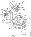
- the Fig. 1 shows a robot 1 with a robot controller 2 and a robot arm 3.
- the robot arm 3 has a base frame 5 as a first link G1, on which a carousel 7 as a second link G2 is rotatably mounted about a first vertical axis A1 and driven in rotation by means of a first drive motor M1 is.
- the axes A1-A6 of the robot arm 3 can also be referred to as joints L1-L6 of the robot arm 3.
- a rocker 9 is mounted as a third link G3 so that it can pivot up and down about a second horizontal axis A2 and is driven in rotation by means of a second drive motor M2.
- the rocker 9 carries an arm extension 11 which is mounted so that it can pivot up and down about a third horizontal axis A3 and is driven in rotation by means of a third drive motor M3.
- the base arm of which forms a fourth link G4 a fourth axis A4 is provided, which runs in the longitudinal extension of the arm extension 11 and, via a fourth drive motor M4, a hand 15, which forms a forearm of the arm extension 11 and represents a fifth link G5 , rotary drives.
- a first leg and a second leg extend forward in the form of a fork.
- the two legs carry a bearing for a free end 13 of the hand 15, which forms a sixth link G6.
- the mounting defines a fifth axis A5 of the robot arm 3, about which the hand 15 can be pivoted by means of a fifth drive motor M5.
- the hand 15 has a sixth axis A6 in order to be able to drive a fastening flange 16, which forms a seventh link G7, in a rotatable manner by means of a sixth drive motor M6.
- Each axis A1 to A6 is assigned a joint L1 to L6, which joint L1 to L6 in the case of the exemplary embodiment shown connect the links G1 to G7 in the manner of serial kinematics.
- the Fig. 2 shows part of an energy conduction strand 17 of the robot arm 3, which is designed to transmit drive energy to the at least one drive motor M1-M6.
- the energy conduction strand 17 has an intermediate strand section 17.3 running between a first strand section 17.1 of the energy conduction strand 17 and a second strand section 17.2 of the energy conduction strand 17, which runs outside a first hollow structural part 18 and outside a second hollow structural part 19.
- At least the intermediate strand section 17.3 is provided with a protective tube 20 in the case of the present exemplary embodiment.
- the intermediate strand section 17.3 is enclosed in a line housing 21.
- the cable housing 21 is described for an individual intermediate strand section 17.3 between a representative first link G4 or the first hollow structural part 18 and a representative second link G3 or the second hollow structural part 19.
- the first link and the second link can, however, independently of their numbering used be formed by any, in particular directly adjacent, any links G1-G7 of the robot arm 3 and in this respect also occur several times in other embodiments than that shown with several line housings on a single robot arm 3.
- the links G1-G7 of the robot arm 3 are designed as hollow structural parts 18, 19, it may be appropriate or even necessary, for example due to the design of the joints L1-L6, the construction of gears and the arrangement of the drive motors M1-M6 an energy conduction strand 17 guided within one of the hollow links G1-G7 in the area of one or more of the joints L1-L6, as representative in FIG Fig. 2 shown, the robot arm 3 is guided out of a first link, ie from a first hollow structural part 18, outside the links G1-G7 or outside the hollow structural parts 18, 19 around the joint in question and then into the immediately following second link, that is, is introduced into the second hollow structural part 19 again.
- a first link ie from a first hollow structural part 18, outside the links G1-G7 or outside the hollow structural parts 18, 19 around the joint in question and then into the immediately following second link, that is, is introduced into the second hollow structural part 19 again.
- the intermediate section 17.3 of the power cable harness 17 is largely unprotected outside the robot arm 3. Since the robot arm 3 according to the invention has the cable housing 21 enclosing the intermediate cable harness 17.3, the intermediate section 17.3 or the power cable harness 17 can protect against external influences from the working environment of the robot 1 can be protected.
- the cable housing 21 is on the one hand rigidly connected to the first hollow structural part 18 and on the other hand is mounted so as to be adjustable relative to the second hollow structural part 19.
- a rigid connection of the line housing 21 to the first hollow structural part 18 takes place in the case of the illustrated Exemplary embodiment by means of a flange connection 22.
- the flange connection 22 comprises detachable fastening means 24, in particular screws, by means of which the line housing 21 is connected to the first hollow structural part 18.
- the first hollow structural part 18 can have a flange surface 23 on its outer jacket wall and the line housing 21 can have a counter-flange surface corresponding to the flange surface 23.
- An adjustable mounting of the line housing 21 with respect to the second hollow structural part 19 takes place in the case of the illustrated embodiment in that the line housing 21 is mounted on the second hollow structural part 19 by means of a pivot bearing 25.
- a rotary bearing 25 can be designed to primarily or exclusively ensure a coaxial alignment of the line housing 21 and the second hollow structural part 19.
- the axis of rotation of the pivot bearing 25 is in particular precisely aligned with the axis of rotation of that joint L3 of the robot arm 3 which rotatably connects the first hollow structural part 18 to the second hollow structural part 19.
- the cable housing 21 has a housing shell 21 a with an inlet opening 26, via which the intermediate strand section 17. 3 emerging from the first hollow structural part 18 enters the cable housing 21.
- the housing shell 21a has an outlet opening 27, via which the intermediate strand section 17.3 exits the line housing 21 and then enters the second hollow structural part 19, the housing shell 21a having a flange 28 surrounding the inlet opening 26, which is used for rigidly attaching the housing shell 21a is formed on the first hollow structural part 18.
- the cover 29 closes a maintenance opening 29a of the line housing 21 or the housing shell 21a.
- the flange 28 surrounding the inlet opening 26 represents the rigid connection of the line housing 21 to the first hollow structural part 18.
- This flange 28 has the releasable fastening means 24, in particular the screws, through which the line housing 21 is connected to the first hollow structural part 18 is connected in the region of the inlet opening 26.
- the first hollow structural part 18 can have on its outer jacket wall the flange surface 23 surrounding the inlet opening 26 and the line housing 21 can have a counter-flange surface corresponding to the flange surface 23 and surrounding the inlet opening 26.
- the outlet opening 27 is a circular opening which is arranged coaxially to the axis of rotation of the associated joint L3.
- the outlet opening 27 is a circular opening which is arranged coaxially to the rotary bearing 25, which primarily or exclusively ensures a coaxial alignment of the line housing 21 and the second hollow structural part 19.
- the axis of rotation of the pivot bearing 25 is in particular precisely aligned with the axis of rotation of that joint L3 of the robot arm 3 which rotatably connects the first hollow structural part 18 to the second hollow structural part 19.
- the outlet opening 27 can have the ring 31 described below or the outlet opening 27 can be a circular opening which is arranged coaxially to this ring 31.
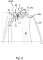
- the Fig. 3 and Fig. 4 show variants in which the housing shell 21a has a ring 31 running around the outlet opening 27, which is part of a bearing arrangement of the robot arm 3 that rotatably supports the housing shell 21a on the second hollow structural part 19 and at the same time part of a sealing arrangement of the Robot arm 3 forms.
- the ring 31 is produced as a separate component and fastened to the housing shell 21a.
- the ring 31 shows according to the variant Fig. 3 a raceway 32 on which the rolling elements 33 of a rolling bearing arrangement of the robot arm 3 which rotatably supports the housing shell 21a on the second hollow structural part 19 roll.
- the rolling bodies 33 are guided in a groove 34 of the second hollow structural part 19.
- the roller bearing arrangement is designed in particular to ensure primarily or exclusively a coaxial alignment of the line housing 21 or housing shell 21a and the second hollow structural part 19.
- the ring 31 shows according to the variant Fig. 4
- a slide 35 on which a guide belt 36, mounted in the second hollow structural part 19, of a slide bearing arrangement of the robot arm 3 that rotatably supports the housing shell 21a on the second hollow structural part 19 runs.
- the ring 31 also has a sealing membrane 37 on which a sealing lip 38a, 38b of a sealing arrangement of the robot arm 3 that seals the housing shell 21a against the second hollow structural part 19 rests.
- the sealing arrangement can have a radial shaft sealing ring 39 fixed in the second hollow structural part 19, which has a dynamic sealing lip 38a, the sealing edge of which rests on the sealing membrane 37 in order to seal the line housing 21 or the housing shell 21a against the second hollow structural part 19.
- the sealing arrangement has an O-ring 41 inserted in a groove 40 of the second hollow structural part 19, which is guided around a sealing lip band 42 which has at least one, in particular three sealing lips 38b, which rest on the sealing membrane 37 in order to surround the cable housing 21 or to seal the housing shell 21a against the second hollow structural part 19.
- the Fig. 5 shows an embodiment in which the protective hose 20 has a first protective hose end 20.1, and the cable housing 21, in particular the housing shell 21a, has a rotary bearing 43 which is designed to support the first protective hose end 20.1 rotatably on the cable housing 21, in particular on the housing shell 21a .
- the rotary bearing 43 has a bearing seat 44 which is fastened to the line housing 21 or to the housing shell 21a and in which the first protective hose end 20.1 is rotatably mounted.
- the bearing seat 44 is designed as a sheet metal bushing which has a fastening section 44.1 and an annular section 44.2 which forms the bearing seat.
- the fastening section 44.1 has holes through which screws 45 are passed, which fasten the sheet metal bushing to the cable housing 21 or to the housing shell 21a.
- the ring section 44.2 can have at least one ring projection, which is formed in ribs, on an inwardly facing jacket wall 46 of the first protective hose end 20.1 rotatably but firmly in the axial direction to engage.
- the Fig. 6 shows an embodiment in which the protective hose 20 has a second protective hose end 20.2, and a clamp 47 is provided which is designed to rigidly attach the second protective hose end 20.2 to the first hollow structural part 18 and the second hollow structural part 19, respectively.
- the clamp 47 has a sheet metal tab 47a to which the second protective hose end 20.2 is rigidly attached.
- the sheet metal tab 47a can have a fastening section 48 and a separable ring clip 49 to which the second protective hose end 20.2 is clamped.
- the fastening section 48 has at least one hole through which a screw 50 is passed, which fastens the clamp 47 to the second hollow structural part 19.
- the divisible ring clamp 49 can have a pivotable bracket 49a which is designed to clamp the second protective hose end 20.2 in a rotationally fixed manner and in the axial direction.
Landscapes
- Engineering & Computer Science (AREA)
- Robotics (AREA)
- Mechanical Engineering (AREA)
- Manipulator (AREA)
Description
- Die Erfindung betrifft einen Roboter, aufweisend einen Roboterarm mit mehreren durch Glieder verbundenen Gelenken, die von Antriebsmotoren des Roboters, welche an die Gelenke angekoppelt sind, gemäß eines Roboterprogramms automatisiert oder in einem Handfahrbetrieb des Roboters antriebsgesteuert verstellbar sind, um die Konfiguration des Roboterarms zu verändern, wobei ein erstes Glied mit einem zweiten Glied durch wenigstens ein Gelenk verbunden ist, über das ein Energieleitungsstrang des Roboterarms, der ausgebildet ist, Antriebsenergie an den wenigstens einen Antriebsmotor zu übertragen, hinweggeführt ist.
- Die
DE 10 2012 200 186 A1 und dieUS 5,732,599 beschreiben jeweils einen Roboterarm, bei dem ein zwischen einem ersten und zweiten Armabschnitt gebildetes Gelenk ein das kompakte Design des Roboterarms unterstützendes Leitungsgehäuse aufweist, welches eine schützende Abdeckung für Leitungen bildet, die aus dem ersten Armabschnitt herausgeführt, um das Gelenk herumgeführt und in den zweiten Armabschnitt hineingeführt sind. - Aufgabe der Erfindung ist es, einen Roboter zu schaffen, dessen Energieleitungsstrang besonders gut gegen äußere Einflüsse seiner Arbeitsumgebung geschützt ist.
- Diese Aufgabe wird erfindungsgemäß gelöst durch eine Roboter, aufweisend einen Roboterarm mit mehreren durch Glieder verbundenen Gelenken, die von Antriebsmotoren des Roboters, welche an die Gelenke angekoppelt sind, gemäß eines Roboterprogramms automatisiert oder in einem Handfahrbetrieb des Roboters antriebsgesteuert verstellbar sind, um die Konfiguration des Roboterarms zu verändern, wobei ein erstes Glied mit einem zweiten Glied durch wenigstens ein Gelenk verbunden ist, über das ein Energieleitungsstrang des Roboterarms, der ausgebildet ist, Antriebsenergie an den wenigstens einen Antriebsmotor zu übertragen, hinweggeführt ist, wobei:
- das erste Glied ein erstes hohles Strukturteil aufweist, innerhalb dem ein erster Strangabschnitt des Energieleitungsstrangs geführt ist,
- das zweite Glied ein zweites hohles Strukturteil aufweist, innerhalb dem ein zweiter Strangabschnitt des Energieleitungsstrangs geführt ist,
- der Energieleitungsstrang einen zwischen dem ersten Strangabschnitt des Energieleitungsstrangs und dem zweiten Strangabschnitt des Energieleitungsstrangs verlaufenden Zwischenstrangabschnitt aufweist, der außerhalb des ersten hohlen Strukturteils und außerhalb des zweiten hohlen Strukturteils verläuft,
- der Roboterarm ein den Zwischenstrangabschnitt einschließendes Leitungsgehäuse aufweist, und wobei das Leitungsgehäuse eine Gehäuseschale mit einer Eintrittsöffnung aufweist, über welche der aus dem ersten hohlen Strukturteil austretende Zwischenstrangabschnitt in das Leitungsgehäuse eintritt und die Gehäuseschale eine Austrittsöffnung aufweist, über welche der Zwischenstrangabschnitt aus dem Leitungsgehäuse austritt und dann in das zweite hohle Strukturteil eintritt, wobei die Gehäuseschale einen die Eintrittsöffnung umgebenden Flansch aufweist, der zum starren Befestigen der Gehäuseschale an dem ersten hohlen Strukturteil ausgebildet ist, und die Gehäuseschale einen um die Austrittsöffnung umlaufenden Ring aufweist, welcher Teil einer die Gehäuseschale am zweiten hohlen Strukturteil drehbar lagernden Lageranordnung des Roboterarms und/oder Teil einer die Gehäuseschale gegen das zweite hohle Strukturteil abdichtenden Dichtungsanordnung des Roboterarms bildet, und wobei der Energieleitungsstrang einen den Zwischenstrangabschnitt einfassenden Schutzschlauch aufweist, der ein erstes Schutzschlauchende aufweist, und die Gehäuseschale ein Drehlager aufweist, das ausgebildet ist, das erste Schutzschlauchende drehbar an der Gehäuseschale zu lagern.
- Der Roboter kann ein sogenannter Knickarmroboter sein, dessen Roboterarm ein Grundgestell als ein Glied aufweist, an dem ein Karussell als folgendes Glied um eine vertikale Achse drehbar gelagert und mittels eines ersten Antriebsmotors drehangetrieben ist. An dem Karussell kann eine Schwinge als weiteres Glied um eine zweite horizontale Achse auf und ab schwenkbar gelagert und mittels eines zweiten Antriebsmotors drehangetrieben sein. Die Schwinge trägt einen Armausleger, der um eine dritte horizontale Achse auf und ab schwenkbar gelagert und mittels eines dritten Antriebsmotors drehangetrieben ist. An dem Armausleger, dessen Grundarm ein weiteres Glied bildet, kann eine vierte Achse vorgesehen sein, welche in Längserstreckung des Armauslegers verläuft und über einen vierten Antriebsmotors eine Roboterhand, die einen Vorderarm des Armauslegers bildet und ein weiteres Glied darstellt, drehantreibt ist. Von der Roboterhand kann sich ein erster Schenkel und ein zweiter Schenkel gabelförmig nach vorne erstrecken. Die beiden Schenkel tragen eine Lagerung für ein freies Ende der Roboterhand, das ein vorletztes Glied bildet. Die Lagerung definiert eine fünfte Achse des Roboterarms, um welche die Roboterhand mittels eines fünften Antriebsmotors schwenkbar bewegt werden kann. Ergänzend weist die Roboterhand eine sechste Achse auf, um einen Befestigungsflansch, der ein letztes Glied bildet, mittels eines sechsten Antriebsmotors drehbar antreiben zu können.
- Jedes der Gelenke kann als ein Drehgelenk ausgebildet sein. Jedes Glied ist ausgebildet, Kräfte und Momente, welche insbesondere von einem Greifer oder Werkzeug, das durch den Roboter gehandhabt, insbesondere bewegt wird, über einen Werkzeugbefestigungsflansch des Roboterarms in den Roboterarm, d.h. in seine Struktur eingeleitet wird, von einem Gelenk an ein folgendes Gelenk weiterzuleiten. Daneben müssen auch Kräfte und Momente, welche von der Eigengewichtskraft des Roboterarms stammen, in das Grundgestell des Roboterarms weitergeleitet werden. Jedes Glied des Roboterarms weist dazu mindestens ein Strukturteil auf, das ausgebildet ist, diese Kräfte und Momente aufnehmen und weiterleiten zu können. Im Allgemeinen ist ein solches Strukturteil hohl ausgebildet und kann beispielsweise von einem Metallgussteil oder einer geschweißten Stahlkonstruktion bestehen, welche beispielsweise Rohrabschnitte aufweisen kann. Jedes Glied ist über eines der Gelenke mit einem unmittelbar folgenden Glied des Roboterarms verbunden, insbesondere drehbar verbunden. Dazu kann das jeweilige Gelenk ein Drehlager aufweisen. Jedem Drehlager kann eine Dichtungsanordnung, wie beispielsweise ein Radialwellendichtring zugeordnet sein. An jedes Gelenk bzw. jedes Drehlager kann ein eigener Antriebsmotor, wie beispielsweise ein Elektromotor, insbesondere ein Servomotor, mit zughöriger Antriebssteuerung automatisch antreibbar angekoppelt sein. Die Antriebe werden im Allgemeinen von einer Robotersteuerung des Roboters angesteuert. Durch die Robotersteuerung können die Gelenke mittels der Antriebe gemäß eines Roboterprogramms automatisiert oder in einem Handfahrbetrieb des Roboters antriebsgesteuert verstell werden, um die Konfiguration des Roboterarms zu verändern. Unter einer Konfiguration wird die Menge der momentanen, einzelnen Achswinkelstellungen der Gelenke des Roboterarms verstanden.
- Um die Antriebsmotoren durch die Robotersteuerung ansteuern zu können, ist die Robotersteuerung über einen Energieleitungsstrang mit allen Antriebsmotoren verbunden. Im Falle von elektrischen Antriebsmotoren kann der Energieleitungsstrang von einem Bündel von mehreren elektrischen Leitungen gebildet werden, wobei jeweils mindestens eine elektrische Leitung zu jeweils einem der Antriebsmotoren führt. Da im Allgemeinen ein solcher Energieleitungsstrang über ein Grundgestell des Roboterarms eingeführt und entlang des Roboterarms bis zum Antriebsmotor des letzten, d.h. des distalen Endgelenks geführt wird, läuft der Energieleitungsstrang mit entsprechenden Leitungsabzweigungen und einhergehenden Leitungsquerschnittsverringerungen entlang bzw. durch den gesamten Roboterarm. Je nach Bauart des Roboterarms kann der Energieleitungsstrang vollständig innerhalb der hohlen Glieder, d.h. der hohlen Strukturteile des Roboterarms verlegt sein oder außen entlang der Glieder, d.h. der Strukturteile des Roboterarms verlegt sein, die dann nicht zwingend hohl sein müssen.
- Auch wenn die Glieder des Roboterarms als hohle Strukturteile ausgebildet sind, kann es beispielsweise aufgrund der Bauart der Gelenke, der Konstruktion von Getrieben und der Anordnung der Antriebsmotoren zweckmäßig oder sogar erforderlich sein, dass ein innerhalb eines der hohlen Glieder geführter Energieleitungsstrang im Bereich eines oder mehrerer der Gelenke des Roboterarms aus einem ersten Glied, d.h. aus einem ersten hohlen Strukturteil herausgeführt wird, außerhalb der Glieder bzw. außerhalb der hohlen Strukturteile um das betreffende Gelenk herumgeführt wird und anschließend in das unmittelbar folgende zweite Glied, d.h. in das zweite hohle Strukturteil wieder eingeleitet wird.
- Bei einer solchen Bauart liegen dann allerdings wenigstens ein Zwischenabschnitt oder sogar mehrere Zwischenabschnitte des Energieleitungsstrangs weitgehend ungeschützt außerhalb des Roboterarms.
- Indem der Roboterarm erfindungsgemäß ein den Zwischenstrangabschnitt einschließendes Leitungsgehäuse aufweist, kann der eine Zwischenabschnitt oder die mehreren Zwischenabschnitte des Energieleitungsstrangs besonders gut gegen äußere Einflüsse der Arbeitsumgebung des Roboters geschützt werden.
- Das Leitungsgehäuse schließt insoweit den außerhalb des Roboterarms verlaufenden Zwischenstrangabschnitt ein, derart, dass aus der Arbeitsumgebung auf den Roboterarm einwirkende Feststoffe, wie beispielsweise Stäube, und/oder Flüssigkeiten, wie beispielsweise Wasser, Reinigungsmittel oder Lösungsmittel, und/oder gasförmige Stoffe nicht in das Leitungsgehäuse eindringen können und somit der außerhalb des Roboterarms verlaufende Zwischenstrangabschnitt nicht mit diesen Stoffen in Kontakt kommen kann. So kann die Lebensdauer und Betriebssicherheit des Roboters verbessert werden, insbesondere in unwirtlichen Arbeitsumgebungen. Das Leitungsgehäuse kann abgedichtet an einem der Glieder es Roboterarms befestigt sein. Weist der Roboterarm mehrere außerhalb des Roboterarms verlaufende Zwischenstrangabschnitte auf, so kann jedem Zwischenstrangabschnitte ein separates Leitungsgehäuse zugeordnet sein.
- Das wenigstens eine Leitungsgehäuse ist demgemäß ein sich von den Gliedern des Roboterarms, d.h. von den hohlen Strukturbauteilen verschiedenes Bauteil. Das Leitungsgehäuse ist also kein tragendes Glied des Roboterarms. Das Leitungsgehäuse nimmt insoweit keine tragende Funktion wahr, um die Glieder des Roboterarms in einer bestimmten Konfiguration, d.h. Gelenkstellungen zu halten. Vielmehr werden von dem Leitungsgehäuse keine diesbezüglichen Kräfte und/oder Momente übertragen. Das Leitungsgehäuse ist somit lediglich dazu ausgebildet, einen außerhalb des eigentlichen Roboterarms, der durch die Glieder und Gelenke gebildet wird, liegenden Zwischenstrangabschnitt gegenüber der Umgebung abzudichten.
- Das Leitungsgehäuse ist insbesondere dazu ausgebildet, einen Zwischenstrangabschnitt des Energieleitungsstrangs abzudichten, der außerhalb eines Gelenks des Roboterarms entlanggeführt ist, das ein erstes Glied des Roboterarms unmittelbar mit einem zweiten Glied des Roboterarms verbindet. Der Energieleitungsstrang läuft dabei insoweit zunächst innerhalb des ersten hohlen Strukturbauteils des ersten Glieds, ist aus diesem ersten hohlen Strukturbauteil herausgeführt, läuft dann außerhalb des Roboterarms als der Zwischenstrangabschnitt außerhalb des betreffenden Gelenks herum und taucht dann in das zweite hohle Strukturbauteil des zweiten Glieds hinein. Zwischen dem ersten Glied und dem zweiten Glied ist insoweit kein zusätzliches Glied, wie ein Zwischenglied vorhanden. Eine Übertragung von Kräften und/oder Momenten, um die Glieder des Roboterarms in einer bestimmten Konfiguration, d.h. Gelenkstellungen zu halten, erfolgt also nur über dasjenige Gelenk, welches das erste Glied unmittelbar mit dem zweiten Glied verbindet und nicht über das Leitungsgehäuse.
- Das Leitungsgehäuse kann außen an dem einen hohlen Strukturbauteil, beispielsweise des ersten Gelenks, befestigt sein, insbesondere abgedichtet befestigt sein und von außen an dem anderen hohlen Strukturbauteil, beispielsweise des zweiten Gelenks mittels eine Lagerung und/oder einer Dichtungsvorrichtung drehbar gelagert sein. Die Dichtungsvorrichtung dichtet dabei einen Innenraum des Leitungsgehäuses gegenüber der Umgebung ab. Die Lagerung und/oder die Dichtungsvorrichtung fluchtet dabei in axialer Richtung mit der Drehachse des zugeordneten Gelenks.
- Das Leitungsgehäuse kann beispielsweise eine starre Gehäuseschale sein, die als ein Tiefziehteil, ein Metallgussteil, insbesondere ein Aluminiumgussteil, oder als ein Kunststoffspritzgussteil hergestellt sein kann. Das Leitungsgehäuse ist insbesondere derart gestaltet, dass es resistent ist gegen die einwirkenden Stoffe der Arbeitsumgebung, wie die genannten Stäube, und/oder Flüssigkeiten, wie beispielsweise Wasser, Reinigungsmittel oder Lösungsmittel, und/oder gasförmige Stoffe, aber insbesondere aus Kostengründen nur eine maximale Festigkeit aufweist, die nicht geeignet ist, als ein tragendes Strukturteil dienen zu können. Anders ausgedrückt kann das Leitungsgehäuse aus einem Material geringer Festigkeit und geringer Wandstärke hergestellt sein, die deutlich kleiner ist, als dies erforderlich wäre, um Kräfte und Momente, welche insbesondere von einem Greifer oder Werkzeug, das durch den Roboter gehandhabt, insbesondere bewegt wird, über einen Werkzeugbefestigungsflansch des Roboterarms in den Roboterarm, d.h. in seine Struktur eingeleitet werden, über das Leitungsgehäuse abstützen bzw. weiterleiten zu können. Dies gilt auch hinsichtlich der Kräfte und Momente, welche von der Eigengewichtskraft des Roboterarms stammen, und die in das Grundgestell des Roboterarms weitergeleitet werden müssen, jedoch nicht über das Leitungsgehäuse geführt werden.
- Im Folgenden wird das Leitungsgehäuse für einen einzelnen Zwischenstrangabschnitt zwischen einem repräsentativen ersten Glied bzw. einem ersten hohlen Strukturteil und einem repräsentativen zweiten Glied bzw. einem zweiten hohlen Strukturteil beschrieben. Das erste Glied und das zweite Glied können jedoch unabhängig ihrer verwendeten Nummerierung von beliebigen, insbesondere unmittelbar benachbarten beliebigen Gliedern des Roboterarms gebildet werden und insoweit in speziellen Ausführungsformen bei mehreren Leitungsgehäusen an einem einzigen Roboterarm auch mehrfach auftreten.
- Das Leitungsgehäuse ist einerseits mit dem ersten hohlen Strukturteil starr verbunden und andererseits relativ zum zweiten hohlen Strukturteil verstellbar gelagert.
- Eine starre Verbindung des Leitungsgehäuses mit dem ersten hohlen Strukturteil kann mittels einer Flanschverbindung erfolgen. Die Flanschverbindung kann lösbare Befestigungsmittel, insbesondere Schrauben umfassen, durch welche das Leitungsgehäuses mit dem ersten hohlen Strukturteil verbunden ist. Dabei kann das erste hohle Strukturteil an seiner äußeren Mantelwand eine Flanschfläche aufweisen und das Leitungsgehäuse eine der Flanschfläche entsprechende Gegenflanschfläche aufweisen. Zwischen der Flanschfläche des ersten hohlen Strukturteils und der Gegenflanschfläche des Leitungsgehäuses kann eine Dichtung, insbesondere eine statische Dichtung eingefügt sein. Die Dichtung kann beispielsweise eine Flachdichtung aus elastischem Kunststoff oder Papier sein. Im Falle einer starren Verbindung von Leitungsgehäuses und erstem hohlen Strukturteil mittels Schrauben können beispielsweise der Flanschfläche des ersten hohlen Strukturteils mehrere Gewindebohrungen zugeordnet sein und der Gegenflanschfläche des Leitungsgehäuses eine entsprechende Anzahl von Durchgangsbohrungen zugeordnet sein, wobei Schrauben durch die Durchgangsbohrungen des Leitungsgehäuses hindurch gesteckt sind, welche mit ihren Gewindeabschnitten in die Gewindebohrungen des ersten hohlen Strukturteils eingeschraubt sind, um das Leitungsgehäuse gegen das erste hohle Strukturteil festzuschrauben.
- Eine verstellbare Lagerung des Leitungsgehäuses bezüglich des zweiten hohlen Strukturteils kann im Falle eines drehbaren Gelenks des Roboterarms dadurch erfolgen, dass das Leitungsgehäuse mittels eines Drehlagers an dem zweiten hohlen Strukturteil gelagert ist. Ein solches Drehlager kann ausgebildet sein, vorrangig oder ausschließlich eine koaxiale Ausrichtung von Leitungsgehäuse und zweitem hohlen Strukturteil sicherzustellen. So fluchtet die Drehachse des Drehlagers insbesondere genau mit der Drehachse desjenigen Gelenks des Roboterarms, welches das erste hohle Strukturteil mit dem zweiten hohlen Strukturteil drehbar verbindet.
- Das Leitungsgehäuse weist eine Gehäuseschale mit einer Eintrittsöffnung auf, über welche der aus dem ersten hohlen Strukturteil austretende Zwischenstrangabschnitt in das Leitungsgehäuse eintritt und die Gehäuseschale kann dabei eine Austrittsöffnung aufweisen, über welche der Zwischenstrangabschnitt aus dem Leitungsgehäuse austritt und dann in das zweite hohle Strukturteil eintritt, wobei die Gehäuseschale einen die Eintrittsöffnung umgebenden Flansch aufweist, der zum starren Befestigen der Gehäuseschale an dem ersten hohlen Strukturteil ausgebildet ist.
- Das Leitungsgehäuse bzw. die Gehäuseschale kann ausgebildet sein, außer der Eintrittsöffnung, der Austrittsöffnung und gegebenenfalls einer optionalen Wartungsöffnung, die von einem Deckel verschlossen ist, keine sonstigen Öffnungen aufzuweisen. Ist die eine optionale Wartungsöffnung von dem Deckel verschlossen bzw. sind mehrere Wartungsöffnungen von einer entsprechenden Anzahl von Deckeln verschlossen, und die Eintrittsöffnung an das erste hohle Strukturteil abgedichtet angeschlossen und die Austrittsöffnung an das zweite hohle Strukturteil abgedichtet angeschlossen, dann ist der Zwischenstrangabschnitt durch das Leitungsgehäuse bzw. durch die Gehäuseschale gegen die Arbeitsumgebung des Roboters abgeschirmt, d.h. feste, flüssige und/oder gasförmige Stoffe aus der Arbeitsumgebung können nicht zu dem Zwischenstrangabschnitt vordringen. Die äußere Mantelwand des ersten hohlen Strukturteils, die äußere Mantelwand des zweiten hohlen Strukturteils und das Leitungsgehäuse bzw. die Gehäuseschale, gegebenenfalls mit den optionalen Deckeln begrenzen abgedichtet folglich eine außerhalb des Roboterarms angeordnete Hohlkammer, in welcher der Zwischenstrangabschnitt vor äußeren Einflüssen geschützt verläuft.
- Der die Eintrittsöffnung umgebenden Flansch kann die starre Verbindung des Leitungsgehäuses mit dem ersten hohlen Strukturteil darstellen. Dieser Flansch kann lösbare Befestigungsmittel, insbesondere Schrauben umfassen, durch welche das Leitungsgehäuses mit dem ersten hohlen Strukturteil im Bereich der Eintrittsöffnung verbunden ist. Dabei kann das erste hohle Strukturteil an seiner äußeren Mantelwand eine die Eintrittsöffnung umgebende Flanschfläche aufweisen und das Leitungsgehäuse eine der Flanschfläche entsprechende, die Eintrittsöffnung umgebende Gegenflanschfläche aufweisen. Zwischen der Flanschfläche des ersten hohlen Strukturteils und der Gegenflanschfläche des Leitungsgehäuses kann eine Dichtung, insbesondere eine statische Dichtung eingefügt sein, welche die Eintrittsöffnung einfasst. Die Dichtung kann beispielsweise eine Flachdichtung aus elastischem Kunststoff oder Papier sein. Im Falle einer starren Verbindung von Leitungsgehäuses und erstem hohlen Strukturteil mittels Schrauben können beispielsweise der Flanschfläche des ersten hohlen Strukturteils mehrere, die Eintrittsöffnung umgebende Gewindebohrungen zugeordnet sein und der Gegenflanschfläche des Leitungsgehäuses eine entsprechende Anzahl von die Eintrittsöffnung umgebende Durchgangsbohrungen zugeordnet sein, wobei Schrauben durch die Durchgangsbohrungen des Leitungsgehäuses hindurch gesteckt sind, welche mit ihren Gewindeabschnitten in die Gewindebohrungen des ersten hohlen Strukturteils eingeschraubt sind, um das Leitungsgehäuse gegen das erste hohle Strukturteil festzuschrauben.
- Die Austrittsöffnung kann eine Kreisöffnung sein, welche koaxial zur Drehachse des zugeordneten Gelenks angeordnet ist. Die Austrittsöffnung kann eine Kreisöffnung sein, welche außerdem koaxial zum Drehlager angeordnet ist, das vorrangig oder ausschließlich eine koaxiale Ausrichtung von Leitungsgehäuse und zweitem hohlen Strukturteil sicherstellt. Dabei kann die Drehachse des Drehlagers insbesondere genau mit der Drehachse desjenigen Gelenks des Roboterarms fluchten, welches das erste hohle Strukturteil mit dem zweiten hohlen Strukturteil drehbar verbindet. Die Austrittsöffnung kann den im Folgenden noch beschriebenen Ring aufweisen bzw. die Austrittsöffnung kann eine Kreisöffnung sein, welche koaxial zu diesem Ring angeordnet ist.
- Die Gehäuseschale weist des Weiteren erfindungsgemäß einen um die Austrittsöffnung umlaufenden Ring auf, welcher Teil einer die Gehäuseschale am zweiten hohlen Strukturteil drehbar lagernden Lageranordnung des Roboterarms und/oder Teil einer die Gehäuseschale gegen das zweite hohle Strukturteil abdichtenden Dichtungsanordnung des Roboterarms bildet.
- Der Ring kann einteilig mit der Gehäuseschale ausgebildet sein. Alternativ kann der Ring als separates Bauteil hergestellt und an der Gehäuseschale befestigt sein. Der Ring kann insbesondere aus Edelstahl hergestellt sein.
- Der Ring kann eine Laufbahn aufweisen, auf der Wälzkörper einer die Gehäuseschale am zweiten hohlen Strukturteil drehbar lagernden Wälzlageranordnung des Roboterarms abwälzen. Die Laufbahn ist dabei Teil einer die Gehäuseschale am zweiten hohlen Strukturteil drehbar lagernden Wälzlageranordnung des Roboterarms. In einer solchen Ausführungsvariante kann der Ring insoweit einen Innenring eines Wälzlagers bilden. Die Wälzkörper können Wälznadeln, Wälzrollen oder Wälzkugeln sein. Die Wälzkörper können in einem Wälzlagerkäfig angeordnet und in einer Nut des zweiten hohlen Strukturteils geführt sein. Die Wälzlageranordnung kann insbesondere ausgebildet sein, vorrangig oder ausschließlich eine koaxiale Ausrichtung von Leitungsgehäuse bzw. Gehäuseschale und zweitem hohlen Strukturteil sicherzustellen.
- Alternativ oder ergänzend zu einer Laufbahn kann der Ring eine Gleitbahn aufweisen, auf der ein im zweiten hohlen Strukturteil gelagertes Führungsband einer die Gehäuseschale am zweiten hohlen Strukturteil drehbar lagernden Gleitlageranordnung des Roboterarms läuft. Die Gleitbahn ist dabei Teil einer die Gehäuseschale am zweiten hohlen Strukturteil drehbar lagernden Gleitlageranordnung des Roboterarms. Das Führungsband kann in einer Nut des zweiten hohlen Strukturteils geführt sein. Das Führungsband kann insbesondere ausgebildet sein, vorrangig oder ausschließlich eine koaxiale Ausrichtung von Leitungsgehäuse bzw. Gehäuseschale und zweitem hohlen Strukturteil sicherzustellen.
- Alternativ oder ergänzend zu einer Laufbahn und/oder einer Gleitbahn kann der Ring eine Dichtungsbahn aufweisen, auf der eine Dichtlippe einer die Gehäuseschale gegen das zweite hohle Strukturteil abdichtenden Dichtungsanordnung des Roboterarms anliegt. Die Dichtungsbahn ist dabei Teil einer die Gehäuseschale gegen das zweite hohle Strukturteil abdichtenden Dichtungsanordnung des Roboterarms. Die Dichtungsanordnung kann einen im zweite hohle Strukturteil festgelegten Radialwellendichtring aufweisen, der eine dynamische Dichtlippe aufweist, dessen Dichtungskante auf der Laufbahn anliegt, um das Leitungsgehäuse bzw. die Gehäuseschale gegen das zweite hohle Strukturteil abzudichten. Alternativ zu einem Radialwellendichtring kann die Dichtungsanordnung einen in einer Nut des zweiten hohlen Strukturteils eingesetzten O-Ring aufweisen, welcher um ein Dichtlippenband geführt ist, das wenigstens eine, insbesondere drei Dichtlippen aufweist, die auf der Laufbahn anliegen, um das Leitungsgehäuse bzw. die Gehäuseschale gegen das zweite hohle Strukturteil abzudichten.
- In allen Ausführungsvarianten kann das Leitungsgehäuse, insbesondere die Gehäuseschale eine Wartungsöffnung und einen die Wartungsöffnung verschließenden, demontierbaren Deckel aufweisen.
- Über die Wartungsöffnung kann der Energieleitungsstrang, insbesondere der Zwischenstrangabschnitt montiert, demontiert und/oder installiert bzw. repariert werden. Der Deckel kann lösbar an dem Leitungsgehäuse, insbesondere lösbar an der Gehäuseschale befestigt sein, beispielsweise mittels Schrauben. Der Deckel kann als ein Tiefziehteil, ein Metallgussteil, insbesondere ein Aluminiumgussteil, oder als ein Kunststoffspritzgussteil hergestellt sein kann. Der Deckel kann insbesondere derart gestaltet sein, dass er resistent ist gegen die einwirkenden Stoffe der Arbeitsumgebung, wie die genannten Stäube, und/oder Flüssigkeiten, wie beispielsweise Wasser, Reinigungsmittel oder Lösungsmittel, und/oder gasförmige Stoffe, aber insbesondere aus Kostengründen nur eine maximale Festigkeit aufweist, die nicht geeignet ist, als ein tragendes Strukturteil dienen zu können.
- Erfindungsgemäß weist der Energieleitungsstrang zusätzlich einen den Zwischenstrangabschnitt einfassenden Schutzschlauch auf.
- Der Energieleitungsstrang kann aus mehreren Einzelleitungen zusammengestellt sein, die innerhalb des Schutzschlauches zusammengefasst sein können. Der Schutzschlauch kann beispielsweise ein Wellschlauch aus Kunststoff sein.
- Der Schutzschlauch weist ein erstes Schutzschlauchende auf, und die Gehäuseschale weist erfindungsgemäß außerdem dabei ein Drehlager auf, das ausgebildet ist, das erste Schutzschlauchende drehbar an an der Gehäuseschale zu lagern.
- Das Drehlager kann dazu einen am Leitungsgehäuse bzw. an der Gehäuseschale befestigten Lagersitz aufweisen, in dem das erste Schutzschlauchende drehbar gelagert ist. Der Lagersitz kann an einer Blechbuchse ausgebildet sein, die einen Befestigungsabschnitt aufweist und einen Ringabschnitt aufweist, der den Lagersitz aufweist. Der Befestigungsabschnitt kann wenigstens ein Loch aufweisen, durch das eine Schraube hindurchgeführt ist, welche die Blechbuchse an dem Leitungsgehäuse bzw. an der Gehäuseschale befestigt. Der Ringabschnitt kann an einer nach innen weisenden Mantelwand wenigstens einen Ringvorsprung aufweisen, der ausgebildet sein kann, in Rippen des ersten Schutzschlauchendes drehbar, aber in axialer Richtung fest, einzugreifen.
- Der Schutzschlauch kann ein zweites Schutzschlauchende aufweisen, und das erste hohle Strukturteil oder das zweite hohle Strukturteil kann dabei eine Klemmschelle aufweisen, die ausgebildet ist, das zweite Schutzschlauchende starr an dem ersten hohlen Strukturteil bzw. dem zweiten hohlen Strukturteil zu befestigen.
- Die Klemmschelle kann dazu ein am zweiten hohlen Strukturteil befestigte Blechlasche aufweisen, an der das zweite Schutzschlauchende starr befestigt ist. Die Blechlasche kann einen Befestigungsabschnitt aufweisen und eine teilbare Ringschelle aufweisen, an der das zweite Schutzschlauchende festgeklemmt ist. Der Befestigungsabschnitt kann wenigstens ein Loch aufweisen, durch das eine Schraube hindurchgeführt ist, welche die Klemmschelle am zweiten hohlen Strukturteil befestigt. Die teilbare Ringschelle kann einen schwenkbaren Bügel aufweisen, der ausgebildet sein kann, das zweite Schutzschlauchende drehfest und in axialer Richtung fest einzuspannen.
- Der erste Strangabschnitt des Energieleitungsstrangs kann von Einzelleitungen gebildet werden, und jede Einzelleitung kann dabei mittels einer ersten Leitungsklemmeinrichtung in dem ersten hohlen Strukturteil separat befestigt sein.
- Alternativ oder ergänzend kann der zweite Strangabschnitt des Energieleitungsstrangs von Einzelleitungen gebildet werden, und jede Einzelleitung kann dabei mittels einer zweiten Leitungsklemmeinrichtung in dem zweiten hohlen Strukturteil separat befestigt sein.
- Konkrete Ausführungsbeispiele der Erfindung sind in der nachfolgenden Beschreibung unter Bezugnahme auf die beigefügten Figuren näher erläutert. Konkrete Merkmale dieser exemplarischen Ausführungsbeispiele können unabhängig davon, in welchem konkreten Zusammenhang sie erwähnt sind, gegebenenfalls auch einzeln oder in weiteren Kombinationen betrachtet, allgemeine Merkmale der Erfindung darstellen.
- Es zeigen:
- Fig. 1
- eine perspektivische Ansicht eines beispielhaften Roboters mit einem Roboterarm;
- Fig. 2
- eine Schnittdarstellung durch einen Roboterarm gemäß
Fig. 1 im Bereich desjenigen Gelenks, welches die Schwinge mit dem Armausleger drehbar verbindet, zusammen mit einem dortigen Zwischenstrangabschnitt eines beispielhaften Energieleitungsstrangs und einem erfindungsgemäßen Leitungsgehäuse; - Fig. 3
- eine Teilschnittansicht durch eine erste Ausführungsvariante einer drehbaren Lagerung des Leitungsgehäuses an dem zweiten hohlen Strukturteil mit Wälzkörpern und einem Radialwellendichtring;
- Fig. 4
- eine Teilschnittansicht durch eine zweite Ausführungsvariante einer drehbaren Lagerung des Leitungsgehäuses an dem zweiten hohlen Strukturteil mit einem Führungsband und einer O-Ringdichtung;
- Fig. 5
- eine Teilschnittansicht durch eine beispielhafte Ausführung einer drehbaren Lagerung eines den Zwischenstrangabschnitt einfassenden Schutzschlauches an dem ersten hohlen Strukturteil; und
- Fig. 6
- eine Teilschnittansicht durch eine beispielhafte Ausführung einer Befestigung eines den Zwischenstrangabschnitt einfassenden Schutzschlauches an dem zweiten hohlen Strukturteil.
- Die
Fig. 1 zeigt einen Roboter 1 mit einer Robotersteuerung 2 und einem Roboterarm 3. Der Roboterarm 3 weist ein Grundgestell 5 als erstes Glied G1 auf, an dem ein Karussell 7 als zweites Glied G2 um eine erste vertikale Achse A1 drehbar gelagert und mittels eines ersten Antriebsmotors M1 drehangetrieben ist. Die Achsen A1-A6 des Roboterarms 3 können auch als Gelenke L1-L6 des Roboterarms 3 bezeichnet werden. An dem Karussell 7 ist eine Schwinge 9 als drittes Glied G3 um eine zweite horizontale Achse A2 auf und ab schwenkbar gelagert und mittels eines zweiten Antriebsmotors M2 drehangetrieben. Die Schwinge 9 trägt einen Armausleger 11, der um eine dritte horizontale Achse A3 auf und ab schwenkbar gelagert und mittels eines dritten Antriebsmotors M3 drehangetrieben ist. An dem Armausleger 11, dessen Grundarm ein viertes Glied G4 bildet, ist eine vierte Achse A4 vorgesehen, welche in Längserstreckung des Armauslegers 11 verläuft und über einen vierten Antriebsmotors M4 eine Hand 15, die einen Vorderarm des Armauslegers 11 bildet und ein fünftes Glied G5 darstellt, drehantreibt. Von der Hand 15 erstrecken sich ein erster Schenkel und ein zweiter Schenkel gabelförmig nach vorne. Die beiden Schenkel tragen eine Lagerung für ein freies Ende 13 der Hand 15, das ein sechstes Glied G6 bildet. Die Lagerung definiert eine fünfte Achse A5 des Roboterarms 3, um welche die Hand 15 mittels eines fünften Antriebsmotors M5 schwenkbar bewegt werden kann. Ergänzend weist die Hand 15 eine sechste Achse A6 auf, um einen Befestigungsflansch 16, der ein siebtes Glied G7 bildet, mittels eines sechsten Antriebsmotors M6 drehbar antreiben zu können. Jeder Achse A1 bis A6 ist ein Gelenk L1 bis L6 zugeordnet, welche Gelenk L1 bis L6 im Falle des gezeigten Ausführungsbeispiels in Art einer seriellen Kinematik die Glieder G1 bis G7 verbinden. - Die
Fig. 2 zeigt einen Teil eines Energieleitungsstrangs 17 des Roboterarms 3, der ausgebildet ist, Antriebsenergie an den wenigstens einen Antriebsmotor M1-M6 zu übertragen. Der Energieleitungsstrang 17 weist einen zwischen einem ersten Strangabschnitt 17.1 des Energieleitungsstrangs 17 und einem zweiten Strangabschnitt 17.2 des Energieleitungsstrangs 17 verlaufenden Zwischenstrangabschnitt 17.3 auf, der außerhalb eines ersten hohlen Strukturteils 18 und außerhalb eines zweiten hohlen Strukturteils 19 verläuft. Zumindest der Zwischenstrangabschnitt 17.3 ist im Falle des vorliegenden Ausführungsbeispiels mit einem Schutzschlauch 20 versehen. - Der Zwischenstrangabschnitt 17.3 ist erfindungsgemäß in einem Leitungsgehäuse 21 eingeschlossen.
- Im Folgenden wird das Leitungsgehäuse 21 für einen einzelnen Zwischenstrangabschnitt 17.3 zwischen einem repräsentativen ersten Glied G4 bzw. dem ersten hohlen Strukturteil 18 und einem repräsentativen zweiten Glied G3 bzw. dem zweiten hohlen Strukturteil 19 beschrieben. Das erste Glied und das zweite Glied können jedoch unabhängig ihrer verwendeten Nummerierung von beliebigen, insbesondere unmittelbar benachbarten beliebigen Gliedern G1-G7 des Roboterarms 3 gebildet werden und insoweit in anderen Ausführungsformen als der gezeigten bei mehreren Leitungsgehäusen an einem einzigen Roboterarm 3 auch mehrfach auftreten.
- Auch wenn die Glieder G1-G7 des Roboterarms 3 als hohle Strukturteile 18, 19 ausgebildet sind, kann es beispielsweise aufgrund der Bauart der Gelenke L1-L6, der Konstruktion von Getrieben und der Anordnung der Antriebsmotoren M1-M6 zweckmäßig oder sogar erforderlich sein, dass ein innerhalb eines der hohlen Glieder G1-G7 geführter Energieleitungsstrang 17 im Bereich eines oder mehrerer der Gelenke L1-L6, wie repräsentativ in
Fig. 2 gezeigt, des Roboterarms 3 aus einem ersten Glied, d.h. aus einem ersten hohlen Strukturteil 18 herausgeführt wird, außerhalb der Glieder G1-G7 bzw. außerhalb der hohlen Strukturteile 18, 19 um das betreffende Gelenk herumgeführt wird und anschließend in das unmittelbar folgende zweite Glied, d.h. in das zweite hohle Strukturteil 19 wieder eingeleitet wird. - Bei einer solchen Bauart liegt dann der Zwischenabschnitt 17.3 des Energieleitungsstrangs 17 weitgehend ungeschützt au-βerhalb des Roboterarms 3. Indem der Roboterarm 3 erfindungsgemäß das den Zwischenstrangabschnitt 17.3 einschließendes Leitungsgehäuse 21 aufweist, kann der Zwischenabschnitt 17.3 oder des Energieleitungsstrangs 17 besonders gut gegen äußere Einflüsse der Arbeitsumgebung des Roboters 1 geschützt werden. Das Leitungsgehäuse 21 ist einerseits mit dem ersten hohlen Strukturteil 18 starr verbunden und ist andererseits relativ zum zweiten hohle Strukturteil 19 verstellbar gelagert.
- Eine starre Verbindung des Leitungsgehäuses 21 mit dem ersten hohlen Strukturteil 18 erfolgt im Falle des dargestellten Ausführungsbeispiels mittels einer Flanschverbindung 22. Die Flanschverbindung 22 umfasst in diesem gezeigten Falle lösbare Befestigungsmittel 24, insbesondere Schrauben, durch welche das Leitungsgehäuse 21 mit dem ersten hohlen Strukturteil 18 verbunden ist. Dabei kann das erste hohle Strukturteil 18 an seiner äußeren Mantelwand eine Flanschfläche 23 aufweisen und das Leitungsgehäuse 21 eine der Flanschfläche 23 entsprechende Gegenflanschfläche aufweisen.
- Eine verstellbare Lagerung des Leitungsgehäuses 21 bezüglich des zweiten hohlen Strukturteils 19 erfolgt im Falle des dargestellten Ausführungsbeispiels indem das Leitungsgehäuse 21 mittels eines Drehlagers 25 an dem zweiten hohlen Strukturteil 19 gelagert ist. Ein solches Drehlager 25 kann ausgebildet sein, vorrangig oder ausschließlich eine koaxiale Ausrichtung von Leitungsgehäuse 21 und zweitem hohlen Strukturteil 19 sicherzustellen. So fluchtet die Drehachse des Drehlagers 25 insbesondere genau mit der Drehachse desjenigen Gelenks L3 des Roboterarms 3, welches das erste hohle Strukturteil 18 mit dem zweiten hohlen Strukturteil 19 drehbar verbindet.
- Das Leitungsgehäuse 21 weist eine Gehäuseschale 21a mit einer Eintrittsöffnung 26 auf, über welche der aus dem ersten hohlen Strukturteil 18 austretende Zwischenstrangabschnitt 17.3 in das Leitungsgehäuse 21 eintritt. Darüber hinaus weist die Gehäuseschale 21a eine Austrittsöffnung 27 auf, über welche der Zwischenstrangabschnitt 17.3 aus dem Leitungsgehäuse 21 austritt und dann in das zweite hohle Strukturteil 19 eintritt, wobei die Gehäuseschale 21a einen die Eintrittsöffnung 26 umgebenden Flansch 28 aufweist, der zum starren Befestigen der Gehäuseschale 21a an dem ersten hohlen Strukturteil 18 ausgebildet ist.
- Die äußere Mantelwand des ersten hohlen Strukturteils 18, die äußere Mantelwand des zweiten hohlen Strukturteils 19 und das Leitungsgehäuse 21 bzw. die Gehäuseschale 21a begrenzen mit einem Deckel 29 abgedichtet eine außerhalb des Roboterarms 3 angeordnete Hohlkammer 30, in welcher der Zwischenstrangabschnitt 17.3 vor äußeren Einflüssen geschützt verläuft. Der Deckel 29 verschließt eine Wartungsöffnung 29a des Leitungsgehäuses 21 bzw. der Gehäuseschale 21a.
- Der die Eintrittsöffnung 26 umgebenden Flansch 28 stellt im Falle des vorliegenden Ausführungsbeispiels die starre Verbindung des Leitungsgehäuses 21 mit dem ersten hohlen Strukturteil 18 dar. Dieser Flansch 28 weist die lösbaren Befestigungsmittel 24 auf, insbesondere die Schrauben auf, durch welche das Leitungsgehäuses 21 mit dem ersten hohlen Strukturteil 18 im Bereich der Eintrittsöffnung 26 verbunden ist. Dabei kann das erste hohle Strukturteil 18 an seiner äußeren Mantelwand die die Eintrittsöffnung 26 umgebende Flanschfläche 23 aufweisen und das Leitungsgehäuse 21 eine der Flanschfläche 23 entsprechende, die Eintrittsöffnung 26 umgebende Gegenflanschfläche aufweisen.
- Die Austrittsöffnung 27 ist im Falle des vorliegenden Ausführungsbeispiels eine Kreisöffnung, welche koaxial zur Drehachse des zugeordneten Gelenks L3 angeordnet ist. Die Austrittsöffnung 27 ist eine Kreisöffnung, welche koaxial zum Drehlager 25 angeordnet ist, das vorrangig oder ausschließlich eine koaxiale Ausrichtung von Leitungsgehäuse 21 und zweitem hohlen Strukturteil 19 sicherstellt. Dabei fluchtet die Drehachse des Drehlagers 25 insbesondere genau mit der Drehachse desjenigen Gelenks L3 des Roboterarms 3, welches das erste hohle Strukturteil 18 mit dem zweiten hohlen Strukturteil 19 drehbar verbindet. Die Austrittsöffnung 27 kann den im Folgenden noch beschriebenen Ring 31 aufweisen bzw. die Austrittsöffnung 27 kann eine Kreisöffnung sein, welche koaxial zu diesem Ring 31 angeordnet ist.
- Die
Fig. 3 undFig. 4 zeigen Varianten bei denen die Gehäuseschale 21a einen um die Austrittsöffnung 27 umlaufenden Ring 31 aufweist, welcher Teil einer die Gehäuseschale 21a am zweiten hohlen Strukturteil 19 drehbar lagernden Lageranordnung des Roboterarms 3 und gleichzeitig Teil einer die Gehäuseschale 21a gegen das zweite hohle Strukturteil 19 abdichtenden Dichtungsanordnung des Roboterarms 3 bildet. - Der Ring 31 ist im Falle der gezeigten Varianten als separates Bauteil hergestellt und an der Gehäuseschale 21a befestigt. Der Ring 31 weist gemäß der Variante nach
Fig. 3 eine Laufbahn 32 auf, auf der Wälzkörper 33 einer die Gehäuseschale 21a am zweiten hohlen Strukturteil 19 drehbar lagernden Wälzlageranordnung des Roboterarms 3 abwälzen. - Die Wälzkörper 33 sind in einer Nut 34 des zweiten hohlen Strukturteils 19 geführt. Die Wälzlageranordnung ist insbesondere ausgebildet, vorrangig oder ausschließlich eine koaxiale Ausrichtung von Leitungsgehäuse 21 bzw. Gehäuseschale 21a und zweitem hohlen Strukturteil 19 sicherzustellen.
- Der Ring 31 weist gemäß der Variante nach
Fig. 4 alternativ zu Wälzkörper 33 eine Gleitbahn 35 auf, auf der ein im zweiten hohlen Strukturteil 19 gelagertes Führungsband 36 einer die Gehäuseschale 21a am zweiten hohlen Strukturteil 19 drehbar lagernden Gleitlageranordnung des Roboterarms 3 läuft. - Der Ring 31 weist außerdem in beiden Varianten eine Dichtungsbahn 37 auf, auf der eine Dichtlippe 38a, 38b einer die Gehäuseschale 21a gegen das zweite hohle Strukturteil 19 abdichtenden Dichtungsanordnung des Roboterarms 3 anliegt.
- Die Dichtungsanordnung kann einen im zweite hohle Strukturteil 19 festgelegten Radialwellendichtring 39 aufweisen, der eine dynamische Dichtlippe 38a aufweist, dessen Dichtungskante auf der Dichtungsbahn 37 anliegt, um das Leitungsgehäuse 21 bzw. die Gehäuseschale 21a gegen das zweite hohle Strukturteil 19 abzudichten.
- Alternativ zu einem Radialwellendichtring 39 weist in der Variante gemäß
Fig. 4 die Dichtungsanordnung einen in einer Nut 40 des zweiten hohlen Strukturteils 19 eingesetzten O-Ring 41 auf, welcher um ein Dichtlippenband 42 geführt ist, das wenigstens eine, insbesondere drei Dichtlippen 38b aufweist, die auf der Dichtungsbahn 37 anliegen, um das Leitungsgehäuse 21 bzw. die Gehäuseschale 21a gegen das zweite hohle Strukturteil 19 abzudichten. - Die
Fig. 5 zeigt eine Ausführungsform, bei welcher der Schutzschlauch 20 ein erstes Schutzschlauchende 20.1 aufweist, und das Leitungsgehäuse 21, insbesondere die Gehäuseschale 21a ein Drehlager 43 aufweist, das ausgebildet ist, das erste Schutzschlauchende 20.1 drehbar an dem Leitungsgehäuse 21, insbesondere an der Gehäuseschale 21a zu lagern. - Das Drehlager 43 weist im Falle des gezeigten Ausführungsbeispiels einen am Leitungsgehäuse 21 bzw. an der Gehäuseschale 21a befestigten Lagersitz 44 auf, in dem das erste Schutzschlauchende 20.1 drehbar gelagert ist. Der Lagersitz 44 ist als eine Blechbuchse ausgebildet, die einen Befestigungsabschnitt 44.1 aufweist und einen Ringabschnitt 44.2 aufweist, der den Lagersitz bildet. Der Befestigungsabschnitt 44.1 weist Löcher auf, durch die Schrauben 45 hindurchgeführt sind, welche die Blechbuchse an dem Leitungsgehäuse 21 bzw. an der Gehäuseschale 21a befestigen. Der Ringabschnitt 44.2 kann an einer nach innen weisenden Mantelwand wenigstens einen Ringvorsprung aufweisen, der ausgebildet ist, in Rippen 46 des ersten Schutzschlauchendes 20.1 drehbar, aber in axialer Richtung fest, einzugreifen.
- Die
Fig. 6 zeigt eine Ausführungsform, bei welcher der Schutzschlauch 20 ein zweites Schutzschlauchende 20.2 aufweist, und eine Klemmschelle 47 vorgesehen ist, die ausgebildet ist, das zweite Schutzschlauchende 20.2 starr an dem ersten hohlen Strukturteil 18 bzw. dem zweiten hohlen Strukturteil 19 zu befestigen. - Die Klemmschelle 47 weist im Falle des vorliegenden Ausführungsbeispiels eine Blechlasche 47a auf, an der das zweite Schutzschlauchende 20.2 starr befestigt ist. Die Blechlasche 47a kann einen Befestigungsabschnitt 48 aufweisen und eine teilbare Ringschelle 49 aufweisen, an der das zweite Schutzschlauchende 20.2 festgeklemmt ist. Der Befestigungsabschnitt 48 weist wenigstens ein Loch auf, durch das eine Schraube 50 hindurchgeführt ist, welche die Klemmschelle 47 am zweiten hohlen Strukturteil 19 befestigt. Die teilbare Ringschelle 49 kann einen schwenkbaren Bügel 49a aufweisen, der ausgebildet ist, das zweite Schutzschlauchende 20.2 drehfest und in axialer Richtung fest einzuspannen.
Claims (8)
- Roboter, aufweisend einen Roboterarm (3) mit mehreren durch Glieder (G1-G7) verbundenen Gelenken (L1-L6), die von Antriebsmotoren (M1-M6) des Roboters (1), welche an die Gelenke (L1-L6) angekoppelt sind, gemäß eines Roboterprogramms automatisiert oder in einem Handfahrbetrieb des Roboters (1) antriebsgesteuert verstellbar sind, um die Konfiguration des Roboterarms (3) zu verändern, wobei ein erstes Glied (G1-G7) mit einem zweiten Glied (G1-G7) durch wenigstens ein Gelenk (L1-L6) verbunden ist, über das ein Energieleitungsstrang (17) des Roboterarms (3), der ausgebildet ist, Antriebsenergie an den wenigstens einen Antriebsmotor (M1-M6) zu übertragen, hinweggeführt ist, wobei:- das erste Glied (G1-G7) ein erstes hohles Strukturteil (18) aufweist, innerhalb dem ein erster Strangabschnitt (17.1) des Energieleitungsstrangs (17) geführt ist,- das zweite Glied (G1-G7) ein zweites hohles Strukturteil (19) aufweist, innerhalb dem ein zweiter Strangabschnitt (17.2) des Energieleitungsstrangs (17) geführt ist,- der Energieleitungsstrang (17) einen zwischen dem ersten Strangabschnitt (17.1) des Energieleitungsstrangs (17) und dem zweiten Strangabschnitt (17.2) des Energieleitungsstrangs (17) verlaufenden Zwischenstrangabschnitt (17.3) aufweist, der außerhalb des ersten hohlen Strukturteils (18) und außerhalb des zweiten hohlen Strukturteils verläuft (19),- der Roboterarm (3) ein den Zwischenstrangabschnitt (17.3) einschließendes Leitungsgehäuse (21) aufweist, und- das Leitungsgehäuse (21) einerseits mit dem ersten hohlen Strukturteil (18) starr verbunden ist und andererseits relativ zum zweiten hohlen Strukturteil (19) verstellbar gelagert ist,wobei das Leitungsgehäuse (21) eine Gehäuseschale (21a) mit einer Eintrittsöffnung (26) aufweist, über welche der aus dem ersten hohlen Strukturteil (18) austretende Zwischenstrangabschnitt (17.3) in das Leitungsgehäuse (21) eintritt und die Gehäuseschale (21a) eine Austrittsöffnung (27) aufweist, über welche der Zwischenstrangabschnitt (17.3) aus dem Leitungsgehäuse (21) austritt und dann in das zweite hohle Strukturteil (19) eintritt, wobei die Gehäuseschale (21a) einen die Eintrittsöffnung (26) umgebenden Flansch (28) aufweist, der zum starren Befestigen der Gehäuseschale (21a) an dem ersten hohlen Strukturteil (18) ausgebildet ist, und die Gehäuseschale (21a) einen um die Austrittsöffnung (27) umlaufenden Ring (31) aufweist, welcher Teil einer die Gehäuseschale (21a) am zweiten hohlen Strukturteil (19) drehbar lagernden Lageranordnung des Roboterarms (3) und/oder Teil einer die Gehäuseschale (21a) gegen das zweite hohle Strukturteil (19) abdichtenden Dichtungsanordnung des Roboterarms (3) bildet, und wobei der Energieleitungsstrang (17) einen den Zwischenstrangabschnitt (17.3) einfassenden Schutzschlauch (20) aufweist, der ein erstes Schutzschlauchende (20.1) aufweist, und die Gehäuseschale (21a) ein Drehlager (43) aufweist, das ausgebildet ist, das erste Schutzschlauchende (20.1) drehbar an der Gehäuseschale (21a) zu lagern.
- Roboter nach Anspruch 1, dadurch gekennzeichnet, dass der Ring (31) eine Laufbahn (32) aufweist, auf der Wälzkörper (33) einer die Gehäuseschale (21a) am zweiten hohlen Strukturteil (19) drehbar lagernden Wälzlageranordnung des Roboterarms (3) abwälzen.
- Roboter nach Anspruch 1, dadurch gekennzeichnet, dass der Ring (31) eine Gleitbahn (35) aufweist, auf der ein im zweiten hohlen Strukturteil (19) gelagertes Führungsband (36) einer die Gehäuseschale (21a) am zweiten hohlen Strukturteil (19) drehbar lagernden Gleitlageranordnung des Roboterarms (3) läuft.
- Roboter nach Anspruch 1, dadurch gekennzeichnet, dass der Ring (31) eine Dichtungsbahn (37) aufweist, auf der eine Dichtlippe (38a, 38b) einer die Gehäuseschale (21a) gegen das zweite hohle Strukturteil (19) abdichtenden Dichtungsanordnung des Roboterarms (3) anliegt.
- Roboter nach einem der Ansprüche 1 bis 4, dadurch gekennzeichnet, dass das Leitungsgehäuse (21), insbesondere die Gehäuseschale (21a) eine Wartungsöffnung (29a) und einen die Wartungsöffnung (29a) verschließenden, demontierbaren Deckel (29) aufweist.
- Roboter nach einem der Ansprüche 1 bis 5, dadurch gekennzeichnet, dass der Schutzschlauch (20) ein zweites Schutzschlauchende (20.2) aufweist, und das erste hohle Strukturteil (18) oder das zweite hohle Strukturteil (19) eine Klemmschelle (47) aufweist, die ausgebildet ist, das zweite Schutzschlauchende (20.2) starr an dem ersten hohlen Strukturteil (18) bzw. dem zweiten hohlen Strukturteil (19) zu befestigen.
- Roboter nach einem der Ansprüche 1 bis 6, dadurch gekennzeichnet, dass der erste Strangabschnitt (17.1) des Energieleitungsstrangs (17) von Einzelleitungen gebildet wird, und jede Einzelleitung mittels einer ersten Leitungsklemmeinrichtung in dem ersten hohlen Strukturteil (18) separat befestigt ist.
- Roboter nach einem der Ansprüche 1 bis 7, dadurch gekennzeichnet, dass der zweite Strangabschnitt (17.2) des Energieleitungsstrangs (17) von Einzelleitungen gebildet wird, und jede Einzelleitung mittels einer zweiten Leitungsklemmeinrichtung in dem zweiten hohlen Strukturteil (19) separat befestigt ist.
Applications Claiming Priority (2)
| Application Number | Priority Date | Filing Date | Title |
|---|---|---|---|
| DE102015209547.9A DE102015209547A1 (de) | 2015-05-22 | 2015-05-22 | Roboter mit einem Energieleitungsstrang |
| PCT/EP2016/061005 WO2016188797A1 (de) | 2015-05-22 | 2016-05-17 | Roboter mit einem energieleitungsstrang |
Publications (2)
| Publication Number | Publication Date |
|---|---|
| EP3297795A1 EP3297795A1 (de) | 2018-03-28 |
| EP3297795B1 true EP3297795B1 (de) | 2021-10-20 |
Family
ID=56024287
Family Applications (1)
| Application Number | Title | Priority Date | Filing Date |
|---|---|---|---|
| EP16723734.6A Active EP3297795B1 (de) | 2015-05-22 | 2016-05-17 | Roboter mit einem energieleitungsstrang |
Country Status (4)
| Country | Link |
|---|---|
| EP (1) | EP3297795B1 (de) |
| CN (1) | CN107848123B (de) |
| DE (1) | DE102015209547A1 (de) |
| WO (1) | WO2016188797A1 (de) |
Cited By (1)
| Publication number | Priority date | Publication date | Assignee | Title |
|---|---|---|---|---|
| US20250187211A1 (en) * | 2022-09-23 | 2025-06-12 | Abb Schweiz Ag | Housing for accommodating section of robot arm and method for manufacturing the same |
Families Citing this family (5)
| Publication number | Priority date | Publication date | Assignee | Title |
|---|---|---|---|---|
| CN107206596B (zh) * | 2014-12-03 | 2020-11-17 | Abb瑞士股份有限公司 | 保护装置、末端执行器和机器人 |
| JP6693546B2 (ja) * | 2018-09-14 | 2020-05-13 | 株式会社安川電機 | 艤装装置およびロボット |
| US11167433B2 (en) * | 2018-10-02 | 2021-11-09 | Flexiv Ltd. | Sealing apparatus and articulated robot |
| DE102019203127A1 (de) | 2019-03-07 | 2020-09-10 | Kuka Deutschland Gmbh | Roboterarm mit einer Leitungsführungsvorrichtung |
| DE102019210071B4 (de) * | 2019-07-09 | 2022-02-24 | Kuka Deutschland Gmbh | Roboterarm |
Citations (1)
| Publication number | Priority date | Publication date | Assignee | Title |
|---|---|---|---|---|
| DE102012200186A1 (de) * | 2012-01-09 | 2013-07-11 | Kuka Roboter Gmbh | Industrieroboter mit einem Kabelführungsbauteil |
Family Cites Families (23)
| Publication number | Priority date | Publication date | Assignee | Title |
|---|---|---|---|---|
| JPS62136392A (ja) * | 1985-12-11 | 1987-06-19 | フアナツク株式会社 | 産業用ロボツトのケ−ブル処理装置 |
| SE8605070L (sv) * | 1986-11-26 | 1988-05-27 | Komatsu Mfg Co Ltd | Bojlig robotarm |
| JPS63185596A (ja) * | 1987-01-26 | 1988-08-01 | フアナツク株式会社 | 産業用ロボツトのケ−ブル処理装置 |
| DE4033331A1 (de) * | 1989-10-20 | 1991-04-25 | Tokico Ltd | Industrieroboter |
| JP2919172B2 (ja) * | 1992-04-28 | 1999-07-12 | ファナック株式会社 | 産業用ロボットのケーブル処理装置 |
| JPH07100786A (ja) * | 1993-10-01 | 1995-04-18 | Yaskawa Electric Corp | 無配線ロボット |
| JP3287374B2 (ja) * | 1993-10-27 | 2002-06-04 | 株式会社安川電機 | 産業用ロボットの関節部駆動構造 |
| JPH0957680A (ja) * | 1995-08-18 | 1997-03-04 | Tokico Ltd | 工業用ロボット |
| US5881604A (en) * | 1996-08-09 | 1999-03-16 | Honda Giken Kogyo Kabushiki Kaisha | Industrial robot |
| IT1292275B1 (it) * | 1997-04-23 | 1999-01-29 | Comau Spa | Polso di robot industriale, e robot comprendente tale polso. |
| JPH1133974A (ja) * | 1997-07-14 | 1999-02-09 | Fanuc Ltd | 産業用ロボット |
| DE29908623U1 (de) * | 1999-05-15 | 1999-07-29 | Kuka Roboter GmbH, 86165 Augsburg | Haltearm für Energiezuführung |
| DE102004014209A1 (de) * | 2004-03-23 | 2005-10-13 | Dürr Systems GmbH | Roboter |
| JP2006289589A (ja) * | 2005-04-14 | 2006-10-26 | Matsushita Electric Ind Co Ltd | 産業用ロボット |
| DE102008011383A1 (de) * | 2008-02-27 | 2009-09-10 | Kuka Roboter Gmbh | Energiezuführungsvorrichtung für Industrieroboter und Industrieroboter mit einer solchen Energiezuführungsvorrichtung |
| DE102009056455B4 (de) * | 2009-12-01 | 2011-11-10 | Kuka Roboter Gmbh | Leitungsschutzvorrichtung für einen Industrieroboter und Industrieroboter mit einer solchen Leitungsschutzvorrichtung |
| DE102009056454C5 (de) * | 2009-12-01 | 2017-11-16 | Kuka Roboter Gmbh | Energiezuführungsvorrichtung für Industrieroboter, und Industrieroboter mit einer solchen Energiezuführungsvorrichtung |
| DE202011004786U1 (de) * | 2011-04-01 | 2011-07-08 | Igus Gmbh | Führungssystem für Versorgungsleitungen und Roboter mit Führungssystem |
| DE102011015984A1 (de) * | 2011-04-04 | 2012-10-04 | Steffen Philipp | Vorrichtung zum Führen von Versorgungsleitungen an einem Gelenkroboter |
| CN103056877B (zh) * | 2011-10-21 | 2015-07-29 | 鸿富锦精密工业(深圳)有限公司 | 机械手 |
| JP6008112B2 (ja) * | 2012-10-23 | 2016-10-19 | セイコーエプソン株式会社 | 水平多関節ロボット |
| DE202012011535U1 (de) * | 2012-11-29 | 2013-01-09 | Kuka Roboter Gmbh | Haltevorrichtung für wenigstens eine Leitung in einem Manipulatorarm und Manipulatorarm mit einer solchen Haltevorrichtung |
| DE202013002958U1 (de) * | 2013-03-26 | 2013-05-13 | Kuka Roboter Gmbh | Industrieroboter mit einer elektrischen Schnittstelle für einen Versorgungsleitungsstrang |
-
2015
- 2015-05-22 DE DE102015209547.9A patent/DE102015209547A1/de not_active Ceased
-
2016
- 2016-05-17 WO PCT/EP2016/061005 patent/WO2016188797A1/de not_active Ceased
- 2016-05-17 EP EP16723734.6A patent/EP3297795B1/de active Active
- 2016-05-17 CN CN201680042829.5A patent/CN107848123B/zh active Active
Patent Citations (1)
| Publication number | Priority date | Publication date | Assignee | Title |
|---|---|---|---|---|
| DE102012200186A1 (de) * | 2012-01-09 | 2013-07-11 | Kuka Roboter Gmbh | Industrieroboter mit einem Kabelführungsbauteil |
Cited By (1)
| Publication number | Priority date | Publication date | Assignee | Title |
|---|---|---|---|---|
| US20250187211A1 (en) * | 2022-09-23 | 2025-06-12 | Abb Schweiz Ag | Housing for accommodating section of robot arm and method for manufacturing the same |
Also Published As
| Publication number | Publication date |
|---|---|
| CN107848123A (zh) | 2018-03-27 |
| CN107848123B (zh) | 2021-07-16 |
| WO2016188797A1 (de) | 2016-12-01 |
| DE102015209547A1 (de) | 2016-11-24 |
| EP3297795A1 (de) | 2018-03-28 |
Similar Documents
| Publication | Publication Date | Title |
|---|---|---|
| EP3436223B1 (de) | Beschichtungsroboter | |
| DE102015209547A1 (de) | Roboter mit einem Energieleitungsstrang | |
| EP3592508B1 (de) | Roboterarm mit einer mechanischen anschlagsvorrichtung | |
| DE102010017358B4 (de) | Vorrichtung zum Halten von Kabeln in einem drehbaren Schaft eines Roboters | |
| DE69102841T2 (de) | Industrieroboter mit leitungsmechanismus. | |
| EP1964651B1 (de) | Roboterarm für einen Industrieroboter | |
| EP3307496B1 (de) | Leitungsfuehrungsvorrichtung eines industrieroboters | |
| DE102009056455B4 (de) | Leitungsschutzvorrichtung für einen Industrieroboter und Industrieroboter mit einer solchen Leitungsschutzvorrichtung | |
| EP2679866B1 (de) | Spindeltrieb | |
| DE102015012960A1 (de) | Robotersystem und Gehäuseteil für ein solches Robotersystem | |
| DE102017205541A1 (de) | Roboter-Handhabungsstruktur für ein lineares Objekt | |
| DE102013216449A1 (de) | Industrieroboter mit wenigstens einem Antrieb | |
| DE102013222454A1 (de) | Elektrischer Antrieb und Industrieroboter mit wenigstens einem solchen elektrischen Antrieb | |
| DE102018121407A1 (de) | Werkstückträgervorrichtung mit drehbarem Arbeitstisch | |
| DE102012200186A1 (de) | Industrieroboter mit einem Kabelführungsbauteil | |
| EP3541553B1 (de) | Bearbeitungssystem | |
| EP3934863B1 (de) | Roboterarm mit einer leitungsführungsvorrichtung | |
| EP2782862B1 (de) | Vorrichtung zum einsatz in einer werkzeugmaschine sowie werkzeugmaschine | |
| EP3081517A1 (de) | Vorrichtung zum führen und fördern von draht- oder strangförmigen produkten | |
| EP2792604B1 (de) | Behälterbehandlungsmaschine | |
| DE3228610C2 (de) | Gelenkkopf für Industrie-Roboter | |
| EP2392436A1 (de) | Haltevorrichtung für einen Leitungsstrang eines Industrieroboters | |
| DE19501028A1 (de) | Parallelführung zum senkrechten Bewegen von Nutzlasten | |
| WO2018091440A1 (de) | Roboterarm und verfahren zum montieren eines roboterarms | |
| WO2025093285A1 (de) | Robotergetriebe und roboterarm mit einem solchen robotergetriebe |
Legal Events
| Date | Code | Title | Description |
|---|---|---|---|
| STAA | Information on the status of an ep patent application or granted ep patent |
Free format text: STATUS: THE INTERNATIONAL PUBLICATION HAS BEEN MADE |
|
| PUAI | Public reference made under article 153(3) epc to a published international application that has entered the european phase |
Free format text: ORIGINAL CODE: 0009012 |
|
| STAA | Information on the status of an ep patent application or granted ep patent |
Free format text: STATUS: REQUEST FOR EXAMINATION WAS MADE |
|
| 17P | Request for examination filed |
Effective date: 20171121 |
|
| AK | Designated contracting states |
Kind code of ref document: A1 Designated state(s): AL AT BE BG CH CY CZ DE DK EE ES FI FR GB GR HR HU IE IS IT LI LT LU LV MC MK MT NL NO PL PT RO RS SE SI SK SM TR |
|
| AX | Request for extension of the european patent |
Extension state: BA ME |
|
| RAP1 | Party data changed (applicant data changed or rights of an application transferred) |
Owner name: KUKA DEUTSCHLAND GMBH |
|
| DAV | Request for validation of the european patent (deleted) | ||
| DAX | Request for extension of the european patent (deleted) | ||
| GRAP | Despatch of communication of intention to grant a patent |
Free format text: ORIGINAL CODE: EPIDOSNIGR1 |
|
| STAA | Information on the status of an ep patent application or granted ep patent |
Free format text: STATUS: GRANT OF PATENT IS INTENDED |
|
| INTG | Intention to grant announced |
Effective date: 20210526 |
|
| GRAS | Grant fee paid |
Free format text: ORIGINAL CODE: EPIDOSNIGR3 |
|
| GRAA | (expected) grant |
Free format text: ORIGINAL CODE: 0009210 |
|
| STAA | Information on the status of an ep patent application or granted ep patent |
Free format text: STATUS: THE PATENT HAS BEEN GRANTED |
|
| AK | Designated contracting states |
Kind code of ref document: B1 Designated state(s): AL AT BE BG CH CY CZ DE DK EE ES FI FR GB GR HR HU IE IS IT LI LT LU LV MC MK MT NL NO PL PT RO RS SE SI SK SM TR |
|
| REG | Reference to a national code |
Ref country code: GB Ref legal event code: FG4D Free format text: NOT ENGLISH |
|
| REG | Reference to a national code |
Ref country code: CH Ref legal event code: EP |
|
| REG | Reference to a national code |
Ref country code: IE Ref legal event code: FG4D Free format text: LANGUAGE OF EP DOCUMENT: GERMAN |
|
| REG | Reference to a national code |
Ref country code: DE Ref legal event code: R096 Ref document number: 502016014014 Country of ref document: DE |
|
| REG | Reference to a national code |
Ref country code: AT Ref legal event code: REF Ref document number: 1439545 Country of ref document: AT Kind code of ref document: T Effective date: 20211115 |
|
| REG | Reference to a national code |
Ref country code: LT Ref legal event code: MG9D |
|
| REG | Reference to a national code |
Ref country code: NL Ref legal event code: MP Effective date: 20211020 |
|
| PG25 | Lapsed in a contracting state [announced via postgrant information from national office to epo] |
Ref country code: RS Free format text: LAPSE BECAUSE OF FAILURE TO SUBMIT A TRANSLATION OF THE DESCRIPTION OR TO PAY THE FEE WITHIN THE PRESCRIBED TIME-LIMIT Effective date: 20211020 Ref country code: LT Free format text: LAPSE BECAUSE OF FAILURE TO SUBMIT A TRANSLATION OF THE DESCRIPTION OR TO PAY THE FEE WITHIN THE PRESCRIBED TIME-LIMIT Effective date: 20211020 Ref country code: FI Free format text: LAPSE BECAUSE OF FAILURE TO SUBMIT A TRANSLATION OF THE DESCRIPTION OR TO PAY THE FEE WITHIN THE PRESCRIBED TIME-LIMIT Effective date: 20211020 Ref country code: BG Free format text: LAPSE BECAUSE OF FAILURE TO SUBMIT A TRANSLATION OF THE DESCRIPTION OR TO PAY THE FEE WITHIN THE PRESCRIBED TIME-LIMIT Effective date: 20220120 |
|
| PG25 | Lapsed in a contracting state [announced via postgrant information from national office to epo] |
Ref country code: IS Free format text: LAPSE BECAUSE OF FAILURE TO SUBMIT A TRANSLATION OF THE DESCRIPTION OR TO PAY THE FEE WITHIN THE PRESCRIBED TIME-LIMIT Effective date: 20220220 Ref country code: SE Free format text: LAPSE BECAUSE OF FAILURE TO SUBMIT A TRANSLATION OF THE DESCRIPTION OR TO PAY THE FEE WITHIN THE PRESCRIBED TIME-LIMIT Effective date: 20211020 Ref country code: PT Free format text: LAPSE BECAUSE OF FAILURE TO SUBMIT A TRANSLATION OF THE DESCRIPTION OR TO PAY THE FEE WITHIN THE PRESCRIBED TIME-LIMIT Effective date: 20220221 Ref country code: PL Free format text: LAPSE BECAUSE OF FAILURE TO SUBMIT A TRANSLATION OF THE DESCRIPTION OR TO PAY THE FEE WITHIN THE PRESCRIBED TIME-LIMIT Effective date: 20211020 Ref country code: NO Free format text: LAPSE BECAUSE OF FAILURE TO SUBMIT A TRANSLATION OF THE DESCRIPTION OR TO PAY THE FEE WITHIN THE PRESCRIBED TIME-LIMIT Effective date: 20220120 Ref country code: NL Free format text: LAPSE BECAUSE OF FAILURE TO SUBMIT A TRANSLATION OF THE DESCRIPTION OR TO PAY THE FEE WITHIN THE PRESCRIBED TIME-LIMIT Effective date: 20211020 Ref country code: LV Free format text: LAPSE BECAUSE OF FAILURE TO SUBMIT A TRANSLATION OF THE DESCRIPTION OR TO PAY THE FEE WITHIN THE PRESCRIBED TIME-LIMIT Effective date: 20211020 Ref country code: HR Free format text: LAPSE BECAUSE OF FAILURE TO SUBMIT A TRANSLATION OF THE DESCRIPTION OR TO PAY THE FEE WITHIN THE PRESCRIBED TIME-LIMIT Effective date: 20211020 Ref country code: GR Free format text: LAPSE BECAUSE OF FAILURE TO SUBMIT A TRANSLATION OF THE DESCRIPTION OR TO PAY THE FEE WITHIN THE PRESCRIBED TIME-LIMIT Effective date: 20220121 Ref country code: ES Free format text: LAPSE BECAUSE OF FAILURE TO SUBMIT A TRANSLATION OF THE DESCRIPTION OR TO PAY THE FEE WITHIN THE PRESCRIBED TIME-LIMIT Effective date: 20211020 |
|
| REG | Reference to a national code |
Ref country code: DE Ref legal event code: R097 Ref document number: 502016014014 Country of ref document: DE |
|
| PG25 | Lapsed in a contracting state [announced via postgrant information from national office to epo] |
Ref country code: SM Free format text: LAPSE BECAUSE OF FAILURE TO SUBMIT A TRANSLATION OF THE DESCRIPTION OR TO PAY THE FEE WITHIN THE PRESCRIBED TIME-LIMIT Effective date: 20211020 Ref country code: SK Free format text: LAPSE BECAUSE OF FAILURE TO SUBMIT A TRANSLATION OF THE DESCRIPTION OR TO PAY THE FEE WITHIN THE PRESCRIBED TIME-LIMIT Effective date: 20211020 Ref country code: RO Free format text: LAPSE BECAUSE OF FAILURE TO SUBMIT A TRANSLATION OF THE DESCRIPTION OR TO PAY THE FEE WITHIN THE PRESCRIBED TIME-LIMIT Effective date: 20211020 Ref country code: EE Free format text: LAPSE BECAUSE OF FAILURE TO SUBMIT A TRANSLATION OF THE DESCRIPTION OR TO PAY THE FEE WITHIN THE PRESCRIBED TIME-LIMIT Effective date: 20211020 Ref country code: DK Free format text: LAPSE BECAUSE OF FAILURE TO SUBMIT A TRANSLATION OF THE DESCRIPTION OR TO PAY THE FEE WITHIN THE PRESCRIBED TIME-LIMIT Effective date: 20211020 Ref country code: CZ Free format text: LAPSE BECAUSE OF FAILURE TO SUBMIT A TRANSLATION OF THE DESCRIPTION OR TO PAY THE FEE WITHIN THE PRESCRIBED TIME-LIMIT Effective date: 20211020 |
|
| PLBE | No opposition filed within time limit |
Free format text: ORIGINAL CODE: 0009261 |
|
| STAA | Information on the status of an ep patent application or granted ep patent |
Free format text: STATUS: NO OPPOSITION FILED WITHIN TIME LIMIT |
|
| 26N | No opposition filed |
Effective date: 20220721 |
|
| PG25 | Lapsed in a contracting state [announced via postgrant information from national office to epo] |
Ref country code: AL Free format text: LAPSE BECAUSE OF FAILURE TO SUBMIT A TRANSLATION OF THE DESCRIPTION OR TO PAY THE FEE WITHIN THE PRESCRIBED TIME-LIMIT Effective date: 20211020 |
|
| PG25 | Lapsed in a contracting state [announced via postgrant information from national office to epo] |
Ref country code: SI Free format text: LAPSE BECAUSE OF FAILURE TO SUBMIT A TRANSLATION OF THE DESCRIPTION OR TO PAY THE FEE WITHIN THE PRESCRIBED TIME-LIMIT Effective date: 20211020 |
|
| REG | Reference to a national code |
Ref country code: CH Ref legal event code: PL |
|
| REG | Reference to a national code |
Ref country code: BE Ref legal event code: MM Effective date: 20220531 |
|
| PG25 | Lapsed in a contracting state [announced via postgrant information from national office to epo] |
Ref country code: MC Free format text: LAPSE BECAUSE OF FAILURE TO SUBMIT A TRANSLATION OF THE DESCRIPTION OR TO PAY THE FEE WITHIN THE PRESCRIBED TIME-LIMIT Effective date: 20211020 Ref country code: LU Free format text: LAPSE BECAUSE OF NON-PAYMENT OF DUE FEES Effective date: 20220517 Ref country code: LI Free format text: LAPSE BECAUSE OF NON-PAYMENT OF DUE FEES Effective date: 20220531 Ref country code: CH Free format text: LAPSE BECAUSE OF NON-PAYMENT OF DUE FEES Effective date: 20220531 |
|
| PG25 | Lapsed in a contracting state [announced via postgrant information from national office to epo] |
Ref country code: IE Free format text: LAPSE BECAUSE OF NON-PAYMENT OF DUE FEES Effective date: 20220517 |
|
| PG25 | Lapsed in a contracting state [announced via postgrant information from national office to epo] |
Ref country code: IT Free format text: LAPSE BECAUSE OF FAILURE TO SUBMIT A TRANSLATION OF THE DESCRIPTION OR TO PAY THE FEE WITHIN THE PRESCRIBED TIME-LIMIT Effective date: 20211020 Ref country code: BE Free format text: LAPSE BECAUSE OF NON-PAYMENT OF DUE FEES Effective date: 20220531 |
|
| P01 | Opt-out of the competence of the unified patent court (upc) registered |
Effective date: 20230528 |
|
| REG | Reference to a national code |
Ref country code: AT Ref legal event code: MM01 Ref document number: 1439545 Country of ref document: AT Kind code of ref document: T Effective date: 20220517 |
|
| PG25 | Lapsed in a contracting state [announced via postgrant information from national office to epo] |
Ref country code: AT Free format text: LAPSE BECAUSE OF NON-PAYMENT OF DUE FEES Effective date: 20220517 |
|
| PG25 | Lapsed in a contracting state [announced via postgrant information from national office to epo] |
Ref country code: HU Free format text: LAPSE BECAUSE OF FAILURE TO SUBMIT A TRANSLATION OF THE DESCRIPTION OR TO PAY THE FEE WITHIN THE PRESCRIBED TIME-LIMIT; INVALID AB INITIO Effective date: 20160517 |
|
| PG25 | Lapsed in a contracting state [announced via postgrant information from national office to epo] |
Ref country code: MK Free format text: LAPSE BECAUSE OF FAILURE TO SUBMIT A TRANSLATION OF THE DESCRIPTION OR TO PAY THE FEE WITHIN THE PRESCRIBED TIME-LIMIT Effective date: 20211020 Ref country code: CY Free format text: LAPSE BECAUSE OF FAILURE TO SUBMIT A TRANSLATION OF THE DESCRIPTION OR TO PAY THE FEE WITHIN THE PRESCRIBED TIME-LIMIT Effective date: 20211020 |
|
| PG25 | Lapsed in a contracting state [announced via postgrant information from national office to epo] |
Ref country code: MT Free format text: LAPSE BECAUSE OF FAILURE TO SUBMIT A TRANSLATION OF THE DESCRIPTION OR TO PAY THE FEE WITHIN THE PRESCRIBED TIME-LIMIT Effective date: 20211020 |
|
| PG25 | Lapsed in a contracting state [announced via postgrant information from national office to epo] |
Ref country code: TR Free format text: LAPSE BECAUSE OF FAILURE TO SUBMIT A TRANSLATION OF THE DESCRIPTION OR TO PAY THE FEE WITHIN THE PRESCRIBED TIME-LIMIT Effective date: 20211020 |
|
| PGFP | Annual fee paid to national office [announced via postgrant information from national office to epo] |
Ref country code: GB Payment date: 20260312 Year of fee payment: 11 |
|
| PGFP | Annual fee paid to national office [announced via postgrant information from national office to epo] |
Ref country code: FR Payment date: 20260309 Year of fee payment: 11 |
|
| PGFP | Annual fee paid to national office [announced via postgrant information from national office to epo] |
Ref country code: DE Payment date: 20260324 Year of fee payment: 11 |