EP3294608B1 - Sensoreinrichtung zum detektieren eines sich entlang einer fahrschiene bewegenden rades - Google Patents
Sensoreinrichtung zum detektieren eines sich entlang einer fahrschiene bewegenden rades Download PDFInfo
- Publication number
- EP3294608B1 EP3294608B1 EP16726083.5A EP16726083A EP3294608B1 EP 3294608 B1 EP3294608 B1 EP 3294608B1 EP 16726083 A EP16726083 A EP 16726083A EP 3294608 B1 EP3294608 B1 EP 3294608B1
- Authority
- EP
- European Patent Office
- Prior art keywords
- coils
- sensor device
- receiving
- rail
- coil
- Prior art date
- Legal status (The legal status is an assumption and is not a legal conclusion. Google has not performed a legal analysis and makes no representation as to the accuracy of the status listed.)
- Active
Links
Images

Classifications
-
- B—PERFORMING OPERATIONS; TRANSPORTING
- B61—RAILWAYS
- B61L—GUIDING RAILWAY TRAFFIC; ENSURING THE SAFETY OF RAILWAY TRAFFIC
- B61L1/00—Devices along the route controlled by interaction with the vehicle or train
- B61L1/16—Devices for counting axles; Devices for counting vehicles
- B61L1/163—Detection devices
- B61L1/165—Electrical
Definitions
- the invention relates to a sensor device for detecting a wheel moving along a rail, the sensor device on one side of the rail with two transmitter coils fed with an alternating voltage and arranged one behind the other in a longitudinal direction of the rail, and with two receiving devices on the other side of the rail two receiver coils connected in series in opposite directions and arranged one behind the other in relation to the longitudinal direction of the running rail.
- Such a sensor device is in the form of a two-channel sensor head for detecting a rail vehicle wheel from the Polish patent PL 199810 B1 known.
- the sensor head comprises a transmitting and a receiving head.
- the transmitter head has two transmitter coils, which are arranged one behind the other on one side of the running rail in the longitudinal direction of the running rail and are fed with an alternating voltage.
- the receiving head arranged on the other side of the running rail comprises two receiving devices, each with two receiving coils which are connected in series in opposite directions and are also arranged one behind the other in relation to the longitudinal direction of the running rail.
- DE 16 05 427 A1 discloses a circuit arrangement for generating and transmitting axle counting pulses in axle counting systems with track devices, the output voltage of which is changed by the wheels of the axles to be counted, with an alternating voltage generator and a filter connected downstream of this.
- the associated coil arrangement consists of two pairs of coils, each with a receiving coil and a transmitting coil.
- DD 118 034 A1 relates to an arrangement for detecting both the presence and the direction of wheel flanges of rail-bound vehicles, in which both the transmitting coils and the receiving coils are arranged on the inside of the rails.
- the present invention is based on the object of specifying a sensor device of the aforementioned type which is particularly advantageous with regard to its operational properties.
- This task becomes for a sensor device for detection a wheel moving along a running rail, the sensor device on one side of the running rail with two supplied with an alternating voltage, based on one Transmitter coils arranged one behind the other in the longitudinal direction of the running rail as well as on the other side of the running rail with two receiving devices each with two receiving coils connected in series in opposite directions, based on the longitudinal direction of the running rail, achieved according to the invention in that the sensor device is based on at least one on one side of the running rail in the longitudinal direction of the rail between the transmitter coils arranged further transmitter coil that the transmitter coils and the at least one further transmitter coil are fed with an alternating voltage of the same frequency and that the magnetic flux generated by the at least one further transmitter coil is opposite to the magnetic fluxes generated by the transmitter coils .
- the sensor device for detecting a wheel moving along a running rail thus has two transmission coils, which are fed with an alternating voltage and are arranged one behind the other with respect to a longitudinal direction of the running rail, on one side of the running rail.
- the phrase “arranged one behind the other” basically also includes a partially overlapping arrangement of the transmitter coils. This means that the phrase “arranged one behind the other” essentially relates to the respective longitudinal coil axis or coil center.
- the transmission coils are preferably arranged one behind the other in the longitudinal direction of the running rail in such a way that they are spaced apart from one another in a non-overlapping manner.
- the sensor device On the other side of the running rail, the sensor device has two receiving devices, each with two receiving coils connected in series in opposite directions.
- the receiving coils are also arranged one behind the other in relation to the longitudinal direction of the running rail, whereby a partially overlapping arrangement is basically also possible here in accordance with the above comment in connection with the transmitting coils.
- the sensor device is now characterized in that it has on one side of the rail, i.e. on the side on which the two transmitter coils are also arranged, at least one further transmitter coil arranged between the transmitter coils in relation to the longitudinal direction of the rail.
- the transmission coils and the at least one further transmission coil are fed with an alternating voltage of the same frequency, but the magnetic flux generated by the at least one further transmission coil is opposite to the magnetic flux generated by the transmission coils.
- the further transmitter coil and the transmitter coils oscillate at the same frequency, but have different phase positions with regard to their magnetic fluxes.
- the phase difference is 180 °, that is, the further transmission coil arranged between the transmission coils has a magnetic field polarity that is opposite to that of the two transmission coils.
- the further transmission coil differs from the transmission coils with regard to its winding direction, whereby opposing magnetic fluxes also result when an alternating voltage of the same phase position is applied.
- the sensor device according to the invention can also have two or more separate further transmission coils with the same phase position arranged between the transmission coils.
- the sensor device according to the invention is advantageous since the further transmitting coil leads to an increase in the signal overlap of the two receiving devices. This is particularly advantageous when the signal levels that occur are small and increases the reliability of a detection of the direction of travel on the basis of the signals detected by the two receiving devices.
- the receiving devices each have two receiving coils interconnected in series in opposite directions, externally induced interferences are also largely suppressed.
- the reason for this is that corresponding interfering influences usually affect both receiving coils of a receiving device equally. This applies, for example, to rail currents, which generally have a high degree of symmetry with regard to their coupling into the receiving coils.
- the corresponding compensation also has an effect with regard to magnetic far fields. These can be caused, for example, by neighboring sensor devices whose transmitter magnetic field could otherwise lead to resonant beats in the receiving coils.
- the magnetic flux generated by the at least one further transmitter coil is directed in the opposite direction to the magnetic flux generated by the transmitter coils, together with the opposing interconnection of the receiving coils of the receiving devices, also advantageously results in the effect that in each case both receiving coils of the receiving devices are used to detect a useful - Contribute or detection signal. This leads to an increase in the receiving voltages of the receiving devices and thus ultimately also to an increase in the sensor sensitivity.
- the coils of the sensor device according to the invention can each also be constructed from a plurality of partial coils connected in series.
- the transmission coils, the at least one further transmission coil and the reception coils of the sensor device according to the invention can be arranged in different ways. This applies both to the spacing of the respective coils from one another and from the running rail as well as to the alignment of the respective coils.
- the transmitter coils, the at least one further transmitting coil and the receiving coils are aligned essentially horizontally, perpendicular to the running rail, so that the coil axes point in the direction of the running rail.
- the transmission coils, the at least one further transmission coil and / or the reception coils can each also be arranged tilted with respect to the horizontal and / or the corresponding perpendicular to the running rail.
- the coils are arranged and aligned in such a way that a magnetic or inductive coupling is established between the transmitter coils and the further transmitter coil on the one hand and the receiver coils on the other, by changing them when a wheel moves past, it can be detected.
- the sensor device can preferably be developed in such a way that the transmission coils, the at least one further transmission coil and the reception coils are arranged in such a way that when a wheel moves past the sensor device, a reception voltage of the same polarity results in each of the reception coils of the respective reception device.
- the polarity of the receiving voltages of their receiving coils is the same, so that when the receiving voltages are summed up for each of the receiving devices, there is an increase in the amplitude compared to the receiving voltages of the individual receiving coils of the respective receiving device results.
- the arrangement and alignment of the coils of the sensor device can be selected, for example, in such a way that the "outer" receiving coils of the receiving devices seen in the longitudinal direction of the running rail are essentially arranged by a respective one on the other side of the running rail Sending coil are influenced.
- the two “inner” or “middle” receiving coils of the two receiving devices in the longitudinal direction of the running rail are advantageously arranged in relation to the further transmitting coil in such a way that they are significantly influenced by the further transmitting coil or the magnetic flux caused by this. Due to the fact that the magnetic flux of the further transmitting coil is opposite to the magnetic flux of the transmitting coils, this would normally induce a receiving voltage in each of the two inner receiving coils, the sign of which is opposite to the receiving voltages of the respective outer receiving coil.
- the sign of the receiving voltages of the central receiving coils is reversed, so that the receiving voltages of the receiving coils of a receiving device advantageously have the same polarity.
- both receiving coils of the receiving devices each make a contribution to the signal or receiving voltage of the respective receiving device.
- the result is an increase in the amount of the received voltage, which advantageously improves the sensor sensitivity.
- the receiving coils are arranged at the same distance and in the same alignment to the running rail. This is advantageous because this results in particularly good suppression with regard to magnetic interference fields, for example caused by rail currents.
- the sensor device has a generator that feeds the transmission coils and the at least one further transmission coil. This is advantageous because it can be ensured in a particularly simple and inexpensive manner that the transmission coils and the at least one further transmission coil are fed with an alternating voltage of the same frequency.
- the sensor device according to the invention can advantageously also be designed in such a way that the transmission coils, the at least one further transmission coil and / or the reception coils are each designed as part of an oscillating circuit. This is advantageous with regard to providing a sufficient magnetic flux, in particular with regard to the transmission coils. As a result, the sensor device has a particularly pronounced sensitivity, which ultimately enables particularly reliable detection of wheels.
- the sensor device according to the invention can preferably also be developed in such a way that the transmission coils, the at least one further transmission coil and / or the reception coils are free of ferromagnetic materials.
- the design of the respective coils free of ferromagnetic materials offers the advantage that inductive interference is reduced or avoided as a result.
- the transmission coils and the at least one further transmission coil are arranged in a common housing. This results in a particularly simple mechanical design of the sensor device on the transmitter side, combined with advantages when mounting the sensor device on or in the area of the running rail.
- the sensor device according to the invention can advantageously also be developed in such a way that the receiving devices are arranged in a common housing.
- the arrangement of the receiving devices in a common housing also brings advantages in terms of a particularly simple mechanical design of the sensor device and in terms of assembly.
- the invention further comprises a wheel sensor with a sensor device according to the invention or a sensor device according to one of the aforementioned preferred developments of the sensor device according to the invention and with an evaluation device connected to the receiving devices.
- the evaluation device can be arranged in the immediate vicinity of the receiving devices, i.e. in the track area or in a switch box arranged at a comparatively short distance, or in a central control device, for example in the form of an interlocking, remotely from the sensor device.
- the evaluation device is designed to recognize the direction of travel on the basis of signals from the receiving devices. This is advantageous because wheel sensors are often used in connection with track vacancy detection devices in the form of axle counters and, as a rule, detection of the direction of travel is required here.
- the invention further comprises a device for controlling and / or monitoring rail-bound traffic with at least one wheel sensor according to the invention or at least one wheel sensor according to the aforementioned preferred development of the wheel sensor according to the invention.
- the device according to the invention is preferably designed in such a way that it is a track vacancy detection device. According to the explanations given above, wheel sensors are used in particular in connection with track vacancy detection devices or with axle counting devices use of such track vacancy detection systems.
- FIG. 1 shows in a first schematic sketch a sectional illustration of an embodiment of the sensor device according to the invention.
- a housing 10 of a transmitter of the sensor device used to detect a wheel 50 moving along a running rail 60 or its flange 51 can be seen.
- a transmission coil 11 is arranged, whose magnetic field or magnetic flux in Figure 1 is indicated and identified by the reference numeral 21.
- the sensor device for detecting the wheel 50 moving along the running rail 60 comprises a receiver with a housing 30 in which, in accordance with the sectional view of FIG Figure 1 a receiving coil 32 is arranged.
- the sensor device has further components that are shown in the schematic sectional view of the Figure 1 are not shown or not recognizable.
- the representation of the Figure 1 however, that the sensor device has a transmitter and a receiver which are arranged on different sides of the running rail 60.
- the housing 10 of the transmitter differs from the illustration in FIG Figure 1 can of course also be arranged at the same height or lower than the housing 30 of the receiver of the sensor device.
- Figure 2 shows in a second schematic sketch a top view of the embodiment of the sensor device according to the invention.
- the sensor device has two transmission coils 11 and 12, which are arranged one behind the other in relation to the longitudinal direction of the running rail 60.
- the sensor device comprises two receiving devices 31, 35, each of which has two receiving coils 32 and 33 or 36 and 37 that are interconnected in opposite directions and are arranged one behind the other in relation to the longitudinal direction of the running rail 60.
- the transmission coils 11, 12 are fed with an alternating voltage, which results in magnetic fluxes or magnetic fields 21, 22 which are suitable for inducing a voltage in the reception coils 32, 33, 36, 37.
- the sensor device has, on the transmitter side, i.e. on one side of the rail 60 on which the transmitter coils 11, 12 are also arranged, a further transmitter coil 13 arranged between the transmitter coils 11, 12 in relation to the longitudinal direction of the rail 60.
- a further transmitter coil 13 arranged between the transmitter coils 11, 12 in relation to the longitudinal direction of the rail 60.
- two further transmission coils could also be provided, for example, which in this case would both be arranged between the transmission coils 11 and 12 as viewed in the longitudinal direction of the running rail 60. Regardless of whether a further transmission coil 13 is provided or a plurality of corresponding further transmission coils, this or these are fed with an alternating voltage of the same frequency in relation to the transmission coils 11, 12.
- the magnetic flux 23 generated by the at least one further transmission coil 13 is opposite to the magnetic fluxes 21, 22 generated by the transmission coils 11, 12.
- the further transmission coil 13 arranged between the transmission coils 11, 12 has a magnetic field polarity rotated by 180 ° in comparison to these two outer transmission coils 11, 12.
- the alternating magnetic field of the further coil 13 is shifted in phase by 180 ° compared to the alternating magnetic fields of the transmitter coils 11, 12.
- both the transmission coils 11, 12 and the further transmission coil 13 are designed as part of an oscillating circuit. Furthermore, the transmission coils 11, 12, the further transmission coil 13 and the reception coils 32, 33, 36, 37 are each constructed completely free of ferromagnetic materials.
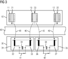
- Figure 3 shows in a third schematic sketch a further plan view of the exemplary embodiment of the sensor device according to the invention.
- the representation corresponds to the transmitter side of those of Figure 2 .
- the electrical circuit is now indicated to the effect that the receiving coils 32 and 33 of the receiving device 31 are connected in series in opposite directions in accordance with the indicated winding direction and, together with a capacitor 34, form a receiving resonant circuit.
- a receiving resonant circuit is also formed by the receiving coils 36 and 37 of the receiving device 35 together with a capacitor 38.
- the corresponding receive or signal voltages are in Figure 3 identified by the reference numerals 41 and 42, respectively.
- the structure of the sensor device with the further transmitter coil 13 arranged between the transmitter coils 11, 12 also means that in all operational situations there is sufficient signal overlap between the receiving or signal voltages 41 and 42 of the receiving devices 31 and 35, which is particularly relevant for detecting the direction of travel results. The reason for this is that even when a wheel is in the middle position above the sensor device, a voltage is generated or induced at least in the reception coils 33 and 36 due to the further transmission coil 13.
- the sensor device according to the invention has the particular advantage that externally induced interferences are largely suppressed, since these generally affect both receiving coils 32 and 33 or 36 and 37 of the respective receiving device 31 or 35 equally. This results, in particular for the preferred case in which all receiver coils 32, 33, 36 and 37 have the same distance and the same orientation from the running rail 60, a high level of immunity to interference, in particular with regard to magnetic fields caused by rail currents.
- the arrangement of the at least one further transmitter coil 13 between the transmitter coils 11 and 12, as already explained, advantageously leads to an increase in the signal overlap of the receiving devices 31 and 35 Receiving devices 31 and 35.
- both interference field-compensating receiving coils 32 and 33 or 36 and 37 of the receiving devices 31 and 35 which can also be referred to as receiving channels, contribute to the received or useful signal. As a result, this leads to an increase in the reception voltage and thus to an increased detection sensitivity of the sensor device.
Landscapes
- Engineering & Computer Science (AREA)
- Automation & Control Theory (AREA)
- Mechanical Engineering (AREA)
- Train Traffic Observation, Control, And Security (AREA)
- Investigating Or Analyzing Materials By The Use Of Magnetic Means (AREA)
Priority Applications (1)
| Application Number | Priority Date | Filing Date | Title |
|---|---|---|---|
| PL16726083T PL3294608T3 (pl) | 2015-06-30 | 2016-05-30 | Urządzenie czujnikowe do wykrywania koła poruszającego się wzdłuż szyny jezdnej |
Applications Claiming Priority (2)
| Application Number | Priority Date | Filing Date | Title |
|---|---|---|---|
| DE102015212120.8A DE102015212120A1 (de) | 2015-06-30 | 2015-06-30 | Sensoreinrichtung zum Detektieren eines sich entlang einer Fahrschiene bewegenden Rades |
| PCT/EP2016/062141 WO2017001128A1 (de) | 2015-06-30 | 2016-05-30 | Sensoreinrichtung zum detektieren eines sich entlang einer fahrschiene bewegenden rades |
Publications (2)
| Publication Number | Publication Date |
|---|---|
| EP3294608A1 EP3294608A1 (de) | 2018-03-21 |
| EP3294608B1 true EP3294608B1 (de) | 2021-11-17 |
Family
ID=56092917
Family Applications (1)
| Application Number | Title | Priority Date | Filing Date |
|---|---|---|---|
| EP16726083.5A Active EP3294608B1 (de) | 2015-06-30 | 2016-05-30 | Sensoreinrichtung zum detektieren eines sich entlang einer fahrschiene bewegenden rades |
Country Status (6)
| Country | Link |
|---|---|
| EP (1) | EP3294608B1 (pl) |
| AU (1) | AU2016287693B2 (pl) |
| DE (1) | DE102015212120A1 (pl) |
| ES (1) | ES2905590T3 (pl) |
| PL (1) | PL3294608T3 (pl) |
| WO (1) | WO2017001128A1 (pl) |
Families Citing this family (2)
| Publication number | Priority date | Publication date | Assignee | Title |
|---|---|---|---|---|
| DE102023204900A1 (de) * | 2023-05-25 | 2024-11-28 | Siemens Mobility GmbH | Induktiv wirkende Radsensoranordnung |
| DE102024201685A1 (de) * | 2024-02-23 | 2025-08-28 | Siemens Mobility GmbH | Sensoranordnung zur Montage an einer Fahrschiene und Verfahren zum Detektieren von auf einer Fahrschiene vorbeirollenden Rädern |
Family Cites Families (5)
| Publication number | Priority date | Publication date | Assignee | Title |
|---|---|---|---|---|
| DE1605427C3 (de) * | 1967-07-20 | 1974-04-25 | Siemens Ag, 1000 Berlin Und 8000 Muenchen | Schaltungsanordnung zum Erzeugen und Übertragen von Achszählimpulsen in Achszählanlagen |
| US3721821A (en) * | 1970-12-14 | 1973-03-20 | Abex Corp | Railway wheel sensor |
| DD118034A1 (pl) * | 1975-03-19 | 1976-02-12 | ||
| DE10350733B4 (de) * | 2003-10-20 | 2006-04-27 | Werner Turck Gmbh & Co. Kg | Induktiver Näherungsschalter mit Differenzspulenanordnung |
| PL199810B1 (pl) | 2003-11-12 | 2008-11-28 | Bombardier Transp Zwus Polska | Zespolona dwukanałowa głowica czujnika koła pojazdu szynowego |
-
2015
- 2015-06-30 DE DE102015212120.8A patent/DE102015212120A1/de not_active Withdrawn
-
2016
- 2016-05-30 PL PL16726083T patent/PL3294608T3/pl unknown
- 2016-05-30 AU AU2016287693A patent/AU2016287693B2/en active Active
- 2016-05-30 EP EP16726083.5A patent/EP3294608B1/de active Active
- 2016-05-30 ES ES16726083T patent/ES2905590T3/es active Active
- 2016-05-30 WO PCT/EP2016/062141 patent/WO2017001128A1/de not_active Ceased
Also Published As
| Publication number | Publication date |
|---|---|
| DE102015212120A1 (de) | 2017-01-05 |
| AU2016287693B2 (en) | 2019-01-31 |
| EP3294608A1 (de) | 2018-03-21 |
| WO2017001128A1 (de) | 2017-01-05 |
| ES2905590T3 (es) | 2022-04-11 |
| AU2016287693A1 (en) | 2017-12-21 |
| PL3294608T3 (pl) | 2022-03-14 |
Similar Documents
| Publication | Publication Date | Title |
|---|---|---|
| EP2496459B1 (de) | Radsensor | |
| EP3107791B1 (de) | Sensoreinrichtung zum erfassen einer magnetfeldänderung sowie anlage des spurgebundenen verkehrs mit zumindest einer solchen sensoreinrichtung | |
| DE102010027017A1 (de) | Induktive Sensoreinrichtung sowie induktiver Näherungssensor mit einer induktiven Sensoreinrichtung | |
| EP2349810B1 (de) | Radsensor | |
| DE1780040C2 (de) | Zuganwesenheits-Signalsystem | |
| EP3294608B1 (de) | Sensoreinrichtung zum detektieren eines sich entlang einer fahrschiene bewegenden rades | |
| EP3475142A1 (de) | Sendereinrichtung, sensoreinrichtung und verfahren zum erfassen einer magnetfeldänderung | |
| DE2951124C2 (de) | Elektrischer Trennstoß für mit Wechselstrom gespeiste Gleisstromkreise in Eisenbahnanlagen | |
| EP1288098B1 (de) | Radsensor und Anordnung | |
| EP2797802B1 (de) | Sensoreinrichtung zum detektieren eines sich entlang einer fahrschiene bewegenden rades | |
| EP2146887A1 (de) | Radsensor | |
| DE2335280C2 (de) | Fahrzeugbetätigte Einrichtung | |
| EP4144612A1 (de) | Sensoreinrichtung, anordnung und verfahren zum erfassen einer änderung eines magnetfeldes | |
| EP4327137B1 (de) | Sensoreinrichtung, schienenfahrzeug und sensoranordnung | |
| EP4467416A1 (de) | Induktiv wirkende radsensoranordnung | |
| DE9420736U1 (de) | Einrichtung zum Vermeiden von Fehlzählungen bei der Achszählung im Eisenbahnwesen | |
| DE102012015200A1 (de) | Induktiver Näherungsschalter | |
| EP3569466B1 (de) | Sensor zum erfassen von metallteilen, sowie verfahren zum abschwächen eines magnetischen feldes | |
| DE1909423B2 (de) | Schaltungsanordnung für mit Wechselstrom gespeiste Gleisstromkreise in Weichen- und Kreuzungsbereichen von Eisenbahnanlagen | |
| DE3720576A1 (de) | Einrichtung an einem elektronischen doppelschienenkontakt | |
| EP4277824A2 (de) | Verfahren und anordnung zum überwachen von gleisabschnitten | |
| DE1206008B (de) | Schaltungsanordnung fuer mit Wechselstrom gespeiste Gleisstromkreise fuer Eisenbahnsicherungsanlagen | |
| DE1190492B (de) | Selbsttaetiger Streckenblock mit nichtisolierten Gleisstromkreisen |
Legal Events
| Date | Code | Title | Description |
|---|---|---|---|
| STAA | Information on the status of an ep patent application or granted ep patent |
Free format text: STATUS: THE INTERNATIONAL PUBLICATION HAS BEEN MADE |
|
| PUAI | Public reference made under article 153(3) epc to a published international application that has entered the european phase |
Free format text: ORIGINAL CODE: 0009012 |
|
| STAA | Information on the status of an ep patent application or granted ep patent |
Free format text: STATUS: REQUEST FOR EXAMINATION WAS MADE |
|
| 17P | Request for examination filed |
Effective date: 20171213 |
|
| AK | Designated contracting states |
Kind code of ref document: A1 Designated state(s): AL AT BE BG CH CY CZ DE DK EE ES FI FR GB GR HR HU IE IS IT LI LT LU LV MC MK MT NL NO PL PT RO RS SE SI SK SM TR |
|
| AX | Request for extension of the european patent |
Extension state: BA ME |
|
| DAV | Request for validation of the european patent (deleted) | ||
| DAX | Request for extension of the european patent (deleted) | ||
| RAP1 | Party data changed (applicant data changed or rights of an application transferred) |
Owner name: SIEMENS MOBILITY GMBH |
|
| GRAP | Despatch of communication of intention to grant a patent |
Free format text: ORIGINAL CODE: EPIDOSNIGR1 |
|
| STAA | Information on the status of an ep patent application or granted ep patent |
Free format text: STATUS: GRANT OF PATENT IS INTENDED |
|
| INTG | Intention to grant announced |
Effective date: 20210615 |
|
| GRAS | Grant fee paid |
Free format text: ORIGINAL CODE: EPIDOSNIGR3 |
|
| GRAA | (expected) grant |
Free format text: ORIGINAL CODE: 0009210 |
|
| STAA | Information on the status of an ep patent application or granted ep patent |
Free format text: STATUS: THE PATENT HAS BEEN GRANTED |
|
| AK | Designated contracting states |
Kind code of ref document: B1 Designated state(s): AL AT BE BG CH CY CZ DE DK EE ES FI FR GB GR HR HU IE IS IT LI LT LU LV MC MK MT NL NO PL PT RO RS SE SI SK SM TR |
|
| REG | Reference to a national code |
Ref country code: GB Ref legal event code: FG4D Free format text: NOT ENGLISH |
|
| REG | Reference to a national code |
Ref country code: DE Ref legal event code: R096 Ref document number: 502016014160 Country of ref document: DE |
|
| REG | Reference to a national code |
Ref country code: IE Ref legal event code: FG4D Free format text: LANGUAGE OF EP DOCUMENT: GERMAN |
|
| REG | Reference to a national code |
Ref country code: AT Ref legal event code: REF Ref document number: 1447820 Country of ref document: AT Kind code of ref document: T Effective date: 20211215 |
|
| REG | Reference to a national code |
Ref country code: NL Ref legal event code: FP |
|
| REG | Reference to a national code |
Ref country code: LT Ref legal event code: MG9D |
|
| REG | Reference to a national code |
Ref country code: ES Ref legal event code: FG2A Ref document number: 2905590 Country of ref document: ES Kind code of ref document: T3 Effective date: 20220411 |
|
| PG25 | Lapsed in a contracting state [announced via postgrant information from national office to epo] |
Ref country code: RS Free format text: LAPSE BECAUSE OF FAILURE TO SUBMIT A TRANSLATION OF THE DESCRIPTION OR TO PAY THE FEE WITHIN THE PRESCRIBED TIME-LIMIT Effective date: 20211117 Ref country code: LT Free format text: LAPSE BECAUSE OF FAILURE TO SUBMIT A TRANSLATION OF THE DESCRIPTION OR TO PAY THE FEE WITHIN THE PRESCRIBED TIME-LIMIT Effective date: 20211117 Ref country code: FI Free format text: LAPSE BECAUSE OF FAILURE TO SUBMIT A TRANSLATION OF THE DESCRIPTION OR TO PAY THE FEE WITHIN THE PRESCRIBED TIME-LIMIT Effective date: 20211117 Ref country code: BG Free format text: LAPSE BECAUSE OF FAILURE TO SUBMIT A TRANSLATION OF THE DESCRIPTION OR TO PAY THE FEE WITHIN THE PRESCRIBED TIME-LIMIT Effective date: 20220217 |
|
| PG25 | Lapsed in a contracting state [announced via postgrant information from national office to epo] |
Ref country code: IS Free format text: LAPSE BECAUSE OF FAILURE TO SUBMIT A TRANSLATION OF THE DESCRIPTION OR TO PAY THE FEE WITHIN THE PRESCRIBED TIME-LIMIT Effective date: 20220317 Ref country code: SE Free format text: LAPSE BECAUSE OF FAILURE TO SUBMIT A TRANSLATION OF THE DESCRIPTION OR TO PAY THE FEE WITHIN THE PRESCRIBED TIME-LIMIT Effective date: 20211117 Ref country code: PT Free format text: LAPSE BECAUSE OF FAILURE TO SUBMIT A TRANSLATION OF THE DESCRIPTION OR TO PAY THE FEE WITHIN THE PRESCRIBED TIME-LIMIT Effective date: 20220317 Ref country code: NO Free format text: LAPSE BECAUSE OF FAILURE TO SUBMIT A TRANSLATION OF THE DESCRIPTION OR TO PAY THE FEE WITHIN THE PRESCRIBED TIME-LIMIT Effective date: 20220217 Ref country code: LV Free format text: LAPSE BECAUSE OF FAILURE TO SUBMIT A TRANSLATION OF THE DESCRIPTION OR TO PAY THE FEE WITHIN THE PRESCRIBED TIME-LIMIT Effective date: 20211117 Ref country code: HR Free format text: LAPSE BECAUSE OF FAILURE TO SUBMIT A TRANSLATION OF THE DESCRIPTION OR TO PAY THE FEE WITHIN THE PRESCRIBED TIME-LIMIT Effective date: 20211117 Ref country code: GR Free format text: LAPSE BECAUSE OF FAILURE TO SUBMIT A TRANSLATION OF THE DESCRIPTION OR TO PAY THE FEE WITHIN THE PRESCRIBED TIME-LIMIT Effective date: 20220218 |
|
| PG25 | Lapsed in a contracting state [announced via postgrant information from national office to epo] |
Ref country code: SM Free format text: LAPSE BECAUSE OF FAILURE TO SUBMIT A TRANSLATION OF THE DESCRIPTION OR TO PAY THE FEE WITHIN THE PRESCRIBED TIME-LIMIT Effective date: 20211117 Ref country code: SK Free format text: LAPSE BECAUSE OF FAILURE TO SUBMIT A TRANSLATION OF THE DESCRIPTION OR TO PAY THE FEE WITHIN THE PRESCRIBED TIME-LIMIT Effective date: 20211117 Ref country code: RO Free format text: LAPSE BECAUSE OF FAILURE TO SUBMIT A TRANSLATION OF THE DESCRIPTION OR TO PAY THE FEE WITHIN THE PRESCRIBED TIME-LIMIT Effective date: 20211117 Ref country code: EE Free format text: LAPSE BECAUSE OF FAILURE TO SUBMIT A TRANSLATION OF THE DESCRIPTION OR TO PAY THE FEE WITHIN THE PRESCRIBED TIME-LIMIT Effective date: 20211117 Ref country code: DK Free format text: LAPSE BECAUSE OF FAILURE TO SUBMIT A TRANSLATION OF THE DESCRIPTION OR TO PAY THE FEE WITHIN THE PRESCRIBED TIME-LIMIT Effective date: 20211117 Ref country code: CZ Free format text: LAPSE BECAUSE OF FAILURE TO SUBMIT A TRANSLATION OF THE DESCRIPTION OR TO PAY THE FEE WITHIN THE PRESCRIBED TIME-LIMIT Effective date: 20211117 |
|
| REG | Reference to a national code |
Ref country code: DE Ref legal event code: R097 Ref document number: 502016014160 Country of ref document: DE |
|
| PLBE | No opposition filed within time limit |
Free format text: ORIGINAL CODE: 0009261 |
|
| STAA | Information on the status of an ep patent application or granted ep patent |
Free format text: STATUS: NO OPPOSITION FILED WITHIN TIME LIMIT |
|
| 26N | No opposition filed |
Effective date: 20220818 |
|
| PG25 | Lapsed in a contracting state [announced via postgrant information from national office to epo] |
Ref country code: AL Free format text: LAPSE BECAUSE OF FAILURE TO SUBMIT A TRANSLATION OF THE DESCRIPTION OR TO PAY THE FEE WITHIN THE PRESCRIBED TIME-LIMIT Effective date: 20211117 |
|
| PG25 | Lapsed in a contracting state [announced via postgrant information from national office to epo] |
Ref country code: SI Free format text: LAPSE BECAUSE OF FAILURE TO SUBMIT A TRANSLATION OF THE DESCRIPTION OR TO PAY THE FEE WITHIN THE PRESCRIBED TIME-LIMIT Effective date: 20211117 |
|
| PG25 | Lapsed in a contracting state [announced via postgrant information from national office to epo] |
Ref country code: MC Free format text: LAPSE BECAUSE OF FAILURE TO SUBMIT A TRANSLATION OF THE DESCRIPTION OR TO PAY THE FEE WITHIN THE PRESCRIBED TIME-LIMIT Effective date: 20211117 Ref country code: LU Free format text: LAPSE BECAUSE OF NON-PAYMENT OF DUE FEES Effective date: 20220530 |
|
| PG25 | Lapsed in a contracting state [announced via postgrant information from national office to epo] |
Ref country code: IE Free format text: LAPSE BECAUSE OF NON-PAYMENT OF DUE FEES Effective date: 20220530 Ref country code: FR Free format text: LAPSE BECAUSE OF NON-PAYMENT OF DUE FEES Effective date: 20220531 |
|
| PG25 | Lapsed in a contracting state [announced via postgrant information from national office to epo] |
Ref country code: IT Free format text: LAPSE BECAUSE OF FAILURE TO SUBMIT A TRANSLATION OF THE DESCRIPTION OR TO PAY THE FEE WITHIN THE PRESCRIBED TIME-LIMIT Effective date: 20211117 |
|
| PG25 | Lapsed in a contracting state [announced via postgrant information from national office to epo] |
Ref country code: HU Free format text: LAPSE BECAUSE OF FAILURE TO SUBMIT A TRANSLATION OF THE DESCRIPTION OR TO PAY THE FEE WITHIN THE PRESCRIBED TIME-LIMIT; INVALID AB INITIO Effective date: 20160530 |
|
| PG25 | Lapsed in a contracting state [announced via postgrant information from national office to epo] |
Ref country code: MK Free format text: LAPSE BECAUSE OF FAILURE TO SUBMIT A TRANSLATION OF THE DESCRIPTION OR TO PAY THE FEE WITHIN THE PRESCRIBED TIME-LIMIT Effective date: 20211117 Ref country code: CY Free format text: LAPSE BECAUSE OF FAILURE TO SUBMIT A TRANSLATION OF THE DESCRIPTION OR TO PAY THE FEE WITHIN THE PRESCRIBED TIME-LIMIT Effective date: 20211117 |
|
| PG25 | Lapsed in a contracting state [announced via postgrant information from national office to epo] |
Ref country code: MT Free format text: LAPSE BECAUSE OF FAILURE TO SUBMIT A TRANSLATION OF THE DESCRIPTION OR TO PAY THE FEE WITHIN THE PRESCRIBED TIME-LIMIT Effective date: 20211117 |
|
| PGFP | Annual fee paid to national office [announced via postgrant information from national office to epo] |
Ref country code: NL Payment date: 20250508 Year of fee payment: 10 |
|
| PGFP | Annual fee paid to national office [announced via postgrant information from national office to epo] |
Ref country code: PL Payment date: 20250523 Year of fee payment: 10 |
|
| PGFP | Annual fee paid to national office [announced via postgrant information from national office to epo] |
Ref country code: GB Payment date: 20250610 Year of fee payment: 10 |
|
| PGFP | Annual fee paid to national office [announced via postgrant information from national office to epo] |
Ref country code: BE Payment date: 20250521 Year of fee payment: 10 |
|
| PGFP | Annual fee paid to national office [announced via postgrant information from national office to epo] |
Ref country code: AT Payment date: 20250408 Year of fee payment: 10 |
|
| REG | Reference to a national code |
Ref country code: DE Ref legal event code: R081 Ref document number: 502016014160 Country of ref document: DE Owner name: SIEMENS MOBILITY GMBH, DE Free format text: FORMER OWNER: SIEMENS MOBILITY GMBH, 81739 MUENCHEN, DE |
|
| PGFP | Annual fee paid to national office [announced via postgrant information from national office to epo] |
Ref country code: ES Payment date: 20250825 Year of fee payment: 10 |
|
| PGFP | Annual fee paid to national office [announced via postgrant information from national office to epo] |
Ref country code: DE Payment date: 20250718 Year of fee payment: 10 |
|
| PGFP | Annual fee paid to national office [announced via postgrant information from national office to epo] |
Ref country code: CH Payment date: 20250812 Year of fee payment: 10 |
|
| PG25 | Lapsed in a contracting state [announced via postgrant information from national office to epo] |
Ref country code: TR Free format text: LAPSE BECAUSE OF FAILURE TO SUBMIT A TRANSLATION OF THE DESCRIPTION OR TO PAY THE FEE WITHIN THE PRESCRIBED TIME-LIMIT Effective date: 20211117 |