EP3293617B1 - Capteur tactile, appareil à détection tactile et procédé de détection, et dispositif à commande tactile - Google Patents
Capteur tactile, appareil à détection tactile et procédé de détection, et dispositif à commande tactile Download PDFInfo
- Publication number
- EP3293617B1 EP3293617B1 EP16891891.0A EP16891891A EP3293617B1 EP 3293617 B1 EP3293617 B1 EP 3293617B1 EP 16891891 A EP16891891 A EP 16891891A EP 3293617 B1 EP3293617 B1 EP 3293617B1
- Authority
- EP
- European Patent Office
- Prior art keywords
- electrode layer
- capacitance value
- touch
- self
- layer
- Prior art date
- Legal status (The legal status is an assumption and is not a legal conclusion. Google has not performed a legal analysis and makes no representation as to the accuracy of the status listed.)
- Active
Links
Images


Classifications
-
- G—PHYSICS
- G06—COMPUTING; CALCULATING OR COUNTING
- G06F—ELECTRIC DIGITAL DATA PROCESSING
- G06F3/00—Input arrangements for transferring data to be processed into a form capable of being handled by the computer; Output arrangements for transferring data from processing unit to output unit, e.g. interface arrangements
- G06F3/01—Input arrangements or combined input and output arrangements for interaction between user and computer
- G06F3/03—Arrangements for converting the position or the displacement of a member into a coded form
- G06F3/041—Digitisers, e.g. for touch screens or touch pads, characterised by the transducing means
- G06F3/044—Digitisers, e.g. for touch screens or touch pads, characterised by the transducing means by capacitive means
- G06F3/0445—Digitisers, e.g. for touch screens or touch pads, characterised by the transducing means by capacitive means using two or more layers of sensing electrodes, e.g. using two layers of electrodes separated by a dielectric layer
-
- G—PHYSICS
- G06—COMPUTING; CALCULATING OR COUNTING
- G06F—ELECTRIC DIGITAL DATA PROCESSING
- G06F3/00—Input arrangements for transferring data to be processed into a form capable of being handled by the computer; Output arrangements for transferring data from processing unit to output unit, e.g. interface arrangements
- G06F3/01—Input arrangements or combined input and output arrangements for interaction between user and computer
- G06F3/03—Arrangements for converting the position or the displacement of a member into a coded form
- G06F3/041—Digitisers, e.g. for touch screens or touch pads, characterised by the transducing means
- G06F3/0414—Digitisers, e.g. for touch screens or touch pads, characterised by the transducing means using force sensing means to determine a position
-
- G—PHYSICS
- G06—COMPUTING; CALCULATING OR COUNTING
- G06F—ELECTRIC DIGITAL DATA PROCESSING
- G06F3/00—Input arrangements for transferring data to be processed into a form capable of being handled by the computer; Output arrangements for transferring data from processing unit to output unit, e.g. interface arrangements
- G06F3/01—Input arrangements or combined input and output arrangements for interaction between user and computer
- G06F3/03—Arrangements for converting the position or the displacement of a member into a coded form
- G06F3/041—Digitisers, e.g. for touch screens or touch pads, characterised by the transducing means
- G06F3/0412—Digitisers structurally integrated in a display
-
- G—PHYSICS
- G06—COMPUTING; CALCULATING OR COUNTING
- G06F—ELECTRIC DIGITAL DATA PROCESSING
- G06F3/00—Input arrangements for transferring data to be processed into a form capable of being handled by the computer; Output arrangements for transferring data from processing unit to output unit, e.g. interface arrangements
- G06F3/01—Input arrangements or combined input and output arrangements for interaction between user and computer
- G06F3/03—Arrangements for converting the position or the displacement of a member into a coded form
- G06F3/041—Digitisers, e.g. for touch screens or touch pads, characterised by the transducing means
- G06F3/0416—Control or interface arrangements specially adapted for digitisers
- G06F3/04166—Details of scanning methods, e.g. sampling time, grouping of sub areas or time sharing with display driving
-
- G—PHYSICS
- G06—COMPUTING; CALCULATING OR COUNTING
- G06F—ELECTRIC DIGITAL DATA PROCESSING
- G06F3/00—Input arrangements for transferring data to be processed into a form capable of being handled by the computer; Output arrangements for transferring data from processing unit to output unit, e.g. interface arrangements
- G06F3/01—Input arrangements or combined input and output arrangements for interaction between user and computer
- G06F3/03—Arrangements for converting the position or the displacement of a member into a coded form
- G06F3/041—Digitisers, e.g. for touch screens or touch pads, characterised by the transducing means
- G06F3/044—Digitisers, e.g. for touch screens or touch pads, characterised by the transducing means by capacitive means
- G06F3/0446—Digitisers, e.g. for touch screens or touch pads, characterised by the transducing means by capacitive means using a grid-like structure of electrodes in at least two directions, e.g. using row and column electrodes
-
- G—PHYSICS
- G06—COMPUTING; CALCULATING OR COUNTING
- G06F—ELECTRIC DIGITAL DATA PROCESSING
- G06F3/00—Input arrangements for transferring data to be processed into a form capable of being handled by the computer; Output arrangements for transferring data from processing unit to output unit, e.g. interface arrangements
- G06F3/01—Input arrangements or combined input and output arrangements for interaction between user and computer
- G06F3/03—Arrangements for converting the position or the displacement of a member into a coded form
- G06F3/041—Digitisers, e.g. for touch screens or touch pads, characterised by the transducing means
- G06F3/044—Digitisers, e.g. for touch screens or touch pads, characterised by the transducing means by capacitive means
- G06F3/0447—Position sensing using the local deformation of sensor cells
-
- G—PHYSICS
- G06—COMPUTING; CALCULATING OR COUNTING
- G06F—ELECTRIC DIGITAL DATA PROCESSING
- G06F3/00—Input arrangements for transferring data to be processed into a form capable of being handled by the computer; Output arrangements for transferring data from processing unit to output unit, e.g. interface arrangements
- G06F3/01—Input arrangements or combined input and output arrangements for interaction between user and computer
- G06F3/03—Arrangements for converting the position or the displacement of a member into a coded form
- G06F3/041—Digitisers, e.g. for touch screens or touch pads, characterised by the transducing means
- G06F3/044—Digitisers, e.g. for touch screens or touch pads, characterised by the transducing means by capacitive means
- G06F3/0448—Details of the electrode shape, e.g. for enhancing the detection of touches, for generating specific electric field shapes, for enhancing display quality
Definitions
- the present disclosure relates to the technical field of touch control technology, and in particular, a touch sensor, a touch detection device and detection method and a touch control apparatus.
- touch control technology Due to its convenience and intuition for input, touch control technology has been widely used in a variety of electronic apparatus, such as a touch panel of a laptop, touch screens of a tablet computer and a smart phone, etc..
- the principle of the touch control technology is to identify a specific touch position of the touch operation by using a touch position detection mechanism, and make a response to the touch operation on the touch position.
- a pressure detection is integrated with the touch control, it is possible to further identify touch pressure information (such as pressure value, etc.) when a specific touch location is identified. And, some applications based on the touch pressure will bring a better experience to users, especially for a smart phone with increased application scenes, if a function of the touch pressure detection is supported, the smart phone will be more competitive in the market. As a result, the touch detection technology capable of detecting a touch pressure is attracting more and more attention from users and manufacturers of touch control apparatuses.
- the touch pressure detection on a touch control apparatus is mainly achieved by additionally adding a pressure detection device to the touch control apparatus with a function of touch position detection.
- a pressure detection device for example, a capacitance pressure sensor and a demodulation circuit corresponding thereto are added between a screen and an middle frame of the touch control apparatus, or a pressure sensitive material is adhered around the protective glass and the border of the touch control apparatus.
- WO 2016/033219 A1 discloses a force-sensitive structure which includes a first substrate and a second substrate which are separated by a gap that may be substantially filled with a compliant medium. Upper electrodes and lower electrodes are disposed on the first substrate and the second substrate correspondingly to detect the location and magnitude of the force of a touch.
- a separate touch sensor layer is disclosed which includes a self-capacitive or mutually-capacitive sensor that is configured to detect the location of a touch on the surface of the cover glass. The detected location may be used in order to scan only the electrodes close to the location of the touch for force sensing.
- US 2015/ 130742 A1 discloses a force detecting method that operates by comparing the change from the signal without a touch to the signal with a touch.
- a baseline capacitance map related to a first capacitance is generated by applying a drive voltage to one or two groups of electrodes.
- the measured capacitances are obtained by applying a drive voltage in the same manner as the drive voltage that is applied when no touch is performed. The measured capacitance is compared with the baseline capacitance at the corresponding position to determine whether there is a press.
- the technical problem to be solved by embodiments of the present invention is to realize highly sensitive touch pressure detection by using a conventional touch control position detection structure without increasing the thickness of the touch control apparatus, so as to enhance user experiences.
- An embodiment of the present invention also provides a touch detection device according to independent claim 1.
- An Embodiment of the present invention also provides a touch control apparatus having a built-in touch detection device as described above.
- Embodiments of the present invention also provide a detection method according to independent claim 10.
- the pressure of the user's touch operation can be transferred to the third electrode layer through the compressible layer, the capacitance value between the second electrode layer and the third electrode layer is changed, therefore, when the touch pressure is detected, the pressure information of the user's touch operation can be calculated from the change in the capacitance value.
- all electrode layers can completely multiplex some parts having an electrode layer which are originally present in the touch control apparatus, it means that highly sensitive touch pressure detection is realized without increasing the thickness and cost of the touch control apparatus, so as to enhance the user experience.
- the touch sensor for realizing a touch position detection generally includes a first electrode layer and a second electrode layer, and a capacitor structure is formed between the two electrode layers, thus realizing mutual-capacitance detection.
- the touch sensor also includes a third electrode layer separated from the second electrode layer by a compressible layer. The pressure of a user's touch operation can be transferred to the third electrode layer through the compressible layer, and then the capacitance value between the second electrode layer and the third electrode layer is changed accordingly. Thus, when the detection of the touch pressure is performed, the pressure information of the user's touch operation can be calculated from the change in the capacitance value.
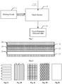
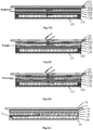
- the touch detection device includes a driving circuit 1, a touch sensor 2 and a touch pressure detection unit 3, as shown in Fig. 1 .
- the touch detection device may be built in an apparatus which requires having a touch control and pressure detection function, such as a smart phone, a tablet computer, a computer touch panel, etc.
- Fig. 2 shows the structure of the above touch sensor 2
- the touch sensor 2 comprises a first electrode layer 21, a second electrode layer 22 and a third electrode layer 23, and a rigid insulating layer 24 is provided between the first electrode layer 21 and the second electrode layer 22 and is configured to separate the first electrode layer 21 from the second electrode layer 22 with a fixed distance
- a compressible layer 25 is provided between the second electrode layer 22 and the third electrode layer 23 and has a certain compressibility to sense deformation caused by the user's touch pressure.
- a protective layer 26 may be provided on the surface of the first electrode layer 21 to protect the first electrode layer 21, thereby preventing the first electrode layer 21 from being damaged by scratches, impacts, etc.
- the first electrode layer 21, the second electrode layer 22, and the rigid insulating layer 24 constitute a touch sensing component for detecting the touch position , for example, and when the touch position is detected, the touch sensing component may be achieved by the first electrode layer 21 together with the second electrode layer 22 (e.g., a mutual-capacitance touch sensor); of course, the touch sensing component may also be achieved by the first electrode layer 21 alone (e.g., a self-capacitance touch sensor).
- the electrode patterns on the first electrode layer 21 and the second electrode layer 22 may be formed in a stripe shape, a vertical bar shape, a matrix shape, a wavy stripes, etc., as shown in Figs. 3A to 3D .
- the second electrode layer 22 may be designed without any electrode pattern, and a whole block of electrode as shown in Fig. 3E may be used as the second electrode layer 22.
- the whole block of electrode as shown in Fig. 3E may also be used as the third electrode layer 23, or some simple pattern may be designed on the third electrode layer 23, as long as the second electrode layer 22 and the third electrode layer 23 can form a capacitor structure.
- the compressible layer 25 is deformed by the touch pressure and thus the distance between the first electrode layer 22 and the second electrode layer 23 is changed, therefore, the capacitance value of the capacitor structure formed by the second electrode layer 22 and the third electrode layer 23 may vary with the change of the distance between the second electrode layer 22 and the third electrode layer 23.
- the driving circuit 1 is configured to drive the first electrode layer 21, the second electrode layer 22, and the third electrode layer 23 in the touch sensor 2.
- the touch pressure detection unit 3 is configured to calculate the pressure information of the user's touch operation from the detected change in the capacitance value of the capacitor structure.
- the 'capacitance value of the capacitor structure' in the present disclosure refers to the capacitance value of the capacitor structure formed by the second electrode layer 22 and the third electrode layer 23.
- the touch pressure detection unit 3 may calculate the pressure information of the user's touch operation on the touch sensor 2 from the change in the capacitance value of the capacitor structure detected before and after the touch operation.
- the detection of the touch position may be determined by the change in mutual-capacitance between the first electrode layer 21 and the second electrode layer 22 before and after the touch operation (mutual-capacitance detection principle), or may be determined only by the detection of the first electrode layer 21 (self-capacitance detection principle).
- the first electrode layer 21 is used as the detection electrode of the whole touch detection device, therefore, it is necessary to detect the first electrode layer 21 to obtain the capacitance value of the above capacitor structure.
- the detection result may also include the capacitance value between the first electrode layer 21 and the second electrode layer 22, and when a touch operation is performed, the detection result may even include a capacitance value between the touch finger and the first electrode layer 21. Therefore, in order to calculate the change in the capacitance value of the capacitor structure, it is necessary to remove unnecessary portions included in the detection result before and after the touch operation.
- the driving signal output from the driving circuit 1 to the second electrode layer 22 is at a fixed level, or the second electrode layer 22 is in a suspended state, or the second electrode layer 22 is input with some signal; for example, the driving signal outputted from the driving circuit 1 to the third electrode layer is at a fixed level (which may be a fixed level of zero potential the same as the ground or other potential) or the third electrode layer is in a suspended state, or the third electrode layer is input with some signal.
- the detection method of the touch detection device as described above includes the following steps.
- a first driving step when no touch operation is performed, the first electrode layer, the second electrode layer, and the third electrode layer is driven by a first set of driving signals.
- a first capacitance value detection step when no touch operation is performed, the capacitor structure is detected to obtain a first capacitance value.
- a second driving step when a touch operation is performed, the first electrode layer, the second electrode layer and the third electrode layer is driven with a second set of driving signals.
- a second capacitance value detection step when a touch operation is performed, the capacitor structure is detected to obtain a second capacitance value.
- a touch pressure calculation step the pressure information of the user's touch operation is calculated from the difference between the first capacitance value and the second capacitance value.
- Embodiments of the present invention will provide two detection modes to describe the principle of touch pressure detection.
- the first set of driving signals includes a first driving signal and a first fixed level signal for the self-capacitance detection of the first electrode layer;
- the second set of driving signals includes a second driving signal and a second fixed level signal for the self-capacitance detection of the first electrode layer.
- the first driving signal and the second driving signal may be a sine wave signal, a square wave signal, etc.
- the first fixed level signal and the second fixed level signal may be signals at any fixed level including but not limited to 0V.
- a certain electrode layer being in a "suspended state” means that all the electrodes in the electrode layer are in the suspended state, or means that some electrodes in the electrode layer are in the suspended state.
- a touch pressure detection method of the touch detecting device includes the following steps:
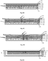
- a first driving step S401 when no touch operation is performed, the first electrode layer 21 is constantly driven by the driving circuit 1 with a first driving signal in the first set of driving signals, the second electrode layer 22 is firstly input with a first fixed level signal V and then is set to be in a suspended state, and the third electrode layer 23 is grounded;
- a first capacitance value detection step 402 the touch pressure detection unit 3 detects a self-capacitance value C11 of the first electrode layer 21 when the second electrode layer 22 is input with the first fixed level signal V, and detects a self-capacitance value C15 of the first electrode layer 21 when the second electrode layer 22 is set to be in the suspended state and the third electrode layer 23 is grounded; then a first capacitance value C12 is calculated from the self-capacitance value C11 and the self-capacitance value C15.
- the self-capacitance value C11 is the capacitance value between the first electrode layer 21 driven by the first driving signal and the second electrode layer 22 input with the first fixed level signal V, and the detection is shown in Fig. 5A .
- the capacitance value C15 is a series value of the self-capacitance value C11 and the first capacitance value C12
- a second driving step S403 the first electrode layer 21 is constantly driven by the driving circuit 1 with a second driving signal, the second electrode layer 22 is firstly input with a second fixed level signal V and then is set to be in a suspended state, and the third electrode layer 23 is grounded.
- a second capacitance value detection step S404 when a touch operation is performed, the touch detection unit 3 detects a self-capacitance value C16 of the first electrode layer 21 when the second electrode layer 22 is input with the second fixed level signal V, and detects a self-capacitance value C18 of the first electrode layer 21 when the second electrode layer 22 is set to be in the suspended state and the third electrode layer 23 is grounded.
- a capacitance value C13 between a touch finger and the first electrode layer 21 is calculated from the self-capacitance value C11 and the self-capacitance value C16; next, a series value C19 of the self-capacitance value C11 and the second capacitance value is calculated from the capacitance value C13 and the self-capacitance value C18; then, the second capacitance value C14 is calculated from the capacitance value C19 and the self-capacitance value C11.
- the capacitance C11 between the first electrode layer 21 and the second electrode layer 22 remains unchanged, as the rigid insulating layers 24 is provided between the first electrode layer 21 and the second electrode layer 22.
- the detected self-capacitance value C16 of the first electrode layer 21 is the sum of the capacitance value C13 added due to a finger of the human body and the self-capacitance value C11, and the detection is shown in Fig. 5C .
- the detected self-capacitance value C18 of the first electrode layer 21 is the sum of the capacitance value C13 added due to a finger of the human body and the capacitance value C19, and the capacitance value C19 is a series value of the self-capacitance value C11 and the capacitance value C14, and the detection is shown in Fig. 5D .
- a touch pressure calculation step S405 the touch pressure detection unit 3 calculates the pressure information of the user's touch operation from the difference between the first capacitance value C12 and the second capacitance value C14.
- a conversion formula between the change amount of the capacitance value and the magnitude of touch pressure may be obtained in advance by training, and a conversion may be performed directly from the conversion formula each time.
- a mapping table between the change amount of the capacitance value and the magnitude of touch pressure may be created in advance, and when the change amount between the first capacitance value C12 and the second capacitance value C14 is obtained, the specific touch pressure may be obtained directly by looking up the mapping table.
- the first set of driving signals includes a third driving signal for self-capacitance detection of the first electrode layer; and the second set of driving signals includes a fourth driving signal for self-capacitance detection of the first electrode layer.
- the third driving signal and the fourth driving signal can also be a sine wave signal, a square wave signal, etc.
- a touch pressure detection method provided by an embodiment of the present invention includes the following steps.
- a first driving step S601 when no touch operation is performed, the first electrode layer 21 is driven by the driving circuit 1 with the third driving signal, the second electrode layer 22 is set to be in a suspended state and the third electrode layer is grounded.
- a first capacitance value detection step S602 when no touch operation is performed, a self-capacitance value C75 of the first electrode layer 21 is detected by the touch detection unit 3.
- the self-capacitance value C75 detected at this time is a series value of a self-capacitance value C71 and a first capacitance value C72, wherein the self-capacitance value C71 is a capacitance value between the first electrode layer 21 and the second electrode layer 22, and the first capacitance value C72 is a capacitance value between the second electrode layer 22 and the third electrode layer 23 when no touch operation is performed.
- a second driving step S603 when a touch operation is performed, the first electrode layer 21 is constantly driven by the driving circuit 1 with a fourth driving signal, and the second electrode layer 22 is firstly driven with the fourth driving signal, then the second electrode layer 22 is set to be in a suspended state and the third electrode layer 23 is grounded.
- a second capacitance value detection step S604 when a touch operation is performed, the touch detection unit 3 inputs the same driving signal to the first electrode layer 21 and the second electrode layer 22 and detects a capacitance value C73 between the first electrode layer 32 and the human body. Then, the touch detection unit 3 detects a self-capacitance value C76 of the first electrode layer 21 when the second electrode layer 22 is set to be in a suspended state and the third electrode layer 23 is grounded; next, the series value of the capacitance value C71 and the second capacitance value C74 when a touch operation is performed, is calculated from the self-capacitance value C76 and the self-capacitance value C73.
- the capacitance value C71 between the first electrode layer 21 and the second electrode layer 22 cannot be detected at this time, and the detection is shown in Fig. 7B .
- the second capacitance value C74 is the capacitance value between the second electrode layer 22 and the third electrode layer 23 when a touch operation is performed, and the detection is shown in Fig. 7C .
- a touch pressure calculation step S605 the touch detection unit 3 calculates the pressure information of the user's touch operation from the difference between the self-capacitance value C75 and the self-capacitance value C76.
- the pressure of the user's touch operation may be transferred to the third electrode layer through the compressible layer, a change of the capacitance value between the second electrode layer and the third electrode layer is thus occurred. Therefore, when the touch pressure detection is performed, the pressure information of the user's touch operation may be calculated from the change of the capacitance value.
- all electrode layers may completely multiplex some parts having an electrode layer which are originally present in the touch control apparatus, which means the cost is not increased.
- the multiplexing of the third electrode layer 23 when the above-described touch detection device is applied to some kind of touch control apparatus will be described with reference to several embodiments.
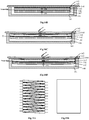
- the specific structure comprises a metal middle frame 81 having a recess, and the surface of the metal middle frame 81 is covered with a tempered glass 82 for protection.
- An assembly-inside-frame is accommodated within the recess, and the assembly-inside-frame comprises a polarizing sheet 83 of the display screen, a transparent touch sensing layer 84, a CF glass 85, a display driving layer 86 and a TFT glass 87 disposed successively from top to bottom.
- TFT glass 87 Under the TFT glass 87 are the other optical components of the display module, such as light guide plates, reflective films, etc.
- Certain air gap 88 or foam is present between the metal middle frame 81 and the assembly-inside-frame, which is bonded to the tempered glass 82 by glue or frame glue and is normally grounded.
- the transparent touch sensing layer 84 is multiplexed as a first electrode layer, the material of which is ITO, and the designed shape design of which isis a double vertical bar as shown in Fig. 9A .
- the display driving layer 86 is located between the CF glass 85 and the TFT glass 87, and the common electrode layer therein serves as a second electrode layer which is located on the lower surface of the CF glass and can be cut into a shape as shown in Fig. 9B , which forms a touch position sensing component together with the touch sensing layer 84 shown in Fig. 9A .
- the metal middle frame 81 serves as the third electrode layer.
- the air gap 88 or foam serves as the compressible layer.
- the touch control apparatus is initialized, and whether there is a finger touch is determined by comparing the detected mutual-capacitance value between the first and second electrode layers with the original value. If there is no finger touch, the self-capacitance value C21 of the first electrode layer in a fixed-level state and the self-capacitance value C25 of the first electrode layer in a suspended state are detected by setting electrodes of the second electrode layer to be at a fixed level or in a suspended state, as shown in Figs. 8 and 10A , and then C21 and C22 are calculated, wherein C25 is a series value of C21 and C22.
- the position of the touch point is detected by detecting the mutual-capacitance value between the first and second electrode layers, then the second electrode layer is set to be suspended and at a fixed level respectively, and the self-capacitance value C27 of the first electrode layer when the second electrode layer is in a fixed level state and the self-capacitance value C28 of the first electrode layer when the second electrode layer is in a suspended state, are detected.
- the self-capacitance value C27 is the parallel value of C21 and C22
- the self-capacitance value C28 is the sum value of C23 and the series capacitance value of C21 and C24.
- the pressure magnitude is obtained by comparing the value of C22 and C24.
- the advantages of the present embodiment are as follows: 1, it is possible to add a pressure detection to the original configuration of the touch screen of the touch control apparatus, and to enhance the user experience without increasing the cost; 2, the reliability is high and the consistency is good due to the use of the structure of the touch screen itself.
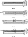
- the specific structure comprises an iron frame or a radiating sheet 121 and a support block 128 disposed on the iron frame or the radiating sheet 121, the structure further comprises a tempered glass 122 for protecting the display screen, a polarizing sheet 123, a touch sensing layer 124, a CF glass 125, a display driving layer 126, a TFT glass 127 , and the compressible layer 129 disposed successively from top to bottom, the TFT glass 127 is placed on the support block 128, and the compressible layer 129 is located in a space surrounded by the support block 128, the TFT glass 127, and the iron frame or the radiating sheet 121.
- Other optical components of the screen are disposed behind the TFT glass 127.
- the touch sensing layer 124 serves as a first electrode layer, the material of which is ITO, and the structure of which is a double vertical bar as shown in Fig. 9A .
- the common electrode layer in the display driving layer 126 is used as a second electrode layer and can be cut into a shape as shown in Fig. 9B .
- the support block 128 is a frame adhesive.
- the third electrode layer is a conductive iron frame or a radiating sheet 121, which is normally grounded. The detection method is the same as that of the first embodiment and will not be described in detail again.
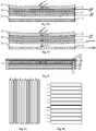
- Figs. 13A , 13B, 13C and 13D show a preferred embodiment in which the above touch detection device is applied to a Full In-cell touch control screen apparatus.
- the specific structure comprises a iron frame 131, and a glass 132 for protecting the screen, a polarizing sheet 133, a CF glass 134, a touch sensing layer 135, a TFT glass 136, a display driving layer 137 having a shielding function and the compressible layer 138 successively covering the iron frame 131 from top to bottom; the iron frame 131 has a recess, and the compressible layer 138 is placed in the recess.
- the touch sensing layer 135 is used as the first electrode layer, the material of which is ITO, etc., the specific structure of which is a rectangular lattice pattern as shown in Fig. 3C , the operation mode of which is self-capacitance detection, and the touch sensing layer 135 is located between the CF glass 134 of the display screen and the TFT glass 136.
- the common electrode layer having a shielding function in the display driving layer 137 serves as a third electrode layer, the specific structure of which has a rectangular shape as shown in Fig. 3C , and the state of which may be set to be suspended or at a fixed level.
- Figs. 14A , 14B, 14C and 14D show a preferred embodiment in which the above touch detection device is applied to an on-cell touch control screen apparatus.
- the specific structure comprises a metal middle frame 141, the surface of which is covered with a tempered glass 142 for protection.
- the metal middle frame 141 has a recess in which an assembly-inside-frame is accommodated, and the assembly-inside-frame comprises a polarizing sheet 143, a touch sensing layer 144, a CF glass 145, a display driving layer 146 and a TFT glass 147 disposed successively from top to bottom.
- Certain air gap 148 is present between the metal middle frame 141 and the assembly-inside-frame.
- the touch sensing layer 144 serves as the first electrode layer, the specific electrode pattern design of which is a single-layer triangular pattern as shown in Fig. 15A .
- a second electrode layer is a common electrode layer on the display driving layer 146, the material of which is ITO, etc., and the specific electrode pattern design of which is a flat plate structure as shown in Fig. 15B .
- the second electrode layer may be set to be at a fixed level or in a suspended state by a corresponding control circuit.
- the grounded metal middle frame 141 serves as the third electrode layer.
- the air gap 148 serves as a compressible layer.
- Figs. 16A, 16B, 16C and 16D show a preferred embodiment in which the above touch detection device is applied to an out-off-cell touch control screen apparatus.
- the specific structure comprises a metal middle frame 161 and a tempered glass 162 for protection covering the surface of the metal middle frame 161.
- the metal middle frame 161 has a recess in which an assembly-inside-frame is accommodated, and the assembly-inside-frame comprises a touch sensing layer 163, a polarizing sheet 164, a CF glass 165, a display driving layer 166 and a TFT glass 167 disposed successively from top to bottom.
- Certain air gap 168 presents between the metal middle frame 161 and the assembly-inside-frame, and is bonded to the tempered glass 162 by glue or frame glue and is normally grounded.
- the electrode design pattern of the touch sensing layer 163 is a double-layer vertical stripe pattern as shown in Fig. 17A , a thin film is provided between the upper electrode layer and the lower electrode layer, the operation mode thereof is mutual-capacitance, and the upper electrode layer may be multiplexed as the first electrode layer.
- the common electrode layer on the display driving layer 166 is a second electrode layer, the material of which is ITO, and the specific electrode pattern design of which is a flat plate structure as shown in Fig. 17B , and the common electrode layer may be set to be at a fixed level or in a suspended state by a corresponding control circuit.
- the lower electrode layer of the touch sensing layer 163 may also be multiplexed as the second electrode layer.
- the grounded metal middle frame 161 serves as a third electrode layer.
Claims (12)
- Dispositif de détection d'effleurement, comprenant :
un capteur d'effleurement (2) comprenant :une première couche d'électrode (21), une couche isolante rigide (24), une deuxième couche d'électrode (22), une couche compressible (25), et une troisième couche d'électrode (23) disposées successivement ;dans lequel la couche compressible (25) est configurée pour changer la distance entre la deuxième couche d'électrode (22) et la troisième couche d'électrode (23) lorsqu'elle est soumise à une pression d'effleurement ;la première couche d'électrode (21) est configurée pour former un composant de détection d'effleurement seule ou former un composant de détection d'effleurement conjointement avec la deuxième couche d'électrode (22) ; etla deuxième couche d'électrode (22) et la troisième couche d'électrode (23) forment une structure de condensateur, et une valeur de capacité de la structure de condensateur varie avec la distance entre la deuxième couche d'électrode (22) et la troisième couche d'électrode (23) ;un circuit de pilotage (1) configuré pour piloter la première couche d'électrode (21), la deuxième couche d'électrode (22) et la troisième couche d'électrode (23) avec un premier ensemble de signaux de pilotage lorsqu'aucune opération d'effleurement n'est réalisée, et piloter la première couche d'électrode (21), la deuxième couche d'électrode (22) et la troisième couche d'électrode (23) avec un second ensemble de signaux de pilotage lorsqu'une opération d'effleurement est réalisée ;une unité de détection de pression d'effleurement (3) configurée, lorsqu'aucune opération d'effleurement n'est réalisée, pour obtenir une première valeur de capacité de la structure de condensateur en détectant une valeur d'autocapacité de la première couche d'électrode (21), laquelle valeur d'autocapacité comporte une valeur de capacité entre la première couche d'électrode (21) et la deuxième couche d'électrode (22) et la première valeur de capacité, et, lorsqu'une opération d'effleurement est réalisée, pour obtenir une seconde valeur de capacité de la structure de condensateur en détectant une valeur d'autocapacité de la première couche d'électrode (21), laquelle valeur d'autocapacité comporte une valeur de capacité entre le doigt d'effleurement et la première couche d'électrode (21), une valeur de capacité entre la première couche d'électrode (21) et la deuxième couche d'électrode (22), et la seconde valeur de capacité, lorsqu'une opération d'effleurement est réalisée ; etl'unité de détection de pression d'effleurement (3) est en outre configurée pour ôter la valeur de capacité entre la première couche d'électrode (21) et la deuxième couche d'électrode (22) de la valeur d'autocapacité de la première couche d'électrode (21) détectée lorsqu'aucune opération d'effleurement n'est réalisée, et ôter la valeur de capacité entre la première couche d'électrode (21) et la deuxième couche d'électrode (22) et la valeur de capacité entre le doigt d'effleurement et la première couche d'électrode (21) de la valeur d'autocapacité de la première couche d'électrode (21) détectée lorsqu'une opération d'effleurement est réalisée, et calculer l'information de pression de l'opération d'effleurement de l'utilisateur à partir de la différence entre la première valeur de capacité et la seconde valeur de capacité. - Dispositif de détection d'effleurement selon la revendication 1, caractérisé en ce que :le circuit de pilotage (1) est configuré pour piloter la première couche d'électrode (21), la deuxième couche d'électrode (22) et la troisième couche d'électrode (23) lorsqu'aucune opération d'effleurement n'est réalisée de manière à piloter la première couche d'électrode (21) de façon constante avec un premier signal de pilotage, tout d'abord en entrant un premier signal de niveau fixe dans la deuxième couche d'électrode (22) puis en réglant la deuxième couche d'électrode (22) pour qu'elle soit dans un état suspendu, et en mettant à la terre la troisième couche d'électrode (23) ;l'unité de détection de pression d'effleurement (3) est configurée pour obtenir la première valeur de capacité en détectant la structure de condensateur lorsqu'aucune opération d'effleurement n'est réalisée de manière à détecter une valeur d'autocapacité C11 de la première couche d'électrode (21) tandis que la deuxième couche d'électrode (22) reçoit en entrée le premier signal de niveau fixe, à détecter une valeur d'autocapacité C15 de la première couche d'électrode (21) tandis que la deuxième couche d'électrode (22) est réglée pour être dans l'état suspendu et la troisième couche d'électrode (23) est mise à la terre, puis à calculer la première valeur de capacité C12 à partir de la valeur d'autocapacité C11 et de la valeur d'autocapacité C15 ;le circuit de pilotage (1) est configuré pour piloter la première couche d'électrode (21), la deuxième couche d'électrode (22) et la troisième couche d'électrode (23) lorsqu'une opération d'effleurement est réalisée de manière à piloter la première couche d'électrode (21) de façon constante avec un deuxième signal de pilotage, tout d'abord en entrant un second signal de niveau fixe dans la deuxième couche d'électrode (22) puis en réglant la deuxième couche d'électrode (22) pour qu'elle soit dans un état suspendu, et en mettant à la terre la troisième couche d'électrode (23) ;l'unité de détection de pression d'effleurement (3) est configurée pour obtenir la seconde valeur de capacité en détectant la structure de condensateur lorsqu'une opération d'effleurement est réalisée de manière à détecter une valeur d'autocapacité C16 de la première couche d'électrode (21) tandis que la deuxième couche d'électrode (22) reçoit en entrée le second signal de niveau fixe, à détecter une valeur d'autocapacité C18 de la première couche d'électrode (21) tandis que la deuxième couche d'électrode (22) est réglée pour être dans l'état suspendu et la troisième couche d'électrode (23) est mise à la terre, puis à calculer une valeur de capacité C13 entre un doigt d'effleurement et la première couche d'électrode (21) à partir de la valeur d'autocapacité C11 et de la valeur d'autocapacité C16 ; à calculer, à partir de la valeur de capacité C13 et de la valeur d'autocapacité C18, une valeur de série C19 de la valeur d'autocapacité C11 et de la seconde valeur de capacité ; puis à calculer la seconde valeur de capacité C14 à partir de la valeur de capacité C19 et de la valeur d'autocapacité C11 ; etl'unité de détection de pression d'effleurement (3) calcule enfin l'information de pression de l'opération d'effleurement de l'utilisateur à partir de la différence entre la première valeur de capacité C12 et la seconde valeur de capacité C14.
- Dispositif de détection d'effleurement selon la revendication 1, caractérisé en ce que,
le circuit de pilotage (1) est configuré pour piloter la première couche d'électrode (21), la deuxième couche d'électrode (22) et la troisième couche d'électrode (23) lorsqu'aucune opération d'effleurement n'est réalisée de manière à piloter la première couche d'électrode (21) avec un troisième signal de pilotage, à régler la deuxième couche d'électrode (22) pour qu'elle soit dans un état suspendu et à mettre à la terre la troisième couche d'électrode (23) ;
l'unité de détection de pression d'effleurement (3) est configurée pour obtenir la première valeur de capacité en détectant la structure de condensateur lorsqu'aucune opération d'effleurement n'est réalisée de manière à détecter une valeur d'autocapacité C75 de la première couche d'électrode (21) ; dans lequel la valeur d'autocapacité C75 est la valeur de série d'une valeur de capacité C71 et de la première valeur de capacité lorsqu'aucune opération d'effleurement n'est réalisée, la valeur de capacité C71 est la valeur de capacité entre la première couche d'électrode (21) et la deuxième couche d'électrode (22) ;
le circuit de pilotage (1) est configuré pour piloter la première couche d'électrode (21), la deuxième couche d'électrode (22) et la troisième couche d'électrode (23) lorsqu'une opération d'effleurement est réalisée de manière à piloter la première couche d'électrode (21) de façon constante avec un quatrième signal de pilotage, à piloter tout d'abord la deuxième couche d'électrode (22) avec le quatrième signal de pilotage puis à régler la deuxième couche d'électrode (22) pour qu'elle soit dans un état suspendu, et à mettre à la terre la troisième couche d'électrode (23) ; et
l'unité de détection de pression d'effleurement (3) est configurée pour obtenir la seconde valeur de capacité en détectant la structure de condensateur lorsqu'une opération d'effleurement est réalisée de manière à détecter une valeur de capacité C73 entre la première couche d'électrode (21) et un corps humain tandis que la deuxième couche d'électrode est pilotée avec le quatrième signal de pilotage, et à détecter une valeur d'autocapacité C76 de la première couche d'électrode (21) tandis que la deuxième couche d'électrode (22) est réglée pour être dans un état suspendu et la troisième couche d'électrode (23) est mise à la terre, puis à calculer, à partir de la valeur d'autocapacité C76 et de la valeur d'autocapacité C73, la valeur de série de la valeur de capacité C71 et de la seconde valeur de capacité lorsqu'une opération d'effleurement est réalisée ; à calculer enfin l'information de pression de l'opération d'effleurement de l'utilisateur à partir de la différence entre la valeur d'autocapacité C75 et la valeur d'autocapacité C76. - Appareil de commande à effleurement, caractérisé en ce qu'il comprend un dispositif de détection d'effleurement tel que décrit selon l'une quelconque des revendications 1 à 3.
- Appareil de commande à effleurement selon la revendication 4, caractérisé en ce que l'appareil de commande à effleurement comprend un cadre milieu en métal (81) avec un évidement ; la surface du cadre milieu en métal (81) est recouverte d'un verre trempé (82) à des fins de protection ; un cadre intérieur d'ensemble est logé au sein de l'évidement, et le cadre intérieur d'ensemble comprend une feuille polarisante (83) d'un écran d'affichage, une couche de détection d'effleurement transparente (84), un verre CF (85), une couche de pilotage d'affichage (86) et un verre TFT (87) disposés successivement de haut en bas ; un entrefer (88) ou une mousse est présent entre le cadre milieu en métal (81) et le cadre intérieur d'ensemble ;
dans lequel, la première couche d'électrode est la couche de détection d'effleurement transparente (84) ; la deuxième couche d'électrode est la couche d'électrode commune sur la couche de pilotage d'affichage (86) qui est située sur la surface inférieure du verre CF (85) ; la troisième couche d'électrode est le cadre milieu en métal (81) ; et la couche compressible est l'entrefer (88) ou la mousse. - Appareil de commande à effleurement selon la revendication 4, caractérisé en ce que l'appareil de commande à effleurement comprend un cadre en fer conducteur ou une feuille rayonnante (121) et un bloc de support (128) disposé sur le cadre en fer ou la feuille rayonnante (121), l'appareil de commande à effleurement comprend en outre un verre trempé (122) pour protéger un écran d'affichage, une feuille polarisante (123), une couche de détection d'effleurement (124), un verre CF (125), une couche de pilotage d'affichage (126), un verre TFT (127), et la couche compressible (129) disposés successivement de haut en bas, le verre TFT (127) est placé sur le bloc de support (128), et la couche compressible (129) est située dans un espace entouré par le bloc de support (128), le verre TFT (127) et le cadre en fer ou la feuille rayonnante (121) ;
dans lequel, la première couche d'électrode est la couche de détection d'effleurement transparente (124) ; la deuxième couche d'électrode est la couche d'électrode commune sur la couche de pilotage d'affichage (126) ; et la troisième couche d'électrode est le cadre en fer ou la feuille rayonnante (121). - Appareil de commande à effleurement selon la revendication 4, caractérisé en ce que l'appareil de commande à effleurement comprend un cadre en fer (131) et un verre (132) pour protéger un écran d'affichage, une feuille polarisante (133), un verre CF (134), une couche de détection d'effleurement (135), un verre TFT (136), une couche de pilotage d'affichage (137) avec une fonction de blindage et la couche compressible (138) couvrant successivement le cadre en fer (131) de haut en bas ; le cadre en fer (131) a un évidement, et la couche compressible (138) est placée dans l'évidement ;
dans lequel la première couche d'électrode est la couche de détection d'effleurement (135) ; la troisième couche d'électrode est la couche d'électrode commune sur la couche de pilotage d'affichage (137) avec une fonction de blindage. - Appareil de commande à effleurement selon la revendication 4, caractérisé en ce que l'appareil de commande à effleurement comprend un cadre milieu en métal (141) ayant un évidement ; la surface du cadre milieu en métal (141) est recouverte d'un verre trempé (142) à des fins de protection ; un cadre intérieur d'ensemble est logé au sein de l'évidement, et le cadre intérieur d'ensemble comprend une feuille polarisante (143), une couche de détection d'effleurement (144), un verre CF (145), une couche de pilotage d'affichage (146) et un verre TFT (147) disposés successivement de haut en bas ; un certain entrefer (148) est présent entre le cadre milieu en métal (141) et le cadre intérieur d'ensemble ;
dans lequel, la première couche d'électrode est la couche de détection d'effleurement (144) ; la deuxième couche d'électrode est la couche d'électrode commune sur la couche de pilotage d'affichage (146) : la troisième couche d'électrode est le cadre milieu en métal (141) ; et la couche compressible est l'entrefer (148). - Appareil de commande à effleurement selon la revendication 4, caractérisé en ce que l'appareil de commande à effleurement comprend un cadre milieu en métal (161) ayant un évidement ; la surface du cadre milieu en métal (161) est recouverte d'un verre trempé (162) à des fins de protection ; un cadre intérieur d'ensemble est logé au sein de l'évidement, et le cadre intérieur d'ensemble comprend une couche de détection d'effleurement (163), une feuille polarisante (164), un verre CF (165), une couche de pilotage d'affichage (166) et un verre TFT (167) disposés successivement de haut en bas ; un certain entrefer (168) est présent entre le cadre milieu en métal (161) et le cadre intérieur d'ensemble ;
dans lequel, la couche de détection d'effleurement (163) est configurée pour être des couches d'électrode doubles, qui comprennent une couche d'électrode supérieure et une couche d'électrode inférieure, la première couche d'électrode est la couche d'électrode supérieure ; la deuxième couche d'électrode est la couche d'électrode inférieure ou la couche d'électrode commune sur la couche de pilotage d'affichage (166) ; la troisième couche d'électrode est le cadre milieu en métal (161) ; et la couche compressible est l'entrefer (168). - Procédé de détection pour un dispositif de détection d'effleurement, dans lequel le dispositif de détection d'effleurement est le dispositif de détection d'effleurement selon la revendication 1 ; le procédé de détection comprenant :une première étape de pilotage consistant à piloter la première couche d'électrode (21), la deuxième couche d'électrode (22), et la troisième couche d'électrode (23) avec un premier ensemble de signaux de pilotage lorsqu'aucune opération d'effleurement n'est réalisée ; etune première étape de détection de valeur de capacité consistant à détecter une valeur d'autocapacité de la première couche d'électrode (21) lorsqu'aucune opération d'effleurement n'est réalisée, pour obtenir la première valeur de capacité de la structure de condensateur, dans lequel la valeur d'autocapacité détectée de la première couche d'électrode (21) inclut une valeur de capacité entre la première couche d'électrode (21) et la deuxième couche d'électrode (22), et la première valeur de capacité ;une seconde étape de pilotage consistant à piloter la première couche d'électrode (21), la deuxième couche d'électrode (22) et la troisième couche d'électrode (23) avec un second ensemble de signaux de pilotage lorsqu'une opération d'effleurement est réalisée ;une seconde étape de détection de valeur de capacité consistant à détecter une valeur d'autocapacité de la première couche d'électrode (21) lorsqu'une opération d'effleurement est réalisée, pour obtenir la seconde valeur de capacité de la structure de condensateur, dans lequel la valeur d'autocapacité détectée de la première couche d'électrode (21) inclut une valeur de capacité entre le doigt d'effleurement et la première couche d'électrode (21), une valeur de capacité entre la première couche d'électrode (21) et la deuxième couche d'électrode (22), et la seconde valeur de capacité ; etune étape de calcul de pression d'effleurement consistant à ôter la valeur de capacité entre la première couche d'électrode (21) et la deuxième couche d'électrode (22) de la valeur d'autocapacité de la première électrode détectée lorsqu'aucune opération d'effleurement n'est réalisée, et la valeur de capacité entre le doigt d'effleurement et la première couche d'électrode (21) de la valeur d'autocapacité de la première couche d'électrode (21) détectée lorsqu'une opération d'effleurement est réalisée, et à calculer l'information de pression de l'opération d'effleurement de l'utilisateur à partir de la différence entre la première valeur de capacité et la seconde valeur de capacité.
- Procédé de détection selon la revendication 10, caractérisé en ce que :la première étape de pilotage comprend : lorsqu'aucune opération d'effleurement n'est réalisée, le pilotage de la première couche d'électrode (21) de façon constante avec un premier signal de pilotage, l'entrée tout d'abord du premier signal de niveau fixe dans la deuxième couche d'électrode (22) puis le réglage de la deuxième couche d'électrode (22) pour qu'elle soit dans un état suspendu, et la mise à la terre de la troisième couche d'électrode (23) ;la première étape de détection de valeur de capacité comprend : lorsqu'aucune opération d'effleurement n'est réalisée, la détection d'une valeur d'autocapacité C11 de la première couche d'électrode (21) tandis que la deuxième couche d'électrode (22) reçoit en entrée le premier signal de niveau fixe, et la détection d'une valeur d'autocapacité C15 de la première couche d'électrode (21) tandis que la deuxième couche d'électrode est réglée pour être dans l'état suspendu et la troisième couche d'électrode (23) est mise à la terre ; puis le calcul d'une première valeur de capacité C12 à partir de la valeur d'autocapacité C11 et de la valeur d'autocapacité C15 ;la seconde étape de pilotage comprend : lorsqu'une opération d'effleurement est réalisée, le pilotage de la première couche d'électrode (21) pilotée de façon constante avec un deuxième signal de pilotage, l'entrée tout d'abord d'un second signal de niveau fixe dans la deuxième couche d'électrode (22) puis le réglage de la deuxième couche d'électrode (22) pour qu'elle soit dans un état suspendu, et la mise à la terre de la troisième couche d'électrode (23) ;la seconde étape de détection de valeur de capacité comprend : lorsqu'une opération d'effleurement est réalisée, la détection d'une valeur d'autocapacité C16 de la première couche d'électrode (21) tandis que la deuxième couche d'électrode (22) reçoit en entrée le second signal de niveau fixe, et la détection d'une valeur d'autocapacité C18 de la première couche d'électrode (21) tandis que la deuxième couche d'électrode (22) est réglée pour être dans l'état suspendu et la troisième couche d'électrode (23) est mise à la terre ; puis le calcul d'une valeur de capacité C13 entre le doigt d'effleurement et la première couche d'électrode (21) à partir de la valeur d'autocapacité C11 et de la valeur d'autocapacité C16 ; etle calcul, à partir de la valeur de capacité C13 et de la valeur d'autocapacité C18, d'une valeur de série C19 de la valeur d'autocapacité C11 et de la seconde valeur de capacité ; puis le calcul de la seconde valeur de capacité C14 à partir de la valeur de capacité C19 et de la valeur d'autocapacité C11 ; etl'étape de détection de pression d'effleurement comprend le calcul de l'information de pression de l'opération d'effleurement de l'utilisateur à partir de la différence entre la première valeur de capacité C12 et la seconde valeur de capacité C14.
- Procédé de détection selon la revendication 10, caractérisé en ce que :la première étape de pilotage comprend : lorsqu'aucune opération d'effleurement n'est réalisée, le pilotage de la première couche d'électrode (21) avec un troisième signal de pilotage, le réglage de la deuxième couche d'électrode (22) pour qu'elle soit dans un état suspendu et la mise à la terre de la troisième couche d'électrode (23) ;la première étape de détection de valeur de capacité comprend : lorsqu'aucune opération d'effleurement n'est réalisée, la détection d'une valeur d'autocapacité C75 de la première couche d'électrode (21) ; la valeur d'autocapacité C75 est la valeur de série d'une valeur de capacité C71 et de la première valeur de capacité lorsqu'aucune opération d'effleurement n'est réalisée, la valeur de capacité C71 est la valeur de capacité entre la première couche d'électrode (21) et la deuxième couche d'électrode (22) ;la seconde étape de pilotage comportant : lorsqu'une opération d'effleurement est réalisée, le pilotage de la première couche d'électrode (21) de façon constante avec un quatrième signal de pilotage, le pilotage tout d'abord de la deuxième couche d'électrode (22) avec le quatrième signal de pilotage puis le réglage de la deuxième couche d'électrode (22) pour qu'elle soit dans un état suspendu et la mise à la terre de la troisième couche d'électrode (23) ;la seconde étape de détection de valeur de capacité comprend : lorsqu'une opération d'effleurement est réalisée, la détection d'une valeur de capacité C73 entre la première couche d'électrode (21) et un corps humain tandis que la deuxième couche d'électrode (22) est pilotée avec le quatrième signal de pilotage, et la détection d'une valeur d'autocapacité C76 de la première couche d'électrode (21) tandis que la deuxième couche d'électrode (22) est réglée pour être dans un état suspendu et la troisième couche d'électrode (23) est mise à la terre ; puis le calcul, à partir de la valeur d'autocapacité C76 et de la valeur de capacité C73, de la valeur de série de la valeur de capacité C71 et de la seconde valeur de capacité lorsqu'une opération d'effleurement est réalisée ; etl'étape de calcul de pression d'effleurement comprend : le calcul de l'information de pression de l'opération d'effleurement de l'utilisateur à partir de la différence entre la valeur d'autocapacité C75 et la valeur d'autocapacité C76.
Applications Claiming Priority (1)
| Application Number | Priority Date | Filing Date | Title |
|---|---|---|---|
| PCT/CN2016/085999 WO2017214928A1 (fr) | 2016-06-16 | 2016-06-16 | Capteur tactile, appareil à détection tactile et procédé de détection, et dispositif à commande tactile |
Publications (3)
| Publication Number | Publication Date |
|---|---|
| EP3293617A1 EP3293617A1 (fr) | 2018-03-14 |
| EP3293617A4 EP3293617A4 (fr) | 2018-06-13 |
| EP3293617B1 true EP3293617B1 (fr) | 2020-01-29 |
Family
ID=57224365
Family Applications (1)
| Application Number | Title | Priority Date | Filing Date |
|---|---|---|---|
| EP16891891.0A Active EP3293617B1 (fr) | 2016-06-16 | 2016-06-16 | Capteur tactile, appareil à détection tactile et procédé de détection, et dispositif à commande tactile |
Country Status (5)
| Country | Link |
|---|---|
| US (1) | US10705660B2 (fr) |
| EP (1) | EP3293617B1 (fr) |
| KR (1) | KR102044083B1 (fr) |
| CN (1) | CN106104441B (fr) |
| WO (1) | WO2017214928A1 (fr) |
Families Citing this family (376)
| Publication number | Priority date | Publication date | Assignee | Title |
|---|---|---|---|---|
| US20070084897A1 (en) | 2003-05-20 | 2007-04-19 | Shelton Frederick E Iv | Articulating surgical stapling instrument incorporating a two-piece e-beam firing mechanism |
| US9060770B2 (en) | 2003-05-20 | 2015-06-23 | Ethicon Endo-Surgery, Inc. | Robotically-driven surgical instrument with E-beam driver |
| US8215531B2 (en) | 2004-07-28 | 2012-07-10 | Ethicon Endo-Surgery, Inc. | Surgical stapling instrument having a medical substance dispenser |
| US11896225B2 (en) | 2004-07-28 | 2024-02-13 | Cilag Gmbh International | Staple cartridge comprising a pan |
| US9237891B2 (en) | 2005-08-31 | 2016-01-19 | Ethicon Endo-Surgery, Inc. | Robotically-controlled surgical stapling devices that produce formed staples having different lengths |
| US7669746B2 (en) | 2005-08-31 | 2010-03-02 | Ethicon Endo-Surgery, Inc. | Staple cartridges for forming staples having differing formed staple heights |
| US10159482B2 (en) | 2005-08-31 | 2018-12-25 | Ethicon Llc | Fastener cartridge assembly comprising a fixed anvil and different staple heights |
| US11484312B2 (en) | 2005-08-31 | 2022-11-01 | Cilag Gmbh International | Staple cartridge comprising a staple driver arrangement |
| US7934630B2 (en) | 2005-08-31 | 2011-05-03 | Ethicon Endo-Surgery, Inc. | Staple cartridges for forming staples having differing formed staple heights |
| US11246590B2 (en) | 2005-08-31 | 2022-02-15 | Cilag Gmbh International | Staple cartridge including staple drivers having different unfired heights |
| US20070106317A1 (en) | 2005-11-09 | 2007-05-10 | Shelton Frederick E Iv | Hydraulically and electrically actuated articulation joints for surgical instruments |
| US11224427B2 (en) | 2006-01-31 | 2022-01-18 | Cilag Gmbh International | Surgical stapling system including a console and retraction assembly |
| US8820603B2 (en) | 2006-01-31 | 2014-09-02 | Ethicon Endo-Surgery, Inc. | Accessing data stored in a memory of a surgical instrument |
| US8186555B2 (en) | 2006-01-31 | 2012-05-29 | Ethicon Endo-Surgery, Inc. | Motor-driven surgical cutting and fastening instrument with mechanical closure system |
| US20110024477A1 (en) | 2009-02-06 | 2011-02-03 | Hall Steven G | Driven Surgical Stapler Improvements |
| US20110295295A1 (en) | 2006-01-31 | 2011-12-01 | Ethicon Endo-Surgery, Inc. | Robotically-controlled surgical instrument having recording capabilities |
| US7845537B2 (en) | 2006-01-31 | 2010-12-07 | Ethicon Endo-Surgery, Inc. | Surgical instrument having recording capabilities |
| US11278279B2 (en) | 2006-01-31 | 2022-03-22 | Cilag Gmbh International | Surgical instrument assembly |
| US8708213B2 (en) | 2006-01-31 | 2014-04-29 | Ethicon Endo-Surgery, Inc. | Surgical instrument having a feedback system |
| US7753904B2 (en) | 2006-01-31 | 2010-07-13 | Ethicon Endo-Surgery, Inc. | Endoscopic surgical instrument with a handle that can articulate with respect to the shaft |
| US20120292367A1 (en) | 2006-01-31 | 2012-11-22 | Ethicon Endo-Surgery, Inc. | Robotically-controlled end effector |
| US11793518B2 (en) | 2006-01-31 | 2023-10-24 | Cilag Gmbh International | Powered surgical instruments with firing system lockout arrangements |
| US8992422B2 (en) | 2006-03-23 | 2015-03-31 | Ethicon Endo-Surgery, Inc. | Robotically-controlled endoscopic accessory channel |
| US8322455B2 (en) | 2006-06-27 | 2012-12-04 | Ethicon Endo-Surgery, Inc. | Manually driven surgical cutting and fastening instrument |
| US10568652B2 (en) | 2006-09-29 | 2020-02-25 | Ethicon Llc | Surgical staples having attached drivers of different heights and stapling instruments for deploying the same |
| US11291441B2 (en) | 2007-01-10 | 2022-04-05 | Cilag Gmbh International | Surgical instrument with wireless communication between control unit and remote sensor |
| US8652120B2 (en) | 2007-01-10 | 2014-02-18 | Ethicon Endo-Surgery, Inc. | Surgical instrument with wireless communication between control unit and sensor transponders |
| US8684253B2 (en) | 2007-01-10 | 2014-04-01 | Ethicon Endo-Surgery, Inc. | Surgical instrument with wireless communication between a control unit of a robotic system and remote sensor |
| US11039836B2 (en) | 2007-01-11 | 2021-06-22 | Cilag Gmbh International | Staple cartridge for use with a surgical stapling instrument |
| US8701958B2 (en) | 2007-01-11 | 2014-04-22 | Ethicon Endo-Surgery, Inc. | Curved end effector for a surgical stapling device |
| US7669747B2 (en) | 2007-03-15 | 2010-03-02 | Ethicon Endo-Surgery, Inc. | Washer for use with a surgical stapling instrument |
| US8931682B2 (en) | 2007-06-04 | 2015-01-13 | Ethicon Endo-Surgery, Inc. | Robotically-controlled shaft based rotary drive systems for surgical instruments |
| US11564682B2 (en) | 2007-06-04 | 2023-01-31 | Cilag Gmbh International | Surgical stapler device |
| US7753245B2 (en) | 2007-06-22 | 2010-07-13 | Ethicon Endo-Surgery, Inc. | Surgical stapling instruments |
| US11849941B2 (en) | 2007-06-29 | 2023-12-26 | Cilag Gmbh International | Staple cartridge having staple cavities extending at a transverse angle relative to a longitudinal cartridge axis |
| US9179912B2 (en) | 2008-02-14 | 2015-11-10 | Ethicon Endo-Surgery, Inc. | Robotically-controlled motorized surgical cutting and fastening instrument |
| US8573465B2 (en) | 2008-02-14 | 2013-11-05 | Ethicon Endo-Surgery, Inc. | Robotically-controlled surgical end effector system with rotary actuated closure systems |
| US8758391B2 (en) | 2008-02-14 | 2014-06-24 | Ethicon Endo-Surgery, Inc. | Interchangeable tools for surgical instruments |
| US7819298B2 (en) | 2008-02-14 | 2010-10-26 | Ethicon Endo-Surgery, Inc. | Surgical stapling apparatus with control features operable with one hand |
| JP5410110B2 (ja) | 2008-02-14 | 2014-02-05 | エシコン・エンド−サージェリィ・インコーポレイテッド | Rf電極を有する外科用切断・固定器具 |
| US8636736B2 (en) | 2008-02-14 | 2014-01-28 | Ethicon Endo-Surgery, Inc. | Motorized surgical cutting and fastening instrument |
| US7866527B2 (en) | 2008-02-14 | 2011-01-11 | Ethicon Endo-Surgery, Inc. | Surgical stapling apparatus with interlockable firing system |
| US20130153641A1 (en) | 2008-02-15 | 2013-06-20 | Ethicon Endo-Surgery, Inc. | Releasable layer of material and surgical end effector having the same |
| US9005230B2 (en) | 2008-09-23 | 2015-04-14 | Ethicon Endo-Surgery, Inc. | Motorized surgical instrument |
| US11648005B2 (en) | 2008-09-23 | 2023-05-16 | Cilag Gmbh International | Robotically-controlled motorized surgical instrument with an end effector |
| US8210411B2 (en) | 2008-09-23 | 2012-07-03 | Ethicon Endo-Surgery, Inc. | Motor-driven surgical cutting instrument |
| US9386983B2 (en) | 2008-09-23 | 2016-07-12 | Ethicon Endo-Surgery, Llc | Robotically-controlled motorized surgical instrument |
| US8608045B2 (en) | 2008-10-10 | 2013-12-17 | Ethicon Endo-Sugery, Inc. | Powered surgical cutting and stapling apparatus with manually retractable firing system |
| US8517239B2 (en) | 2009-02-05 | 2013-08-27 | Ethicon Endo-Surgery, Inc. | Surgical stapling instrument comprising a magnetic element driver |
| EP2393430A1 (fr) | 2009-02-06 | 2011-12-14 | Ethicon Endo-Surgery, Inc. | Améliorations d'agrafeuse chirurgicale commandée |
| US8220688B2 (en) | 2009-12-24 | 2012-07-17 | Ethicon Endo-Surgery, Inc. | Motor-driven surgical cutting instrument with electric actuator directional control assembly |
| US8851354B2 (en) | 2009-12-24 | 2014-10-07 | Ethicon Endo-Surgery, Inc. | Surgical cutting instrument that analyzes tissue thickness |
| US8783543B2 (en) | 2010-07-30 | 2014-07-22 | Ethicon Endo-Surgery, Inc. | Tissue acquisition arrangements and methods for surgical stapling devices |
| US9566061B2 (en) | 2010-09-30 | 2017-02-14 | Ethicon Endo-Surgery, Llc | Fastener cartridge comprising a releasably attached tissue thickness compensator |
| US11849952B2 (en) | 2010-09-30 | 2023-12-26 | Cilag Gmbh International | Staple cartridge comprising staples positioned within a compressible portion thereof |
| US9839420B2 (en) | 2010-09-30 | 2017-12-12 | Ethicon Llc | Tissue thickness compensator comprising at least one medicament |
| US9629814B2 (en) | 2010-09-30 | 2017-04-25 | Ethicon Endo-Surgery, Llc | Tissue thickness compensator configured to redistribute compressive forces |
| US11298125B2 (en) | 2010-09-30 | 2022-04-12 | Cilag Gmbh International | Tissue stapler having a thickness compensator |
| US10945731B2 (en) | 2010-09-30 | 2021-03-16 | Ethicon Llc | Tissue thickness compensator comprising controlled release and expansion |
| US9386988B2 (en) | 2010-09-30 | 2016-07-12 | Ethicon End-Surgery, LLC | Retainer assembly including a tissue thickness compensator |
| US11812965B2 (en) | 2010-09-30 | 2023-11-14 | Cilag Gmbh International | Layer of material for a surgical end effector |
| US8746535B2 (en) | 2010-09-30 | 2014-06-10 | Ethicon Endo-Surgery, Inc. | Tissue thickness compensator comprising detachable portions |
| US8695866B2 (en) | 2010-10-01 | 2014-04-15 | Ethicon Endo-Surgery, Inc. | Surgical instrument having a power control circuit |
| AU2012250197B2 (en) | 2011-04-29 | 2017-08-10 | Ethicon Endo-Surgery, Inc. | Staple cartridge comprising staples positioned within a compressible portion thereof |
| US11207064B2 (en) | 2011-05-27 | 2021-12-28 | Cilag Gmbh International | Automated end effector component reloading system for use with a robotic system |
| US9072535B2 (en) | 2011-05-27 | 2015-07-07 | Ethicon Endo-Surgery, Inc. | Surgical stapling instruments with rotatable staple deployment arrangements |
| MX358135B (es) | 2012-03-28 | 2018-08-06 | Ethicon Endo Surgery Inc | Compensador de grosor de tejido que comprende una pluralidad de capas. |
| RU2639857C2 (ru) | 2012-03-28 | 2017-12-22 | Этикон Эндо-Серджери, Инк. | Компенсатор толщины ткани, содержащий капсулу для среды с низким давлением |
| RU2644272C2 (ru) | 2012-03-28 | 2018-02-08 | Этикон Эндо-Серджери, Инк. | Узел ограничения, включающий компенсатор толщины ткани |
| US9101358B2 (en) | 2012-06-15 | 2015-08-11 | Ethicon Endo-Surgery, Inc. | Articulatable surgical instrument comprising a firing drive |
| US11202631B2 (en) | 2012-06-28 | 2021-12-21 | Cilag Gmbh International | Stapling assembly comprising a firing lockout |
| US20140001231A1 (en) | 2012-06-28 | 2014-01-02 | Ethicon Endo-Surgery, Inc. | Firing system lockout arrangements for surgical instruments |
| US9289256B2 (en) | 2012-06-28 | 2016-03-22 | Ethicon Endo-Surgery, Llc | Surgical end effectors having angled tissue-contacting surfaces |
| US9226751B2 (en) | 2012-06-28 | 2016-01-05 | Ethicon Endo-Surgery, Inc. | Surgical instrument system including replaceable end effectors |
| BR112014032776B1 (pt) | 2012-06-28 | 2021-09-08 | Ethicon Endo-Surgery, Inc | Sistema de instrumento cirúrgico e kit cirúrgico para uso com um sistema de instrumento cirúrgico |
| EP2866686A1 (fr) | 2012-06-28 | 2015-05-06 | Ethicon Endo-Surgery, Inc. | Verrouillage de cartouche d'agrafes vide |
| US9649111B2 (en) | 2012-06-28 | 2017-05-16 | Ethicon Endo-Surgery, Llc | Replaceable clip cartridge for a clip applier |
| RU2669463C2 (ru) | 2013-03-01 | 2018-10-11 | Этикон Эндо-Серджери, Инк. | Хирургический инструмент с мягким упором |
| RU2672520C2 (ru) | 2013-03-01 | 2018-11-15 | Этикон Эндо-Серджери, Инк. | Шарнирно поворачиваемые хирургические инструменты с проводящими путями для передачи сигналов |
| US9629629B2 (en) | 2013-03-14 | 2017-04-25 | Ethicon Endo-Surgey, LLC | Control systems for surgical instruments |
| US9332987B2 (en) | 2013-03-14 | 2016-05-10 | Ethicon Endo-Surgery, Llc | Control arrangements for a drive member of a surgical instrument |
| US9867612B2 (en) | 2013-04-16 | 2018-01-16 | Ethicon Llc | Powered surgical stapler |
| BR112015026109B1 (pt) | 2013-04-16 | 2022-02-22 | Ethicon Endo-Surgery, Inc | Instrumento cirúrgico |
| MX369362B (es) | 2013-08-23 | 2019-11-06 | Ethicon Endo Surgery Llc | Dispositivos de retraccion de miembros de disparo para instrumentos quirurgicos electricos. |
| US9775609B2 (en) | 2013-08-23 | 2017-10-03 | Ethicon Llc | Tamper proof circuit for surgical instrument battery pack |
| US9962161B2 (en) | 2014-02-12 | 2018-05-08 | Ethicon Llc | Deliverable surgical instrument |
| US9826977B2 (en) | 2014-03-26 | 2017-11-28 | Ethicon Llc | Sterilization verification circuit |
| BR112016021943B1 (pt) | 2014-03-26 | 2022-06-14 | Ethicon Endo-Surgery, Llc | Instrumento cirúrgico para uso por um operador em um procedimento cirúrgico |
| US20150272557A1 (en) | 2014-03-26 | 2015-10-01 | Ethicon Endo-Surgery, Inc. | Modular surgical instrument system |
| JP6532889B2 (ja) | 2014-04-16 | 2019-06-19 | エシコン エルエルシーEthicon LLC | 締結具カートリッジ組立体及びステープル保持具カバー配置構成 |
| JP6612256B2 (ja) | 2014-04-16 | 2019-11-27 | エシコン エルエルシー | 不均一な締結具を備える締結具カートリッジ |
| US20150297223A1 (en) | 2014-04-16 | 2015-10-22 | Ethicon Endo-Surgery, Inc. | Fastener cartridges including extensions having different configurations |
| US9844369B2 (en) | 2014-04-16 | 2017-12-19 | Ethicon Llc | Surgical end effectors with firing element monitoring arrangements |
| CN106456176B (zh) | 2014-04-16 | 2019-06-28 | 伊西康内外科有限责任公司 | 包括具有不同构型的延伸部的紧固件仓 |
| US20160066913A1 (en) | 2014-09-05 | 2016-03-10 | Ethicon Endo-Surgery, Inc. | Local display of tissue parameter stabilization |
| BR112017004361B1 (pt) | 2014-09-05 | 2023-04-11 | Ethicon Llc | Sistema eletrônico para um instrumento cirúrgico |
| US11311294B2 (en) | 2014-09-05 | 2022-04-26 | Cilag Gmbh International | Powered medical device including measurement of closure state of jaws |
| US10105142B2 (en) | 2014-09-18 | 2018-10-23 | Ethicon Llc | Surgical stapler with plurality of cutting elements |
| JP6648119B2 (ja) | 2014-09-26 | 2020-02-14 | エシコン エルエルシーEthicon LLC | 外科ステープル留めバットレス及び付属物材料 |
| US11523821B2 (en) | 2014-09-26 | 2022-12-13 | Cilag Gmbh International | Method for creating a flexible staple line |
| US10076325B2 (en) | 2014-10-13 | 2018-09-18 | Ethicon Llc | Surgical stapling apparatus comprising a tissue stop |
| US9924944B2 (en) | 2014-10-16 | 2018-03-27 | Ethicon Llc | Staple cartridge comprising an adjunct material |
| US11141153B2 (en) | 2014-10-29 | 2021-10-12 | Cilag Gmbh International | Staple cartridges comprising driver arrangements |
| US10517594B2 (en) | 2014-10-29 | 2019-12-31 | Ethicon Llc | Cartridge assemblies for surgical staplers |
| US9844376B2 (en) | 2014-11-06 | 2017-12-19 | Ethicon Llc | Staple cartridge comprising a releasable adjunct material |
| US10736636B2 (en) | 2014-12-10 | 2020-08-11 | Ethicon Llc | Articulatable surgical instrument system |
| RU2703684C2 (ru) | 2014-12-18 | 2019-10-21 | ЭТИКОН ЭНДО-СЕРДЖЕРИ, ЭлЭлСи | Хирургический инструмент с упором, который выполнен с возможностью избирательного перемещения относительно кассеты со скобами вокруг дискретной неподвижной оси |
| US9844375B2 (en) | 2014-12-18 | 2017-12-19 | Ethicon Llc | Drive arrangements for articulatable surgical instruments |
| US9844374B2 (en) | 2014-12-18 | 2017-12-19 | Ethicon Llc | Surgical instrument systems comprising an articulatable end effector and means for adjusting the firing stroke of a firing member |
| US10004501B2 (en) | 2014-12-18 | 2018-06-26 | Ethicon Llc | Surgical instruments with improved closure arrangements |
| US10085748B2 (en) | 2014-12-18 | 2018-10-02 | Ethicon Llc | Locking arrangements for detachable shaft assemblies with articulatable surgical end effectors |
| US9987000B2 (en) | 2014-12-18 | 2018-06-05 | Ethicon Llc | Surgical instrument assembly comprising a flexible articulation system |
| US11154301B2 (en) | 2015-02-27 | 2021-10-26 | Cilag Gmbh International | Modular stapling assembly |
| JP2020121162A (ja) | 2015-03-06 | 2020-08-13 | エシコン エルエルシーEthicon LLC | 測定の安定性要素、クリープ要素、及び粘弾性要素を決定するためのセンサデータの時間依存性評価 |
| US9993248B2 (en) | 2015-03-06 | 2018-06-12 | Ethicon Endo-Surgery, Llc | Smart sensors with local signal processing |
| US10245033B2 (en) | 2015-03-06 | 2019-04-02 | Ethicon Llc | Surgical instrument comprising a lockable battery housing |
| US10052044B2 (en) | 2015-03-06 | 2018-08-21 | Ethicon Llc | Time dependent evaluation of sensor data to determine stability, creep, and viscoelastic elements of measures |
| US10687806B2 (en) | 2015-03-06 | 2020-06-23 | Ethicon Llc | Adaptive tissue compression techniques to adjust closure rates for multiple tissue types |
| US10441279B2 (en) | 2015-03-06 | 2019-10-15 | Ethicon Llc | Multiple level thresholds to modify operation of powered surgical instruments |
| US10617412B2 (en) | 2015-03-06 | 2020-04-14 | Ethicon Llc | System for detecting the mis-insertion of a staple cartridge into a surgical stapler |
| US9901342B2 (en) | 2015-03-06 | 2018-02-27 | Ethicon Endo-Surgery, Llc | Signal and power communication system positioned on a rotatable shaft |
| US10433844B2 (en) | 2015-03-31 | 2019-10-08 | Ethicon Llc | Surgical instrument with selectively disengageable threaded drive systems |
| US10835249B2 (en) | 2015-08-17 | 2020-11-17 | Ethicon Llc | Implantable layers for a surgical instrument |
| US10238386B2 (en) | 2015-09-23 | 2019-03-26 | Ethicon Llc | Surgical stapler having motor control based on an electrical parameter related to a motor current |
| US10105139B2 (en) | 2015-09-23 | 2018-10-23 | Ethicon Llc | Surgical stapler having downstream current-based motor control |
| US10299878B2 (en) | 2015-09-25 | 2019-05-28 | Ethicon Llc | Implantable adjunct systems for determining adjunct skew |
| US10980539B2 (en) | 2015-09-30 | 2021-04-20 | Ethicon Llc | Implantable adjunct comprising bonded layers |
| US10603039B2 (en) | 2015-09-30 | 2020-03-31 | Ethicon Llc | Progressively releasable implantable adjunct for use with a surgical stapling instrument |
| US10271849B2 (en) | 2015-09-30 | 2019-04-30 | Ethicon Llc | Woven constructs with interlocked standing fibers |
| US11890015B2 (en) | 2015-09-30 | 2024-02-06 | Cilag Gmbh International | Compressible adjunct with crossing spacer fibers |
| US10292704B2 (en) | 2015-12-30 | 2019-05-21 | Ethicon Llc | Mechanisms for compensating for battery pack failure in powered surgical instruments |
| US10265068B2 (en) | 2015-12-30 | 2019-04-23 | Ethicon Llc | Surgical instruments with separable motors and motor control circuits |
| US10368865B2 (en) | 2015-12-30 | 2019-08-06 | Ethicon Llc | Mechanisms for compensating for drivetrain failure in powered surgical instruments |
| BR112018016098B1 (pt) | 2016-02-09 | 2023-02-23 | Ethicon Llc | Instrumento cirúrgico |
| US11213293B2 (en) | 2016-02-09 | 2022-01-04 | Cilag Gmbh International | Articulatable surgical instruments with single articulation link arrangements |
| US10448948B2 (en) | 2016-02-12 | 2019-10-22 | Ethicon Llc | Mechanisms for compensating for drivetrain failure in powered surgical instruments |
| US11224426B2 (en) | 2016-02-12 | 2022-01-18 | Cilag Gmbh International | Mechanisms for compensating for drivetrain failure in powered surgical instruments |
| US11179150B2 (en) | 2016-04-15 | 2021-11-23 | Cilag Gmbh International | Systems and methods for controlling a surgical stapling and cutting instrument |
| US10456137B2 (en) | 2016-04-15 | 2019-10-29 | Ethicon Llc | Staple formation detection mechanisms |
| US10426467B2 (en) | 2016-04-15 | 2019-10-01 | Ethicon Llc | Surgical instrument with detection sensors |
| US11607239B2 (en) | 2016-04-15 | 2023-03-21 | Cilag Gmbh International | Systems and methods for controlling a surgical stapling and cutting instrument |
| US10335145B2 (en) | 2016-04-15 | 2019-07-02 | Ethicon Llc | Modular surgical instrument with configurable operating mode |
| US10492783B2 (en) | 2016-04-15 | 2019-12-03 | Ethicon, Llc | Surgical instrument with improved stop/start control during a firing motion |
| US10357247B2 (en) | 2016-04-15 | 2019-07-23 | Ethicon Llc | Surgical instrument with multiple program responses during a firing motion |
| US10828028B2 (en) | 2016-04-15 | 2020-11-10 | Ethicon Llc | Surgical instrument with multiple program responses during a firing motion |
| US10426469B2 (en) | 2016-04-18 | 2019-10-01 | Ethicon Llc | Surgical instrument comprising a primary firing lockout and a secondary firing lockout |
| US20170296173A1 (en) | 2016-04-18 | 2017-10-19 | Ethicon Endo-Surgery, Llc | Method for operating a surgical instrument |
| US11317917B2 (en) | 2016-04-18 | 2022-05-03 | Cilag Gmbh International | Surgical stapling system comprising a lockable firing assembly |
| TWI633369B (zh) * | 2016-08-12 | 2018-08-21 | 鴻海精密工業股份有限公司 | 顯示裝置 |
| CN106527813B (zh) * | 2016-11-22 | 2019-05-10 | 厦门天马微电子有限公司 | 一种触控显示面板及触控显示面板的驱动方法 |
| CN106527809B (zh) * | 2016-11-22 | 2019-08-02 | 厦门天马微电子有限公司 | 一种触控显示面板及其驱动方法 |
| DE102016124485A1 (de) * | 2016-12-15 | 2018-06-21 | Valeo Schalter Und Sensoren Gmbh | Bedienvorrichtung mit einer ersten und einer zweiten kapazitiven Messeinheit, Kraftfahrzeug, sowie Verfahren zum Betreiben einer Bedienvorrichtung |
| US10888322B2 (en) | 2016-12-21 | 2021-01-12 | Ethicon Llc | Surgical instrument comprising a cutting member |
| US10568625B2 (en) | 2016-12-21 | 2020-02-25 | Ethicon Llc | Staple cartridges and arrangements of staples and staple cavities therein |
| US20180168598A1 (en) | 2016-12-21 | 2018-06-21 | Ethicon Endo-Surgery, Llc | Staple forming pocket arrangements comprising zoned forming surface grooves |
| MX2019007311A (es) | 2016-12-21 | 2019-11-18 | Ethicon Llc | Sistemas de engrapado quirurgico. |
| JP6983893B2 (ja) | 2016-12-21 | 2021-12-17 | エシコン エルエルシーEthicon LLC | 外科用エンドエフェクタ及び交換式ツールアセンブリのためのロックアウト構成 |
| US11191540B2 (en) | 2016-12-21 | 2021-12-07 | Cilag Gmbh International | Protective cover arrangements for a joint interface between a movable jaw and actuator shaft of a surgical instrument |
| US10568624B2 (en) | 2016-12-21 | 2020-02-25 | Ethicon Llc | Surgical instruments with jaws that are pivotable about a fixed axis and include separate and distinct closure and firing systems |
| US11090048B2 (en) | 2016-12-21 | 2021-08-17 | Cilag Gmbh International | Method for resetting a fuse of a surgical instrument shaft |
| US20180168625A1 (en) | 2016-12-21 | 2018-06-21 | Ethicon Endo-Surgery, Llc | Surgical stapling instruments with smart staple cartridges |
| US10588630B2 (en) | 2016-12-21 | 2020-03-17 | Ethicon Llc | Surgical tool assemblies with closure stroke reduction features |
| US10856868B2 (en) | 2016-12-21 | 2020-12-08 | Ethicon Llc | Firing member pin configurations |
| US20180168615A1 (en) | 2016-12-21 | 2018-06-21 | Ethicon Endo-Surgery, Llc | Method of deforming staples from two different types of staple cartridges with the same surgical stapling instrument |
| US11419606B2 (en) | 2016-12-21 | 2022-08-23 | Cilag Gmbh International | Shaft assembly comprising a clutch configured to adapt the output of a rotary firing member to two different systems |
| US11134942B2 (en) | 2016-12-21 | 2021-10-05 | Cilag Gmbh International | Surgical stapling instruments and staple-forming anvils |
| US10675025B2 (en) | 2016-12-21 | 2020-06-09 | Ethicon Llc | Shaft assembly comprising separately actuatable and retractable systems |
| JP7010956B2 (ja) | 2016-12-21 | 2022-01-26 | エシコン エルエルシー | 組織をステープル留めする方法 |
| US10695055B2 (en) | 2016-12-21 | 2020-06-30 | Ethicon Llc | Firing assembly comprising a lockout |
| US10610224B2 (en) | 2016-12-21 | 2020-04-07 | Ethicon Llc | Lockout arrangements for surgical end effectors and replaceable tool assemblies |
| CN108700973B (zh) * | 2016-12-22 | 2021-07-23 | 深圳市汇顶科技股份有限公司 | 电容检测电路及电子装置 |
| WO2018112860A1 (fr) * | 2016-12-22 | 2018-06-28 | 深圳市汇顶科技股份有限公司 | Circuit de détection de capacité, et appareil électronique |
| CN106775100B (zh) * | 2016-12-28 | 2020-01-17 | 厦门天马微电子有限公司 | 触控显示面板和包含其的触控显示装置 |
| CN107153482B (zh) * | 2017-03-20 | 2021-08-17 | 联想(北京)有限公司 | 金属触控板及电子设备 |
| CN107153483B (zh) * | 2017-05-09 | 2019-12-03 | 京东方科技集团股份有限公司 | 一种触控显示模组、显示装置及其驱动方法 |
| US10646220B2 (en) | 2017-06-20 | 2020-05-12 | Ethicon Llc | Systems and methods for controlling displacement member velocity for a surgical instrument |
| US10307170B2 (en) | 2017-06-20 | 2019-06-04 | Ethicon Llc | Method for closed loop control of motor velocity of a surgical stapling and cutting instrument |
| US11090046B2 (en) | 2017-06-20 | 2021-08-17 | Cilag Gmbh International | Systems and methods for controlling displacement member motion of a surgical stapling and cutting instrument |
| US10779820B2 (en) | 2017-06-20 | 2020-09-22 | Ethicon Llc | Systems and methods for controlling motor speed according to user input for a surgical instrument |
| US10980537B2 (en) | 2017-06-20 | 2021-04-20 | Ethicon Llc | Closed loop feedback control of motor velocity of a surgical stapling and cutting instrument based on measured time over a specified number of shaft rotations |
| US11517325B2 (en) | 2017-06-20 | 2022-12-06 | Cilag Gmbh International | Closed loop feedback control of motor velocity of a surgical stapling and cutting instrument based on measured displacement distance traveled over a specified time interval |
| US10888321B2 (en) | 2017-06-20 | 2021-01-12 | Ethicon Llc | Systems and methods for controlling velocity of a displacement member of a surgical stapling and cutting instrument |
| USD890784S1 (en) | 2017-06-20 | 2020-07-21 | Ethicon Llc | Display panel with changeable graphical user interface |
| US10881399B2 (en) | 2017-06-20 | 2021-01-05 | Ethicon Llc | Techniques for adaptive control of motor velocity of a surgical stapling and cutting instrument |
| US11071554B2 (en) | 2017-06-20 | 2021-07-27 | Cilag Gmbh International | Closed loop feedback control of motor velocity of a surgical stapling and cutting instrument based on magnitude of velocity error measurements |
| US11382638B2 (en) | 2017-06-20 | 2022-07-12 | Cilag Gmbh International | Closed loop feedback control of motor velocity of a surgical stapling and cutting instrument based on measured time over a specified displacement distance |
| US11653914B2 (en) | 2017-06-20 | 2023-05-23 | Cilag Gmbh International | Systems and methods for controlling motor velocity of a surgical stapling and cutting instrument according to articulation angle of end effector |
| US10631859B2 (en) | 2017-06-27 | 2020-04-28 | Ethicon Llc | Articulation systems for surgical instruments |
| US11266405B2 (en) | 2017-06-27 | 2022-03-08 | Cilag Gmbh International | Surgical anvil manufacturing methods |
| US11324503B2 (en) | 2017-06-27 | 2022-05-10 | Cilag Gmbh International | Surgical firing member arrangements |
| US10856869B2 (en) | 2017-06-27 | 2020-12-08 | Ethicon Llc | Surgical anvil arrangements |
| US10993716B2 (en) | 2017-06-27 | 2021-05-04 | Ethicon Llc | Surgical anvil arrangements |
| US10903685B2 (en) | 2017-06-28 | 2021-01-26 | Ethicon Llc | Surgical shaft assemblies with slip ring assemblies forming capacitive channels |
| US10716614B2 (en) | 2017-06-28 | 2020-07-21 | Ethicon Llc | Surgical shaft assemblies with slip ring assemblies with increased contact pressure |
| US20190000461A1 (en) | 2017-06-28 | 2019-01-03 | Ethicon Llc | Surgical cutting and fastening devices with pivotable anvil with a tissue locating arrangement in close proximity to an anvil pivot axis |
| US11564686B2 (en) | 2017-06-28 | 2023-01-31 | Cilag Gmbh International | Surgical shaft assemblies with flexible interfaces |
| US11259805B2 (en) | 2017-06-28 | 2022-03-01 | Cilag Gmbh International | Surgical instrument comprising firing member supports |
| US11246592B2 (en) | 2017-06-28 | 2022-02-15 | Cilag Gmbh International | Surgical instrument comprising an articulation system lockable to a frame |
| USD906355S1 (en) | 2017-06-28 | 2020-12-29 | Ethicon Llc | Display screen or portion thereof with a graphical user interface for a surgical instrument |
| EP4070740A1 (fr) | 2017-06-28 | 2022-10-12 | Cilag GmbH International | Instrument chirurgical comprenant des coupleurs rotatifs actionnables de façon sélective |
| US10765427B2 (en) | 2017-06-28 | 2020-09-08 | Ethicon Llc | Method for articulating a surgical instrument |
| US11678880B2 (en) | 2017-06-28 | 2023-06-20 | Cilag Gmbh International | Surgical instrument comprising a shaft including a housing arrangement |
| US11007022B2 (en) | 2017-06-29 | 2021-05-18 | Ethicon Llc | Closed loop velocity control techniques based on sensed tissue parameters for robotic surgical instrument |
| US10932772B2 (en) | 2017-06-29 | 2021-03-02 | Ethicon Llc | Methods for closed loop velocity control for robotic surgical instrument |
| US10898183B2 (en) | 2017-06-29 | 2021-01-26 | Ethicon Llc | Robotic surgical instrument with closed loop feedback techniques for advancement of closure member during firing |
| US11944300B2 (en) | 2017-08-03 | 2024-04-02 | Cilag Gmbh International | Method for operating a surgical system bailout |
| US11471155B2 (en) | 2017-08-03 | 2022-10-18 | Cilag Gmbh International | Surgical system bailout |
| US11304695B2 (en) | 2017-08-03 | 2022-04-19 | Cilag Gmbh International | Surgical system shaft interconnection |
| CN107688411B (zh) * | 2017-09-14 | 2019-11-22 | 京东方科技集团股份有限公司 | 基板及其感测方法、触控面板和显示装置 |
| USD907647S1 (en) | 2017-09-29 | 2021-01-12 | Ethicon Llc | Display screen or portion thereof with animated graphical user interface |
| USD907648S1 (en) | 2017-09-29 | 2021-01-12 | Ethicon Llc | Display screen or portion thereof with animated graphical user interface |
| US11399829B2 (en) | 2017-09-29 | 2022-08-02 | Cilag Gmbh International | Systems and methods of initiating a power shutdown mode for a surgical instrument |
| US10765429B2 (en) | 2017-09-29 | 2020-09-08 | Ethicon Llc | Systems and methods for providing alerts according to the operational state of a surgical instrument |
| USD917500S1 (en) | 2017-09-29 | 2021-04-27 | Ethicon Llc | Display screen or portion thereof with graphical user interface |
| US10743872B2 (en) | 2017-09-29 | 2020-08-18 | Ethicon Llc | System and methods for controlling a display of a surgical instrument |
| US11134944B2 (en) | 2017-10-30 | 2021-10-05 | Cilag Gmbh International | Surgical stapler knife motion controls |
| US11090075B2 (en) | 2017-10-30 | 2021-08-17 | Cilag Gmbh International | Articulation features for surgical end effector |
| US10842490B2 (en) | 2017-10-31 | 2020-11-24 | Ethicon Llc | Cartridge body design with force reduction based on firing completion |
| US10779903B2 (en) | 2017-10-31 | 2020-09-22 | Ethicon Llc | Positive shaft rotation lock activated by jaw closure |
| AU2017441729B2 (en) * | 2017-11-30 | 2021-05-27 | Honor Device Co., Ltd. | Structural assembly and mobile terminal |
| US10779825B2 (en) | 2017-12-15 | 2020-09-22 | Ethicon Llc | Adapters with end effector position sensing and control arrangements for use in connection with electromechanical surgical instruments |
| US10828033B2 (en) | 2017-12-15 | 2020-11-10 | Ethicon Llc | Handheld electromechanical surgical instruments with improved motor control arrangements for positioning components of an adapter coupled thereto |
| US11033267B2 (en) | 2017-12-15 | 2021-06-15 | Ethicon Llc | Systems and methods of controlling a clamping member firing rate of a surgical instrument |
| US10869666B2 (en) | 2017-12-15 | 2020-12-22 | Ethicon Llc | Adapters with control systems for controlling multiple motors of an electromechanical surgical instrument |
| US10779826B2 (en) | 2017-12-15 | 2020-09-22 | Ethicon Llc | Methods of operating surgical end effectors |
| US10966718B2 (en) | 2017-12-15 | 2021-04-06 | Ethicon Llc | Dynamic clamping assemblies with improved wear characteristics for use in connection with electromechanical surgical instruments |
| US10743874B2 (en) | 2017-12-15 | 2020-08-18 | Ethicon Llc | Sealed adapters for use with electromechanical surgical instruments |
| US11006955B2 (en) | 2017-12-15 | 2021-05-18 | Ethicon Llc | End effectors with positive jaw opening features for use with adapters for electromechanical surgical instruments |
| US10687813B2 (en) | 2017-12-15 | 2020-06-23 | Ethicon Llc | Adapters with firing stroke sensing arrangements for use in connection with electromechanical surgical instruments |
| US10743875B2 (en) | 2017-12-15 | 2020-08-18 | Ethicon Llc | Surgical end effectors with jaw stiffener arrangements configured to permit monitoring of firing member |
| US11071543B2 (en) | 2017-12-15 | 2021-07-27 | Cilag Gmbh International | Surgical end effectors with clamping assemblies configured to increase jaw aperture ranges |
| US11197670B2 (en) | 2017-12-15 | 2021-12-14 | Cilag Gmbh International | Surgical end effectors with pivotal jaws configured to touch at their respective distal ends when fully closed |
| US11045270B2 (en) | 2017-12-19 | 2021-06-29 | Cilag Gmbh International | Robotic attachment comprising exterior drive actuator |
| US11020112B2 (en) | 2017-12-19 | 2021-06-01 | Ethicon Llc | Surgical tools configured for interchangeable use with different controller interfaces |
| US10716565B2 (en) | 2017-12-19 | 2020-07-21 | Ethicon Llc | Surgical instruments with dual articulation drivers |
| US10729509B2 (en) | 2017-12-19 | 2020-08-04 | Ethicon Llc | Surgical instrument comprising closure and firing locking mechanism |
| USD910847S1 (en) | 2017-12-19 | 2021-02-16 | Ethicon Llc | Surgical instrument assembly |
| US10835330B2 (en) | 2017-12-19 | 2020-11-17 | Ethicon Llc | Method for determining the position of a rotatable jaw of a surgical instrument attachment assembly |
| US11311290B2 (en) | 2017-12-21 | 2022-04-26 | Cilag Gmbh International | Surgical instrument comprising an end effector dampener |
| US11076853B2 (en) | 2017-12-21 | 2021-08-03 | Cilag Gmbh International | Systems and methods of displaying a knife position during transection for a surgical instrument |
| US11129680B2 (en) | 2017-12-21 | 2021-09-28 | Cilag Gmbh International | Surgical instrument comprising a projector |
| US11337691B2 (en) | 2017-12-21 | 2022-05-24 | Cilag Gmbh International | Surgical instrument configured to determine firing path |
| EP3567461B1 (fr) * | 2018-03-12 | 2021-01-13 | Shenzhen Goodix Technology Co., Ltd. | Puce de détection de pression et procédé de détection de pression |
| CN108731855B (zh) * | 2018-05-18 | 2019-07-26 | 京东方科技集团股份有限公司 | 一种压力传感单元及压力传感器、压力传感装置 |
| US11291440B2 (en) | 2018-08-20 | 2022-04-05 | Cilag Gmbh International | Method for operating a powered articulatable surgical instrument |
| US11324501B2 (en) | 2018-08-20 | 2022-05-10 | Cilag Gmbh International | Surgical stapling devices with improved closure members |
| US10912559B2 (en) | 2018-08-20 | 2021-02-09 | Ethicon Llc | Reinforced deformable anvil tip for surgical stapler anvil |
| US10779821B2 (en) | 2018-08-20 | 2020-09-22 | Ethicon Llc | Surgical stapler anvils with tissue stop features configured to avoid tissue pinch |
| US11253256B2 (en) | 2018-08-20 | 2022-02-22 | Cilag Gmbh International | Articulatable motor powered surgical instruments with dedicated articulation motor arrangements |
| US11207065B2 (en) | 2018-08-20 | 2021-12-28 | Cilag Gmbh International | Method for fabricating surgical stapler anvils |
| US11083458B2 (en) | 2018-08-20 | 2021-08-10 | Cilag Gmbh International | Powered surgical instruments with clutching arrangements to convert linear drive motions to rotary drive motions |
| US10842492B2 (en) | 2018-08-20 | 2020-11-24 | Ethicon Llc | Powered articulatable surgical instruments with clutching and locking arrangements for linking an articulation drive system to a firing drive system |
| US10856870B2 (en) | 2018-08-20 | 2020-12-08 | Ethicon Llc | Switching arrangements for motor powered articulatable surgical instruments |
| US11045192B2 (en) | 2018-08-20 | 2021-06-29 | Cilag Gmbh International | Fabricating techniques for surgical stapler anvils |
| US11039834B2 (en) | 2018-08-20 | 2021-06-22 | Cilag Gmbh International | Surgical stapler anvils with staple directing protrusions and tissue stability features |
| USD914878S1 (en) | 2018-08-20 | 2021-03-30 | Ethicon Llc | Surgical instrument anvil |
| CN109144319B (zh) * | 2018-08-22 | 2022-04-08 | 京东方科技集团股份有限公司 | 传感结构、显示设备及传感结构的驱动方法 |
| US20220147183A1 (en) * | 2018-12-13 | 2022-05-12 | Shenzhen Royole Technologies Co., Ltd. | Touch panel and touch detection method |
| EP3686941A1 (fr) * | 2019-01-25 | 2020-07-29 | Robert Bosch GmbH | Procédé de production d'un dispositif électronique á couches et dispositif électronique á couches |
| CN111516617A (zh) * | 2019-02-01 | 2020-08-11 | 佛吉亚(中国)投资有限公司 | 用于车辆内饰的触控模块及包括该触控模块的内饰和车辆 |
| US11172929B2 (en) | 2019-03-25 | 2021-11-16 | Cilag Gmbh International | Articulation drive arrangements for surgical systems |
| US11696761B2 (en) | 2019-03-25 | 2023-07-11 | Cilag Gmbh International | Firing drive arrangements for surgical systems |
| US11147551B2 (en) | 2019-03-25 | 2021-10-19 | Cilag Gmbh International | Firing drive arrangements for surgical systems |
| US11147553B2 (en) | 2019-03-25 | 2021-10-19 | Cilag Gmbh International | Firing drive arrangements for surgical systems |
| US11426251B2 (en) | 2019-04-30 | 2022-08-30 | Cilag Gmbh International | Articulation directional lights on a surgical instrument |
| US11471157B2 (en) | 2019-04-30 | 2022-10-18 | Cilag Gmbh International | Articulation control mapping for a surgical instrument |
| US11648009B2 (en) | 2019-04-30 | 2023-05-16 | Cilag Gmbh International | Rotatable jaw tip for a surgical instrument |
| US11432816B2 (en) | 2019-04-30 | 2022-09-06 | Cilag Gmbh International | Articulation pin for a surgical instrument |
| US11253254B2 (en) | 2019-04-30 | 2022-02-22 | Cilag Gmbh International | Shaft rotation actuator on a surgical instrument |
| US11903581B2 (en) | 2019-04-30 | 2024-02-20 | Cilag Gmbh International | Methods for stapling tissue using a surgical instrument |
| US11452528B2 (en) | 2019-04-30 | 2022-09-27 | Cilag Gmbh International | Articulation actuators for a surgical instrument |
| CN110134281B (zh) * | 2019-05-16 | 2022-09-16 | 上海艾为电子技术股份有限公司 | 电容检测系统及方法 |
| CN110134280A (zh) * | 2019-05-16 | 2019-08-16 | 上海艾为电子技术股份有限公司 | 电容传感器压力检测系统和方法 |
| CN110347298A (zh) * | 2019-06-21 | 2019-10-18 | 武汉华星光电半导体显示技术有限公司 | 一种触摸屏及其控制方法 |
| US11298127B2 (en) | 2019-06-28 | 2022-04-12 | Cilag GmbH Interational | Surgical stapling system having a lockout mechanism for an incompatible cartridge |
| US11660163B2 (en) | 2019-06-28 | 2023-05-30 | Cilag Gmbh International | Surgical system with RFID tags for updating motor assembly parameters |
| US11771419B2 (en) | 2019-06-28 | 2023-10-03 | Cilag Gmbh International | Packaging for a replaceable component of a surgical stapling system |
| US11399837B2 (en) | 2019-06-28 | 2022-08-02 | Cilag Gmbh International | Mechanisms for motor control adjustments of a motorized surgical instrument |
| US11291451B2 (en) | 2019-06-28 | 2022-04-05 | Cilag Gmbh International | Surgical instrument with battery compatibility verification functionality |
| US11241235B2 (en) | 2019-06-28 | 2022-02-08 | Cilag Gmbh International | Method of using multiple RFID chips with a surgical assembly |
| US11627959B2 (en) | 2019-06-28 | 2023-04-18 | Cilag Gmbh International | Surgical instruments including manual and powered system lockouts |
| US11464601B2 (en) | 2019-06-28 | 2022-10-11 | Cilag Gmbh International | Surgical instrument comprising an RFID system for tracking a movable component |
| US11259803B2 (en) | 2019-06-28 | 2022-03-01 | Cilag Gmbh International | Surgical stapling system having an information encryption protocol |
| US11684434B2 (en) | 2019-06-28 | 2023-06-27 | Cilag Gmbh International | Surgical RFID assemblies for instrument operational setting control |
| US11298132B2 (en) | 2019-06-28 | 2022-04-12 | Cilag GmbH Inlernational | Staple cartridge including a honeycomb extension |
| US11478241B2 (en) | 2019-06-28 | 2022-10-25 | Cilag Gmbh International | Staple cartridge including projections |
| US11638587B2 (en) | 2019-06-28 | 2023-05-02 | Cilag Gmbh International | RFID identification systems for surgical instruments |
| US11497492B2 (en) | 2019-06-28 | 2022-11-15 | Cilag Gmbh International | Surgical instrument including an articulation lock |
| US11051807B2 (en) | 2019-06-28 | 2021-07-06 | Cilag Gmbh International | Packaging assembly including a particulate trap |
| US11219455B2 (en) | 2019-06-28 | 2022-01-11 | Cilag Gmbh International | Surgical instrument including a lockout key |
| US11376098B2 (en) | 2019-06-28 | 2022-07-05 | Cilag Gmbh International | Surgical instrument system comprising an RFID system |
| US11246678B2 (en) | 2019-06-28 | 2022-02-15 | Cilag Gmbh International | Surgical stapling system having a frangible RFID tag |
| US11553971B2 (en) | 2019-06-28 | 2023-01-17 | Cilag Gmbh International | Surgical RFID assemblies for display and communication |
| US11426167B2 (en) | 2019-06-28 | 2022-08-30 | Cilag Gmbh International | Mechanisms for proper anvil attachment surgical stapling head assembly |
| US11523822B2 (en) | 2019-06-28 | 2022-12-13 | Cilag Gmbh International | Battery pack including a circuit interrupter |
| US11224497B2 (en) | 2019-06-28 | 2022-01-18 | Cilag Gmbh International | Surgical systems with multiple RFID tags |
| US11504122B2 (en) | 2019-12-19 | 2022-11-22 | Cilag Gmbh International | Surgical instrument comprising a nested firing member |
| US11607219B2 (en) | 2019-12-19 | 2023-03-21 | Cilag Gmbh International | Staple cartridge comprising a detachable tissue cutting knife |
| US11304696B2 (en) | 2019-12-19 | 2022-04-19 | Cilag Gmbh International | Surgical instrument comprising a powered articulation system |
| US11529137B2 (en) | 2019-12-19 | 2022-12-20 | Cilag Gmbh International | Staple cartridge comprising driver retention members |
| US11464512B2 (en) | 2019-12-19 | 2022-10-11 | Cilag Gmbh International | Staple cartridge comprising a curved deck surface |
| US11234698B2 (en) | 2019-12-19 | 2022-02-01 | Cilag Gmbh International | Stapling system comprising a clamp lockout and a firing lockout |
| US11701111B2 (en) | 2019-12-19 | 2023-07-18 | Cilag Gmbh International | Method for operating a surgical stapling instrument |
| US11911032B2 (en) | 2019-12-19 | 2024-02-27 | Cilag Gmbh International | Staple cartridge comprising a seating cam |
| US11931033B2 (en) | 2019-12-19 | 2024-03-19 | Cilag Gmbh International | Staple cartridge comprising a latch lockout |
| US11559304B2 (en) | 2019-12-19 | 2023-01-24 | Cilag Gmbh International | Surgical instrument comprising a rapid closure mechanism |
| US11529139B2 (en) | 2019-12-19 | 2022-12-20 | Cilag Gmbh International | Motor driven surgical instrument |
| US11446029B2 (en) | 2019-12-19 | 2022-09-20 | Cilag Gmbh International | Staple cartridge comprising projections extending from a curved deck surface |
| US11576672B2 (en) | 2019-12-19 | 2023-02-14 | Cilag Gmbh International | Surgical instrument comprising a closure system including a closure member and an opening member driven by a drive screw |
| US11291447B2 (en) | 2019-12-19 | 2022-04-05 | Cilag Gmbh International | Stapling instrument comprising independent jaw closing and staple firing systems |
| US11844520B2 (en) | 2019-12-19 | 2023-12-19 | Cilag Gmbh International | Staple cartridge comprising driver retention members |
| USD975850S1 (en) | 2020-06-02 | 2023-01-17 | Cilag Gmbh International | Staple cartridge |
| USD974560S1 (en) | 2020-06-02 | 2023-01-03 | Cilag Gmbh International | Staple cartridge |
| USD975851S1 (en) | 2020-06-02 | 2023-01-17 | Cilag Gmbh International | Staple cartridge |
| USD976401S1 (en) | 2020-06-02 | 2023-01-24 | Cilag Gmbh International | Staple cartridge |
| USD966512S1 (en) | 2020-06-02 | 2022-10-11 | Cilag Gmbh International | Staple cartridge |
| USD975278S1 (en) | 2020-06-02 | 2023-01-10 | Cilag Gmbh International | Staple cartridge |
| USD967421S1 (en) | 2020-06-02 | 2022-10-18 | Cilag Gmbh International | Staple cartridge |
| US11883024B2 (en) | 2020-07-28 | 2024-01-30 | Cilag Gmbh International | Method of operating a surgical instrument |
| US11526236B2 (en) | 2020-09-07 | 2022-12-13 | Samsung Electro-Mechanics Co., Ltd. | Touch sensing device |
| US11931025B2 (en) | 2020-10-29 | 2024-03-19 | Cilag Gmbh International | Surgical instrument comprising a releasable closure drive lock |
| US11517390B2 (en) | 2020-10-29 | 2022-12-06 | Cilag Gmbh International | Surgical instrument comprising a limited travel switch |
| US11779330B2 (en) | 2020-10-29 | 2023-10-10 | Cilag Gmbh International | Surgical instrument comprising a jaw alignment system |
| US11717289B2 (en) | 2020-10-29 | 2023-08-08 | Cilag Gmbh International | Surgical instrument comprising an indicator which indicates that an articulation drive is actuatable |
| US11617577B2 (en) | 2020-10-29 | 2023-04-04 | Cilag Gmbh International | Surgical instrument comprising a sensor configured to sense whether an articulation drive of the surgical instrument is actuatable |
| USD1013170S1 (en) | 2020-10-29 | 2024-01-30 | Cilag Gmbh International | Surgical instrument assembly |
| US11452526B2 (en) | 2020-10-29 | 2022-09-27 | Cilag Gmbh International | Surgical instrument comprising a staged voltage regulation start-up system |
| US11534259B2 (en) | 2020-10-29 | 2022-12-27 | Cilag Gmbh International | Surgical instrument comprising an articulation indicator |
| US11844518B2 (en) | 2020-10-29 | 2023-12-19 | Cilag Gmbh International | Method for operating a surgical instrument |
| US11896217B2 (en) | 2020-10-29 | 2024-02-13 | Cilag Gmbh International | Surgical instrument comprising an articulation lock |
| USD980425S1 (en) | 2020-10-29 | 2023-03-07 | Cilag Gmbh International | Surgical instrument assembly |
| US11678882B2 (en) | 2020-12-02 | 2023-06-20 | Cilag Gmbh International | Surgical instruments with interactive features to remedy incidental sled movements |
| US11653915B2 (en) | 2020-12-02 | 2023-05-23 | Cilag Gmbh International | Surgical instruments with sled location detection and adjustment features |
| US11744581B2 (en) | 2020-12-02 | 2023-09-05 | Cilag Gmbh International | Powered surgical instruments with multi-phase tissue treatment |
| US11627960B2 (en) | 2020-12-02 | 2023-04-18 | Cilag Gmbh International | Powered surgical instruments with smart reload with separately attachable exteriorly mounted wiring connections |
| US11944296B2 (en) | 2020-12-02 | 2024-04-02 | Cilag Gmbh International | Powered surgical instruments with external connectors |
| US11653920B2 (en) | 2020-12-02 | 2023-05-23 | Cilag Gmbh International | Powered surgical instruments with communication interfaces through sterile barrier |
| US11849943B2 (en) | 2020-12-02 | 2023-12-26 | Cilag Gmbh International | Surgical instrument with cartridge release mechanisms |
| US11890010B2 (en) | 2020-12-02 | 2024-02-06 | Cllag GmbH International | Dual-sided reinforced reload for surgical instruments |
| US11737751B2 (en) | 2020-12-02 | 2023-08-29 | Cilag Gmbh International | Devices and methods of managing energy dissipated within sterile barriers of surgical instrument housings |
| US11793514B2 (en) | 2021-02-26 | 2023-10-24 | Cilag Gmbh International | Staple cartridge comprising sensor array which may be embedded in cartridge body |
| US11749877B2 (en) | 2021-02-26 | 2023-09-05 | Cilag Gmbh International | Stapling instrument comprising a signal antenna |
| US11723657B2 (en) | 2021-02-26 | 2023-08-15 | Cilag Gmbh International | Adjustable communication based on available bandwidth and power capacity |
| US11950779B2 (en) | 2021-02-26 | 2024-04-09 | Cilag Gmbh International | Method of powering and communicating with a staple cartridge |
| US11812964B2 (en) | 2021-02-26 | 2023-11-14 | Cilag Gmbh International | Staple cartridge comprising a power management circuit |
| US11925349B2 (en) | 2021-02-26 | 2024-03-12 | Cilag Gmbh International | Adjustment to transfer parameters to improve available power |
| US11744583B2 (en) | 2021-02-26 | 2023-09-05 | Cilag Gmbh International | Distal communication array to tune frequency of RF systems |
| US11696757B2 (en) | 2021-02-26 | 2023-07-11 | Cilag Gmbh International | Monitoring of internal systems to detect and track cartridge motion status |
| US11950777B2 (en) | 2021-02-26 | 2024-04-09 | Cilag Gmbh International | Staple cartridge comprising an information access control system |
| US11701113B2 (en) | 2021-02-26 | 2023-07-18 | Cilag Gmbh International | Stapling instrument comprising a separate power antenna and a data transfer antenna |
| US11751869B2 (en) | 2021-02-26 | 2023-09-12 | Cilag Gmbh International | Monitoring of multiple sensors over time to detect moving characteristics of tissue |
| US11730473B2 (en) | 2021-02-26 | 2023-08-22 | Cilag Gmbh International | Monitoring of manufacturing life-cycle |
| US11759202B2 (en) | 2021-03-22 | 2023-09-19 | Cilag Gmbh International | Staple cartridge comprising an implantable layer |
| US11826012B2 (en) | 2021-03-22 | 2023-11-28 | Cilag Gmbh International | Stapling instrument comprising a pulsed motor-driven firing rack |
| US11737749B2 (en) | 2021-03-22 | 2023-08-29 | Cilag Gmbh International | Surgical stapling instrument comprising a retraction system |
| US11826042B2 (en) | 2021-03-22 | 2023-11-28 | Cilag Gmbh International | Surgical instrument comprising a firing drive including a selectable leverage mechanism |
| US11717291B2 (en) | 2021-03-22 | 2023-08-08 | Cilag Gmbh International | Staple cartridge comprising staples configured to apply different tissue compression |
| US11723658B2 (en) | 2021-03-22 | 2023-08-15 | Cilag Gmbh International | Staple cartridge comprising a firing lockout |
| US11806011B2 (en) | 2021-03-22 | 2023-11-07 | Cilag Gmbh International | Stapling instrument comprising tissue compression systems |
| US11849944B2 (en) | 2021-03-24 | 2023-12-26 | Cilag Gmbh International | Drivers for fastener cartridge assemblies having rotary drive screws |
| US11786239B2 (en) | 2021-03-24 | 2023-10-17 | Cilag Gmbh International | Surgical instrument articulation joint arrangements comprising multiple moving linkage features |
| US11832816B2 (en) | 2021-03-24 | 2023-12-05 | Cilag Gmbh International | Surgical stapling assembly comprising nonplanar staples and planar staples |
| US11849945B2 (en) | 2021-03-24 | 2023-12-26 | Cilag Gmbh International | Rotary-driven surgical stapling assembly comprising eccentrically driven firing member |
| US11896219B2 (en) | 2021-03-24 | 2024-02-13 | Cilag Gmbh International | Mating features between drivers and underside of a cartridge deck |
| US11857183B2 (en) | 2021-03-24 | 2024-01-02 | Cilag Gmbh International | Stapling assembly components having metal substrates and plastic bodies |
| US11744603B2 (en) | 2021-03-24 | 2023-09-05 | Cilag Gmbh International | Multi-axis pivot joints for surgical instruments and methods for manufacturing same |
| US11896218B2 (en) | 2021-03-24 | 2024-02-13 | Cilag Gmbh International | Method of using a powered stapling device |
| US11903582B2 (en) | 2021-03-24 | 2024-02-20 | Cilag Gmbh International | Leveraging surfaces for cartridge installation |
| US11944336B2 (en) | 2021-03-24 | 2024-04-02 | Cilag Gmbh International | Joint arrangements for multi-planar alignment and support of operational drive shafts in articulatable surgical instruments |
| US11793516B2 (en) | 2021-03-24 | 2023-10-24 | Cilag Gmbh International | Surgical staple cartridge comprising longitudinal support beam |
| US11786243B2 (en) | 2021-03-24 | 2023-10-17 | Cilag Gmbh International | Firing members having flexible portions for adapting to a load during a surgical firing stroke |
| US11826047B2 (en) | 2021-05-28 | 2023-11-28 | Cilag Gmbh International | Stapling instrument comprising jaw mounts |
| US11877745B2 (en) | 2021-10-18 | 2024-01-23 | Cilag Gmbh International | Surgical stapling assembly having longitudinally-repeating staple leg clusters |
| US11957337B2 (en) | 2021-10-18 | 2024-04-16 | Cilag Gmbh International | Surgical stapling assembly with offset ramped drive surfaces |
| US11937816B2 (en) | 2021-10-28 | 2024-03-26 | Cilag Gmbh International | Electrical lead arrangements for surgical instruments |
| KR102614955B1 (ko) * | 2022-06-08 | 2023-12-20 | 어보브반도체 주식회사 | 개선된 압력 터치를 감지하는 방법 및 장치 |
Citations (2)
| Publication number | Priority date | Publication date | Assignee | Title |
|---|---|---|---|---|
| US20150296062A1 (en) * | 2014-04-11 | 2015-10-15 | Lg Electronics Inc. | Mobile terminal and method for controlling the same |
| US20160162088A1 (en) * | 2014-08-01 | 2016-06-09 | Hideep Inc. | Smartphone |
Family Cites Families (19)
| Publication number | Priority date | Publication date | Assignee | Title |
|---|---|---|---|---|
| US5942733A (en) * | 1992-06-08 | 1999-08-24 | Synaptics, Inc. | Stylus input capacitive touchpad sensor |
| WO1997040482A1 (fr) * | 1996-04-24 | 1997-10-30 | Logitech, Inc. | Procede et dispositif pour detecter le contact et la pression |
| US5945980A (en) * | 1997-11-14 | 1999-08-31 | Logitech, Inc. | Touchpad with active plane for pen detection |
| US20140267152A1 (en) * | 2013-03-12 | 2014-09-18 | Mircrochip Technology Incorporated | Force Sensing X-Y Touch Sensor |
| US10817096B2 (en) * | 2014-02-06 | 2020-10-27 | Apple Inc. | Force sensor incorporated into display |
| CN103076935B (zh) * | 2013-01-18 | 2016-05-25 | 敦泰电子有限公司 | 触控显示屏及其显示电极的制作方法、显示电极和电子设备 |
| CN108415634B (zh) * | 2013-08-30 | 2020-12-15 | 烟台正海科技股份有限公司 | 一种触控装置 |
| US10120506B2 (en) * | 2013-11-12 | 2018-11-06 | Microsoft Technology Licensing, Llc | Multi-touch capacitive sensing surface |
| CN103927065B (zh) * | 2014-01-27 | 2017-02-15 | 上海中航光电子有限公司 | 一种检测触摸屏的方法及触摸屏 |
| US20160062500A1 (en) * | 2014-08-28 | 2016-03-03 | Apple Inc. | Force Sensor with Capacitive Gap Sensing |
| KR20160039767A (ko) * | 2014-10-01 | 2016-04-12 | 삼성디스플레이 주식회사 | 터치 센서를 포함하는 표시 장치 |
| CN106249937B (zh) * | 2015-06-05 | 2019-02-26 | 株式会社日本显示器 | 带触摸检测功能的显示装置以及显示系统 |
| KR102411047B1 (ko) * | 2015-09-30 | 2022-06-17 | 엘지디스플레이 주식회사 | 포스 터치 기능을 갖는 전자 기기 |
| CN205230007U (zh) * | 2015-12-09 | 2016-05-11 | 南昌欧菲光科技有限公司 | 触摸显示装置 |
| CN105549790B (zh) * | 2016-01-26 | 2019-08-20 | 宸盛光电有限公司 | 一种压力感测触控模组 |
| JP6581927B2 (ja) * | 2016-03-09 | 2019-09-25 | 株式会社ジャパンディスプレイ | 検出装置、表示装置及び電子機器 |
| JP6700896B2 (ja) * | 2016-03-25 | 2020-05-27 | 株式会社ジャパンディスプレイ | 検出装置及びタッチ検出機能付き表示装置 |
| CN105676509A (zh) * | 2016-03-25 | 2016-06-15 | 武汉华星光电技术有限公司 | 压力触控液晶显示面板及制作方法 |
| US20170322657A1 (en) * | 2016-05-05 | 2017-11-09 | Himax Technologies Limited | Touch display |
-
2016
- 2016-06-16 WO PCT/CN2016/085999 patent/WO2017214928A1/fr active Application Filing
- 2016-06-16 KR KR1020177025017A patent/KR102044083B1/ko active IP Right Grant
- 2016-06-16 CN CN201680000657.5A patent/CN106104441B/zh active Active
- 2016-06-16 EP EP16891891.0A patent/EP3293617B1/fr active Active
-
2017
- 2017-09-05 US US15/695,200 patent/US10705660B2/en active Active
Patent Citations (2)
| Publication number | Priority date | Publication date | Assignee | Title |
|---|---|---|---|---|
| US20150296062A1 (en) * | 2014-04-11 | 2015-10-15 | Lg Electronics Inc. | Mobile terminal and method for controlling the same |
| US20160162088A1 (en) * | 2014-08-01 | 2016-06-09 | Hideep Inc. | Smartphone |
Also Published As
| Publication number | Publication date |
|---|---|
| KR20180018479A (ko) | 2018-02-21 |
| CN106104441A (zh) | 2016-11-09 |
| US20170364183A1 (en) | 2017-12-21 |
| KR102044083B1 (ko) | 2019-11-12 |
| WO2017214928A1 (fr) | 2017-12-21 |
| CN106104441B (zh) | 2019-02-01 |
| US10705660B2 (en) | 2020-07-07 |
| EP3293617A4 (fr) | 2018-06-13 |
| EP3293617A1 (fr) | 2018-03-14 |
Similar Documents
| Publication | Publication Date | Title |
|---|---|---|
| EP3293617B1 (fr) | Capteur tactile, appareil à détection tactile et procédé de détection, et dispositif à commande tactile | |
| TWI605369B (zh) | 互容式壓力感測器以及具有壓力感測功能之觸控顯示裝置與其壓力感測方法 | |
| US10025411B2 (en) | Touch screen and pressure touch detection method thereof | |
| CN204926052U (zh) | 触摸显示装置 | |
| EP3040828B1 (fr) | Panneau tactile et dispositif d'affichage comprenant celui-ci | |
| EP2544081B1 (fr) | Capteur de détection de position, dispositif de détection de position et procédé de détection de position | |
| US8169332B2 (en) | Tactile device with force sensitive touch input surface | |
| WO2017045362A1 (fr) | Écran tactile et son procédé de détection de commande tactile par pression | |
| KR20160039765A (ko) | 터치 센서를 포함하는 표시 장치 | |
| GB2462170A (en) | Capacitive touch screen or touchpad for Finger or Stylus | |
| KR20160039767A (ko) | 터치 센서를 포함하는 표시 장치 | |
| CN108369468B (zh) | 三维触摸屏面板及其压力感测层 | |
| CN106249953B (zh) | 一种压感触摸屏及显示装置 | |
| CN107924243B (zh) | 压力感应触摸系统及具有压力感应触摸系统的计算装置 | |
| KR101816549B1 (ko) | 터치 디스플레이 장치 | |
| WO2008133432A1 (fr) | Structure d'application de signal pour écran tactile à fenêtre associée | |
| EP3229117B1 (fr) | Dispositif d'affichage tactile et unité de rétroéclairage de celui-ci | |
| US20190138125A1 (en) | Differential force sensing referenced to display | |
| KR20160018894A (ko) | 압력 감지가 가능한 터치 스크린 패널 | |
| KR102021218B1 (ko) | 단말 | |
| KR20180031863A (ko) | 구동 회로, 터치 디스플레이 장치 및 그 구동 방법 | |
| CN106502479B (zh) | 触摸显示装置 | |
| CN112925445B (zh) | 触控模组、显示模组、显示装置及检测方法 | |
| TWM519275U (zh) | 功能玻璃罩蓋 | |
| CN107045397B (zh) | 压力传感装置及其制造方法 |
Legal Events
| Date | Code | Title | Description |
|---|---|---|---|
| STAA | Information on the status of an ep patent application or granted ep patent |
Free format text: STATUS: UNKNOWN |
|
| STAA | Information on the status of an ep patent application or granted ep patent |
Free format text: STATUS: THE INTERNATIONAL PUBLICATION HAS BEEN MADE |
|
| PUAI | Public reference made under article 153(3) epc to a published international application that has entered the european phase |
Free format text: ORIGINAL CODE: 0009012 |
|
| STAA | Information on the status of an ep patent application or granted ep patent |
Free format text: STATUS: REQUEST FOR EXAMINATION WAS MADE |
|
| 17P | Request for examination filed |
Effective date: 20170905 |
|
| AK | Designated contracting states |
Kind code of ref document: A1 Designated state(s): AL AT BE BG CH CY CZ DE DK EE ES FI FR GB GR HR HU IE IS IT LI LT LU LV MC MK MT NL NO PL PT RO RS SE SI SK SM TR |
|
| AX | Request for extension of the european patent |
Extension state: BA ME |
|
| R17P | Request for examination filed (corrected) |
Effective date: 20170905 |
|
| A4 | Supplementary search report drawn up and despatched |
Effective date: 20180516 |
|
| RIC1 | Information provided on ipc code assigned before grant |
Ipc: G06F 3/041 20060101AFI20180508BHEP Ipc: G06F 3/044 20060101ALI20180508BHEP |
|
| STAA | Information on the status of an ep patent application or granted ep patent |
Free format text: STATUS: EXAMINATION IS IN PROGRESS |
|
| 17Q | First examination report despatched |
Effective date: 20190207 |
|
| GRAP | Despatch of communication of intention to grant a patent |
Free format text: ORIGINAL CODE: EPIDOSNIGR1 |
|
| STAA | Information on the status of an ep patent application or granted ep patent |
Free format text: STATUS: GRANT OF PATENT IS INTENDED |
|
| DAV | Request for validation of the european patent (deleted) | ||
| DAX | Request for extension of the european patent (deleted) | ||
| INTG | Intention to grant announced |
Effective date: 20190807 |
|
| GRAS | Grant fee paid |
Free format text: ORIGINAL CODE: EPIDOSNIGR3 |
|
| GRAA | (expected) grant |
Free format text: ORIGINAL CODE: 0009210 |
|
| STAA | Information on the status of an ep patent application or granted ep patent |
Free format text: STATUS: THE PATENT HAS BEEN GRANTED |
|
| AK | Designated contracting states |
Kind code of ref document: B1 Designated state(s): AL AT BE BG CH CY CZ DE DK EE ES FI FR GB GR HR HU IE IS IT LI LT LU LV MC MK MT NL NO PL PT RO RS SE SI SK SM TR |
|
| REG | Reference to a national code |
Ref country code: GB Ref legal event code: FG4D |
|
| REG | Reference to a national code |
Ref country code: CH Ref legal event code: EP |
|
| REG | Reference to a national code |
Ref country code: AT Ref legal event code: REF Ref document number: 1228936 Country of ref document: AT Kind code of ref document: T Effective date: 20200215 |
|
| REG | Reference to a national code |
Ref country code: IE Ref legal event code: FG4D |
|
| REG | Reference to a national code |
Ref country code: DE Ref legal event code: R096 Ref document number: 602016028988 Country of ref document: DE |
|
| REG | Reference to a national code |
Ref country code: NL Ref legal event code: MP Effective date: 20200129 |
|
| PG25 | Lapsed in a contracting state [announced via postgrant information from national office to epo] |
Ref country code: PT Free format text: LAPSE BECAUSE OF FAILURE TO SUBMIT A TRANSLATION OF THE DESCRIPTION OR TO PAY THE FEE WITHIN THE PRESCRIBED TIME-LIMIT Effective date: 20200621 Ref country code: RS Free format text: LAPSE BECAUSE OF FAILURE TO SUBMIT A TRANSLATION OF THE DESCRIPTION OR TO PAY THE FEE WITHIN THE PRESCRIBED TIME-LIMIT Effective date: 20200129 Ref country code: NO Free format text: LAPSE BECAUSE OF FAILURE TO SUBMIT A TRANSLATION OF THE DESCRIPTION OR TO PAY THE FEE WITHIN THE PRESCRIBED TIME-LIMIT Effective date: 20200429 Ref country code: FI Free format text: LAPSE BECAUSE OF FAILURE TO SUBMIT A TRANSLATION OF THE DESCRIPTION OR TO PAY THE FEE WITHIN THE PRESCRIBED TIME-LIMIT Effective date: 20200129 |
|
| REG | Reference to a national code |
Ref country code: LT Ref legal event code: MG4D |
|
| PG25 | Lapsed in a contracting state [announced via postgrant information from national office to epo] |
Ref country code: BG Free format text: LAPSE BECAUSE OF FAILURE TO SUBMIT A TRANSLATION OF THE DESCRIPTION OR TO PAY THE FEE WITHIN THE PRESCRIBED TIME-LIMIT Effective date: 20200429 Ref country code: HR Free format text: LAPSE BECAUSE OF FAILURE TO SUBMIT A TRANSLATION OF THE DESCRIPTION OR TO PAY THE FEE WITHIN THE PRESCRIBED TIME-LIMIT Effective date: 20200129 Ref country code: LV Free format text: LAPSE BECAUSE OF FAILURE TO SUBMIT A TRANSLATION OF THE DESCRIPTION OR TO PAY THE FEE WITHIN THE PRESCRIBED TIME-LIMIT Effective date: 20200129 Ref country code: SE Free format text: LAPSE BECAUSE OF FAILURE TO SUBMIT A TRANSLATION OF THE DESCRIPTION OR TO PAY THE FEE WITHIN THE PRESCRIBED TIME-LIMIT Effective date: 20200129 Ref country code: IS Free format text: LAPSE BECAUSE OF FAILURE TO SUBMIT A TRANSLATION OF THE DESCRIPTION OR TO PAY THE FEE WITHIN THE PRESCRIBED TIME-LIMIT Effective date: 20200529 Ref country code: GR Free format text: LAPSE BECAUSE OF FAILURE TO SUBMIT A TRANSLATION OF THE DESCRIPTION OR TO PAY THE FEE WITHIN THE PRESCRIBED TIME-LIMIT Effective date: 20200430 |
|
| PG25 | Lapsed in a contracting state [announced via postgrant information from national office to epo] |
Ref country code: NL Free format text: LAPSE BECAUSE OF FAILURE TO SUBMIT A TRANSLATION OF THE DESCRIPTION OR TO PAY THE FEE WITHIN THE PRESCRIBED TIME-LIMIT Effective date: 20200129 |
|
| PG25 | Lapsed in a contracting state [announced via postgrant information from national office to epo] |
Ref country code: ES Free format text: LAPSE BECAUSE OF FAILURE TO SUBMIT A TRANSLATION OF THE DESCRIPTION OR TO PAY THE FEE WITHIN THE PRESCRIBED TIME-LIMIT Effective date: 20200129 Ref country code: CZ Free format text: LAPSE BECAUSE OF FAILURE TO SUBMIT A TRANSLATION OF THE DESCRIPTION OR TO PAY THE FEE WITHIN THE PRESCRIBED TIME-LIMIT Effective date: 20200129 Ref country code: SK Free format text: LAPSE BECAUSE OF FAILURE TO SUBMIT A TRANSLATION OF THE DESCRIPTION OR TO PAY THE FEE WITHIN THE PRESCRIBED TIME-LIMIT Effective date: 20200129 Ref country code: LT Free format text: LAPSE BECAUSE OF FAILURE TO SUBMIT A TRANSLATION OF THE DESCRIPTION OR TO PAY THE FEE WITHIN THE PRESCRIBED TIME-LIMIT Effective date: 20200129 Ref country code: RO Free format text: LAPSE BECAUSE OF FAILURE TO SUBMIT A TRANSLATION OF THE DESCRIPTION OR TO PAY THE FEE WITHIN THE PRESCRIBED TIME-LIMIT Effective date: 20200129 Ref country code: DK Free format text: LAPSE BECAUSE OF FAILURE TO SUBMIT A TRANSLATION OF THE DESCRIPTION OR TO PAY THE FEE WITHIN THE PRESCRIBED TIME-LIMIT Effective date: 20200129 Ref country code: SM Free format text: LAPSE BECAUSE OF FAILURE TO SUBMIT A TRANSLATION OF THE DESCRIPTION OR TO PAY THE FEE WITHIN THE PRESCRIBED TIME-LIMIT Effective date: 20200129 Ref country code: EE Free format text: LAPSE BECAUSE OF FAILURE TO SUBMIT A TRANSLATION OF THE DESCRIPTION OR TO PAY THE FEE WITHIN THE PRESCRIBED TIME-LIMIT Effective date: 20200129 |
|
| REG | Reference to a national code |
Ref country code: DE Ref legal event code: R097 Ref document number: 602016028988 Country of ref document: DE |
|
| REG | Reference to a national code |
Ref country code: AT Ref legal event code: MK05 Ref document number: 1228936 Country of ref document: AT Kind code of ref document: T Effective date: 20200129 |
|
| PLBE | No opposition filed within time limit |
Free format text: ORIGINAL CODE: 0009261 |
|
| STAA | Information on the status of an ep patent application or granted ep patent |
Free format text: STATUS: NO OPPOSITION FILED WITHIN TIME LIMIT |
|
| 26N | No opposition filed |
Effective date: 20201030 |
|
| PG25 | Lapsed in a contracting state [announced via postgrant information from national office to epo] |
Ref country code: MC Free format text: LAPSE BECAUSE OF FAILURE TO SUBMIT A TRANSLATION OF THE DESCRIPTION OR TO PAY THE FEE WITHIN THE PRESCRIBED TIME-LIMIT Effective date: 20200129 Ref country code: AT Free format text: LAPSE BECAUSE OF FAILURE TO SUBMIT A TRANSLATION OF THE DESCRIPTION OR TO PAY THE FEE WITHIN THE PRESCRIBED TIME-LIMIT Effective date: 20200129 Ref country code: IT Free format text: LAPSE BECAUSE OF FAILURE TO SUBMIT A TRANSLATION OF THE DESCRIPTION OR TO PAY THE FEE WITHIN THE PRESCRIBED TIME-LIMIT Effective date: 20200129 |
|
| REG | Reference to a national code |
Ref country code: CH Ref legal event code: PL |
|
| PG25 | Lapsed in a contracting state [announced via postgrant information from national office to epo] |
Ref country code: PL Free format text: LAPSE BECAUSE OF FAILURE TO SUBMIT A TRANSLATION OF THE DESCRIPTION OR TO PAY THE FEE WITHIN THE PRESCRIBED TIME-LIMIT Effective date: 20200129 Ref country code: SI Free format text: LAPSE BECAUSE OF FAILURE TO SUBMIT A TRANSLATION OF THE DESCRIPTION OR TO PAY THE FEE WITHIN THE PRESCRIBED TIME-LIMIT Effective date: 20200129 |
|
| PG25 | Lapsed in a contracting state [announced via postgrant information from national office to epo] |
Ref country code: LU Free format text: LAPSE BECAUSE OF NON-PAYMENT OF DUE FEES Effective date: 20200616 |
|
| REG | Reference to a national code |
Ref country code: BE Ref legal event code: MM Effective date: 20200630 |
|
| PG25 | Lapsed in a contracting state [announced via postgrant information from national office to epo] |
Ref country code: CH Free format text: LAPSE BECAUSE OF NON-PAYMENT OF DUE FEES Effective date: 20200630 Ref country code: LI Free format text: LAPSE BECAUSE OF NON-PAYMENT OF DUE FEES Effective date: 20200630 Ref country code: FR Free format text: LAPSE BECAUSE OF NON-PAYMENT OF DUE FEES Effective date: 20200630 Ref country code: IE Free format text: LAPSE BECAUSE OF NON-PAYMENT OF DUE FEES Effective date: 20200616 |
|
| PG25 | Lapsed in a contracting state [announced via postgrant information from national office to epo] |
Ref country code: BE Free format text: LAPSE BECAUSE OF NON-PAYMENT OF DUE FEES Effective date: 20200630 |
|
| PG25 | Lapsed in a contracting state [announced via postgrant information from national office to epo] |
Ref country code: TR Free format text: LAPSE BECAUSE OF FAILURE TO SUBMIT A TRANSLATION OF THE DESCRIPTION OR TO PAY THE FEE WITHIN THE PRESCRIBED TIME-LIMIT Effective date: 20200129 Ref country code: MT Free format text: LAPSE BECAUSE OF FAILURE TO SUBMIT A TRANSLATION OF THE DESCRIPTION OR TO PAY THE FEE WITHIN THE PRESCRIBED TIME-LIMIT Effective date: 20200129 Ref country code: CY Free format text: LAPSE BECAUSE OF FAILURE TO SUBMIT A TRANSLATION OF THE DESCRIPTION OR TO PAY THE FEE WITHIN THE PRESCRIBED TIME-LIMIT Effective date: 20200129 |
|
| PG25 | Lapsed in a contracting state [announced via postgrant information from national office to epo] |
Ref country code: MK Free format text: LAPSE BECAUSE OF FAILURE TO SUBMIT A TRANSLATION OF THE DESCRIPTION OR TO PAY THE FEE WITHIN THE PRESCRIBED TIME-LIMIT Effective date: 20200129 Ref country code: AL Free format text: LAPSE BECAUSE OF FAILURE TO SUBMIT A TRANSLATION OF THE DESCRIPTION OR TO PAY THE FEE WITHIN THE PRESCRIBED TIME-LIMIT Effective date: 20200129 |
|
| PGFP | Annual fee paid to national office [announced via postgrant information from national office to epo] |
Ref country code: DE Payment date: 20230620 Year of fee payment: 8 |
|
| PGFP | Annual fee paid to national office [announced via postgrant information from national office to epo] |
Ref country code: GB Payment date: 20230622 Year of fee payment: 8 |