EP3293136B1 - Computerunterstützte konstruktion einer zahnradschiene eines treppenliftes - Google Patents
Computerunterstützte konstruktion einer zahnradschiene eines treppenliftes Download PDFInfo
- Publication number
- EP3293136B1 EP3293136B1 EP17197908.1A EP17197908A EP3293136B1 EP 3293136 B1 EP3293136 B1 EP 3293136B1 EP 17197908 A EP17197908 A EP 17197908A EP 3293136 B1 EP3293136 B1 EP 3293136B1
- Authority
- EP
- European Patent Office
- Prior art keywords
- transport unit
- rail
- spatial
- pinion
- course
- Prior art date
- Legal status (The legal status is an assumption and is not a legal conclusion. Google has not performed a legal analysis and makes no representation as to the accuracy of the status listed.)
- Active
Links
Images



Classifications
-
- B—PERFORMING OPERATIONS; TRANSPORTING
- B66—HOISTING; LIFTING; HAULING
- B66B—ELEVATORS; ESCALATORS OR MOVING WALKWAYS
- B66B9/00—Kinds or types of lifts in, or associated with, buildings or other structures
- B66B9/06—Kinds or types of lifts in, or associated with, buildings or other structures inclined, e.g. serving blast furnaces
- B66B9/08—Kinds or types of lifts in, or associated with, buildings or other structures inclined, e.g. serving blast furnaces associated with stairways, e.g. for transporting disabled persons
- B66B9/0807—Driving mechanisms
- B66B9/0815—Rack and pinion, friction rollers
-
- B—PERFORMING OPERATIONS; TRANSPORTING
- B66—HOISTING; LIFTING; HAULING
- B66B—ELEVATORS; ESCALATORS OR MOVING WALKWAYS
- B66B9/00—Kinds or types of lifts in, or associated with, buildings or other structures
- B66B9/06—Kinds or types of lifts in, or associated with, buildings or other structures inclined, e.g. serving blast furnaces
- B66B9/08—Kinds or types of lifts in, or associated with, buildings or other structures inclined, e.g. serving blast furnaces associated with stairways, e.g. for transporting disabled persons
Definitions
- the invention relates to a computer-aided method for constructing the supporting structure of an inclined stair elevator with a gear rail.
- the invention also relates to a corresponding computer program storage medium.
- the transport unit of which includes a passenger seat is guided along two running rails, one on top of the other and configured as tubes.
- the spatial course of these guide tubes relative to one another over the route is thus initially predetermined by the transport unit or its predefined geometric configuration.
- the spatial course of the supporting structure must also be adapted to the geometric specifications of the subsequent place of use.
- such inclined stair lifts are driven by a motor arranged in the transport unit, which drives a pinion which is also assigned to the transport unit and which engages in a corresponding gear rail running along the supporting structure.
- the course of the gear rail on one of the two tubes of the supporting structure is determined manually in numerous, sometimes iterative, steps in accordance with the later geometric specifications. This not only requires a lot of technical know-how and experience, but also inevitably entails a very high level of manual production effort.
- the WO 2016/028146 shows a design process for an inclined staircase elevator, in which an optical pattern is projected onto a three-dimensional structure to which the rail guide of the inclined staircase elevator is to be attached. From the WO 2013/137733 A computer-implemented method is known for the analysis of an image sequence in real time, in which the spatial position, the spacing and the relative angle of and between objects are determined.
- the engagement of the pinion-gear rail is also improved on the supporting structure side.
- the design and manufacture of the gear rail required for the drive entails a high level of manufacturing effort, since the gear rail welded to one of the supporting structure rails, for example, is often curved in three dimensions together with the corresponding running rail, but always an engagement of the Drive pinion must be ensured in the running rail.
- the spatial course of the first supporting structure running rail is first determined, specifically in accordance with the geometric specifications of the later installation or use of the stairlift.
- the spatial course of the first rail is adapted to a virtual model of the subsequent place of use with the aid of a design program.
- the spatial course of the first running rail was already determined by its production, whereupon it only has to be digitized for the further construction process. In this way, the already manufactured running rail can be measured and the data obtained for the further computer-implemented design process can be fed to the corresponding computer for further processing.
- a spatial axis that is to say an axis in three-dimensional space, is also established relative to the course of the first rail.
- the transport unit of the stairlift is ultimately aligned with this axis.
- the spatial axis defines the orientation of the transport unit relative to the first running rail.
- the geometrical design of the transport unit must be known, which ultimately not only specifies the relative position of the two rails necessary for guiding the transport unit on and along both rails, but also the relative position of at least one of the two rails necessary for the pinion to engage on the gear rail Pretend running rails and the gear rail.
- the spatial position profile of the transport unit guided on and along the first running rail and aligned on the spatial axis is simulated using a three-dimensional model simulation by attaching a virtual model of the transport unit to a virtual model of the first running rail with a is guided along already defined spatial course, the transport unit also being aligned with the spatial axis that has also already been defined.
- the transport unit is preferably aligned on the spatial axis such that the vertical axis of the transport unit, which can be perpendicular to the seat of the transport unit, runs parallel to the predefined spatial axis.
- the simulation of the spatial position profile of the transport unit includes the simulation of the spatial position of at least one, in particular all of the rollers of the transport unit that act on at least the first or a second running rail.
- the points at which the individual rollers of the transport unit are in contact with the rails can also be taken into account. Since the rollers are more or less strongly bound to one another in their spatial position by their coupling to the transport unit, the contact points of the individual rollers form further framework conditions for the course of the gear rail.
- the spatial course of the toothed wheel rail for the individual points of the rail course to calculate all spatial coordinates in one work step.
- the spatial coordinates of the individual points of the rail course are calculated separately from one another, it being particularly conceivable that the horizontal course is calculated separately from the vertical course of the gear rail.
- the direction of the spatial axis, on which the transport unit is to be aligned can in principle change over the course of the running rail and thus also the gear rail.
- the transport unit has a certain inclination along the entire course of the route, for example inclined forward or backward transversely to the direction of travel.
- the spatial axis and thus the inclination of the transport unit differs in certain route sections, for example in curves, from their other orientation in the rest of the route.
- the direction of the spatial axis is preferably constant over the entire route, that is to say over the entire course of the running rails, so that the transport unit is aligned in a single direction during later use over the entire route. So the spatial axis can be parallel to the direction of gravity in the be aligned in the final installation position of the stairlift. In this way, the transport unit will always be aligned in the same way relative to the gravity vector during later use.
- the upper, for example tubular, running rail of the supporting structure the spatial course of which is initially determined, on the basis of which the spatial course of the lower supporting structure running rail is then determined.
- the terms “above” and “below” relate to the installation position at the place of use.
- a first, preferably upper, running rail can first be manufactured with a spatial course that is required for the later location of the stairlift.
- the spatial course of the gear rail of the supporting structure can be calculated after this running rail has been measured.
- the spatial course of the structure is determined purely virtually.
- the spatial course of the first running rail can be determined with the aid of a model of the subsequent place of use, and the spatial course of the gear rail can also be determined at the same time by means of the construction or simulation described above.
- Another aspect of the present invention relates to a computer program storage medium or a data carrier with a program stored thereon, which causes a computer to carry out a construction method described above.
- a drive device for an inclined stair lift can comprise a motor, a shaft that is non-rotatably coupled to the drive of the motor, and a pinion that is non-rotatably coupled to the shaft via a coupling, the coupling allowing movement of the pinion longitudinal axis relative to the shaft rotation axis.
- the motor located in the transport unit drives a shaft which is also assigned to the transport unit and which can have an axis of rotation that is fixed relative to the transport unit.
- a drive pinion which can be arranged, for example, at the output-side end of this shaft, is ultimately driven via this shaft.
- the gear rail is curved in three dimensions, undesirable deviations in the tooth engagement inevitably occur.
- the present invention counteracts this in that the pinion is connected to the shaft in a rotationally fixed manner, but its longitudinal axis can be pivoted relative to the shaft's axis of rotation.
- misalignments i.e. a possible non-parallelism between the corresponding tooth flanks, can be compensated for by moving the pinion relative to the shaft.
- Both the tooth flanks of the pinion and the tooth flanks of the gear rail are thus loaded more evenly and it is also possible to considerably reduce the backlash that was previously necessary in the meshing of the teeth.
- misalignments caused by a Tilting of the rack about its longitudinal axis and relative to the shaft rotation axis come about.
- the shaft can be mounted on the drive side and extends on the driven side beyond the mounting in the direction of the pinion.
- the pinion can be arranged in an end region of a shaft which is supported on one side and which extends, for example, from a supporting component, for example from a gear housing, and so to speak cantilevers.
- the coupling connecting the shaft and the pinion allows two, in particular only two, rotational degrees of freedom.
- both tilting of the gear rail about its longitudinal axis and tilting of the gear rail perpendicular to the shaft rotation axis can be compensated.
- the coupling allows only two rotational degrees of freedom, the pinion is fixed relative to the shaft both in its three translational degrees of freedom and rotationally about the shaft rotation axis.
- the coupling could comprise an elastic element which is deformed when the longitudinal axis of the pinion moves relative to the axis of rotation of the shaft.
- an intermediate element made of an elastic plastic could be introduced between the shaft and the pinion and act there in the manner of a silent bushing.
- the coupling can also have a joint providing at least two rotational degrees of freedom, for example a joint bearing with two corresponding joint surfaces that slide on one another.
- a joint surface In order to be able to provide two rotational degrees of freedom through a spherical bearing, a joint surface must be two-dimensional convex and the other articular surface two-dimensionally concave.
- the joint surface on the shaft side is preferably curved in a convex manner and the joint surface on the pinion side is curved in a concave manner.
- At least one joint surface can also be designed as a spherical zone, which rotates around the shaft rotation axis or the pinion longitudinal axis in a rotationally symmetrical manner.
- a bolt can be provided which at least partially penetrates the shaft perpendicular to its axis of rotation and also the bushing. This bolt can also be used to hold the pinion on the shaft in a rotationally fixed manner, so that it rotates with the shaft while maintaining its two degrees of freedom.
- FIG. 1 an inclined stair lift / stair lift is shown, the transport unit 3 of which is guided on two superimposed tubular running rails 1 and 2 in such a way that it is always aligned with the gravitational vector G when moving along the rails 1 and 2.
- the seat of the transport unit 3 thus assumes a "vertical" position at all times and is consequently only rotated around the vector G.
- the upper running rail 1 carries on its underside, as by the Figures 3 and 4th it becomes clear, a gear rail 14.
- the Figure 2 shows a corresponding transport unit 3, on the back of which several rollers 4 and 5, at least partially variable in position relative to the transport unit 3, are mounted, by means of which the transport unit 3 is coupled both to the course of the upper running rail 1 and to the course of the lower running rail 2.
- the spatial course of which to the upper running rail 1 can also be calculated using the construction method according to the invention as the course of the gear rail 14 relative to the upper running rail 1, so that the transport unit 3 along the The course of the rails always maintains their vertical alignment, and, moreover, the engagement of the pinion 8 in the gear rail 14 is always guaranteed.
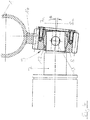
- the Figure 3 shows a cross section through a specific embodiment of the drive device.
- a shaft 7 extends out of a gear housing (not designated) assigned to the transport unit 3.
- the drive pinion 8 is arranged at the protruding end of the shaft 7 and is coupled to the shaft 7 in a rotationally fixed manner about the axis of rotation 7a.
- the pinion 8 also has circumferential spur gear teeth, for example involute teeth, which engage in corresponding teeth on the gear rail 14, which in turn is welded to the underside of the upper running rail 1.
- the pinion 8 is coupled to the shaft 7 via a spherical bearing 9 in such a way that it can pivot in two dimensions relative to this.
- the spherical bearing 9 is formed by the pinion 8 and a socket 12 pushed onto the shaft 7 and secured so that the longitudinal axis 8a of the pinion 8 can pivot by a maximum of 6 ° relative to the axis of rotation 7a of the shaft 7.
- the Figure 5 shows in an exploded view the structure of the coupling between pinion and shaft:
- the pinion 8 is pushed onto the shaft 7, which is mounted in a housing of the transport unit 3 and protrudes from there, and is held there in a rotationally fixed manner about the axis of rotation 7a via the bolt 13 inserted into a bore .
- the two-part pinion 8 has a concave joint surface 11 on its inner surface, which slides on a corresponding convex joint surface 10 formed on the outer circumference of the bushing 12.
- the bush 12 has a transverse bore into which the bolt 13 is pushed and thus holds the bush 12 in a stationary manner on the shaft 7.
- the two-part pinion 8 is held together in the axial direction by means of a screwed disk (not designated) and is thus secured on the bushing 12.
Landscapes
- Engineering & Computer Science (AREA)
- Mechanical Engineering (AREA)
- Transportation (AREA)
- Automation & Control Theory (AREA)
- Structural Engineering (AREA)
- Types And Forms Of Lifts (AREA)
- Management, Administration, Business Operations System, And Electronic Commerce (AREA)
- Machines For Laying And Maintaining Railways (AREA)
Description
- Die Erfindung betrifft ein computerunterstütztes Verfahren zur Konstruktion des Tragwerks eines Treppenschrägaufzugs mit einer Zahnradschiene. Die Erfindung betrifft auch ein entsprechendes Computerprogramm-Speichermedium.
- Aus dem Stand der Technik, beispielsweise der
EP 1 700 812 B1 sind Treppenschrägaufzüge bekannt, deren einen Personensitz umfassende Transporteinheit an zwei übereinanderliegenden und als Rohre ausgestalteten Laufschienen entlang geführt wird. Der räumliche Verlauf dieser Führungsrohre relativ zueinander über die Fahrtstrecke hinweg wird somit zunächst einmal durch die Transporteinheit beziehungsweise deren vordefinierte geometrische Ausgestaltung vorgegeben. Darüber hinaus muss der räumliche Verlauf des Tragwerks auch an die geometrischen Vorgaben des späteren Einsatzortes angepasst werden. Ferner erfolgt der Antrieb solcher Treppenschrägaufzüge durch einen in der Transporteinheit angeordneten Motor, der ein ebenfalls der Transporteinheit zugeordnetes Ritzel antreibt, welches in eine korrespondierende und entlang des Tragwerks verlaufende Zahnradschiene eingreift. Es ist daher leicht vorstellbar, dass der Eingriff des Antriebsritzels in der Zahnradschiene nicht über den gesamten Verlauf der Zahnradschiene hinweg ideal verläuft. So kann es an einzelnen Teilabschnitten des Zahnradschienenverlaufs zu geometrisch bedingten "Fehlstellungen" des Antriebsritzels relativ zur Zahnradschiene kommen, was nicht nur eine ungleichmäßige Belastung und somit Abnutzung sämtlicher Zahnflanken zur Folge hat, sondern auch eine ungewollt hohe Beanspruchung von tragenden Teilen des Treppenlifts. Bisher behalf man sich mit einem ungewöhnlich hohen Spiel im Eingriffs-Ritzel-Zahnradschiene, was die Belastungsproblematik allenfalls abmildert, den ungleichmäßigen Zahneingriff jedoch nicht vermeiden kann. Auch wird, um eine zufriedenstellende Funktion des Treppenlifts, insbesondere einen zufriedenstellenden Eingriff der Paarungs-Ritzel-Zahnradschiene zu gewährleisten, das Treppenlift-Tragwerk manuell auf einen Montagestand gefertigt. So wird der Verlauf der Zahnradschiene an einem der beiden Rohre des Tragwerks gemäß den späteren geometrischen Vorgaben in zahlreichen, teilweise iterativen Schritten manuell festgelegt. Dies erfordert nicht nur viel technischen Know-how und Erfahrung, sondern bringt zwangsläufig auch einen sehr hohen manuellen Fertigungsaufwand mit sich. DieWO 2016/028146 zeigt ein Entwurfsverfahren für einen Treppenschrägaufzug, bei welchem ein optisches Muster auf eine dreidimensionale Struktur aufprojiziert wird, an welcher die Schienenführung des Treppenschrägaufzugs befestigt werden soll. Aus derWO 2013/137733 ist ein computerimplementiertes Verfahren für die Analyse einer Bildsequenz in Realzeit bekannt, bei welcher die räumliche Position, die Beabstandung und der Relativwinkel von und zwischen Objekten bestimmt wird. - Es ist die Aufgabe der vorliegenden Erfindung, den für den Treppenlift-Antrieb notwendigen Eingriff des Antriebritzels in die korrespondierende Zahnradschiene dergestalt zu verbessern, dass die Bauteilbelastung, der damit einhergehende Verschleiß und der Fertigungsaufwand reduziert werden. Diese Aufgabe wird durch den Gegenstand des Anspruchs 1 gelöst. Die Unteransprüche definieren dabei bevorzugte Ausführungsformen der vorliegenden Erfindung.
- Die vorliegende Erfindung stellt ein computerimplementiertes Verfahren zur Konstruktion des Tragwerks eines Treppenschrägaufzugs mit einer ersten und einer zweiten Laufschiene und einer an diesen geführten Transporteinheit bereit, wobei das Verfahren folgende Schritte umfasst:
- Festlegen eines räumlichen Verlaufs der ersten Laufschiene entsprechend den von der Tragwerksinstallation vorgegebenen Rahmenbedingungen;
- Festlegen einer Raumachse entsprechend den von der Tragwerksinstallation vorgegebenen Rahmenbedingungen;
- Festlegen einer geometrischen Ausgestaltung der Transporteinheit;
- Bestimmen eines räumlichen Verlaufs einer an der ersten oder an der zweiten Laufschiene ausgebildeten Zahnradschiene, der zum Eingriff eines Ritzels der zur Raumachse ausgerichteten Transporteinheit an der Zahnradschiene notwendig ist, wobei zur Bestimmung des räumlichen Verlaufs der Zahnradschiene der räumliche Positionsverlauf der entlang der ersten Laufschiene geführten und entlang der Raumachse ausgerichteten Transporteinheit mittels einer dreidimensionalen Modellsimulation simuliert wird, indem ein virtuelles Modell der Transporteinheit an einem virtuellen Modell der ersten Laufschiene entlang geführt wird und das der Transporteinheit zugeordnete Ritzel den räumlichen Verlauf der Zahnradschiene im dreidimensionalen virtuellen Raum aufzeichnet, und wobei bei einer an der zweiten Laufschiene ausgebildeten Zahnradschiene auch der auf Basis des räumlichen Verlaufs der ersten Laufschiene bestimmte räumliche Verlauf der zweiten Laufschiene berücksichtigt wird.
- Erfindungsgemäß wird auch tragwerksseitig der Eingriff Ritzel-Zahnradschiene verbessert. Wie einleitend ebenfalls bereits angesprochen wurde, bringt die Konstruktion und Fertigung der für den Antrieb notwendigen Zahnradschiene einen hohen Fertigungsaufwand mit sich, da die beispielsweise an einer der Tragwerkslaufschienen angeschweißte Zahnradschiene zusammen mit der entsprechenden Laufschiene oftmals in drei Dimensionen gekrümmt ist, allerdings stets ein Eingriff des Antriebsritzels in der Laufschiene sichergestellt werden muss. Gemäß dem erfindungsgemäßen computerimplementierten Verfahren wird zunächst der räumliche Verlauf der ersten Tragwerks-Laufschiene festgelegt und zwar entsprechend den geometrischen Vorgaben des späteren Einbau- bzw. Einsatzortes des Treppenlifts. In diesem Zusammenhang ist es vorstellbar, dass der räumliche Verlauf der ersten Schiene mit Hilfe eines Konstruktionsprogramms an ein virtuelles Modell des späteren Einsatzortes angepasst wird. Es ist jedoch ebenso vorstellbar, dass der räumliche Verlauf der ersten Laufschiene bereits durch deren Fertigung festgelegt wurde, woraufhin dieser für das weitere Konstruktionsverfahren nur noch digitalisiert werden muss. So kann die bereits gefertigte Laufschiene vermessen und die gewonnen Daten für das weitere computerimplementierte Konstruktionsverfahren dem entsprechenden Computer zur Weiterverarbeitung zugeführt werden.
- Beim erfindungsgemäßen Verfahren wird ferner eine Raumachse, also eine Achse im dreidimensionalen Raum relativ zum Verlauf der ersten Schiene festgelegt. An dieser Achse wird die Transporteinheit des Treppenlifts letztendlich ausgerichtet. Anders ausgedrückt legt die Raumachse also die Ausrichtung der Transporteinheit relativ zur ersten Laufschiene fest.
- Zuletzt muss noch die geometrische Ausgestaltung der Transporteinheit bekannt sein, die ja letztendlich nicht nur die für die Führung der Transporteinheit am und entlang beider Laufschienen notwendige Relativposition beider Laufschienen vorgibt, sondern auch die für einen Eingriff des Ritzels an der Zahnradschiene notwendige Relativposition zumindest einer der beiden Laufschienen und der Zahnradschiene vorgibt.
- Die obigen Daten definieren somit die Rahmenbedingungen für den räumlichen Verlauf der Zahnradschiene des Tragwerks, innerhalb welcher ein zufriedenstellender Eingriff des Ritzels an und entlang der Zahnradschiene stattfindet.
- Es wird zur Bestimmung des räumlichen Verlaufs der Zahnradschiene der räumliche Positionsverlauf der an und entlang der ersten Laufschiene geführten und an der Raumachse ausgerichteten Transporteinheit simuliert, und zwar mittels einer dreidimensionalen Modellsimulation, indem ein virtuelles Modell der Transporteinheit an einem virtuellen Modell der ersten Laufschiene mit einem bereits festgelegten räumlichen Verlauf entlang geführt wird, wobei die Transporteinheit darüber hinaus an der bereits ebenfalls festgelegten Raumachse ausgerichtet wird. Zur Ausrichtung der Transporteinheit an der Raumachse ist zu sagen, dass die Transporteinheit bevorzugterweise so an der Raumachse ausgerichtet ist, dass die Hochachse der Transporteinheit, die senkrecht auf die Sitzfläche der Transporteinheit stehen kann, parallel zur vordefinierten Raumachse verläuft. Mit der Simulation der an der Raumachse ausgerichteten und an der ersten Schiene entlang geführten Transporteinheit wird durch die Transporteinheit oder vielmehr das ihr zugeordnete Antriebsritzel selbst der räumliche Verlauf der Zahnradschiene festgelegt beziehungsweise kurvenscheibenartig im dreidimensionalen virtuellen Raum aufgezeichnet.
- Gemäß einer weiteren Ausführungsform der vorliegenden Erfindung umfasst die Simulation des räumlichen Positionsverlaufs der Transporteinheit die Simulation der räumlichen Position zumindest einer, insbesondere aller an zumindest der ersten oder einer zweiten Laufschiene angreifenden Rollen der Transporteinheit. So können mittels Simulation auch die Punkte berücksichtigt werden, an denen die einzelnen Laufrollen der Transporteinheit an den Laufschienen anliegen. Da die Laufrollen durch deren Koppelung an der Transporteinheit in ihrer räumlichen Lage mehr oder weniger stark aneinander gebunden sind, bilden die Kontaktpunkte der einzelnen Rollen weitere Rahmenbedingungen für den Verlauf der Zahnradschiene.
- Im Rahmen der vorliegenden Erfindung ist es möglich, zur Bestimmung des räumlichen Verlaufs der Zahnradschiene für die einzelnen Punkte des Schienenverlaufs sämtliche Raumkoordinaten in einem Arbeitsschritt zu berechnen. Es ist jedoch ebenso vorstellbar, dass die Raumkoordinaten der einzelnen Punkte des Schienenverlaufs getrennt voneinander berechnet werden, wobei es insbesondere vorstellbar ist, dass der horizontale Verlauf getrennt vom vertikalen Verlauf der Zahnradschiene berechnet wird.
- Ferner ist es möglich, zur Bestimmung des räumlichen Verlaufs der Zahnradschiene den Verlauf einer Achse der Schienenverzahnung zu bestimmen, die mit einer Achse der Ritzelverzahnung am Eingriffsort zusammenfällt. Insbesondere kann deren horizontaler Verlauf und deren vertikaler Verlauf getrennt voneinander bestimmt werden.
- Die Richtung der Raumachse, an welcher die Transporteinheit ausgerichtet werden soll, kann sich grundsätzlich über den Verlauf der Lauf- und somit auch der Zahnradschiene verändern. Beispielsweise kann man sich vorstellen, dass die Transporteinheit entlang des gesamten Streckenverlaufs eine gewisse Neigung aufweist, etwa quer zur Fahrtrichtung nach vorne oder nach hinten geneigt. Es kann aber auch vorgesehen sein, dass die Raumachse und somit die Neigung der Transporteinheit sich in bestimmten Streckenabschnitten, etwa in Kurven von deren sonstiger Ausrichtung im übrigen Streckenverlauf unterscheidet. Vorzugsweise ist die Richtung der Raumachse allerdings über die gesamte Fahrtstrecke, also den gesamten Verlauf der Laufschienen konstant, so dass die Transporteinheit beim späteren Einsatz über den gesamten Streckenverlauf an einer einzigen Richtung ausgerichtet ist. So kann die Raumachse parallel zur Richtung der Schwerkraft in der letztendlichen Einbaulage des Treppenlifts ausgerichtet sein. Auf diese Weise wird die Transporteinheit im späteren Einsatz stets in gleicher Weise relativ zum Schwerkraftvektor ausgerichtet sein.
- Vorzugsweise ist es die obere, beispielsweise rohrförmige Laufschiene des Tragwerks, deren räumlicher Verlauf zunächst festgelegt wird, auf dessen Basis dann der räumliche Verlauf der unteren Tragwerks-Laufschiene bestimmt wird. Die Begriffe "oben" und "unten" beziehen sich dabei auf die Einbauposition am Einsatzort. Auch ist es vorzugsweise die erste, obere Laufschiene, an deren Unterseite die Zahnradschiene verläuft und dort etwa mit der Laufschiene verschweißt sein kann.
- Ferner offenbart wird ein Verfahren zur Fertigung des Tragwerks eines Treppenschrägaufzuges mit einer ersten Laufschiene, einer Zahnradschiene und einer an diesen geführten Transporteinheit, mit folgenden Schritten:
- Fertigung, insbesondere Installation der ersten Laufschiene mit einem festgelegten räumlichen Verlauf;
- Durchführung eines wie oben beschriebenen computerimplementierten Konstruktionsverfahrens;
- Fertigung, insbesondere Anbringung der Zahnradschiene mit dem mittels des Konstruktionsverfahrens bestimmten räumlichen Verlauf.
- Wie bereits weiter oben angedeutet, kann zunächst eine erste, vorzugsweise obere Laufschiene mit einem räumlichen Verlauf gefertigt werden, der am für den späteren Einsatzort des Treppenlifts erforderlich ist. Mittels des wie oben beschriebenen Konstruktions- bzw. Simulationsverfahrens kann nach Vermessung dieser Laufschiene der räumliche Verlauf der Zahnradschiene des Tragwerks berechnet werden. Es ist jedoch ebenso vorstellbar, dass der räumliche Verlauf des Tragwerks rein virtuell bestimmt wird. So kann etwa der räumliche Verlauf der ersten Laufschiene unter Zuhilfenahme eines Modells des späteren Einsatzortes festgelegt werden, und sogleich auch mittels der oben beschriebenen Konstruktion bzw. Simulation der räumliche Verlauf der Zahnradschiene bestimmt werden.
- Mithilfe der vorliegenden Erfindung ist der notwendige räumliche Verlauf zumindest der Zahnradschiene bereits vor deren Fertigung genau bekannt und muss somit während der Fertigung nicht mehr zeitaufwändig verändert und angepasst werden.
- Ein weiterer Aspekt der vorliegenden Erfindung betrifft ein Computerprogramm-Speichermedium bzw. einen Datenträger mit einem darauf gespeicherten Programm, das einen Computer zur Durchführung eines oben beschriebenen Konstruktionsverfahrens veranlasst.
- Eine Antriebseinrichtung für einen Treppenschrägaufzug kann einen Motor umfassen, eine drehfest an den Antrieb des Motors gekoppelte Welle, und ein über eine Koppelung drehfest an die Welle gekoppeltes Ritzel, wobei die Koppelung eine Bewegung der Ritzellängsachse relativ zur Wellendrehachse zulässt.
- Mit anderen Worten treibt der in der Transporteinheit befindliche Motor eine ebenfalls der Transporteinheit zugeordnete Welle an, die eine relativ zur Transporteinheit feststehende Drehachse aufweisen kann. Über diese Welle wird letztendlich ein Antriebsritzel angetrieben, welches beispielsweise am abtriebsseitigen Ende dieser Welle angeordnet sein kann. Sofern der Verlauf der Zahnradschiene am Eingriffspunkt des Ritzels stets senkrecht zur Wellendrehachse in einem konstanten Abstand verläuft, die Zahnflanken der Zahnradschiene also stets parallel zu den Zahnflanken des Antriebsritzels stehen und die Höhendifferenz zwischen der Wellendrehachse und der Zahnradschiene konstant bleibt, bringt ein fest auf der Welle angeordnetes Ritzel keine Probleme mit sich. Sobald jedoch, wie es bei Treppenliften oftmals der Fall ist, die Zahnradschiene in drei Dimensionen gekrümmt ist, kommt es zwangsläufig zu unerwünschten Abweichungen im Zahneingriff. Dem begegnet die vorliegende Erfindung damit, dass das Ritzel zwar drehfest mit der Welle verbunden ist, seine Längsachse allerdings relativ zur Wellendrehachse verschwenkbar ist. So können Fehlstellungen, also eine mögliche Nichtparallelität zwischen den korrespondierenden Zahnflanken durch eine Bewegung des Ritzels relativ zur Welle kompensiert werden. Sowohl die Zahnflanken des Ritzels als auch die Zahnflanken der Zahnradschiene werden somit gleichmäßiger belastet und es ist auch möglich, das bisher notwendige Spiel im Zahneingriff erheblich zu verringern. In gleicher Weise können so auch Fehlstellungen kompensiert werden, die durch eine Verkippung der Zahnradstange um deren Längsachse und relativ zur Wellendrehachse zustande kommen.
- Die Welle kann antriebsseitig gelagert sein und erstreckt sich abtriebsseitig über die Lagerung hinaus in Richtung des Ritzels. So kann das Ritzel in einem Endbereich einer einseitig gelagerten Welle angeordnet sein, die sich beispielsweise von einem tragendem Bauteil, etwa von einem Getriebegehäuse aus fort erstreckt und sozusagen auskragt.
- Auch ist es vorstellbar, dass die die Welle und das Ritzel verbindende Koppelung zwei, insbesondere ausschließlich zwei rotatorische Freiheitsgrade zulässt. Wie bereits weiter oben angedeutet wurde, kann mit zwei rotatorischen Freiheitsgraden des Ritzels relativ zur Welle sowohl eine Verkippung der Zahnradschiene um deren Längsachse als auch eine Verkippung der Zahnradschiene senkrecht zur Wellendrehachse kompensiert werden. Sofern die Koppelung ausschließlich zwei rotatorische Freiheitsgrade ermöglicht, ist das Ritzel sowohl in seinen drei translatorischen Freiheitsgraden als auch rotatorisch um die Wellendrehachse relativ zur Welle festgelegt. Es wäre jedoch durchaus vorstellbar, dem Ritzel einen translatorischen Freiheitsgrad entlang der Wellendrehachse zu geben, um etwa mögliche Verschiebungen der Zahnradschienenposition entlang der Wellendrehachse zu kompensieren, sobald die Transporteinheit entlang des Tragwerks bewegt wird.
- Um die Bewegung des Ritzels relativ zur Welle zu ermöglichen, könnte die Koppelung ein elastischen Element umfassen, welche sich bei einer Bewegung der Ritzellängsachse relativ zur Wellendrehachse verformt. Beispielsweise könnte ein aus einem elastischem Kunststoff gefertigtes Zwischenelement zwischen die Welle und das Ritzel eingebracht werden und dort in der Art einer Silentbuchse wirken.
- Alternativ zu einem elastischen Element kann die Koppelung auch ein zumindest zwei rotatorische Freiheitsgrade bereitstellendes Gelenk aufweisen, etwa ein Gelenklager mit zwei korrespondierenden und aufeinander abgleitenden Gelenkflächen aufweisen. Um zwei rotatorische Freiheitsgrade durch ein Gelenklager bereitstellen zu können, muss eine Gelenkfläche zweidimensional konvex und die andere Gelenkfläche zweidimensional konkav gegründet sein. Bevorzugterweise ist dabei die wellenseitige Gelenkfläche konvex und die ritzelseitige Gelenkfläche konkav gekrümmt.
- Auch kann zumindest eine Gelenkfläche als Kugelzone ausgebildet sein, welche die Wellendrehachse beziehungsweise die Ritzellängsachse rotationssymmetrisch umläuft.
- Dabei wäre es grundsätzlich möglich, die wellenseitige Gelenkfläche des Gelenks direkt auf der Oberfläche der Welle auszubilden, also etwa aufzudrehen. Andererseits ist es ebenso vorstellbar, die wellenseitige Gelenkfläche mittels einer Buchse bereitzustellen, welche die Welle radial umläuft und beispielsweise auf diese aufgeschoben oder gar aufgepresst werden kann.
- Um eine solche aufgeschobene Buchse auf der Welle zu sichern, kann ein Bolzen vorgesehen sein, der die Welle senkrecht zu deren Drehachse und auch die Buchse zumindest teilweise durchdringt. Dieser Bolzen kann auch dazu genutzt werden, gleichzeitig auch das Ritzel drehfest auf der Welle zu halten, so dass dieses unter Beibehaltung seiner zwei Freiheitsgrade mit der Welle mitdreht.
- Die Erfindung wird nachfolgend anhand der Zeichnungen an Ausführungsbeispielen näher erläutert. Die hierin beschriebenen Merkmale können einzeln sowie in jedweder sinnvollen Kombination von der vorliegenden Erfindung umfasst werden. Es zeigen:
- Figur 1
- einen Treppenschrägaufzug mit einem zwei Laufschienen umfassenden Tragwerk,
- Figur 2
- eine zur Führung an und entlang zwei Laufschienen ausgestalteten Transporteinheit mit einem rückwärtig auskragenden Antriebsritzel;
- Figur 3
- Schnittansicht durch die Antriebseinrichtung;
- Figur 4
- vergrößerte Schnittansicht durch die Antriebseinrichtung;
- Figur 5
- Explosionsansicht der Koppelung zwischen Ritzel und Welle.
- In der
Figur 1 ist ein Treppenschrägaufzug/Treppenlift gezeigt, dessen Transporteinheit 3 an zwei übereinanderliegenden rohrförmigen Laufschienen 1 und 2 derart geführt wird, dass diese beim Verfahren entlang der Schienen 1 und 2 stets zum des Schwerkraftvektor G ausgerichtet ist. Der Sitz der Transporteinheit 3 nimmt somit zu jeder Zeit eine "lotrechte" Lage ein und wird folglich nur um den Vektor G herum verdreht. Die obere Laufschiene 1 trägt an ihrer Unterseite, wie durch dieFiguren 3 und4 deutlich wird, eine Zahnradschiene 14. - Die
Figur 2 zeigt eine entsprechende Transporteinheit 3, auf deren Rückseite mehrere zumindest teilweise relativ zur Transporteinheit 3 positionsvariable Laufrollen 4 und 5 gelagert sind, mittels derer die Transporteinheit 3 sowohl an den Verlauf der oberen Laufschiene 1 als auch an den Verlauf der unteren Laufschiene 2 gekoppelt ist. Ferner ist in derFigur 2 die zentrale Faser bzw. Mittelachse 6 der zweiten, unteren Laufschiene 2 zu sehen, deren räumlicher Verlauf zur oberen Laufschiene 1 ebenso mittels des erfindungsgemäßen Konstruktionsverfahrens berechnet werden kann wie der Verlauf der Zahnradschiene 14 relativ zur oberen Laufschiene 1, so dass die Transporteinheit 3 entlang des Schienenverlaufs stets ihre lotrechte Ausrichtung beibehält, und zudem aus stets der Eingriff des Ritzels 8 in die Zahnradschiene 14 gewährleistet ist. - Die
Figur 3 zeigt einen Querschnitt durch eine spezifische Ausführungsform der Antriebseinrichtung. Bei dieser erstreckt sich aus einem der Transporteinheit 3 zugeordneten Getriebegehäuse (nicht bezeichnet) eine Welle 7. Diese ist innerhalb des Getriebegehäuses gelagert und dreht sich um die relativ zur Transporteinheit 3 festgelegte Drehachse 7a. Am auskragenden Ende der Welle 7 ist das Antriebsritzel 8 angeordnet und um die Rotationsachse 7a drehfest an die Welle 7 gekoppelt. Das Ritzel 8 weist ferner umfänglich eine Stirnradverzahnung, beispielsweise eine Evolventenverzahnung auf, die in eine korrespondierende Verzahnung der Zahnradschiene 14 eingreift, die wiederrum an der Unterseite der oberen Laufschiene 1 an dieser angeschweißt ist. - Aus der
Figur 4 , einer gegenüber derFigur 3 vergrößerten Schnittansicht, wird die Funktionsweise der Antriebseinrichtung deutlich: An dem in derFigur 4 gezeigten Angriffsort weicht die Zahnradschiene 14 von ihrer in derFigur 3 gezeigten und mittig unterhalt der Laufschiene 1 gelegenen Position ab, so dass deren Zahnflanken nicht mehr parallel zur Drehachse 7a der Welle 7 verlaufen. Ein koaxial mit der Welle 7 starr verbundenes Ritzel 8 könnte somit nicht mehr in idealer Weise in die Verzahnung der Zahnradschiene 14 eingreifen, so dass nicht nur die Verzahnungen einer erhöhten Belastung und somit einem erhöhten Verschleiß unterworfen sind, sondern auch die für den Antrieb und die Führung der Transporteinheit 3 entlang des Tragwerks vorgesehenen Bauteile. - Bei der Antriebseinrichtung hingegen ist das Ritzel 8 über ein Gelenklager 9 so an die Welle 7 gekoppelt, dass es relativ zu dieser in zwei Dimensionen verschwenken kann. Das Gelenklager 9 wird durch das Ritzel 8 und eine auf die Welle 7 aufgeschobene und gesicherte Buchse 12 gebildet, so dass die Längsachse 8a des Ritzels 8 um etwa maximal 6° relativ zur Drehachse 7a der Welle 7 verschwenken kann.
- Die
Figur 5 zeigt in einer Explosionsansicht den Aufbau der Koppelung zwischen Ritzel und Welle: Auf die in einem Gehäuse der Transporteinheit 3 gelagerte und von dort aus auskragende Welle 7 wird das Ritzel 8 aufgeschoben und dort über den in eine Bohrung eingeschobenen Bolzen 13 drehfest um die Drehachse 7a gehalten. Um ein zweidimensionales Verschwenken des Ritzels 8 relativ zur Welle 7 zu ermöglichen, weist das zweiteilige Ritzel 8 an seiner Innenfläche eine konkave Gelenkfläche 11 auf, die an einer korrespondierenden, am äußeren Umfang der Buchse 12 ausgebildeten konvexen Gelenkfläche 10 abgleitet. Die Buchse 12 weist eine Querbohrung auf, in welche der Bolzen 13 eingeschoben wird und so die Buchse 12 ortsfest an der Welle 7 hält. Das zweiteilige Ritzel 8 wird mittels einer verschraubten und nicht bezeichneten Scheibe in axialer Richtung zusammengehalten und somit auf der Buchse 12 gesichert.
Claims (3)
- Computerimplementiertes Verfahren zur Konstruktion des Tragwerks eines Treppenschrägaufzugs mit einer ersten und einer zweiten Laufschiene (1, 2) und einer an diesen geführten Transporteinheit (3), wobei das Verfahren folgende Schritte umfasst:- Festlegen eines räumlichen Verlaufs der ersten Laufschiene (1) entsprechend den von der Tragwerksinstallation vorgegebenen Rahmenbedingungen;- Festlegen einer Raumachse (G) entsprechend den von der Tragwerksinstallation vorgegebenen Rahmenbedingungen;- Festlegen einer geometrischen Ausgestaltung der Transporteinheit (3);- Bestimmen eines räumlichen Verlaufs einer an der ersten (1) oder an der zweiten (2) Laufschiene ausgebildeten Zahnradschiene (14), der zum Eingriff eines Ritzels (8) der zur Raumachse (G) ausgerichteten Transporteinheit (3) an der Zahnradschiene (14) notwendig ist, wobei zur Bestimmung des räumlichen Verlaufs der Zahnradschiene (14) der räumliche Positionsverlauf der entlang der ersten Laufschiene (1) geführten und entlang der Raumachse (G) ausgerichteten Transporteinheit (3) mittels einer dreidimensionalen Modellsimulation simuliert wird, indem ein virtuelles Modell der Transporteinheit (3) an einem virtuellen Modell der ersten Laufschiene (1) entlang geführt wird und das der Transporteinheit (3) zugeordnete Ritzel (8) den räumlichen Verlauf der Zahnradschiene (14) im dreidimensionalen virtuellen Raum aufzeichnet, und wobei bei einer an der zweiten Laufschiene (2) ausgebildeten Zahnradschiene (14) auch der auf Basis des räumlichen Verlaufs der ersten Laufschiene (1) bestimmte räumliche Verlauf der zweiten Laufschiene (2) berücksichtigt wird.
- Verfahren gemäß Anspruch 1, wobei bei der Bestimmung des räumlichen Verlaufs der Zahnradschiene (14) eine mögliche Bewegung des Ritzels (8) einer Transporteinheit (3) berücksichtigt wird, welches über ein zumindest zwei rotatorische Freiheitsgrade bereitstellendes Gelenk (9) drehfest an eine Welle (7) gekoppelt ist, die drehfest an den Abtrieb des Motors der Transporteinheit (3) gekoppelt ist.
- Computerprogramm-Speichermedium mit einem darauf gespeicherten Programm, welches, wenn es auf einem Computer-Prozessor ausgeführt wird oder im Speicher eines Computers geladen ist, den Computer dazu veranlasst, ein Verfahren gemäß einem der Ansprüche 1 oder 2 durchzuführen.
Priority Applications (4)
| Application Number | Priority Date | Filing Date | Title |
|---|---|---|---|
| PL17197908T PL3293136T3 (pl) | 2016-03-30 | 2016-06-28 | Wspomagana komputerowo konstrukcja listwy zębatej windy schodowej |
| RS20211480A RS62638B1 (sr) | 2016-03-30 | 2016-06-28 | Računarski vođeno projektovanje konstrukcije nazubljene šine stepenišnog lifta |
| SI201631376T SI3293136T1 (sl) | 2016-03-30 | 2016-06-28 | Računalniško podprta konstrukcija zobate tirnice stopniščnega dvigala |
| HRP20211892TT HRP20211892T1 (hr) | 2016-03-30 | 2016-06-28 | Računalno vođeno projektiranje konstrukcije nazubljene šine stubišnog lifta |
Applications Claiming Priority (2)
| Application Number | Priority Date | Filing Date | Title |
|---|---|---|---|
| EP16162732.8A EP3225580B1 (de) | 2016-03-30 | 2016-03-30 | Simulationsunterstützte treppenlift-konstruktion |
| EP16176744.7A EP3225581B1 (de) | 2016-03-30 | 2016-06-28 | Treppenlift mit einem beweglichen antriebsritzel |
Related Parent Applications (2)
| Application Number | Title | Priority Date | Filing Date |
|---|---|---|---|
| EP16176744.7A Division-Into EP3225581B1 (de) | 2016-03-30 | 2016-06-28 | Treppenlift mit einem beweglichen antriebsritzel |
| EP16176744.7A Division EP3225581B1 (de) | 2016-03-30 | 2016-06-28 | Treppenlift mit einem beweglichen antriebsritzel |
Publications (2)
| Publication Number | Publication Date |
|---|---|
| EP3293136A1 EP3293136A1 (de) | 2018-03-14 |
| EP3293136B1 true EP3293136B1 (de) | 2021-09-29 |
Family
ID=55699405
Family Applications (3)
| Application Number | Title | Priority Date | Filing Date |
|---|---|---|---|
| EP16162732.8A Active EP3225580B1 (de) | 2016-03-30 | 2016-03-30 | Simulationsunterstützte treppenlift-konstruktion |
| EP16176744.7A Active EP3225581B1 (de) | 2016-03-30 | 2016-06-28 | Treppenlift mit einem beweglichen antriebsritzel |
| EP17197908.1A Active EP3293136B1 (de) | 2016-03-30 | 2016-06-28 | Computerunterstützte konstruktion einer zahnradschiene eines treppenliftes |
Family Applications Before (2)
| Application Number | Title | Priority Date | Filing Date |
|---|---|---|---|
| EP16162732.8A Active EP3225580B1 (de) | 2016-03-30 | 2016-03-30 | Simulationsunterstützte treppenlift-konstruktion |
| EP16176744.7A Active EP3225581B1 (de) | 2016-03-30 | 2016-06-28 | Treppenlift mit einem beweglichen antriebsritzel |
Country Status (10)
| Country | Link |
|---|---|
| EP (3) | EP3225580B1 (de) |
| DK (1) | DK3225580T3 (de) |
| ES (2) | ES2670474T3 (de) |
| HR (2) | HRP20211892T1 (de) |
| HU (2) | HUE037864T2 (de) |
| NO (1) | NO3225580T3 (de) |
| PL (2) | PL3225580T3 (de) |
| PT (2) | PT3225580T (de) |
| RS (2) | RS57184B1 (de) |
| SI (2) | SI3225580T1 (de) |
Families Citing this family (4)
| Publication number | Priority date | Publication date | Assignee | Title |
|---|---|---|---|---|
| EP3466858A1 (de) * | 2017-10-04 | 2019-04-10 | thyssenkrupp Stairlifts B.V. | Verfahren zur planung einer hebebühne |
| CN111547602A (zh) * | 2020-05-12 | 2020-08-18 | 赵金甲 | 一种楼道升降系统 |
| CN112744668B (zh) * | 2020-12-30 | 2022-10-04 | 王丛乐 | 一种转弯轨道、转弯联动机构、爬楼装置及爬楼系统 |
| GB2621860A (en) * | 2022-08-24 | 2024-02-28 | Stannah Stairlifts Ltd | Improvements in or relating to stairlifts |
Family Cites Families (8)
| Publication number | Priority date | Publication date | Assignee | Title |
|---|---|---|---|---|
| DE3819522A1 (de) * | 1988-06-08 | 1989-12-14 | Kleindienst Gmbh | Treppenlift |
| JP4275246B2 (ja) * | 1998-11-02 | 2009-06-10 | クマリフト株式会社 | いす式階段昇降装置 |
| RO121336B1 (ro) | 2005-03-07 | 2007-03-30 | Teofil Nuţu Andreş | Stabilizator pentru lifturi de trepte |
| WO2009072917A1 (de) * | 2007-12-03 | 2009-06-11 | Mihai Petrachioiu | Bivalentes mechanismus zur verticalstabilisierung eines treppenlifts |
| FR2927164B1 (fr) * | 2008-02-01 | 2010-02-12 | Jean Leon Elevation | Dispositif de mesure d'un profil de rampe d'escalier |
| JP2010070329A (ja) * | 2008-09-19 | 2010-04-02 | Kuma Lift Gijutsu Kenkyusho:Kk | 椅子式階段昇降機の駆動・ガイド機構 |
| NL2008490C2 (nl) * | 2012-03-15 | 2013-09-18 | Ooms Otto Bv | Werkwijze, inrichting en computerprogramma voor het extraheren van informatie over een of meerdere ruimtelijke objecten. |
| NL2013355B1 (en) * | 2014-08-22 | 2016-09-23 | Handicare Stairlifts B V | Method and system for designing a stair lift rail assembly. |
-
2016
- 2016-03-30 NO NO16162732A patent/NO3225580T3/no unknown
- 2016-03-30 SI SI201630039T patent/SI3225580T1/en unknown
- 2016-03-30 DK DK16162732.8T patent/DK3225580T3/en active
- 2016-03-30 EP EP16162732.8A patent/EP3225580B1/de active Active
- 2016-03-30 RS RS20180463A patent/RS57184B1/sr unknown
- 2016-03-30 ES ES16162732.8T patent/ES2670474T3/es active Active
- 2016-03-30 PT PT161627328T patent/PT3225580T/pt unknown
- 2016-03-30 HU HUE16162732A patent/HUE037864T2/hu unknown
- 2016-03-30 PL PL16162732T patent/PL3225580T3/pl unknown
- 2016-06-28 RS RS20211480A patent/RS62638B1/sr unknown
- 2016-06-28 PT PT171979081T patent/PT3293136T/pt unknown
- 2016-06-28 EP EP16176744.7A patent/EP3225581B1/de active Active
- 2016-06-28 PL PL17197908T patent/PL3293136T3/pl unknown
- 2016-06-28 HU HUE17197908A patent/HUE056234T2/hu unknown
- 2016-06-28 HR HRP20211892TT patent/HRP20211892T1/hr unknown
- 2016-06-28 EP EP17197908.1A patent/EP3293136B1/de active Active
- 2016-06-28 SI SI201631376T patent/SI3293136T1/sl unknown
- 2016-06-28 ES ES17197908T patent/ES2899918T3/es active Active
-
2018
- 2018-05-28 HR HRP20180843TT patent/HRP20180843T1/hr unknown
Also Published As
| Publication number | Publication date |
|---|---|
| HRP20180843T1 (hr) | 2018-06-29 |
| PL3225580T3 (pl) | 2018-10-31 |
| HUE037864T2 (hu) | 2018-09-28 |
| EP3225580A1 (de) | 2017-10-04 |
| PT3293136T (pt) | 2021-11-05 |
| DK3225580T3 (en) | 2018-05-07 |
| SI3225580T1 (en) | 2018-06-29 |
| EP3225581B1 (de) | 2019-06-19 |
| ES2670474T3 (es) | 2018-05-30 |
| ES2899918T3 (es) | 2022-03-15 |
| RS62638B1 (sr) | 2021-12-31 |
| PL3293136T3 (pl) | 2022-02-07 |
| EP3225581A1 (de) | 2017-10-04 |
| EP3225580B1 (de) | 2018-03-07 |
| EP3293136A1 (de) | 2018-03-14 |
| HRP20211892T1 (hr) | 2022-03-04 |
| PT3225580T (pt) | 2018-05-10 |
| RS57184B1 (sr) | 2018-07-31 |
| NO3225580T3 (de) | 2018-08-04 |
| SI3293136T1 (sl) | 2021-12-31 |
| HUE056234T2 (hu) | 2022-02-28 |
Similar Documents
| Publication | Publication Date | Title |
|---|---|---|
| EP2337704B1 (de) | Untergestell eines kraftfahrzeugsitzes mit zwei schienenpaaren, schwingen und einem sitzträger | |
| EP0096803B1 (de) | Sitzschiene | |
| EP2815681B1 (de) | Verstellmechanik zur verstellung von beweglichen möbelteilen | |
| EP3049307A1 (de) | Schiebetürmodul/schwenkschiebetürmodul mit fliegender lagerung einer zahnstange eines zahnstangenantriebs | |
| EP2869947B1 (de) | Verfahren zur herstellung eines verbindungselements zur übertragung von drehbewegungen sowie dadurch hergestelltes verbindungselement | |
| EP3293136A1 (de) | Computerunterstützte konstruktion einer zahnradschiene eines treppenliftes | |
| DE3409582A1 (de) | Vorrichtung zur laengsverstellung eines sitzes | |
| DE2659308A1 (de) | Hoehenverstellbarer sitz, insbesondere kraftfahrzeugsitz | |
| EP2520827B1 (de) | Hebevorrichtung zum vertikalen Anheben von Lasten | |
| EP2048022B1 (de) | Fahrzeugsitz, insbesondere Kraftfahrzeugsitz | |
| EP3807023A1 (de) | Kaltwalzmaschine und verfahren zur erzeugung eines profils an einem werkstück | |
| DE3246564A1 (de) | Sitz, insbesondere kraftfahrzeugsitz | |
| AT398113B (de) | Drehblock für ein fahrzeug zur durchführung von hoch gelegenen arbeiten | |
| EP3861240B1 (de) | Abdeckvorrichtung für eine maschinenkabine | |
| WO2011124453A1 (de) | Vorrichtung zur neigungsverstellung einer frontblende | |
| DE112022003418B4 (de) | Gleitblock-baugruppe mit kugelbuchsenlager | |
| EP2369958B1 (de) | Doppelantrieb für möbel | |
| DE202004006666U1 (de) | Anhängerkupplung | |
| EP3392080A1 (de) | Höhenverstelleinrichtung eines kraftfahrzeugsitzes sowie verfahren zur herstellung einer derartigen höhenverstelleinrichtung | |
| DE202008016051U1 (de) | Doppelantrieb für Möbel | |
| DE102010003718A1 (de) | Verstellvorrichtung zur Sitzhöhen-oder Sitzneigungsverstellung eines Fahrzeugsitzes | |
| EP3572056B1 (de) | Tragenlagerungseinrichtung | |
| DE19547432C2 (de) | Fensterheber | |
| EP3771617B1 (de) | Deichsel für ein flurförderzeug | |
| WO2016016064A1 (de) | Spielreduzierter höhenversteller eines fahrzeugsitzes |
Legal Events
| Date | Code | Title | Description |
|---|---|---|---|
| REG | Reference to a national code |
Ref country code: HR Ref legal event code: TUEP Ref document number: P20211892 Country of ref document: HR |
|
| PUAI | Public reference made under article 153(3) epc to a published international application that has entered the european phase |
Free format text: ORIGINAL CODE: 0009012 |
|
| STAA | Information on the status of an ep patent application or granted ep patent |
Free format text: STATUS: REQUEST FOR EXAMINATION WAS MADE |
|
| 17P | Request for examination filed |
Effective date: 20171024 |
|
| AC | Divisional application: reference to earlier application |
Ref document number: 3225581 Country of ref document: EP Kind code of ref document: P |
|
| AK | Designated contracting states |
Kind code of ref document: A1 Designated state(s): AL AT BE BG CH CY CZ DE DK EE ES FI FR GB GR HR HU IE IS IT LI LT LU LV MC MK MT NL NO PL PT RO RS SE SI SK SM TR |
|
| STAA | Information on the status of an ep patent application or granted ep patent |
Free format text: STATUS: EXAMINATION IS IN PROGRESS |
|
| 17Q | First examination report despatched |
Effective date: 20190123 |
|
| GRAP | Despatch of communication of intention to grant a patent |
Free format text: ORIGINAL CODE: EPIDOSNIGR1 |
|
| STAA | Information on the status of an ep patent application or granted ep patent |
Free format text: STATUS: GRANT OF PATENT IS INTENDED |
|
| GRAJ | Information related to disapproval of communication of intention to grant by the applicant or resumption of examination proceedings by the epo deleted |
Free format text: ORIGINAL CODE: EPIDOSDIGR1 |
|
| STAA | Information on the status of an ep patent application or granted ep patent |
Free format text: STATUS: EXAMINATION IS IN PROGRESS |
|
| INTG | Intention to grant announced |
Effective date: 20210215 |
|
| INTC | Intention to grant announced (deleted) | ||
| GRAP | Despatch of communication of intention to grant a patent |
Free format text: ORIGINAL CODE: EPIDOSNIGR1 |
|
| STAA | Information on the status of an ep patent application or granted ep patent |
Free format text: STATUS: GRANT OF PATENT IS INTENDED |
|
| GRAJ | Information related to disapproval of communication of intention to grant by the applicant or resumption of examination proceedings by the epo deleted |
Free format text: ORIGINAL CODE: EPIDOSDIGR1 |
|
| GRAP | Despatch of communication of intention to grant a patent |
Free format text: ORIGINAL CODE: EPIDOSNIGR1 |
|
| INTG | Intention to grant announced |
Effective date: 20210412 |
|
| INTG | Intention to grant announced |
Effective date: 20210415 |
|
| INTG | Intention to grant announced |
Effective date: 20210428 |
|
| GRAS | Grant fee paid |
Free format text: ORIGINAL CODE: EPIDOSNIGR3 |
|
| GRAA | (expected) grant |
Free format text: ORIGINAL CODE: 0009210 |
|
| STAA | Information on the status of an ep patent application or granted ep patent |
Free format text: STATUS: THE PATENT HAS BEEN GRANTED |
|
| AC | Divisional application: reference to earlier application |
Ref document number: 3225581 Country of ref document: EP Kind code of ref document: P |
|
| AK | Designated contracting states |
Kind code of ref document: B1 Designated state(s): AL AT BE BG CH CY CZ DE DK EE ES FI FR GB GR HR HU IE IS IT LI LT LU LV MC MK MT NL NO PL PT RO RS SE SI SK SM TR |
|
| REG | Reference to a national code |
Ref country code: GB Ref legal event code: FG4D Free format text: NOT ENGLISH |
|
| REG | Reference to a national code |
Ref country code: DE Ref legal event code: R096 Ref document number: 502016013932 Country of ref document: DE |
|
| REG | Reference to a national code |
Ref country code: CH Ref legal event code: EP Ref country code: AT Ref legal event code: REF Ref document number: 1434040 Country of ref document: AT Kind code of ref document: T Effective date: 20211015 |
|
| REG | Reference to a national code |
Ref country code: IE Ref legal event code: FG4D Free format text: LANGUAGE OF EP DOCUMENT: GERMAN |
|
| REG | Reference to a national code |
Ref country code: PT Ref legal event code: SC4A Ref document number: 3293136 Country of ref document: PT Date of ref document: 20211105 Kind code of ref document: T Free format text: AVAILABILITY OF NATIONAL TRANSLATION Effective date: 20211028 |
|
| REG | Reference to a national code |
Ref country code: NL Ref legal event code: FP |
|
| REG | Reference to a national code |
Ref country code: DK Ref legal event code: T3 Effective date: 20211124 |
|
| REG | Reference to a national code |
Ref country code: GR Ref legal event code: EP Ref document number: 20210402813 Country of ref document: GR Effective date: 20211111 |
|
| REG | Reference to a national code |
Ref country code: SE Ref legal event code: TRGR |
|
| REG | Reference to a national code |
Ref country code: LT Ref legal event code: MG9D |
|
| PG25 | Lapsed in a contracting state [announced via postgrant information from national office to epo] |
Ref country code: FI Free format text: LAPSE BECAUSE OF FAILURE TO SUBMIT A TRANSLATION OF THE DESCRIPTION OR TO PAY THE FEE WITHIN THE PRESCRIBED TIME-LIMIT Effective date: 20210929 Ref country code: LT Free format text: LAPSE BECAUSE OF FAILURE TO SUBMIT A TRANSLATION OF THE DESCRIPTION OR TO PAY THE FEE WITHIN THE PRESCRIBED TIME-LIMIT Effective date: 20210929 Ref country code: BG Free format text: LAPSE BECAUSE OF FAILURE TO SUBMIT A TRANSLATION OF THE DESCRIPTION OR TO PAY THE FEE WITHIN THE PRESCRIBED TIME-LIMIT Effective date: 20211229 |
|
| REG | Reference to a national code |
Ref country code: SK Ref legal event code: T3 Ref document number: E 38874 Country of ref document: SK |
|
| PG25 | Lapsed in a contracting state [announced via postgrant information from national office to epo] |
Ref country code: LV Free format text: LAPSE BECAUSE OF FAILURE TO SUBMIT A TRANSLATION OF THE DESCRIPTION OR TO PAY THE FEE WITHIN THE PRESCRIBED TIME-LIMIT Effective date: 20210929 |
|
| REG | Reference to a national code |
Ref country code: HU Ref legal event code: AG4A Ref document number: E056234 Country of ref document: HU |
|
| REG | Reference to a national code |
Ref country code: HR Ref legal event code: T1PR Ref document number: P20211892 Country of ref document: HR |
|
| REG | Reference to a national code |
Ref country code: NO Ref legal event code: T2 Effective date: 20210929 |
|
| REG | Reference to a national code |
Ref country code: ES Ref legal event code: FG2A Ref document number: 2899918 Country of ref document: ES Kind code of ref document: T3 Effective date: 20220315 |
|
| PG25 | Lapsed in a contracting state [announced via postgrant information from national office to epo] |
Ref country code: IS Free format text: LAPSE BECAUSE OF FAILURE TO SUBMIT A TRANSLATION OF THE DESCRIPTION OR TO PAY THE FEE WITHIN THE PRESCRIBED TIME-LIMIT Effective date: 20220129 Ref country code: EE Free format text: LAPSE BECAUSE OF FAILURE TO SUBMIT A TRANSLATION OF THE DESCRIPTION OR TO PAY THE FEE WITHIN THE PRESCRIBED TIME-LIMIT Effective date: 20210929 Ref country code: AL Free format text: LAPSE BECAUSE OF FAILURE TO SUBMIT A TRANSLATION OF THE DESCRIPTION OR TO PAY THE FEE WITHIN THE PRESCRIBED TIME-LIMIT Effective date: 20210929 |
|
| REG | Reference to a national code |
Ref country code: DE Ref legal event code: R097 Ref document number: 502016013932 Country of ref document: DE |
|
| PLBE | No opposition filed within time limit |
Free format text: ORIGINAL CODE: 0009261 |
|
| REG | Reference to a national code |
Ref country code: HR Ref legal event code: ODRP Ref document number: P20211892 Country of ref document: HR Payment date: 20220623 Year of fee payment: 7 |
|
| STAA | Information on the status of an ep patent application or granted ep patent |
Free format text: STATUS: NO OPPOSITION FILED WITHIN TIME LIMIT |
|
| 26N | No opposition filed |
Effective date: 20220630 |
|
| PG25 | Lapsed in a contracting state [announced via postgrant information from national office to epo] |
Ref country code: RS Free format text: LAPSE BECAUSE OF NON-PAYMENT OF DUE FEES Effective date: 20220628 Ref country code: MC Free format text: LAPSE BECAUSE OF FAILURE TO SUBMIT A TRANSLATION OF THE DESCRIPTION OR TO PAY THE FEE WITHIN THE PRESCRIBED TIME-LIMIT Effective date: 20210929 |
|
| REG | Reference to a national code |
Ref country code: CH Ref legal event code: PL |
|
| REG | Reference to a national code |
Ref country code: SI Ref legal event code: KO00 Effective date: 20230215 |
|
| PG25 | Lapsed in a contracting state [announced via postgrant information from national office to epo] |
Ref country code: LU Free format text: LAPSE BECAUSE OF NON-PAYMENT OF DUE FEES Effective date: 20220628 Ref country code: LI Free format text: LAPSE BECAUSE OF NON-PAYMENT OF DUE FEES Effective date: 20220630 Ref country code: IE Free format text: LAPSE BECAUSE OF NON-PAYMENT OF DUE FEES Effective date: 20220628 Ref country code: CH Free format text: LAPSE BECAUSE OF NON-PAYMENT OF DUE FEES Effective date: 20220630 |
|
| PG25 | Lapsed in a contracting state [announced via postgrant information from national office to epo] |
Ref country code: SI Free format text: LAPSE BECAUSE OF NON-PAYMENT OF DUE FEES Effective date: 20220629 |
|
| P01 | Opt-out of the competence of the unified patent court (upc) registered |
Effective date: 20230425 |
|
| REG | Reference to a national code |
Ref country code: HR Ref legal event code: ODRP Ref document number: P20211892 Country of ref document: HR Payment date: 20230616 Year of fee payment: 8 |
|
| REG | Reference to a national code |
Ref country code: SK Ref legal event code: MM4A Ref document number: E 38874 Country of ref document: SK Effective date: 20220628 |
|
| PG25 | Lapsed in a contracting state [announced via postgrant information from national office to epo] |
Ref country code: SK Free format text: LAPSE BECAUSE OF NON-PAYMENT OF DUE FEES Effective date: 20220628 |
|
| PG25 | Lapsed in a contracting state [announced via postgrant information from national office to epo] |
Ref country code: SM Free format text: LAPSE BECAUSE OF FAILURE TO SUBMIT A TRANSLATION OF THE DESCRIPTION OR TO PAY THE FEE WITHIN THE PRESCRIBED TIME-LIMIT Effective date: 20210929 Ref country code: MK Free format text: LAPSE BECAUSE OF FAILURE TO SUBMIT A TRANSLATION OF THE DESCRIPTION OR TO PAY THE FEE WITHIN THE PRESCRIBED TIME-LIMIT Effective date: 20210929 Ref country code: CY Free format text: LAPSE BECAUSE OF FAILURE TO SUBMIT A TRANSLATION OF THE DESCRIPTION OR TO PAY THE FEE WITHIN THE PRESCRIBED TIME-LIMIT Effective date: 20210929 |
|
| REG | Reference to a national code |
Ref country code: HR Ref legal event code: ODRP Ref document number: P20211892 Country of ref document: HR Payment date: 20240620 Year of fee payment: 9 |
|
| PGFP | Annual fee paid to national office [announced via postgrant information from national office to epo] |
Ref country code: GB Payment date: 20240621 Year of fee payment: 9 |
|
| PGFP | Annual fee paid to national office [announced via postgrant information from national office to epo] |
Ref country code: DK Payment date: 20240621 Year of fee payment: 9 |
|
| PGFP | Annual fee paid to national office [announced via postgrant information from national office to epo] |
Ref country code: GR Payment date: 20240613 Year of fee payment: 9 |
|
| PGFP | Annual fee paid to national office [announced via postgrant information from national office to epo] |
Ref country code: HR Payment date: 20240620 Year of fee payment: 9 Ref country code: NL Payment date: 20240619 Year of fee payment: 9 |
|
| PGFP | Annual fee paid to national office [announced via postgrant information from national office to epo] |
Ref country code: CZ Payment date: 20240620 Year of fee payment: 9 Ref country code: AT Payment date: 20240620 Year of fee payment: 9 |
|
| PGFP | Annual fee paid to national office [announced via postgrant information from national office to epo] |
Ref country code: NO Payment date: 20240621 Year of fee payment: 9 Ref country code: FR Payment date: 20240628 Year of fee payment: 9 |
|
| PGFP | Annual fee paid to national office [announced via postgrant information from national office to epo] |
Ref country code: PL Payment date: 20240620 Year of fee payment: 9 Ref country code: PT Payment date: 20240620 Year of fee payment: 9 |
|
| PGFP | Annual fee paid to national office [announced via postgrant information from national office to epo] |
Ref country code: SE Payment date: 20240619 Year of fee payment: 9 Ref country code: HU Payment date: 20240621 Year of fee payment: 9 Ref country code: BE Payment date: 20240619 Year of fee payment: 9 |
|
| PG25 | Lapsed in a contracting state [announced via postgrant information from national office to epo] |
Ref country code: MT Free format text: LAPSE BECAUSE OF FAILURE TO SUBMIT A TRANSLATION OF THE DESCRIPTION OR TO PAY THE FEE WITHIN THE PRESCRIBED TIME-LIMIT Effective date: 20210929 |
|
| PGFP | Annual fee paid to national office [announced via postgrant information from national office to epo] |
Ref country code: IT Payment date: 20240625 Year of fee payment: 9 |
|
| PGFP | Annual fee paid to national office [announced via postgrant information from national office to epo] |
Ref country code: ES Payment date: 20240731 Year of fee payment: 9 |
|
| PGFP | Annual fee paid to national office [announced via postgrant information from national office to epo] |
Ref country code: DE Payment date: 20250618 Year of fee payment: 10 |
|
| PGFP | Annual fee paid to national office [announced via postgrant information from national office to epo] |
Ref country code: RO Payment date: 20250624 Year of fee payment: 10 |
|
| PG25 | Lapsed in a contracting state [announced via postgrant information from national office to epo] |
Ref country code: TR Free format text: LAPSE BECAUSE OF FAILURE TO SUBMIT A TRANSLATION OF THE DESCRIPTION OR TO PAY THE FEE WITHIN THE PRESCRIBED TIME-LIMIT Effective date: 20210929 |
|
| REG | Reference to a national code |
Ref country code: HR Ref legal event code: PBON Ref document number: P20211892 Country of ref document: HR Effective date: 20250628 |
|
| PG25 | Lapsed in a contracting state [announced via postgrant information from national office to epo] |
Ref country code: PT Free format text: LAPSE BECAUSE OF NON-PAYMENT OF DUE FEES Effective date: 20251229 |
|
| PG25 | Lapsed in a contracting state [announced via postgrant information from national office to epo] |
Ref country code: CZ Free format text: LAPSE BECAUSE OF NON-PAYMENT OF DUE FEES Effective date: 20250628 |
|
| REG | Reference to a national code |
Ref country code: DK Ref legal event code: EBP Effective date: 20250630 |
|
| REG | Reference to a national code |
Ref country code: SE Ref legal event code: EUG |
|
| REG | Reference to a national code |
Ref country code: NL Ref legal event code: MM Effective date: 20250701 |
|
| REG | Reference to a national code |
Ref country code: AT Ref legal event code: MM01 Ref document number: 1434040 Country of ref document: AT Kind code of ref document: T Effective date: 20250628 |
|
| PG25 | Lapsed in a contracting state [announced via postgrant information from national office to epo] |
Ref country code: HU Free format text: LAPSE BECAUSE OF NON-PAYMENT OF DUE FEES Effective date: 20250629 |
|
| GBPC | Gb: european patent ceased through non-payment of renewal fee |
Effective date: 20250628 |
|
| REG | Reference to a national code |
Ref country code: BE Ref legal event code: MM Effective date: 20250630 |
|
| PG25 | Lapsed in a contracting state [announced via postgrant information from national office to epo] |
Ref country code: NL Free format text: LAPSE BECAUSE OF NON-PAYMENT OF DUE FEES Effective date: 20250701 |
|
| PG25 | Lapsed in a contracting state [announced via postgrant information from national office to epo] |
Ref country code: GB Free format text: LAPSE BECAUSE OF NON-PAYMENT OF DUE FEES Effective date: 20250628 |
|
| PG25 | Lapsed in a contracting state [announced via postgrant information from national office to epo] |
Ref country code: NO Free format text: LAPSE BECAUSE OF NON-PAYMENT OF DUE FEES Effective date: 20250630 |
|
| PG25 | Lapsed in a contracting state [announced via postgrant information from national office to epo] |
Ref country code: AT Free format text: LAPSE BECAUSE OF NON-PAYMENT OF DUE FEES Effective date: 20250628 Ref country code: HR Free format text: LAPSE BECAUSE OF NON-PAYMENT OF DUE FEES Effective date: 20250628 |
|
| PG25 | Lapsed in a contracting state [announced via postgrant information from national office to epo] |
Ref country code: BE Free format text: LAPSE BECAUSE OF NON-PAYMENT OF DUE FEES Effective date: 20250630 Ref country code: IT Free format text: LAPSE BECAUSE OF NON-PAYMENT OF DUE FEES Effective date: 20250628 |
|
| PG25 | Lapsed in a contracting state [announced via postgrant information from national office to epo] |
Ref country code: FR Free format text: LAPSE BECAUSE OF NON-PAYMENT OF DUE FEES Effective date: 20250630 |
|
| PG25 | Lapsed in a contracting state [announced via postgrant information from national office to epo] |
Ref country code: GR Free format text: LAPSE BECAUSE OF NON-PAYMENT OF DUE FEES Effective date: 20260108 |
|
| PG25 | Lapsed in a contracting state [announced via postgrant information from national office to epo] |
Ref country code: DK Free format text: LAPSE BECAUSE OF NON-PAYMENT OF DUE FEES Effective date: 20250630 |
|
| PG25 | Lapsed in a contracting state [announced via postgrant information from national office to epo] |
Ref country code: SE Free format text: LAPSE BECAUSE OF NON-PAYMENT OF DUE FEES Effective date: 20250629 |
|
| REG | Reference to a national code |
Ref country code: ES Ref legal event code: FD2A Effective date: 20260806 |