EP3290676A1 - Zylinderblock für einen verbrennungsmotor - Google Patents
Zylinderblock für einen verbrennungsmotor Download PDFInfo
- Publication number
- EP3290676A1 EP3290676A1 EP17188418.2A EP17188418A EP3290676A1 EP 3290676 A1 EP3290676 A1 EP 3290676A1 EP 17188418 A EP17188418 A EP 17188418A EP 3290676 A1 EP3290676 A1 EP 3290676A1
- Authority
- EP
- European Patent Office
- Prior art keywords
- cylinder
- wall section
- bore wall
- hollow portion
- axial direction
- Prior art date
- Legal status (The legal status is an assumption and is not a legal conclusion. Google has not performed a legal analysis and makes no representation as to the accuracy of the status listed.)
- Withdrawn
Links
- 238000002485 combustion reaction Methods 0.000 title claims description 17
- XLYOFNOQVPJJNP-UHFFFAOYSA-N water Substances O XLYOFNOQVPJJNP-UHFFFAOYSA-N 0.000 claims description 29
- 238000010586 diagram Methods 0.000 description 8
- 230000000694 effects Effects 0.000 description 5
- 125000006850 spacer group Chemical group 0.000 description 5
- 238000005266 casting Methods 0.000 description 3
- 239000000567 combustion gas Substances 0.000 description 3
- 230000015572 biosynthetic process Effects 0.000 description 2
- 238000000465 moulding Methods 0.000 description 2
- 229920003002 synthetic resin Polymers 0.000 description 2
- 239000000057 synthetic resin Substances 0.000 description 2
- 229910000838 Al alloy Inorganic materials 0.000 description 1
- 230000002349 favourable effect Effects 0.000 description 1
- 239000007789 gas Substances 0.000 description 1
- 239000011796 hollow space material Substances 0.000 description 1
- 238000004519 manufacturing process Methods 0.000 description 1
- 239000007769 metal material Substances 0.000 description 1
- 238000000034 method Methods 0.000 description 1
- 238000012986 modification Methods 0.000 description 1
- 230000004048 modification Effects 0.000 description 1
Images


Classifications
-
- F—MECHANICAL ENGINEERING; LIGHTING; HEATING; WEAPONS; BLASTING
- F02—COMBUSTION ENGINES; HOT-GAS OR COMBUSTION-PRODUCT ENGINE PLANTS
- F02F—CYLINDERS, PISTONS OR CASINGS, FOR COMBUSTION ENGINES; ARRANGEMENTS OF SEALINGS IN COMBUSTION ENGINES
- F02F1/00—Cylinders; Cylinder heads
- F02F1/02—Cylinders; Cylinder heads having cooling means
- F02F1/10—Cylinders; Cylinder heads having cooling means for liquid cooling
-
- F—MECHANICAL ENGINEERING; LIGHTING; HEATING; WEAPONS; BLASTING
- F02—COMBUSTION ENGINES; HOT-GAS OR COMBUSTION-PRODUCT ENGINE PLANTS
- F02F—CYLINDERS, PISTONS OR CASINGS, FOR COMBUSTION ENGINES; ARRANGEMENTS OF SEALINGS IN COMBUSTION ENGINES
- F02F1/00—Cylinders; Cylinder heads
- F02F1/18—Other cylinders
-
- F—MECHANICAL ENGINEERING; LIGHTING; HEATING; WEAPONS; BLASTING
- F02—COMBUSTION ENGINES; HOT-GAS OR COMBUSTION-PRODUCT ENGINE PLANTS
- F02F—CYLINDERS, PISTONS OR CASINGS, FOR COMBUSTION ENGINES; ARRANGEMENTS OF SEALINGS IN COMBUSTION ENGINES
- F02F1/00—Cylinders; Cylinder heads
- F02F1/02—Cylinders; Cylinder heads having cooling means
- F02F1/10—Cylinders; Cylinder heads having cooling means for liquid cooling
- F02F1/16—Cylinder liners of wet type
-
- F—MECHANICAL ENGINEERING; LIGHTING; HEATING; WEAPONS; BLASTING
- F02—COMBUSTION ENGINES; HOT-GAS OR COMBUSTION-PRODUCT ENGINE PLANTS
- F02F—CYLINDERS, PISTONS OR CASINGS, FOR COMBUSTION ENGINES; ARRANGEMENTS OF SEALINGS IN COMBUSTION ENGINES
- F02F1/00—Cylinders; Cylinder heads
- F02F1/24—Cylinder heads
-
- F—MECHANICAL ENGINEERING; LIGHTING; HEATING; WEAPONS; BLASTING
- F02—COMBUSTION ENGINES; HOT-GAS OR COMBUSTION-PRODUCT ENGINE PLANTS
- F02F—CYLINDERS, PISTONS OR CASINGS, FOR COMBUSTION ENGINES; ARRANGEMENTS OF SEALINGS IN COMBUSTION ENGINES
- F02F7/00—Casings, e.g. crankcases or frames
- F02F7/0002—Cylinder arrangements
- F02F7/0007—Crankcases of engines with cylinders in line
Definitions
- the present disclosure relates to a cylinder block for an internal combustion engine.
- JP 2015-229988 A disclose a cylinder block for an internal combustion engine.
- This cylinder block is provided with a cylinder bore wall section and a water jacket.
- the cylinder bore wall section is configured to support a piston which reciprocates in a cylinder bore.
- the water jacket is formed so as to surround the cylinder bore wall section.
- a water jacket spacer is inserted into the water jacket in order to reduce the temperature difference in the cylinder bore wall section in the cylinder axial direction.
- the water jacket spacer is configured by a synthetic resin base plate, a spacer main body provided at a necessary location of this synthetic resin base plate and a spring.
- JP 2015-229988 A 2010-169049 A and JP 2010-190138 A are patent documents which may be related to the present disclosure.
- a water jacket spacer is provided as disclosed in JP 2015-229988 A in order to reduce the temperature difference in a cylinder bore wall section in the cylinder axial direction, there is a possibility that the number of parts of the internal combustion engine may increase. In addition, there is a possibility that, in order to incorporate the water jacket spacer into the cylinder block, a lot of work may be required.
- the present disclosure has been made in the light of the problem as described above, and an object of the present disclosure is to provide a cylinder block for an internal combustion engine that can reduce the temperature difference in a cylinder bore wall section in the cylinder axial direction without an increase of the number of parts of the internal combustion engine.
- a cylinder block for an internal combustion engine includes a cylinder bore wall section configured to support a piston which reciprocates in a cylinder bore.
- the cylinder bore wall section includes a hollow portion at a location of the cylinder bore wall section on a side away from the cylinder head in a cylinder axial direction.
- a width of the hollow portion in a cylinder radial direction is greater on the side away from the cylinder head in the cylinder axial direction than on a side closer to the cylinder head.
- the hollow portion may be formed such that the width of the hollow portion in the cylinder radial direction becomes gradually greater as the hollow portion becomes farther away from the cylinder head in the cylinder axial direction.
- the cylinder block may further include a water jacket formed so as to surround the cylinder bore wall section.
- the hollow portion may be formed only at a location of the cylinder bore wall section on an inner side in the cylinder radial direction than the water jacket.
- the cylinder bore wall section includes the hollow portion at the location of the cylinder bore wall section on the side away from the cylinder head in the cylinder axial direction.
- the hollow portion serves as a heat insulating layer, and hinders heat transfer in the cylinder bore wall section from the side of the cylinder bore toward the outer side in the cylinder radial direction.
- the heat transfer (heat convection) from the side of the cylinder bore toward the cylinder bore wall section can be facilitated at the location of the cylinder bore wall section on the side where the hollow portion is not provided (that is, at the location thereof on the side closer to the cylinder head).
- the heat transfer toward the cylinder bore wall section can be reduced by the hollow portion.
- the width of the hollow portion in the cylinder radial direction is greater on the side away from the cylinder head in the cylinder axial direction than on the side closer to the cylinder head. Therefore, with the hollow portion of the cylinder block according to the present disclosure, the heat insulating effect can be enhanced more effectively on the side away from the cylinder head than on the side closer to the cylinder head. Consequently, at the location of the cylinder bore wall section on the side where the hollow portion is present, the heat transfer toward the cylinder bore wall section can be reduced more effectively on the side away from the cylinder head than on the side closer to the cylinder head. From the above, with the cylinder block according to the present disclosure, the temperature difference in the cylinder bore wall section in the cylinder axial direction can be reduced effectively without an increase of the number of parts of the internal combustion engine.
- Fig. 1 is a plan view of a cylinder block 10 for an internal combustion engine according to the first embodiment of the present disclosure viewed from the side of a cylinder head 18 in the cylinder axial direction.
- the cylinder block 10 shown in Fig. 1 is for a four-cylinder in-line engine, for example, and includes four cylinder bores 12 arranged in a row.
- the cylinder block 10 is provided with a cylinder bore wall section 14 that is a section that forms the cylinder bores 12.
- the cylinder bore wall section 14 supports pistons (not shown) which are inserted into the respective cylinder bores 12 such that the pistons can reciprocate in the respective cylinder bores 12.
- the cylinder block 10 is provided with a water jacket 16 that is formed so as to surround the cylinder bore wall section 14.
- the cylinder bore wall section 14 has a structure that wall parts thereof surrounding the respective four cylinder bores 12 are integrally connected with each other (a so-called Siamese structure).
- the water jacket 16 is formed so as to surround, along the shape of the cylinder bore wall section 14, the entire outer circumference of the cylinder bore wall section 14 that is integrally connected as just described.
- the water jacket 16 is formed so as to surround, not the entire outer circumference of each wall part in the cylinder circumferential direction, but a part of the entire outer circumference of each wall part.
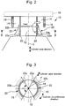
- Fig. 2 is a schematic diagram that shows a cross-sectional shape of the cylinder block 10 taken along the line A-A in Fig. 1 .
- the line A-A passes through the center of each of the cylinder bores 12 in the view of the cylinder block 10 from the cylinder axial direction.
- the cylinder bore wall section 14 according to the present embodiment includes cylindrical cylinder liners 20 for forming the respective cylinder bores 12.
- the inner circumference surface of each of the cylinder liners 20 serves as the circumference surface of each of the cylinder bores 12.
- Each of the cylinder liners 20 is formed so as to correspond to the sliding range of the piston in the cylinder axial direction, and, in other words, is formed so as to substantially cover the whole of the cylinder bore 12.
- the water jacket 16 is formed so as to surround a part of the cylinder bore 12 in the cylinder axial direction (more specifically, a part of the cylinder bore 12 at a location closer to the cylinder head 18).
- the cylinder bore wall section 14 includes hollow portions 22 for the respective cylinder bores 12.
- Each of the hollow portions 22 is formed in the cylinder bore wall section 14 at a location on the side away from the cylinder head 18 in the cylinder axial direction. More specifically, in the example shown in Fig. 2 , with respect to the cylinder axial direction, each of the hollow portions 22 is formed so as to extend from the vicinity of the end part of the water jacket 16 on the side away from the cylinder head 18 to the vicinity of the end part of the cylinder liner 20 on the side away from the cylinder head 18 (in other words, to the vicinity of the end on the side of the bottom dead center in the sliding range of the piston).
- each of the hollow portions 22 is formed so as to be located between the cylinder liner 20 and the water jacket 16, for example.
- each of the hollow portions 22 is provided at a location closer to the circumference surface of the cylinder bore 12.
- an inner circumference surfaces 22a of each hollow portion 22 facing the cylinder liner 20 is formed so as to be parallel to the cylinder axis line L, as an example.
- each of the hollow portions 22 is formed such that the width of the hollow portion 22 in the cylinder radial direction is greater on the side away from the cylinder head 18 in the cylinder axial direction than on the side closer to the cylinder head 18. More specifically, each of the hollow portions 22 is formed such that the width of the hollow portion 22 in the cylinder radial direction becomes gradually (in more detail, continuously) greater as the hollow portion 22 is farther away from the cylinder head 18 in the cylinder axial direction. In other words, each of the hollow portions 22 gradually (in more detail, continuously) enlarges in the cylinder radial direction as the hollow portion 22 is farther away from the cylinder head 18 in the cylinder axial direction. Also, in the example shown in Fig.
- each hollow portion 22 in the cylinder radial direction becomes greatest at the end thereof on the side away from the cylinder head 18 in the cylinder axial direction.
- an outer circumference surface 22b of each hollow portion 22 on the outer side in the cylinder radial direction is shaped with a curve (as an example, a curve that is convex to the inner side in the cylinder radial direction) in the cross-section of the cylinder block 10 that is perpendicular to the cylinder axis line L as shown in Fig. 2 .
- each of the hollow portions 22 according to the present embodiment is formed, for example, as a space having a constant width in the cylinder circumferential direction.
- the area of the cross-sections of each hollow portion 22 that are perpendicular to the cylinder axis direction gradually increases as the hollow portion 22 is farther away from the cylinder head 18 in the cylinder axial direction.
- Fig. 3 is a diagram that shows a cross-sectional shape of the cylinder block 10 taken along the line B-B in Fig. 2 .
- the line B-B is perpendicular to the cylinder axis line L at a location at which the hollow portion 22 is present.
- the location of each hollow portion 22 with respect to the cylinder circumferential direction is further defined as follows with a positional relationship between the hollow portion 22 and the water jacket 16. More specifically, in the view of the cylinder block 10 from the cylinder axial direction as shown in Fig. 3 , each of the hollow portions 22 is formed only at a location of the cylinder bore wall section 14 on the inner side in the cylinder radial direction than the water jacket 16.
- each of the hollow portions 22 is not formed at a location between the cylinder bores 12 at which the water jacket 16 is not provided.
- each of the hollow portions 22 is formed so as to fall within a range of angle ⁇ around the center point P of the cylinder bore 12, that is, a range in which the water jacket 16 is present.
- each of the hollow portions 22 according to the present embodiment is provided in such a manner that the hollow portion 22 is divided into two sub-portions per cylinder bore 12.
- the water jacket 16 is present in such a manner as to exceed the range of angle ⁇ described above and to extend to the opposite ends in the row direction of the cylinder bores 12, in contrast to two cylinder bores 12 located on the center side.
- the hollow portions 22 thereof may be formed additionally in such a manner as to exceed the range of angle ⁇ .
- the formation of the hollow portions 22 in a manner shown in Fig. 3 is also applied to the two cylinder bores 12 located at the opposite ends.
- the cylinder block 10 in which the hollow portions 22 are formed can be produced by a three-dimensional molding machine, for example.
- the cylinder block 10 is formed by a metal material (as an example, aluminum alloy).
- the cylinder block 10 having the hollow portions 22 can be, for example, produced by casting as follows, instead of the three-dimensional molding machine.
- the hollow portions 22 can be formed by, for example, inserting dissipating cores into a mold for forming the cylinder block 10. Additionally, if this alternative method is used, it is required to allow the cylinder block 10 to have channels for removing gases derived as a result of the dissipating cores being gasified when the cylinder block 10 is produced by casting, and the channels are required to be blocked after the casting process.
- the supply of heat from combustion gas to a cylinder bore wall section is performed mainly with respect to a location of the cylinder bore wall section on the side closer to a cylinder head. Also, the longer the distance from the cylinder head is, the greater the influence of the heat from the combustion gas to the cylinder bore wall section becomes. Therefore, if no special consideration is given, the temperature of the cylinder bore wall section is basically higher on the side closer to the cylinder head than on the side away from the cylinder head. In more detail, the longer the distance from the cylinder head is, the lower the temperature of the cylinder bore wall section becomes. As a result of this, a temperature difference in the cylinder axial direction may be produced in the cylinder bore wall section.
- the cylinder bore wall section 14 of the cylinder block 10 includes the hollow portions 22 on the side away from the cylinder head 18 in the cylinder axial direction as described so far.
- Each of the hollow portions 22 serves as a heat insulating layer, and hinders heat transfer in the cylinder bore wall section 14 from the side of the cylinder bore 12 toward the outer side in the cylinder radial direction. Therefore, with the configuration of the cylinder bore wall section 14 according to the present embodiment, as shown by the length of arrows in Fig.
- the heat transfer (heat convection) from the side of each of the cylinder bores 12 toward the cylinder bore wall section 14 is facilitated at the location of the cylinder bore wall section 14 on the side where the hollow portion 22 is not provided (that is, at the location thereof on the side closer to the cylinder head 18).
- the cylinder block 10 according to the present embodiment includes the water jacket 16, and thus, heat transfer toward the water jacket 16 is facilitated.
- the heat transfer toward the cylinder bore wall section 14 is reduced by the hollow portion 22.
- each of the hollow portions 22 is provided in the cylinder bore wall section 14 on the side away from the cylinder head 18 in the cylinder axial direction, and is formed such that the width of the hollow portion 22 in the cylinder radial direction is greater on the side away from the cylinder head 18 in the cylinder axial direction than on the side closer to the cylinder head 18. More specifically, each of the hollow portions 22 is formed such that the width of the hollow portion 22 in the cylinder radial direction is gradually greater as the hollow portion 22 is farther away from the cylinder head 18 in the cylinder axial direction.
- the temperature difference in the cylinder bore wall section 14 (more specifically, the temperature difference at the location closer to the circumference surface of each of the cylinder bores 12) in the cylinder axial direction can be reduced effectively.
- friction accompanying the slide of the pistons can be reduced and piston slap can be reduced.
- each of the hollow portions 22 is provided in the cylinder circumferential direction is determined on the basis of the positional relationship between the hollow portion 22 and the water jacket 16.
- each of the hollow portions 22 is formed only at the location of the cylinder bore wall section 14 on the inner side in the cylinder radial direction than the water jacket 16.
- Fig. 4 is a schematic diagram for describing a configuration of hollow portions 32 included in a cylinder block 30 according to the second embodiment of the present disclosure.
- Fig. 4 shows a cross sectional shape of the cylinder block 30 at the similar position to that in Fig. 2 .
- each of the hollow portions 22 according to the first embodiment is formed such that the width of the hollow portion 22 in the cylinder radial direction becomes greater continuously as the distance from the cylinder head 18 in the cylinder axial direction becomes longer.
- each of the hollow portions 32 according to the present embodiment is formed such that the width of the hollow portion 32 in the cylinder radial direction becomes greater gradually as the distance from the cylinder head 18 in the cylinder axial direction becomes longer. More specifically, as one example of this formation, each of the hollow portions 32 according to the present embodiment is formed in such a manner that, as shown in Fig.
- the width of the hollow portion 32 in the cylinder radial direction becomes greater in a stepwise fashion as the distance from the cylinder head 18 in the cylinder axial direction becomes longer.
- the temperature difference in the cylinder bore wall section 14 (more specifically, the temperature difference at the location closer to the circumference surface of each of the cylinder bores 12) in the cylinder axial direction can be reduced.
- FIG. 5 is a schematic diagram for describing a configuration of hollow portions 42 included in a cylinder block 40 according to the third embodiment of the present disclosure.
- Fig. 5 shows a cross sectional shape of the cylinder block 40 at the similar position to that in Fig. 2 .
- the difference between the cylinder block 40 according to the present embodiment and the cylinder block 10 according to the first embodiment is as follows.
- the outer circumferential surface 22b of each of the hollow portions 22 on the outer side in the cylinder radial direction according to the first embodiment is formed in the curved shape as shown by the cross-section that is perpendicular to the cylinder axis line L in Fig. 2 .
- an outer circumferential surface 42b of each of the hollow portions 42 on the outer side in the cylinder radial direction according to the present embodiment is formed by a line as shown by a cross-section that is perpendicular to the cylinder axial line L in Fig. 5 .
- the temperature difference in the cylinder bore wall section 14 (more specifically, the temperature difference at the location closer to the circumference surface of each of the cylinder bores 12) in the cylinder axial direction can be reduced.
- each of the hollow portions 22, 32 or 42 is formed only at the location of the cylinder bore wall section 14 on the inner side in the cylinder radial direction than the water jacket 16.
- one or more hollow portions according to the present disclosure may be formed over the entire cylinder-circumferential direction, as needed.
- the width of each of the hollow portions 22, 32 or 42 in the cylinder radial direction is greatest at an end on the side away from the cylinder head 18 in the cylinder axial direction.
- the effect of the reduction of the temperature difference in the cylinder bore wall section in the cylinder axial direction can be achieved, as far as it meets the requirement that the hollow portion is formed such that the width of the hollow portion in the cylinder radial direction is greater at the location of the cylinder bore wall section 14 on the side away from the cylinder head in the cylinder axial direction than at the location of the cylinder bore wall section 14 on the side closer to the cylinder head.
- the width of the hollow portion in the cylinder radial direction may not be necessarily greatest at an end on the side away from the cylinder head 18 in the cylinder axial direction, as far as it meets the requirement that the location of the cylinder bore wall section on the side closer to the cylinder head in the cylinder axial direction and the location of the cylinder bore wall section on the side away therefrom have the relationship described above.
- the hollow portion contributes to the reduction of the temperature difference in the cylinder bore wall section in the cylinder axial direction even if the location of the cylinder bore wall section 14 on the side closer to the cylinder head in the cylinder axial direction and the location thereof on the side away therefrom are not formed integrally (that is, as one hollow space). Therefore, the hollow portion according to the present disclosure may be divided into arbitrary number of sub-portions in the cylinder axial direction.
- the cylinder block that is, a cylinder block for a water-cooled internal combustion engine 10 10, 30 or 40 is used.
- one or more hollow portions according to the present disclosure may be applied to a cylinder block that does not include a water jacket (for example, a cylinder block for an air-cooled internal combustion engine).
- the hollow portion according to the present disclosure may be applied to a cylinder block that does not include a cylinder liner instead of the examples described above.
Landscapes
- Engineering & Computer Science (AREA)
- Chemical & Material Sciences (AREA)
- Combustion & Propulsion (AREA)
- Mechanical Engineering (AREA)
- General Engineering & Computer Science (AREA)
- Cylinder Crankcases Of Internal Combustion Engines (AREA)
Applications Claiming Priority (1)
| Application Number | Priority Date | Filing Date | Title |
|---|---|---|---|
| JP2016167110A JP2018035692A (ja) | 2016-08-29 | 2016-08-29 | 内燃機関のシリンダブロック |
Publications (1)
| Publication Number | Publication Date |
|---|---|
| EP3290676A1 true EP3290676A1 (de) | 2018-03-07 |
Family
ID=59858499
Family Applications (1)
| Application Number | Title | Priority Date | Filing Date |
|---|---|---|---|
| EP17188418.2A Withdrawn EP3290676A1 (de) | 2016-08-29 | 2017-08-29 | Zylinderblock für einen verbrennungsmotor |
Country Status (4)
| Country | Link |
|---|---|
| US (1) | US20180058369A1 (de) |
| EP (1) | EP3290676A1 (de) |
| JP (1) | JP2018035692A (de) |
| CN (1) | CN107781055A (de) |
Citations (7)
| Publication number | Priority date | Publication date | Assignee | Title |
|---|---|---|---|---|
| DE4324609A1 (de) * | 1993-07-22 | 1995-01-26 | Avl Verbrennungskraft Messtech | Kurbelgehäuse für Brennkraftmaschinen |
| EP1205658A1 (de) * | 2000-11-07 | 2002-05-15 | Ford Global Technologies, Inc., A subsidiary of Ford Motor Company | Zylinderblock für eine Verbrennungskraftmaschine |
| JP2007154739A (ja) * | 2005-12-05 | 2007-06-21 | Nissan Motor Co Ltd | シリンダブロック |
| JP2010169049A (ja) | 2009-01-26 | 2010-08-05 | Toyota Motor Corp | 内燃機関および内燃機関の制御装置 |
| JP2010190138A (ja) | 2009-02-19 | 2010-09-02 | Toyoda Gosei Co Ltd | ウォータジャケット構造 |
| JP2011174450A (ja) * | 2010-02-25 | 2011-09-08 | Daihatsu Motor Co Ltd | シリンダブロック |
| JP2015229988A (ja) | 2014-06-06 | 2015-12-21 | Nok株式会社 | ウォータージャケットスペーサ |
Family Cites Families (10)
| Publication number | Priority date | Publication date | Assignee | Title |
|---|---|---|---|---|
| US4244330A (en) * | 1978-11-13 | 1981-01-13 | Cummins Engine Company, Inc. | Engine cylinder liner having a mid stop |
| JP3048401B2 (ja) * | 1991-05-16 | 2000-06-05 | マツダ株式会社 | エンジンのシリンダブロック構造 |
| US5253615A (en) * | 1992-12-24 | 1993-10-19 | Ford Motor Company | Cylinder block cylinder bore isolator |
| CN2412096Y (zh) * | 2000-03-16 | 2000-12-27 | 中国船舶重工集团公司第七研究院第七一一研究所 | 水冷柴油机干式缸套机体 |
| JP4496844B2 (ja) * | 2004-05-19 | 2010-07-07 | いすゞ自動車株式会社 | 遮熱エンジン |
| JP4595919B2 (ja) * | 2006-10-19 | 2010-12-08 | トヨタ自動車株式会社 | ウォータジャケット中子、シリンダブロック及びその製造方法 |
| JP4224725B1 (ja) * | 2007-11-08 | 2009-02-18 | トヨタ自動車株式会社 | シリンダブロックおよびその製造方法 |
| US8191529B2 (en) * | 2008-07-03 | 2012-06-05 | Caterpillar Inc. | Method of manufacturing an engine block |
| CN201486637U (zh) * | 2009-07-31 | 2010-05-26 | 奇瑞汽车股份有限公司 | 一种新型的柴油机冷却结构 |
| JP2014231791A (ja) * | 2013-05-29 | 2014-12-11 | アイシン精機株式会社 | 内燃機関 |
-
2016
- 2016-08-29 JP JP2016167110A patent/JP2018035692A/ja active Pending
-
2017
- 2017-07-04 CN CN201710536182.8A patent/CN107781055A/zh active Pending
- 2017-07-06 US US15/642,551 patent/US20180058369A1/en not_active Abandoned
- 2017-08-29 EP EP17188418.2A patent/EP3290676A1/de not_active Withdrawn
Patent Citations (7)
| Publication number | Priority date | Publication date | Assignee | Title |
|---|---|---|---|---|
| DE4324609A1 (de) * | 1993-07-22 | 1995-01-26 | Avl Verbrennungskraft Messtech | Kurbelgehäuse für Brennkraftmaschinen |
| EP1205658A1 (de) * | 2000-11-07 | 2002-05-15 | Ford Global Technologies, Inc., A subsidiary of Ford Motor Company | Zylinderblock für eine Verbrennungskraftmaschine |
| JP2007154739A (ja) * | 2005-12-05 | 2007-06-21 | Nissan Motor Co Ltd | シリンダブロック |
| JP2010169049A (ja) | 2009-01-26 | 2010-08-05 | Toyota Motor Corp | 内燃機関および内燃機関の制御装置 |
| JP2010190138A (ja) | 2009-02-19 | 2010-09-02 | Toyoda Gosei Co Ltd | ウォータジャケット構造 |
| JP2011174450A (ja) * | 2010-02-25 | 2011-09-08 | Daihatsu Motor Co Ltd | シリンダブロック |
| JP2015229988A (ja) | 2014-06-06 | 2015-12-21 | Nok株式会社 | ウォータージャケットスペーサ |
Also Published As
| Publication number | Publication date |
|---|---|
| CN107781055A (zh) | 2018-03-09 |
| US20180058369A1 (en) | 2018-03-01 |
| JP2018035692A (ja) | 2018-03-08 |
Similar Documents
| Publication | Publication Date | Title |
|---|---|---|
| JP6090535B2 (ja) | 内燃機関 | |
| JP4224725B1 (ja) | シリンダブロックおよびその製造方法 | |
| US8256389B2 (en) | Cylinder block | |
| JP2007127066A (ja) | 内燃機関の冷却構造及び水路形成部材 | |
| CN104718369A (zh) | 具有埋头孔设计的钢活塞 | |
| US10823109B2 (en) | Piston for an internal combustion engine | |
| US10174712B2 (en) | Piston for an internal combustion engine | |
| US7975601B2 (en) | Engine cylinder liner | |
| EP3290676A1 (de) | Zylinderblock für einen verbrennungsmotor | |
| US20150260079A1 (en) | Cylinder block | |
| JP2017141780A (ja) | 内燃機関のシリンダブロック | |
| JP6117575B2 (ja) | 鋳造用金型装置 | |
| JP2018025110A (ja) | 内燃機関 | |
| US20190063365A1 (en) | Piston with broad ovate gallery | |
| JP6821247B2 (ja) | オープンデッキ型シリンダブロック | |
| JP7280073B2 (ja) | 多気筒内燃機関用シリンダブロック及びその製造方法 | |
| US20200284218A1 (en) | Cylinder block | |
| EP2963274A1 (de) | Verbrennungsmotor | |
| JP2012112332A (ja) | 内燃機関のシリンダブロック | |
| JP7134568B2 (ja) | 内燃機関のシリンダの構造 | |
| US20040182352A1 (en) | Engine of reciprocating piston type | |
| JPH10252551A (ja) | エンジンのシリンダブロック構造 | |
| JP2008190472A (ja) | シリンダブロックおよびシリンダライナ | |
| JPWO2016088454A1 (ja) | 内燃機関用ピストンと該ピストンの製造方法及び製造装置 | |
| KR20170109888A (ko) | 실린더 라이너 및 이를 포함하는 실린더 블록 |
Legal Events
| Date | Code | Title | Description |
|---|---|---|---|
| PUAI | Public reference made under article 153(3) epc to a published international application that has entered the european phase |
Free format text: ORIGINAL CODE: 0009012 |
|
| STAA | Information on the status of an ep patent application or granted ep patent |
Free format text: STATUS: REQUEST FOR EXAMINATION WAS MADE |
|
| 17P | Request for examination filed |
Effective date: 20170929 |
|
| AK | Designated contracting states |
Kind code of ref document: A1 Designated state(s): AL AT BE BG CH CY CZ DE DK EE ES FI FR GB GR HR HU IE IS IT LI LT LU LV MC MK MT NL NO PL PT RO RS SE SI SK SM TR |
|
| AX | Request for extension of the european patent |
Extension state: BA ME |
|
| STAA | Information on the status of an ep patent application or granted ep patent |
Free format text: STATUS: THE APPLICATION HAS BEEN WITHDRAWN |
|
| 18W | Application withdrawn |
Effective date: 20190130 |