EP3288045B1 - Elektromagnetische spulen und verfahren zur herstellung davon - Google Patents
Elektromagnetische spulen und verfahren zur herstellung davon Download PDFInfo
- Publication number
- EP3288045B1 EP3288045B1 EP17185433.4A EP17185433A EP3288045B1 EP 3288045 B1 EP3288045 B1 EP 3288045B1 EP 17185433 A EP17185433 A EP 17185433A EP 3288045 B1 EP3288045 B1 EP 3288045B1
- Authority
- EP
- European Patent Office
- Prior art keywords
- resin
- wire
- conductor
- coiled conductor
- electromagnetic coil
- Prior art date
- Legal status (The legal status is an assumption and is not a legal conclusion. Google has not performed a legal analysis and makes no representation as to the accuracy of the status listed.)
- Not-in-force
Links
Images


Classifications
-
- H—ELECTRICITY
- H01—ELECTRIC ELEMENTS
- H01F—MAGNETS; INDUCTANCES; TRANSFORMERS; SELECTION OF MATERIALS FOR THEIR MAGNETIC PROPERTIES
- H01F27/00—Details of transformers or inductances, in general
- H01F27/28—Coils; Windings; Conductive connections
- H01F27/32—Insulating of coils, windings, or parts thereof
-
- H—ELECTRICITY
- H01—ELECTRIC ELEMENTS
- H01B—CABLES; CONDUCTORS; INSULATORS; SELECTION OF MATERIALS FOR THEIR CONDUCTIVE, INSULATING OR DIELECTRIC PROPERTIES
- H01B3/00—Insulators or insulating bodies characterised by the insulating materials; Selection of materials for their insulating or dielectric properties
- H01B3/002—Inhomogeneous material in general
- H01B3/006—Other inhomogeneous material
-
- H—ELECTRICITY
- H01—ELECTRIC ELEMENTS
- H01B—CABLES; CONDUCTORS; INSULATORS; SELECTION OF MATERIALS FOR THEIR CONDUCTIVE, INSULATING OR DIELECTRIC PROPERTIES
- H01B3/00—Insulators or insulating bodies characterised by the insulating materials; Selection of materials for their insulating or dielectric properties
- H01B3/02—Insulators or insulating bodies characterised by the insulating materials; Selection of materials for their insulating or dielectric properties mainly consisting of inorganic substances
- H01B3/08—Insulators or insulating bodies characterised by the insulating materials; Selection of materials for their insulating or dielectric properties mainly consisting of inorganic substances quartz; glass; glass wool; slag wool; vitreous enamels
- H01B3/082—Wires with glass or glass wool
-
- H—ELECTRICITY
- H01—ELECTRIC ELEMENTS
- H01B—CABLES; CONDUCTORS; INSULATORS; SELECTION OF MATERIALS FOR THEIR CONDUCTIVE, INSULATING OR DIELECTRIC PROPERTIES
- H01B7/00—Insulated conductors or cables characterised by their form
- H01B7/17—Protection against damage caused by external factors, e.g. sheaths or armouring
- H01B7/29—Protection against damage caused by extremes of temperature or by flame
- H01B7/292—Protection against damage caused by extremes of temperature or by flame using material resistant to heat
-
- H—ELECTRICITY
- H01—ELECTRIC ELEMENTS
- H01F—MAGNETS; INDUCTANCES; TRANSFORMERS; SELECTION OF MATERIALS FOR THEIR MAGNETIC PROPERTIES
- H01F27/00—Details of transformers or inductances, in general
- H01F27/28—Coils; Windings; Conductive connections
- H01F27/2823—Wires
-
- H—ELECTRICITY
- H01—ELECTRIC ELEMENTS
- H01F—MAGNETS; INDUCTANCES; TRANSFORMERS; SELECTION OF MATERIALS FOR THEIR MAGNETIC PROPERTIES
- H01F27/00—Details of transformers or inductances, in general
- H01F27/28—Coils; Windings; Conductive connections
- H01F27/32—Insulating of coils, windings, or parts thereof
- H01F27/324—Insulation between coil and core, between different winding sections, around the coil; Other insulation structures
- H01F27/325—Coil bobbins
-
- H—ELECTRICITY
- H01—ELECTRIC ELEMENTS
- H01F—MAGNETS; INDUCTANCES; TRANSFORMERS; SELECTION OF MATERIALS FOR THEIR MAGNETIC PROPERTIES
- H01F41/00—Apparatus or processes specially adapted for manufacturing or assembling magnets, inductances or transformers; Apparatus or processes specially adapted for manufacturing materials characterised by their magnetic properties
- H01F41/02—Apparatus or processes specially adapted for manufacturing or assembling magnets, inductances or transformers; Apparatus or processes specially adapted for manufacturing materials characterised by their magnetic properties for manufacturing cores, coils, or magnets
- H01F41/04—Apparatus or processes specially adapted for manufacturing or assembling magnets, inductances or transformers; Apparatus or processes specially adapted for manufacturing materials characterised by their magnetic properties for manufacturing cores, coils, or magnets for manufacturing coils
- H01F41/06—Coil winding
- H01F41/064—Winding non-flat conductive wires, e.g. rods, cables or cords
- H01F41/066—Winding non-flat conductive wires, e.g. rods, cables or cords with insulation
-
- H—ELECTRICITY
- H01—ELECTRIC ELEMENTS
- H01F—MAGNETS; INDUCTANCES; TRANSFORMERS; SELECTION OF MATERIALS FOR THEIR MAGNETIC PROPERTIES
- H01F41/00—Apparatus or processes specially adapted for manufacturing or assembling magnets, inductances or transformers; Apparatus or processes specially adapted for manufacturing materials characterised by their magnetic properties
- H01F41/02—Apparatus or processes specially adapted for manufacturing or assembling magnets, inductances or transformers; Apparatus or processes specially adapted for manufacturing materials characterised by their magnetic properties for manufacturing cores, coils, or magnets
- H01F41/04—Apparatus or processes specially adapted for manufacturing or assembling magnets, inductances or transformers; Apparatus or processes specially adapted for manufacturing materials characterised by their magnetic properties for manufacturing cores, coils, or magnets for manufacturing coils
- H01F41/12—Insulating of windings
- H01F41/127—Encapsulating or impregnating
-
- H—ELECTRICITY
- H01—ELECTRIC ELEMENTS
- H01F—MAGNETS; INDUCTANCES; TRANSFORMERS; SELECTION OF MATERIALS FOR THEIR MAGNETIC PROPERTIES
- H01F5/00—Coils
- H01F5/06—Insulation of windings
Definitions
- the present patent document relates generally to devices having electrical windings and methods for making the same. More specifically, the present patent document relates to electromagnetic coils that can withstand harsh environments, can be cost effectively manufactured and can efficiently operate.
- Electrical windings are the building blocks of many devices including actuators, electromagnets, inductors, transformers and transducers to name a few. Many of these devices are used in aerospace applications and other applications where they may face harsh environments such as extreme temperatures and high vibration. In order to be effective, these devices need to operate efficiently and need to meet a weight tolerance.
- Fig. 1 is a trace from a fireproof test which shows what typically happens when you expose conventional coils to excessive heat.
- the test was performed at a constant electrical current through the solenoid coil.
- the voltage is plotted along the Y-axis as a function of time along the X-axis.
- the fire test heats the unit the voltage increases, because the coil resistance increases with temperature.
- the organic insulation on the coil wires starts to char, leaving carbon rich compounds which are conductive, leading to a drop in voltage as the overall coil resistance drops. This typically occurs in several distinct phases due to the specific chemistry at any given point. Functional failure occurred after approximately 450s when there were insufficient functional turns in the coil to maintain the magnetic field.
- an electromagnetic coil comprises: a bobbin made entirely of ceramic; a coiled conductor wrapped around the bobbin; a potting resin applied to the coiled conductor during winding wherein, the resin is a siloxane polymer mixed with a metal oxide ; and an overwind made of glass fiber yarn.
- the coiled conductor is formed from a wire that has a coating of non-conductive inorganic compounds i.e. aluminum oxide and silicon dioxide.
- the coiled conductor is formed from a wire that is glass coated and drawn to the correct diameter.
- the wire is a Commercial Off the Shelf (COTS) conductive wire.
- COTS Commercial Off the Shelf
- the metal oxide is Titanium dioxide.
- the titanium dioxide comprises greater than 50% by mass of the potting resin.
- the filler used in the potting resin comprises between 55% and 62% by mass of the potting resin.
- the filler is a metal oxide.
- the siloxane resin in maintained in the non-ceramic phase by curing it to no more than 250°C.
- the leads are formed from coil wire and use a glass or mineral fiber sleeve to insulate the leads.
- a method of making an electromagnetic coil comprises: winding a conductor around a non-removable bobbin made entirely of ceramic to form a coiled conductor; applying a siloxane polymer resin mixed with a metal oxide to the conductor during the winding step; and winding an overwind of glass fiber yarn over the coiled conductor.
- the present patent document discloses embodiments and examples of a coiled conductor that are designed to withstand harsh environments while still performing efficiently.
- the embodiments and examples may be divided into two separate categories.
- Fig. 2 illustrates a coiled conductor 10.
- the conductor 12 is a wire but it may be any type of conductor.
- the conductor 12 may be made from any type conductive material including solid nickel, nickel clad copper, copper, aluminum, silver, gold, steel, tin, or any other conductive material.
- the conductor 12 may be coated or a plurality of materials may be combined to create a conductor 12.
- a polymer coating, an amorphous ceramic coating or a polycrystalline ceramic coating may be used.
- silver plating, nickel plating, tin plating or some other type of plating may be used.
- the conductive wire may be made from a plurality of smaller diameter strands of wire to form conductor 12.
- ceramic coated nickel clad copper wire or ceramic coated solid nickel wire may be used.
- coil conductor means any conductor 12 in the shape of a coil, spiral or helix.
- the term “coiled conductor” itself does not require that the conductor 12 is wound around a core, although it may be. As may be seen in Fig. 2 , the conductor 12 is wound into a coil.
- the conductor 12 is tightly wound or wound with multiple layers, the individual winds of the conductor 12 will come in contact. In such examples, the conductor 12 will need to have an insulating coating to prevent the individual winds of the coil from contacting each other.
- the conductor 12 is a COTS wire.
- the wire may have a ceramic coating that has been deposited by chemical or plasma vapor deposition. In some examples, the coating is Aluminum Oxide and Silicon Dioxide. In other examples, the wire may be glass coated and drawn to the correct diameter.
- a large advantage of using COTS wire is the reduction of manufacturing time and costs. Unlike many of the existing designs that create electromagnetic coils that can withstand harsh environments, examples of the current design are not required to have a conductor that is specially coated or created in a preprocessing step. In addition, using COTS wire avoids additional ITAR issues.
- Fig. 3 illustrates an isometric view of one example of an electromagnetic coil 14.
- the electromagnetic coil 14 may also be referred to as a solenoid.
- the electromagnetic coil 14 includes a conductor 12 wound in a coil around a core 16.
- the core 16 may also be referred to as a former or bobbin.
- the coiled conductor 10 is formed by wrapping the wire around the core 16.
- the core 16 is just a removable support structure for forming the coiled conductor 10.
- the coiled conductor 10 is formed around the core 16 and the core 16 remains an integral part of the final electromagnetic coil 14.
- the core 16 may be made from metal, ceramic or other types of materials. In particular, stainless steel, anodized aluminum, or Alumina may be used. The core 16 may also have insulating coatings applied. However, according to the invention, the core 16 is made entirely out of a ceramic like Alumina. Manufacturing the core 16 out of a ceramic material provides a dielectric barrier to the leakage of electrical current from the coil. This increases efficiency of the coil and maintains an attractive weight budget. Ceramic cores are also highly heat resistant and allow the final product to withstand higher temperatures.
- the conductor 12 is wound in a tightly packed helix.
- the electromagnetic coil 14 produces a magnetic field when an electrical current is passed through the conductor.
- Typical electromagnetic coils have a metallic core 16. While examples not being part of the present invention may have a core made from a metal or metal alloy, the invention use a ceramic core. In the invention, the core 16 is made entirely of ceramic. The ceramic core is light weight and can withstand extremely high temperatures. In preferred embodiments, wire is wrapped around a non-removable ceramic bobbin 16 to form the coiled conductor 10.
- Fig. 4 illustrates a cross section of one example of an electromagnetic coil assembly 20.
- the example shown in Fig. 4 includes a housing 24 that encases the coiled conductor 10 and the core 16.
- a sealant may be used to ensure the winding is resistant to environmental conditions.
- Typical coils may use polyurethane varnish or epoxy resin.
- the sealant is made from a high temperature material. In preferred examples, designed to withstand temperature ranges up to 400°C, heat or ultraviolet labile Silsesquioxane compounds may be used.
- Preferred examples may include, but are not limited to, poly(2-Acetoxyethylsilsesquioxane), poly(2-Chloroethylsilsesquioxane or poly(2-Bromoethylsilsesquioxane).
- a resin is added during manufacture to secure the coil windings in place.
- the resin is applied while the wire is being wrapped on the core 16.
- more resin may be applied to an overwind 28 to secure the overwind 28 in place as well. See Fig. 7 .
- the resin may be brushed or sprayed on as the conductor 12 is wrapped around the bobbin 16. The resin provides strength and resistance to the environment while preventing the Lorentz force from fatiguing the wires.
- the resin is based on a siloxane.
- the resin may be a medium viscosity siloxane polymer, such that the resin may be applied directly or when thinned using solvents.
- the siloxane polymer is a phenylmethyl polysiloxane resin.
- Such a polymer is a siloxane with methyl and phenyl pendant groups.
- Fig. 6 illustrates VinylPhenylMethyl Terminated VinylPhenylsiloxane - PhenylMethylsiloxane Copolymer.
- the siloxane polymer may be: Vinyl Terminated Poly Dimethyl-Diphenyl siloxane copolymer; Vinyl Terminated Poly Phenylmethyl siloxane copolymer; VinylPhenylMethyl Terminated Poly VinylPhenylsiloxane - PhenylMethylsiloxane Copolymer; Hydride Terminated Poly Dimethyl-Diphenyl siloxane copolymer; or Hydride Terminated Poly Phenylmethyl siloxane copolymer.
- a siloxane polymer with vinyl groups and high phenyl content are used. Tego's Silikophn P 80/X i may be used.
- Silres REN80 i may be used. Siloxane resins are readily available from manufacturers such as Tego® (www.tego.us); Wacker® (www.wacker.com), Momentive® (www.momentive.com), Bluesil® and many others.
- the siloxane is mixed with an inorganic compound to form a siloxane compound.
- the norganic compound is a metal oxide.
- the metal oxide is Titanium Dioxide (TiO 2 ).
- the Titanium Dioxide may be the Rutile polymorph.
- the ideal ratio of inorganic compound to base resin is between 50% and 70% filler by mass of those two components. Any greater than 70% will typically require thinning with solvents to ensure usability during manufacture.
- the inorganic filler is required because straight siloxane has a tendency to form bubbles and foam during curing. This is due to the release of volatile compounds into the part-cured resin.
- the inorganic filler serves to reduce the percentage of volatiles produced by mass and to provide channels for the volatile compounds to escape. Too little and the bubbling remains, too much and the material becomes a stiff paste.
- the amount of filler is between 55% and 62%.
- the siloxanes may have functional Vinyl groups where curing and crosslinking occurs.
- the siloxane polymer may have other additives including reagents to cause curing and cross-linking at elevated temperatures. These additives are specific to the regime used and are either Platinum or Rhodium catalysts cured between Vinyl and Hydride groups or Peroxide cured between Vinyl and Methyl groups. Platinum and Rhodium catalysts are typically added up to 250 ppm and Peroxides up to 10,000 ppm. Further cross-linking may be achieved with specific cross-linking agents. Yet further modification of the reaction process may include inhibitors and moderators.
- Platinum catalysts used include but are not limited to: Platinum Carbonyl Cyclovinylmethylsiloxane Complex, Platinum - Divinyltetramethyldisiloxane Complex , Platinum - Divinyltetramethyldisiloxane Complex, Platinum - Divinyltetramethyldisiloxane Complex, Platinum - Cyclovinylmethylsiloxane Complex, Platinum-Octanaldehyde/Octanol Complex and Tris(Dibutylsulfide)Rhodium Trichloride.
- Peroxide curing agents include but are not limited to Dichlorobenzoyl Peroxide and Dicumyl Peroxide.
- Crosslinking agents may include but are not limited to: Phenyltris(Dimethylsiloxy)Silane, Tetrakis(Dimethylsiloxy)Silane and Trifluoropropyltris(Dimethylsiloxy) Silane.
- Moderators and Inhibitors include but are not limited to: Divinyltetramethyldiloxane and Tetravinyltetramethlycyclotetrasoloxane.
- the base resin may be mixed with lamellar fillers such as Mica or Montmorillonite, or acicular fillers such as Wollastonite or Halloysite. These fillers may be added in ratios up to 35% by mass to the inorganic compound/base resin mixture.
- the base resin may also be mixed with thermally stabilizing pigments such as spinelle pigments, FeMn pigments, Mangesium Aluminate or Manganese Iron Oxide. These stabilizers may be added in ratios up to 70% of the total mixture by mass.
- the base resin may also be further modified with solvents, de-foaming or de-aerating compounds. De-foaming and de-aerating compounds include but are not limited to (poly)Dimethyl Siloxanes, organically modified (poly) Dimethyl Siloxane and Fluorosilicones.
- the coils may be designed and manufactured to withstand temperatures up to 400°C.
- Siloxane based resins may be generally classified as inorganic resins.
- coils may be made using a resin made from an organic compound with only slightly reduced performance.
- a cyanate ester may be used for the resin.
- Such examples nay not be as temperature resistant as the coils based on siloxane resin but may still be designed to withstand temperatures up to 300°C.
- Novalec Cyanate Ester may be used. In these examples, the Novalec Cyanate Ester becomes a phenolic triazine post-cure.
- Lonza Primaset PT-30 or REX-371 or similar Cyanate Esters may be used.
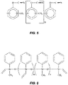
- Lonza Primaset has the chemical structure shown in Fig. 5 .
- the Cyanate Esters described in Fig. 5 may have any number of repeating units N.
- cyanate esters may be used including but not limited to: Bisphenol M Cyanate Ester; Dicyclopentadienylbisphenol Cyanate Ester; Bisphenol A Cyanate Ester; Bisphenol B Cyanate Ester; Bisphenol E Cyanate Ester; Bisphenol P Cyanate Ester; Tetramethylbisphenol F Cyanate Ester; Hexafluorobisphenol A Cyanate Ester; and Phenol Novolac Cyanate Ester.
- the cyanate ester may be used in combination with additives. In other examples, no additives are used.
- resin types may be used including Poly(p-vinyl phenol), Polymides, Bismaleimides, and Phthalonitrile based polymers.
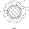
- Fig. 7 illustrates a cross-sectional view of the example of Fig. 4 further comprising an overwind 28.
- the electromagnetic conductor 20 further includes an overwind 28.
- the overwind 28 provides environmental protection for the coiled conductor 10.
- the overwind 28 is made from a glass fiber yarn that is wound around the coiled conductor 10. As discussed above, resin may be applied to the overwind 28 to further secure the overwind 28 and improve its protective qualities.
- embodiments of the present patent document may be cured at much lower temperatures than conventional high temperature coils. Cure temperatures for the embodiments described herein may be approximately 250°C for not less than 30 minutes. Accordingly, embodiments herein do not require a siloxane resin cured to a fully ceramic phase whereby all organic pendant groups are eliminated from the cured matrix.
- the coiled conductor 10 has leads 32 and 34.
- Leads 32 and 34 are simply the ends of the coiled conductor 10 that are used to electrically connect the coiled conductor 10 into a larger electrical system.
- leads 32 and 34 may be located outside the housing 24 of the coiled conductor 10.
- the leads 32 and 34 are created by using terminal posts on the coil.
- the leads 32 and/or 34 may be formed from coil wire using a glass or mineral fiber sleeve to insulate the leads 32 and/or 34.
- the coil leads may be formed during the assembly process whereby a single strand of the coil wire, or a loop flattened to contrive a multitude of strands, is surrounded by an insulating sleeve of glass or ceramic fiber which is fed through an aperture in the cheeks of the bobbin or radially secured to the bobbin prior and subsequent to winding to make the leads.
- the coil wires are terminated via a terminal post or splice to COTS lead wires.
Landscapes
- Engineering & Computer Science (AREA)
- Power Engineering (AREA)
- Manufacturing & Machinery (AREA)
- Chemical & Material Sciences (AREA)
- Inorganic Chemistry (AREA)
- Coils Or Transformers For Communication (AREA)
- Organic Insulating Materials (AREA)
Claims (15)
- Elektromagnetische Spule (14), umfassend:einen Spulenkörper (16), der vollständig aus Keramik gefertigt ist;einen gewickelten Leiter (10), der um den Spulenkörper (16) gewickelt ist;ein Vergussharz, das während des Wickelns auf den gewickelten Leiter (10) aufgebracht wird, wobei das Harz ein Siloxanpolymer ist, das mit einem Metalloxid gemischt ist; und eine Überwicklung (28), die aus Glasfasergarn gefertigt ist.
- Elektromagnetische Spule (14) nach Anspruch 1, wobei der gewickelte Leiter (10) aus einem Draht gebildet ist, der eine Beschichtung aus nichtleitenden anorganischen Verbindungen aufweist.
- Elektromagnetische Spule (14) nach Anspruch 1, wobei der gewickelte Leiter (10) aus einem Draht gebildet ist, der glasbeschichtet ist.
- Elektromagnetische Spule (14) nach Anspruch 1, wobei das Metalloxid Titandioxid ist und das Titandioxid mehr als 50 Massen-% des Vergussharzes umfasst.
- Elektromagnetische Spule (14) nach Anspruch 1, wobei das Siloxanharz in der nichtkeramischen Phase gehalten wird.
- Elektromagnetische Spule (14) nach Anspruch 1, ferner umfassend Leitungen (32, 34), die aus Spulendraht gebildet sind und eine Glashülse verwenden, um die Leitungen zu isolieren.
- Elektromagnetische Spule (14) nach Anspruch 1, wobei Metalloxid zwischen 55 Massen-% und 62 Massen-% des Vergussharzes umfasst.
- Verfahren zur Herstellung einer elektromagnetischen Spule (14), umfassend:Wickeln eines Leiters (12) um einen nicht entfernbaren Spulenkörper (16), der vollständig aus Keramik gefertigt ist, um einen gewickelten Leiter (10) zu bilden;Aufbringen eines mit einem Metalloxid gemischten Siloxanpolymerharzes auf den Leiter (12) während des Wickelschritts; undWickeln einer Überwicklung (28) aus Glasfasergarn über den gewickelten Leiter (10).
- Verfahren nach Anspruch 8, wobei der gewickelte Leiter (10) ein Draht ist, der einem Draht gebildet ist, der eine chemisch oder durch Dampf abgeschiedene Beschichtung aus nichtleitenden anorganischen Verbindungen aufweist.
- Verfahren nach Anspruch 8, wobei der gewickelte Leiter (10) aus einem Draht gebildet ist, der glasbeschichtet ist.
- Verfahren nach Anspruch 8, wobei das Metalloxid Titandioxid ist und das Titandioxid mehr als 50 Massen-% des Vergussharzes umfasst.
- Verfahren nach Anspruch 8, wobei das Verfahren ferner das Härten des Harzes auf ungefähr 250 ºC für nicht weniger als 30 Minuten umfasst.
- Verfahren nach Anspruch 8, ferner umfassend das Bilden von Leitungen (32, 34) aus Spulendraht unter Verwendung einer Glashülse, um die Leitungen zu isolieren.
- Verfahren nach Anspruch 8, ferner umfassend das Bilden von Leitungen (32, 34) aus Spulendraht unter Verwendung einer Mineralfaserhülse, um die Leitungen zu isolieren.
- Verfahren nach Anspruch 8, wobei das Oxid zwischen 55 Massen-% und 62 Massen-% des Vergussharzes umfasst.
Applications Claiming Priority (1)
| Application Number | Priority Date | Filing Date | Title |
|---|---|---|---|
| US15/242,480 US11335497B2 (en) | 2016-08-19 | 2016-08-19 | Electromagnetic coils and methods of making same |
Publications (3)
| Publication Number | Publication Date |
|---|---|
| EP3288045A1 EP3288045A1 (de) | 2018-02-28 |
| EP3288045B1 true EP3288045B1 (de) | 2020-11-18 |
| EP3288045B8 EP3288045B8 (de) | 2021-01-20 |
Family
ID=59699477
Family Applications (1)
| Application Number | Title | Priority Date | Filing Date |
|---|---|---|---|
| EP17185433.4A Not-in-force EP3288045B8 (de) | 2016-08-19 | 2017-08-09 | Elektromagnetische spulen und verfahren zur herstellung davon |
Country Status (2)
| Country | Link |
|---|---|
| US (1) | US11335497B2 (de) |
| EP (1) | EP3288045B8 (de) |
Families Citing this family (4)
| Publication number | Priority date | Publication date | Assignee | Title |
|---|---|---|---|---|
| US11101066B2 (en) * | 2017-08-31 | 2021-08-24 | Sensata Technologies, Inc. | Electromagnetic coil |
| RU2721375C1 (ru) * | 2019-08-05 | 2020-05-19 | Общество с ограниченной ответственностью "Уральский завод новых технологий" | Реактор высокочастотного заградителя |
| DE202020101776U1 (de) * | 2020-04-01 | 2021-07-05 | C. & E. Fein Gmbh | Magnetfuß |
| US12614665B2 (en) | 2023-01-25 | 2026-04-28 | Honeywell International Inc. | Method of fabricating a high-temperature bobbin for electrical device |
Family Cites Families (16)
| Publication number | Priority date | Publication date | Assignee | Title |
|---|---|---|---|---|
| US2899403A (en) | 1959-08-11 | Low viscosity polysiloxanes and com- | ||
| US2941905A (en) | 1957-04-05 | 1960-06-21 | Westinghouse Electric Corp | Filled organopolysiloxane coating for electrical members |
| US3018321A (en) * | 1958-08-28 | 1962-01-23 | Rea Magnet Wire Company Inc | Article of manufacture comprising an insulated electrical conductor and method of making |
| US3024340A (en) * | 1960-01-15 | 1962-03-06 | Bigeault Emile | System for electrically heating premises |
| US3487123A (en) * | 1966-12-07 | 1969-12-30 | Wacker Chemie Gmbh | Casting and impregnating resins containing organosiloxanes |
| JPS5789211A (en) * | 1980-11-25 | 1982-06-03 | Fujikura Ltd | Manufacture of heat resisting insulating coil device |
| DE19808117A1 (de) * | 1998-02-26 | 1999-09-09 | Wacker Chemie Gmbh | RTV-2 Siliconschäume mit niedrigem Druckverformungsrest |
| US6407339B1 (en) | 1998-09-04 | 2002-06-18 | Composite Technology Development, Inc. | Ceramic electrical insulation for electrical coils, transformers, and magnets |
| JP4782906B2 (ja) | 1998-11-24 | 2011-09-28 | 住友電工ウインテック株式会社 | 絶縁電線 |
| JP4039779B2 (ja) * | 1999-01-28 | 2008-01-30 | 太陽誘電株式会社 | チップ状電子部品の製造方法 |
| JP4955851B2 (ja) | 2000-07-19 | 2012-06-20 | 古河電気工業株式会社 | 絶縁樹脂組成物および絶縁電線 |
| ES2318260T3 (es) | 2004-09-09 | 2009-05-01 | Abb Research Ltd. | Bobinas de transformador encapsuladas de tipo seco. |
| DE102006001817A1 (de) | 2006-01-13 | 2007-07-26 | Forschungszentrum Karlsruhe Gmbh | Elektromagnet aus temperaturbeständigem Material |
| JP5924836B2 (ja) | 2011-10-24 | 2016-05-25 | 国立研究開発法人理化学研究所 | 高温超伝導被覆線及びそれを有する高温超伝導コイル |
| US9175137B2 (en) | 2012-11-26 | 2015-11-03 | The United States Of America As Represented By The Secretary Of The Air Force | Method for producing cyanurate networks via inductive heating of silica-coated magnetic nanoparticles |
| US9688880B2 (en) * | 2015-04-09 | 2017-06-27 | Ppg Industries Ohio, Inc. | In situ assembled crystalline colloidal arrays |
-
2016
- 2016-08-19 US US15/242,480 patent/US11335497B2/en active Active
-
2017
- 2017-08-09 EP EP17185433.4A patent/EP3288045B8/de not_active Not-in-force
Non-Patent Citations (1)
| Title |
|---|
| None * |
Also Published As
| Publication number | Publication date |
|---|---|
| EP3288045B8 (de) | 2021-01-20 |
| EP3288045A1 (de) | 2018-02-28 |
| US20180053595A1 (en) | 2018-02-22 |
| US11335497B2 (en) | 2022-05-17 |
Similar Documents
| Publication | Publication Date | Title |
|---|---|---|
| US10510459B2 (en) | Insulated winding wire articles having conformal coatings | |
| EP3288045A1 (de) | Elektromagnetische spulen und verfahren zur herstellung davon | |
| KR102572152B1 (ko) | 코로나 저항성 폴리이미드 절연체를 갖는 자석 와이어 | |
| CN101651024B (zh) | 易于制造的高功率变压器 | |
| US20120080970A1 (en) | High voltage and high temperature winding insulation for esp motor | |
| CN109427458A (zh) | 电磁线圈及其制造方法 | |
| JP2004047482A5 (de) | ||
| JP6104123B2 (ja) | 電気機器のコイル製造方法 | |
| JP5041399B2 (ja) | 絶縁電線、絶縁電線複合線及びシールド電線 | |
| JP2015011861A (ja) | はんだ付け可能な絶縁電線及びその製造方法 | |
| JPH0125166B2 (de) | ||
| TWI644328B (zh) | 絕緣銅線與其加工方法 | |
| JP4824508B2 (ja) | リッツ線コイル | |
| CN114631156B (zh) | 具有包含有机金属化合物的绝缘体的电磁线 | |
| WO2021210668A1 (ja) | 耐熱絶縁電線 | |
| JP2007227035A (ja) | リッツ線コイル | |
| US11916448B2 (en) | Small-fraction nanoparticle resin for electric machine insulation systems | |
| JPH08264275A (ja) | 誘導加熱用コイル | |
| JPH08287728A (ja) | 高耐熱ガラス巻線 | |
| EP3866307A1 (de) | Statorspule, verfahren zur herstellung eines stators und elektrische drehmaschine | |
| JPH07182936A (ja) | 超電導成形撚線 | |
| EP4158664A1 (de) | Drähte, litzen, starre und flexible seile mit hohen elektrischen, physikalisch-chemischen und umweltleistungen | |
| JPH06310344A (ja) | Uv硬化性樹脂で被覆した電気機器用コイル及びその製造方法 | |
| JP2004214220A (ja) | 誘導加熱装置 | |
| WO2019182049A1 (ja) | 超電導線材および絶縁超電導線材 |
Legal Events
| Date | Code | Title | Description |
|---|---|---|---|
| PUAI | Public reference made under article 153(3) epc to a published international application that has entered the european phase |
Free format text: ORIGINAL CODE: 0009012 |
|
| STAA | Information on the status of an ep patent application or granted ep patent |
Free format text: STATUS: THE APPLICATION HAS BEEN PUBLISHED |
|
| AK | Designated contracting states |
Kind code of ref document: A1 Designated state(s): AL AT BE BG CH CY CZ DE DK EE ES FI FR GB GR HR HU IE IS IT LI LT LU LV MC MK MT NL NO PL PT RO RS SE SI SK SM TR |
|
| AX | Request for extension of the european patent |
Extension state: BA ME |
|
| STAA | Information on the status of an ep patent application or granted ep patent |
Free format text: STATUS: REQUEST FOR EXAMINATION WAS MADE |
|
| 17P | Request for examination filed |
Effective date: 20180827 |
|
| RBV | Designated contracting states (corrected) |
Designated state(s): AL AT BE BG CH CY CZ DE DK EE ES FI FR GB GR HR HU IE IS IT LI LT LU LV MC MK MT NL NO PL PT RO RS SE SI SK SM TR |
|
| GRAP | Despatch of communication of intention to grant a patent |
Free format text: ORIGINAL CODE: EPIDOSNIGR1 |
|
| STAA | Information on the status of an ep patent application or granted ep patent |
Free format text: STATUS: GRANT OF PATENT IS INTENDED |
|
| RIC1 | Information provided on ipc code assigned before grant |
Ipc: H01B 7/29 20060101ALI20200602BHEP Ipc: H01F 27/32 20060101ALI20200602BHEP Ipc: H01B 3/08 20060101ALI20200602BHEP Ipc: H01F 41/066 20160101ALI20200602BHEP Ipc: H01F 41/12 20060101ALI20200602BHEP Ipc: H01F 5/06 20060101AFI20200602BHEP Ipc: H01B 3/00 20060101ALI20200602BHEP |
|
| INTG | Intention to grant announced |
Effective date: 20200617 |
|
| GRAS | Grant fee paid |
Free format text: ORIGINAL CODE: EPIDOSNIGR3 |
|
| GRAA | (expected) grant |
Free format text: ORIGINAL CODE: 0009210 |
|
| STAA | Information on the status of an ep patent application or granted ep patent |
Free format text: STATUS: THE PATENT HAS BEEN GRANTED |
|
| GRAT | Correction requested after decision to grant or after decision to maintain patent in amended form |
Free format text: ORIGINAL CODE: EPIDOSNCDEC |
|
| AK | Designated contracting states |
Kind code of ref document: B1 Designated state(s): AL AT BE BG CH CY CZ DE DK EE ES FI FR GB GR HR HU IE IS IT LI LT LU LV MC MK MT NL NO PL PT RO RS SE SI SK SM TR |
|
| REG | Reference to a national code |
Ref country code: GB Ref legal event code: FG4D |
|
| REG | Reference to a national code |
Ref country code: CH Ref legal event code: EP |
|
| REG | Reference to a national code |
Ref country code: DE Ref legal event code: R096 Ref document number: 602017027650 Country of ref document: DE |
|
| REG | Reference to a national code |
Ref country code: IE Ref legal event code: FG4D |
|
| REG | Reference to a national code |
Ref country code: AT Ref legal event code: REF Ref document number: 1336659 Country of ref document: AT Kind code of ref document: T Effective date: 20201215 |
|
| RAP2 | Party data changed (patent owner data changed or rights of a patent transferred) |
Owner name: MEGGITT AEROSPACE LIMITED |
|
| REG | Reference to a national code |
Ref country code: AT Ref legal event code: MK05 Ref document number: 1336659 Country of ref document: AT Kind code of ref document: T Effective date: 20201118 |
|
| REG | Reference to a national code |
Ref country code: NL Ref legal event code: MP Effective date: 20201118 |
|
| PG25 | Lapsed in a contracting state [announced via postgrant information from national office to epo] |
Ref country code: FI Free format text: LAPSE BECAUSE OF FAILURE TO SUBMIT A TRANSLATION OF THE DESCRIPTION OR TO PAY THE FEE WITHIN THE PRESCRIBED TIME-LIMIT Effective date: 20201118 Ref country code: GR Free format text: LAPSE BECAUSE OF FAILURE TO SUBMIT A TRANSLATION OF THE DESCRIPTION OR TO PAY THE FEE WITHIN THE PRESCRIBED TIME-LIMIT Effective date: 20210219 Ref country code: NO Free format text: LAPSE BECAUSE OF FAILURE TO SUBMIT A TRANSLATION OF THE DESCRIPTION OR TO PAY THE FEE WITHIN THE PRESCRIBED TIME-LIMIT Effective date: 20210218 Ref country code: RS Free format text: LAPSE BECAUSE OF FAILURE TO SUBMIT A TRANSLATION OF THE DESCRIPTION OR TO PAY THE FEE WITHIN THE PRESCRIBED TIME-LIMIT Effective date: 20201118 Ref country code: PT Free format text: LAPSE BECAUSE OF FAILURE TO SUBMIT A TRANSLATION OF THE DESCRIPTION OR TO PAY THE FEE WITHIN THE PRESCRIBED TIME-LIMIT Effective date: 20210318 |
|
| PG25 | Lapsed in a contracting state [announced via postgrant information from national office to epo] |
Ref country code: SE Free format text: LAPSE BECAUSE OF FAILURE TO SUBMIT A TRANSLATION OF THE DESCRIPTION OR TO PAY THE FEE WITHIN THE PRESCRIBED TIME-LIMIT Effective date: 20201118 Ref country code: LV Free format text: LAPSE BECAUSE OF FAILURE TO SUBMIT A TRANSLATION OF THE DESCRIPTION OR TO PAY THE FEE WITHIN THE PRESCRIBED TIME-LIMIT Effective date: 20201118 Ref country code: PL Free format text: LAPSE BECAUSE OF FAILURE TO SUBMIT A TRANSLATION OF THE DESCRIPTION OR TO PAY THE FEE WITHIN THE PRESCRIBED TIME-LIMIT Effective date: 20201118 Ref country code: IS Free format text: LAPSE BECAUSE OF FAILURE TO SUBMIT A TRANSLATION OF THE DESCRIPTION OR TO PAY THE FEE WITHIN THE PRESCRIBED TIME-LIMIT Effective date: 20210318 Ref country code: BG Free format text: LAPSE BECAUSE OF FAILURE TO SUBMIT A TRANSLATION OF THE DESCRIPTION OR TO PAY THE FEE WITHIN THE PRESCRIBED TIME-LIMIT Effective date: 20210218 Ref country code: AT Free format text: LAPSE BECAUSE OF FAILURE TO SUBMIT A TRANSLATION OF THE DESCRIPTION OR TO PAY THE FEE WITHIN THE PRESCRIBED TIME-LIMIT Effective date: 20201118 |
|
| REG | Reference to a national code |
Ref country code: LT Ref legal event code: MG9D |
|
| PG25 | Lapsed in a contracting state [announced via postgrant information from national office to epo] |
Ref country code: HR Free format text: LAPSE BECAUSE OF FAILURE TO SUBMIT A TRANSLATION OF THE DESCRIPTION OR TO PAY THE FEE WITHIN THE PRESCRIBED TIME-LIMIT Effective date: 20201118 |
|
| PG25 | Lapsed in a contracting state [announced via postgrant information from national office to epo] |
Ref country code: SK Free format text: LAPSE BECAUSE OF FAILURE TO SUBMIT A TRANSLATION OF THE DESCRIPTION OR TO PAY THE FEE WITHIN THE PRESCRIBED TIME-LIMIT Effective date: 20201118 Ref country code: RO Free format text: LAPSE BECAUSE OF FAILURE TO SUBMIT A TRANSLATION OF THE DESCRIPTION OR TO PAY THE FEE WITHIN THE PRESCRIBED TIME-LIMIT Effective date: 20201118 Ref country code: CZ Free format text: LAPSE BECAUSE OF FAILURE TO SUBMIT A TRANSLATION OF THE DESCRIPTION OR TO PAY THE FEE WITHIN THE PRESCRIBED TIME-LIMIT Effective date: 20201118 Ref country code: EE Free format text: LAPSE BECAUSE OF FAILURE TO SUBMIT A TRANSLATION OF THE DESCRIPTION OR TO PAY THE FEE WITHIN THE PRESCRIBED TIME-LIMIT Effective date: 20201118 Ref country code: SM Free format text: LAPSE BECAUSE OF FAILURE TO SUBMIT A TRANSLATION OF THE DESCRIPTION OR TO PAY THE FEE WITHIN THE PRESCRIBED TIME-LIMIT Effective date: 20201118 Ref country code: LT Free format text: LAPSE BECAUSE OF FAILURE TO SUBMIT A TRANSLATION OF THE DESCRIPTION OR TO PAY THE FEE WITHIN THE PRESCRIBED TIME-LIMIT Effective date: 20201118 |
|
| REG | Reference to a national code |
Ref country code: DE Ref legal event code: R097 Ref document number: 602017027650 Country of ref document: DE |
|
| PG25 | Lapsed in a contracting state [announced via postgrant information from national office to epo] |
Ref country code: DK Free format text: LAPSE BECAUSE OF FAILURE TO SUBMIT A TRANSLATION OF THE DESCRIPTION OR TO PAY THE FEE WITHIN THE PRESCRIBED TIME-LIMIT Effective date: 20201118 |
|
| PLBE | No opposition filed within time limit |
Free format text: ORIGINAL CODE: 0009261 |
|
| STAA | Information on the status of an ep patent application or granted ep patent |
Free format text: STATUS: NO OPPOSITION FILED WITHIN TIME LIMIT |
|
| 26N | No opposition filed |
Effective date: 20210819 |
|
| PG25 | Lapsed in a contracting state [announced via postgrant information from national office to epo] |
Ref country code: NL Free format text: LAPSE BECAUSE OF FAILURE TO SUBMIT A TRANSLATION OF THE DESCRIPTION OR TO PAY THE FEE WITHIN THE PRESCRIBED TIME-LIMIT Effective date: 20201118 Ref country code: AL Free format text: LAPSE BECAUSE OF FAILURE TO SUBMIT A TRANSLATION OF THE DESCRIPTION OR TO PAY THE FEE WITHIN THE PRESCRIBED TIME-LIMIT Effective date: 20201118 Ref country code: IT Free format text: LAPSE BECAUSE OF FAILURE TO SUBMIT A TRANSLATION OF THE DESCRIPTION OR TO PAY THE FEE WITHIN THE PRESCRIBED TIME-LIMIT Effective date: 20201118 |
|
| PG25 | Lapsed in a contracting state [announced via postgrant information from national office to epo] |
Ref country code: SI Free format text: LAPSE BECAUSE OF FAILURE TO SUBMIT A TRANSLATION OF THE DESCRIPTION OR TO PAY THE FEE WITHIN THE PRESCRIBED TIME-LIMIT Effective date: 20201118 |
|
| PG25 | Lapsed in a contracting state [announced via postgrant information from national office to epo] |
Ref country code: ES Free format text: LAPSE BECAUSE OF FAILURE TO SUBMIT A TRANSLATION OF THE DESCRIPTION OR TO PAY THE FEE WITHIN THE PRESCRIBED TIME-LIMIT Effective date: 20201118 |
|
| REG | Reference to a national code |
Ref country code: CH Ref legal event code: PL |
|
| PG25 | Lapsed in a contracting state [announced via postgrant information from national office to epo] |
Ref country code: MC Free format text: LAPSE BECAUSE OF FAILURE TO SUBMIT A TRANSLATION OF THE DESCRIPTION OR TO PAY THE FEE WITHIN THE PRESCRIBED TIME-LIMIT Effective date: 20201118 |
|
| REG | Reference to a national code |
Ref country code: BE Ref legal event code: MM Effective date: 20210831 |
|
| PG25 | Lapsed in a contracting state [announced via postgrant information from national office to epo] |
Ref country code: LI Free format text: LAPSE BECAUSE OF NON-PAYMENT OF DUE FEES Effective date: 20210831 Ref country code: CH Free format text: LAPSE BECAUSE OF NON-PAYMENT OF DUE FEES Effective date: 20210831 |
|
| PG25 | Lapsed in a contracting state [announced via postgrant information from national office to epo] |
Ref country code: IS Free format text: LAPSE BECAUSE OF FAILURE TO SUBMIT A TRANSLATION OF THE DESCRIPTION OR TO PAY THE FEE WITHIN THE PRESCRIBED TIME-LIMIT Effective date: 20210318 Ref country code: LU Free format text: LAPSE BECAUSE OF NON-PAYMENT OF DUE FEES Effective date: 20210809 |
|
| PG25 | Lapsed in a contracting state [announced via postgrant information from national office to epo] |
Ref country code: IE Free format text: LAPSE BECAUSE OF NON-PAYMENT OF DUE FEES Effective date: 20210809 Ref country code: BE Free format text: LAPSE BECAUSE OF NON-PAYMENT OF DUE FEES Effective date: 20210831 |
|
| PG25 | Lapsed in a contracting state [announced via postgrant information from national office to epo] |
Ref country code: HU Free format text: LAPSE BECAUSE OF FAILURE TO SUBMIT A TRANSLATION OF THE DESCRIPTION OR TO PAY THE FEE WITHIN THE PRESCRIBED TIME-LIMIT; INVALID AB INITIO Effective date: 20170809 |
|
| PG25 | Lapsed in a contracting state [announced via postgrant information from national office to epo] |
Ref country code: CY Free format text: LAPSE BECAUSE OF FAILURE TO SUBMIT A TRANSLATION OF THE DESCRIPTION OR TO PAY THE FEE WITHIN THE PRESCRIBED TIME-LIMIT Effective date: 20201118 |
|
| PGFP | Annual fee paid to national office [announced via postgrant information from national office to epo] |
Ref country code: FR Payment date: 20230620 Year of fee payment: 7 |
|
| PGFP | Annual fee paid to national office [announced via postgrant information from national office to epo] |
Ref country code: GB Payment date: 20230615 Year of fee payment: 7 |
|
| PGFP | Annual fee paid to national office [announced via postgrant information from national office to epo] |
Ref country code: DE Payment date: 20230613 Year of fee payment: 7 |
|
| PG25 | Lapsed in a contracting state [announced via postgrant information from national office to epo] |
Ref country code: MK Free format text: LAPSE BECAUSE OF FAILURE TO SUBMIT A TRANSLATION OF THE DESCRIPTION OR TO PAY THE FEE WITHIN THE PRESCRIBED TIME-LIMIT Effective date: 20201118 |
|
| PG25 | Lapsed in a contracting state [announced via postgrant information from national office to epo] |
Ref country code: TR Free format text: LAPSE BECAUSE OF FAILURE TO SUBMIT A TRANSLATION OF THE DESCRIPTION OR TO PAY THE FEE WITHIN THE PRESCRIBED TIME-LIMIT Effective date: 20201118 |
|
| PG25 | Lapsed in a contracting state [announced via postgrant information from national office to epo] |
Ref country code: MT Free format text: LAPSE BECAUSE OF FAILURE TO SUBMIT A TRANSLATION OF THE DESCRIPTION OR TO PAY THE FEE WITHIN THE PRESCRIBED TIME-LIMIT Effective date: 20201118 |
|
| REG | Reference to a national code |
Ref country code: DE Ref legal event code: R119 Ref document number: 602017027650 Country of ref document: DE |
|
| GBPC | Gb: european patent ceased through non-payment of renewal fee |
Effective date: 20240809 |
|
| PG25 | Lapsed in a contracting state [announced via postgrant information from national office to epo] |
Ref country code: DE Free format text: LAPSE BECAUSE OF NON-PAYMENT OF DUE FEES Effective date: 20250301 |
|
| PG25 | Lapsed in a contracting state [announced via postgrant information from national office to epo] |
Ref country code: GB Free format text: LAPSE BECAUSE OF NON-PAYMENT OF DUE FEES Effective date: 20240809 |
|
| PG25 | Lapsed in a contracting state [announced via postgrant information from national office to epo] |
Ref country code: FR Free format text: LAPSE BECAUSE OF NON-PAYMENT OF DUE FEES Effective date: 20240831 |