EP3287230B1 - Spannvorrichtung - Google Patents
Spannvorrichtung Download PDFInfo
- Publication number
- EP3287230B1 EP3287230B1 EP16782824.3A EP16782824A EP3287230B1 EP 3287230 B1 EP3287230 B1 EP 3287230B1 EP 16782824 A EP16782824 A EP 16782824A EP 3287230 B1 EP3287230 B1 EP 3287230B1
- Authority
- EP
- European Patent Office
- Prior art keywords
- clamp
- clamp arms
- hole
- workpiece
- pair
- Prior art date
- Legal status (The legal status is an assumption and is not a legal conclusion. Google has not performed a legal analysis and makes no representation as to the accuracy of the status listed.)
- Active
Links
- 230000033001 locomotion Effects 0.000 claims description 28
- 230000007246 mechanism Effects 0.000 claims description 13
- 230000005540 biological transmission Effects 0.000 claims description 12
- 238000006073 displacement reaction Methods 0.000 claims description 12
- 230000009471 action Effects 0.000 description 8
- 239000012530 fluid Substances 0.000 description 6
- 238000000034 method Methods 0.000 description 5
- 230000002452 interceptive effect Effects 0.000 description 4
- 230000008569 process Effects 0.000 description 3
- 230000000694 effects Effects 0.000 description 2
- 238000003466 welding Methods 0.000 description 2
- 230000000903 blocking effect Effects 0.000 description 1
- 230000008878 coupling Effects 0.000 description 1
- 238000010168 coupling process Methods 0.000 description 1
- 238000005859 coupling reaction Methods 0.000 description 1
- 230000001419 dependent effect Effects 0.000 description 1
- 238000007599 discharging Methods 0.000 description 1
Images


Classifications
-
- B—PERFORMING OPERATIONS; TRANSPORTING
- B23—MACHINE TOOLS; METAL-WORKING NOT OTHERWISE PROVIDED FOR
- B23Q—DETAILS, COMPONENTS, OR ACCESSORIES FOR MACHINE TOOLS, e.g. ARRANGEMENTS FOR COPYING OR CONTROLLING; MACHINE TOOLS IN GENERAL CHARACTERISED BY THE CONSTRUCTION OF PARTICULAR DETAILS OR COMPONENTS; COMBINATIONS OR ASSOCIATIONS OF METAL-WORKING MACHINES, NOT DIRECTED TO A PARTICULAR RESULT
- B23Q3/00—Devices holding, supporting, or positioning work or tools, of a kind normally removable from the machine
- B23Q3/02—Devices holding, supporting, or positioning work or tools, of a kind normally removable from the machine for mounting on a work-table, tool-slide, or analogous part
- B23Q3/06—Work-clamping means
-
- B—PERFORMING OPERATIONS; TRANSPORTING
- B25—HAND TOOLS; PORTABLE POWER-DRIVEN TOOLS; MANIPULATORS
- B25B—TOOLS OR BENCH DEVICES NOT OTHERWISE PROVIDED FOR, FOR FASTENING, CONNECTING, DISENGAGING OR HOLDING
- B25B5/00—Clamps
- B25B5/06—Arrangements for positively actuating jaws
- B25B5/061—Arrangements for positively actuating jaws with fluid drive
- B25B5/064—Arrangements for positively actuating jaws with fluid drive with clamping means pivoting around an axis perpendicular to the pressing direction
-
- B—PERFORMING OPERATIONS; TRANSPORTING
- B25—HAND TOOLS; PORTABLE POWER-DRIVEN TOOLS; MANIPULATORS
- B25B—TOOLS OR BENCH DEVICES NOT OTHERWISE PROVIDED FOR, FOR FASTENING, CONNECTING, DISENGAGING OR HOLDING
- B25B5/00—Clamps
- B25B5/06—Arrangements for positively actuating jaws
- B25B5/08—Arrangements for positively actuating jaws using cams
- B25B5/087—Arrangements for positively actuating jaws using cams actuated by a hydraulic or pneumatic piston
Definitions
- the present invention relates to a clamp device for clamping a workpiece with a plurality of clamp arms.
- a clamp device of this type generally has a pair of clamp arms rotatably mounted on a clamp body via pins. By applying a driving force of a cylinder to one end portion of each clamp arm, these clamp arms are rotated about the pins, and a workpiece is clamped and positioned from the left and right sides by a gripping surface provided at the other end portion of each clamp arm. Then, the workpiece is subjected to necessary processing and a transportation process (see, for example, Japanese Patent No. 4950123 ).
- Japanese Laid-Open Patent Publication No. 2015-037829 discloses a clamp device in which a pair of clamp arms having attachments attached to the gripping surfaces and a pair of clamp arms having no attachment attached to the gripping surfaces are selectively rotated.
- Japanese Laid-Open Patent Publication No. 2009-012138 discloses a clamp device that clamps a workpiece by translating a pair of clamp arms in a direction to approach or separate from each other.
- the clamp device disclosed in above-mentioned Japanese Patent No. 4950123 has a constant gap (hereinafter referred to as a clamp distance) between the gripping faces at a clamping position where the gripping faces of a pair of clamp arms are parallel to each other. Therefore, in the case where the clamp distance and the width dimension of the workpiece (the distance between the portions of the workpiece in contact with the gripping surface of each clamp arm) are different, it is not easy to apply a uniform clamping force to plural types of workpieces having different width dimensions. Therefore, it is sometimes impossible to clamp reliably such plural types of workpieces.
- one clamp device can clamp plural types of workpieces having different widths.
- the clamp device becomes complicated and large in size.
- one end portions of the pair of clamp arms limit the maximum opening angle of the other end portions (gripping surfaces) of the pair of clamp arms to such an extent that the one end portions of the pair of clamp arms do not interfere with each other. That is, the gap between the pair of gripping surfaces in the unclamping state becomes comparatively narrow. In this case, it is necessary to avoid contact between the workpiece and the clamp arms, so that the supply direction and the discharge direction of the workpieces with respect to the clamp device may be restricted.
- Document JP 2005-153123 A discloses a clamp device for clamping a work piece between a plurality of clamp arms wherein fingers are movable between a closed position that will grasp the work piece and the maximum open position after releasing the work piece. From an intermediate position to the closing position the fingers remain parallel to each other and perform a parallel movement to open and close. Between the position and the maximum open position the fingers perform a rotational motion.
- the present invention has been made in consideration of such a problem. It is an object of the present invention to clamp plural types of workpieces having different widths reliably and stably while suppressing upsizing of the device with a simple structure. It is also possible to increase the degree of freedom of the supply direction and the discharge direction of the workpieces.
- a clamp device is to clamp a workpiece among a plurality of clamp arms.
- the clamp device comprises: a clamp body; a plurality of clamp arms supported movably with respect to the clamp body; a driving unit having a displacement body for linear reciprocating motion and provided on the clamp body; and a driving force transmission mechanism configured to transmit a driving force of the driving unit to each of the clamp arms, wherein the driving force transmission mechanism is configured to convert the linear motion of the displacement body into a first motion for moving and rotating the plurality of clamp arms in a direction toward or away from each other, and into a second motion for translating the plurality of clamp arms in a direction toward or away from each other in a state where gripping surfaces of the respective clamp arms to contact the workpiece are in parallel.
- the clamp distance can be changed, it is possible to reliably and stably clamp plural types of workpieces having different widths while suppressing upsizing of the clamp device with a simple configuration. Also, as the clamp arms rotate, the distance between the gripping surfaces in the unclamping state can be made relatively wide, so that the degree of freedom in the supply direction and the discharge direction of the workpieces can be increased.
- the driving force transmission mechanism includes a movable part provided on the displacement body, a first cam hole being formed in the movable part, a fixed part provided on the clamp body, a second cam hole being formed in the fixed part, a first shaft and a second shaft provided with respect to each of the clamp arms, a first roller rotatably provided on the first shaft and movable in the first cam hole, a second roller rotatably provided on the first shaft and movable in the second cam hole, and a third roller rotatably provided on the second shaft and movable in the second cam hole, wherein the movable part and the fixed part may be arranged so that the first cam hole and the second cam hole at least partially overlap each other in plan view.
- the linear motion of the displacement body can be converted into the first motion and the second motion with a simple configuration.
- the plurality of clamp arms may be provided as one pair.
- the pair of clamp arms include a pair of the first cam holes may be provided substantially in a laterally symmetrical manner, and a pair of the second cam holes may be provided substantially in a laterally symmetrical manner.
- Each of the first cam holes may be formed of a first hole portion and a second hole portion.
- the first hope portion extends toward a first axis of symmetry of the pair of first cam holes while inclining toward one side of a moving direction of the movable part.
- the second hole portion extends from the first hole portion toward the one side of a moving direction of the movable part while inclining toward the first axis of symmetry.
- Each of the second cam holes may be formed of a third hole portion and a fourth hole portion.
- the third hole portion extends toward a second axis of symmetry of the pair of the second cam holes while inclining toward the one side of a moving direction of the movable part.
- the fourth hole portion extends from the third hole portion toward the second axis of symmetry.
- each clamp arm is made to perform the first motion
- each clamp arm is made to perform the second motion.
- the second hole portion is inclined in the direction toward the position of the first axis of symmetry with respect to the moving direction of the movable part, as the first roller moves in the second hole portion toward the one side in the direction along which the movable part moves, the clamping force exerted on the workpiece can be increased by the wedge action at the inclined surface angle ( ⁇ ).
- the first shaft and the second shaft may be provided at an end of each of the clamp arms opposite to a side on which the gripping surface is located.
- a pair of the movable parts, the fixed parts, the first rollers, the second rollers, and the third rollers may be disposed on both sides of the clamp arm in pairs.
- the movable part may be provided with a slide portion
- the clamp body may be provided with a guide portion for guiding the slide portion along the moving direction of the displacement body.
- the movable part can smoothly move linearly, the first motion and the second motion of the pair of clamp arms can be performed more smoothly and stably.
- the clamp device may further include a workpiece disposing portion in which the workpiece is placed, and each of the clamp arms is arranged so as not to protrude from the workpiece disposing surface of the workpiece disposing portion to a side where the workpiece is located in the unclamping state.
- the present invention it is possible to reliably and stably clamp plural types of workpieces having different width dimensions while suppressing upsizing of the device with a simple structure, and to increase the degree of freedom of the supply direction and discharge direction of the workpieces.
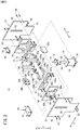
- the clamp device 10 clamps workpieces W1 and W2 between a pair (plurality) of clamp arms 16a, 16b, and is applied to, for example, a welding process of an automatic assembly line of the machine industry or the like .
- the clamp device 10 includes a clamp body 12, a driving unit 14 provided on the clamp body 12, a pair of right and left clamp arms 16a, 16b movably provided on the clamp body 12, and a driving force transmission mechanism 18 that transmits a driving force of the driving unit 14 to the respective clamp arms 16a, 16b.
- the width direction of the clamp device 10 (the direction in which the clamp arms 16a, 16b are arranged) is the X direction
- the direction perpendicular to the X direction and the longitudinal direction of the clamp device 10 is the Y direction
- the direction perpendicular to the X direction and the Y direction is taken as the Z direction.
- the downward direction in FIG. 1 is defined as the Y1 direction
- the upward direction in FIG. 1 is defined as the Y2 direction.
- the clamp body 12 includes a pair of T-shaped plate bodies 20, 22 arranged substantially parallel to each other, while being spaced apart from each other by a predetermined distance; a base portion 24 connecting the narrow end portions of the plate bodies 20, 22; a pair of right and left connecting portions 26a, 26b for connecting the side portions of the plate bodies 20, 22 to each other; and a workpiece placement part 28 for connecting wide other ends of the plate bodies 20, 22 to each other.
- Elongated holes (guide portions) 30, 32 are formed along the longitudinal direction (Y direction) at substantially the center in the width direction (X direction) of the plate bodies 20, 22.
- the base portion 24 is formed in a flat plate shape, one side surface of which is fastened to the substantially central portion in the width direction of a narrow portion 34 of the plate body 20 by screws 36, and the other side surface is fastened to the substantially central portion in the width direction of a narrow portion 38 of the plate body 22 by screws 40. Further, the base portion 24 is fixed to a floor surface or the like, for example, by unillustrated bolts or the like.
- each of the connecting portions 26a, 26b is fastened to a substantially central portion of a wide portion 42 of the plate body 20 in the Y direction by screws 44.
- the other side surface is fastened to the center portion in the Y direction of a wide portion 46 of the plate body 22 by screws 48. That is, the connecting portion 26a and the connecting portion 26b are opposed to each other in the X direction.
- a projecting portion 50a is formed along the entire length in the Y direction.
- An inclined surface 52a that is inclined to the outer surface side of the connecting portion 26a toward the Y2 direction is formed at an end of the distal end surfaces of the projecting portion 50a in the Y2 direction.
- the connecting portion 26b has the same structure as the connecting portion 26a, and the projecting portion 50b and the inclined surface 52b are formed.
- the workpiece placement part 28 is a flat plate body on which the workpiece W1 is placed, and is fastened to the wide portions 42, 46 substantially at the center thereof in the X direction by screws 54.
- the driving unit 14 is configured as a fluid pressure cylinder (actuator). As shown in FIG. 5 , the driving unit 14 includes a cylinder tube 56, an end block 58 that closes an opening in one end side (Y1 direction) of the cylinder tube 56, a piston 60 displaceably arranged along the axial direction inside the cylinder tube 56, a piston rod (displacement body) 62 connected to the piston 60, and a rod cover 64 supporting the piston rod 62 displaceably while blocking an opening in the other end side (Y2 direction) of the cylinder tube 56.
- the structure of the driving unit 14 is not particularly limited, and various mechanisms capable of linearly displacing the displacement body may be applied. For example, a linear electric actuator including a ball screw actuator or the like can be adopted as the driving unit.
- the cylinder tube 56 is disposed between the narrow portions 34, 38 of the pair of plate bodies 20, 22 (see FIG. 1 ).
- a first port and a second port (not shown) for supplying and discharging compressed fluid (driving fluid) are formed in the cylinder tube 56.
- the pair of clamp arms 16a, 16b are located between the pair of connecting portions 26a, 26b and are spaced apart from each other by a predetermined distance in the X direction.
- the clamp arm 16a is formed in a quadrangular prism shape. One end portion of the clamp arm 16a bulges to both sides in the X direction.
- a gripping surface 66a contacting the workpieces W1, W2 is formed.
- the clamp arm 16b is configured similarly to the clamp arm 16a, and a gripping surface 66b is formed at the other end portion thereof.
- the driving force transmission mechanism 18 includes a pair of movable plates (movable parts) 68, 70 arranged to be spaced apart from each other in the Z direction, a first connecting portion 72 connecting ends of the pair of movable plates 68, 70 in the Y1 direction in a state of being connected to the piston rod 62, a second connecting portion 74 connecting ends of the pair of movable plates 68, 70 in the Y2 direction, and a pair of fixed plates (fixed parts) 76, 78 which are arranged inward of the pair of movable plates 68, 70 in the Z direction with a gap between the fixed plates 76, 78.
- the movable plate 68 and the fixed plate 76 are disposed between the pair of clamp arms 16a, 16b and the wide portion 42, and the movable plate 70 and the fixed plate 78 are disposed between the pair of clamp arms 16a, 16b and the wide portion 46. Further, the movable plates 68, 70 and the fixed plates 76, 78 extend in the X direction in a state parallel to the wide portions 42, 46.
- the movable plate 68 is configured in the same manner as the movable plate 70
- the fixed plate 76 is configured in the same manner as the fixed plate 78. Therefore, in the following, the configurations of the movable plate 68 and the fixed plate 76 will be described, and the description of the configurations of the movable plate 70 and the fixed plate 78 will be omitted.
- a first arrangement portion 80 recessed so as to arrange the first connection portion 72 and a second arrangement portion 82 recessed so as to arrange the second connection portion 74 are formed.
- a slide portion 84 extending along the Y direction is fastened by screws 86 to the surface of the movable plate 68 facing the wide portion 42.
- the slide portion 84 is disposed slidably in the elongated hole 30 of the plate body 20 along the Y direction.
- the movable plate 68 has a pair of first cam holes 88a, 88b formed substantially symmetrically with respect to the centerline (first axis of symmetry) CL1 in the X direction thereof.
- the first cam hole 88a is formed of a first hole portion 90a having an end portion 91a in the vicinity of the outer corner portion of the movable plate 68 in the Y1 direction and extending from the end portion 91a toward the inner side in the X direction (toward the centerline CL1) and inclined in the Y2 direction, and a second hole portion 92a extending from the innermost position of the first hole portion 90a in the X direction in the Y2 direction and inclined toward the inner side in the X direction.
- the first hole portion 90a is formed to be shorter than the second hole portion 92a.
- the inner surface 93a on the outer side of the second hole portion 92a is inclined at a predetermined inclined surface angle ⁇ with respect to the imaginary line IL in the Y direction and functions as a wedge working surface for guiding the first roller 116a described later.
- the first cam hole 88b is configured similarly to the first cam hole 88a and includes a first hole portion 90b having an end portion 91b and a second hole portion 92b having an inner surface 93b.
- the first connecting portion 72 is a flat plate member extending in the Z direction, and the piston rod 62 is fastened to the substantially center in the Z direction by a screw 94. Both end portions of the first connecting portion 72 are formed to be narrower than the central portion thereof and are fastened by screws 96 in a state of being disposed in the first arrangement portions 80 of the movable plates 68, 70.
- the second connecting portion 74 is a flat plate-shaped member extending along the Z direction. Both end portions of the second connecting portion 74 are formed to be narrower than the central portion thereof and fastened by screws 98 in a state of being disposed on the second arrangement portion 82 of the movable plates 68, 70.
- Both ends of the fixed plates 76, 78 in the X direction are fastened to the projecting portions 50a, 50b by screws 100, so that the fixed plates 76, 78 are fixed to the clamp body 12.
- a first recessed portion 102 into which the first connecting portion 72 can be inserted and a second recessed portion 104 into which the second connecting portion 74 can be inserted are formed substantially in the center in the X direction of the fixed plates 76, 78. This prevents the first connecting portion 72 and the second connecting portion 74 from interfering with the fixed plates 76, 78 when the movable plates 68, 70 are displaced in the Y direction with respect to the fixed plates 76, 78.
- the fixed plate 76 has a pair of second cam holes 106a, 106b formed substantially symmetrically with respect to the centerline (second axis of symmetry) CL2 in the X direction.
- a part of the second cam hole 106a is formed so as to overlap a part of the first cam hole 88a in plan view (front view) from the Z direction (see FIGS. 5 to 7 ). The same applies to the second cam hole 106b.
- the second cam hole 106a is formed of a third hole portion 108a extending from the vicinity of the outer corner portion of the fixed plate 76 in the Y1 direction toward the inner side in the X direction (toward the centerline CL2) and inclined in the Y2 direction, and a fourth hole portion 110a extending along the X direction from the innermost position of the three hole portion 108a in the X direction inside.
- the third hole portion 108a is set to be substantially the same length as the fourth hole portion 110a.
- the second cam hole 106b is configured similarly to the second cam hole 106a, and has a third hole portion 108b and a fourth hole portion 110b.
- the driving force transmission mechanism 18 includes a first shaft 112a and a second shaft 114a provided (fixed) so as to penetrate through one end of the clamp arm 16a in the Z direction, a first roller 116a rotatably provided on the first shaft 112a and moving in the first cam holes 88a of the movable plates 68, 70, a second roller 118a rotatably provided on the first shaft 112a and moving in the second cam holes 106a of the fixed plates 76, 78, and a third roller 120a rotatably provided on the second shaft 114a and moving in the second cam holes 106a of the fixed plates 76, 78.
- the first shaft 112a is located on the inner side in the X direction (the side on which the clamp arm 16b is positioned) than the second shaft 114a and is longer than the second shaft 114a.
- the first shaft 112a extends at both sides of the clamp arm 16a in the Z direction in a state of being provided at one end portion of the clamp arm 16a, and the first roller 116a and the second roller 118a are provided on the first shaft 112a at each side of the portions extending.
- the second shaft 114a extends at both sides of the clamp arm 16a in the Z direction in a state of being provided at one end portion of the clamp arm 16a, and the third roller 120a is provided on the second shaft 114a at each side of the portions extending.
- the first shaft 112a and the second shaft 114a are provided with holding members 122a (see FIG. 3 ) for holding the axial positions of the first to third rollers 116a, 118a, and 120a.
- the driving force transmission mechanism 18 includes a first shaft 112b and a second shaft 114b (fixed) provided so as to penetrate through one end portion of the clamp arm 16b in the Z direction, a first roller 116b rotatably provided on the first shaft 112b and moving in the first cam holes 88b of the movable plate 68, 70, a second roller 118b rotatably provided on the first shaft 112b and moving in the second cam holes 106b of the fixed plates 76, 78, and a third roller 120b rotatably provided on the second shaft 114b and moving in the second cam holes 106b of the fixed plates 76, 78.
- the first shaft 112b, the second shaft 114b, the first to third rollers 116b, 118b, and 120b are similar in structure to those provided on the clamp arm 16a, and therefore description thereof is omitted. Note that holding members 122b (see FIG. 3 ) is provided on the first shaft 112b and the second shaft 114b.
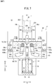
- the clamp device 10 is basically configured as described above. Next, the operation and effects thereof will be described. In the following description, the unclamping state in which the gripping surfaces 66a, 66b of the pair of clamp arms 16a, 16b shown in FIG. 5 are maximally separated from each other will be described as an initial position.
- the first rollers 116a, 116b are positioned on the outermost side in the X direction in the first hole portions 90a, 90b. Further, the second rollers 118a, 118b are positioned at the boundaries between the third hole portions 108a, 108b and the fourth hole portions 110a, 110b, and the third rollers 120a, 120b are positioned at the fourth hole portions 110a, 110b.
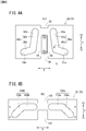
- This workpiece W1 is composed of a first frame 200 having a U-shaped cross section and a second frame 202 having a U-shaped cross section combined with the first frame 200.
- the first frame 200 opens toward the Y2 direction, and both sidewalls 204 are inclined so as to gradually widen outward in the X direction toward the Y2 direction.
- the second frame 202 is disposed in the opening of the first frame 200 in a state of being open toward the Y1 direction.
- the workpiece W1 is supplied (conveyed) to the workpiece placement part 28 of the clamp device 10 by a conveying device or the like of the automatic assembly line.
- the distance between the gripping surface 66a of the clamp arm 16a and the gripping surface 66b of the clamp arm 16b is considerably larger than the width dimension of the workpiece placement part 28, and the clamp arms 16a, 16b are advanced in the Y1 direction than the workpiece placement surface of the workpiece placement part 28.
- the clamp arms 16a, 16b do not protrude from the workpiece placement surface of the workpiece placement part 28 in the Y2 direction. Therefore, it is possible to smoothly supply the workpiece W1 to the workpiece placement part 28 without interfering with the clamp arms 16a, 16b.
- the piston 60 is displaced toward the end block 58 under the action of the compressed fluid. Then, since the piston rod 62 is displaced in the Y1 direction, the movable plates 68, 70 are displaced in the Y1 direction while the slide portions 84 provided on the respective movable plates 68, 70 are guided by the elongated holes 30, 32.
- the first roller 116a rolls (runs) on the wall surface constituting the first hole portion 90a toward the second hole portion 92a
- the second roller 118a rolls on the wall surface constituting the fourth hole portion 110a inward in the X direction
- the third roller 120a rolls on the wall surface constituting the third hole portion 108a toward the fourth hole portion 110a.
- the operations of the first to third rollers 116a, 118a, and 120a and the operations of the first to third rollers 116b, 118b, and 120b are the same as the movements of the movable plates 68, 70. Therefore, here, the operation of the first to third rollers 116a, 118a, and 120a will be mainly described, and the explanation of the operation of the first to third rollers 116b, 118b and 120b will be omitted.
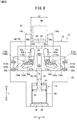
- the pair of clamp arms 16a, 16b move inward in the X direction (in directions approaching each other), and the gripping surfaces 66a, 66b are rotated so as to be parallel to the Y direction (see FIG. 6 ).
- the clamp arm 16a rotates in the counterclockwise direction while moving to the side where the clamp arm 16b is located, and the clamp arm 16b rotates in the clockwise direction while moving to the side where the clamp arm 16a is located.
- the first roller 116a is positioned at the boundary between the first hole portion 90a and the second hole portion 92a
- the second roller 118a is positioned slightly inward from the center of the fourth hole portion 110a in the X direction
- the third roller 120a is positioned at the boundary between the third hole portion 108a and the fourth hole portion 110a.
- the gripping surfaces 66a, 66b contact the sidewalls 204 of the first frame 200.
- the pair of clamp arms 16a, 16b move in parallel in the X direction while pressing the sidewalls 204 of the first frame 200. That is, while maintaining the parallel state of the gripping surface 66a and the gripping surface 66b, the gap (clamp distance) between the gripping surface 66a and the gripping surface 66b is narrowed. At this time, the inner surfaces 93a, 93b outside the second hole portions 92a, 92b are inclined at the inclined surface angle ⁇ (see FIG. 4A ).
- the clamping interval can be changed within a predetermined range while holding the parallel state of the gripping surface 66a and the gripping surface 66b. Therefore, for example, even in the case of clamping the workpiece W2 having the width dimension L2 larger than the width dimension L1 of the workpiece W1 shown in FIG. 7 , the gripping surfaces 66a, 66b reliably and stably clamp the workpiece W2 (see FIG. 8 ), avoiding one side abutment.
- the clamp arms 16a, 16b press and grasp the workpiece W2 by a wedge action in which the clamp arms 16a, 16b are translated in a direction to approach each other.
- the piston 60 when releasing (unclamping) the clamp of the workpiece W1, the piston 60 is displaced toward the rod cover 64 under the action of the compressed fluid. Then, since the piston rod 62 and the movable plates 68, 70 are displaced in the Y2 direction, the pair of clamp arms 16a, 16b are translated in a direction to separate from each other (outward in the X direction) while maintaining the parallel state (see FIG. 6 ). As the piston 60 is further displaced toward the rod cover 64, the pair of clamp arms 16a, 16b move outward in the X direction and rotate so that the gripping surfaces 66a, 66b are apart from each other (see FIG. 5 ).
- the rotation of the clamp arms 16a, 16b may be stopped such that, for example, in a state where they are not in contact with the inclined surfaces 52a and 52b, the first rollers 116a and 116b contact the wall surfaces constituting the first cam holes 88a, 88b (the end portions 91a and 91b of the first hole portions 90a and 90b).
- the driving force transmission mechanism 18 converts the linear motion of the piston 60 and the piston rod 62 into a first motion in which the pair of claim arms 16a, 16b rotate while moving toward and away from each other, and into a second motion in which the pair of clamp arms 16a, 16b are translated toward and away from each other in a state where the gripping surfaces 66a, 66b are parallel to each other.
- the clamp distance can be changed, it is possible to reliably and stably clamp plural types of workpieces W1, W2 having different widths while suppressing upsizing of the clamp device 10 with a simple configuration. Further, as the clamp arms 16a, 16b rotate, the distance between the gripping faces 66a, 66b in the unclamping state can be made relatively wide, so that the degree of freedom of the supply direction of the workpiece W1 can be increased.
- the first shaft 112a and the second shaft 114a are provided at one end portion of the clamp arm 16a, and the first shaft 112b and the second shaft 114b are provided at one end portion of the clamp arm 16b. Therefore, it is possible to prevent the end portions of the clamp arms 16a, 16b from interfering with each other in the unclamping state. Accordingly, since the maximum opening angle of the clamp arms 16a, 16b can be set relatively large, the degree of freedom in the supply direction and discharge direction of the workpieces W1, W2 can further be enhanced.
- the movable plate 68 (the movable plate 70), the fixed plate 76 (the fixed plate 78), the first rollers 116a, 116b, the second rollers 118a, 118b, and the third rollers 120a, 120b are provided on both sides in the Z direction of the clamp arms 16a, 16b in pairs.
- the first motion and the second motion of the clamp arms 16a, 16b can be performed more smoothly and stably.
- the slide portion 84 is guided by the elongated holes 30, 32 formed in the plate bodies 20, 22, so that the respective movable plates 68, 70 can be linearly moved smoothly. Therefore, the first motion and the second motion of the pair of clamp arms 16a, 16b can be performed more smoothly and stably.
- the clamp device 10 may have a plurality of clamp arms 16a, 16b according to the shape of the workpiece to be clamped or the like.
- the number of the clamp arms 16a and the number of the clamp arms 16b may be the same or different.
- the driving force transmission mechanism 18 can be dispensed with the movable plate 70, the fixed plate 78, the first roller 116a, 116b, the second roller 118a, 118b, and the third rollers 120a, 120b that are disposed between the clamp arms 16a, 16b and the plate body 22. Even in this case, the same action and effect as those of the above-described embodiment can be obtained.
Claims (6)
- Eine Spannvorrichtung (10) zum Spannen eines Werkstücks (W1, W2) zwischen mehreren Spannarmen (16a, 16b), mit:einem Spannkörper (12),mehreren Spannarmen (16a, 16b), die relativ zu dem Spannkörper (12) beweglich gehalten werden,einer Antriebseinheit (14) mit einem Verschiebungskörper (62) zur linear hin und her gehenden Bewegung, der an dem Spannkörper (12) angebracht ist, undeinem Antriebskraftübertragungsmechanismus (18), der dazu ausgestaltet ist, eine Antriebskraft von der Antriebseinheit (14) auf jeden der Spannarme (16a, 16b) zu übertragen,wobei der Antriebskraftübertragungsmechanismus (18) dazu ausgestaltet ist, die lineare Bewegung des Verschiebungskörpers (62) in eine erste Bewegung zum Bewegen und Drehen der mehreren Spannarme (16a, 16b) in einer Richtung zu oder weg voneinander und in eine zweite Bewegung zur translatorischen Bewegung der mehreren Spannarme (16a, 16b) in einer Richtung zu oder weg voneinander in einem Zustand, in dem die Greifflächen (66a, 66b) der jeweiligen Spannarme (16a, 16b) zur Berührung des Werkstücks (W1, W2) parallel zueinander verlaufen, umzuwandeln,dadurch gekennzeichnet, dass der Antriebskraftübertragungsmechanismus (18) folgendes aufweist:einen beweglichen Teil (68, 70), der an dem Verschiebungskörper (62) vorgesehen ist, eine erste Nockenöffnung (88a, 88b), die in dem beweglichen Teil (68, 70) ausgebildet ist,einen festen Teil (76, 78), der an dem Spannkörper (12) vorgesehen ist, eine zweite Nockenöffnung (106a, 106b), die in dem festen Teil (76, 78) ausgebildet ist,eine erste Welle (112a, 112b) und eine zweite Welle (114a, 114b), die für jeden der Spannarme (16a, 16b) vorgesehen sind,eine erste Walze (116a, 116b), die drehbar an der ersten Welle (112a, 112b) vorgesehen und in der ersten Nockenöffnung (88a, 88b) bewegbar ist,eine zweite Walze (118a, 118b), die drehbar an der ersten Welle (112a, 112b) vorgesehen und in der zweiten Nockenöffnung (106a, 106b) bewegbar ist, undeine dritte Walze (120a, 120b), die drehbar an der zweiten Welle (114a, 114b) vorgesehen und in der zweiten Nockenöffnung (106a, 106b) bewegbar ist,wobei der bewegliche Teil (68, 70) und der feste Teil (76, 78) so angeordnet sind, dass die erste Nockenöffnung (88a, 88b) und die zweite Nockenöffnung (106a, 106b) einander in der Draufsicht wenigstens teilweise überlappen.
- Die Spannvorrichtung (10) nach Anspruch 1, wobei die mehreren Spannarme (16a, 16b) als ein Paar vorgesehen sind,
wobei das Paar von Spannarmen (16a, 16b) ein Paar der ersten Nockenöffnungen (88a, 88b), die im Wesentlichen in einer seitlich symmetrischen Weise vorgesehen sind, und ein Paar zweiter Nockenöffnungen (106a, 106b), die im Wesentlichen in einer seitlich symmetrischen Weise symmetrisch vorgesehen sind, aufweist,
wobei jede der ersten Nockenöffnungen (88a, 88b) durch einen ersten Lochabschnitt (90a, 90b) und einen zweiten Lochabschnitt (92a, 92b) gebildet wird, wobei der erste Lochabschnitt (90a, 90b) sich zu einer ersten Symmetrieachse (CL1) des Paares erster Nockenöffnungen (88a, 88b) erstreckt, wobei er zu einer Seite einer Bewegungsrichtung des beweglichen Teils (68, 70) geneigt ist, und wobei sich der zweite Lochabschnitt (92a, 92b) von dem ersten Lochabschnitt (90a, 90b) zu der einen Seite einer Bewegungsrichtung des beweglichen Teils (68, 70) erstreckt, wobei er zu der ersten Symmetrieachse (CL1) geneigt ist,
wobei die zweiten Nockenöffnungen (106a, 106b) jeweils durch einen dritten Lochabschnitt (108a, 108b) und einen vierten Lochabschnitt (110a, 110b) gebildet werden, wobei der dritte Lochabschnitt (108a, 108b) sich zu einer zweiten Symmetrieachse (CL2) des Paares der zweiten Nockenöffnungen (106a, 106b) erstreckt, wobei er zu der einen Seite einer Bewegungsrichtung des beweglichen Teils (68, 70) geneigt ist, und wobei sich der vierte Lochabschnitt (110a, 110b) von dem dritten Lochabschnitt (108a, 108b) zu der zweiten Symmetrieachse (CL2) erstreckt. - Die Spannvorrichtung (10) nach Anspruch 1, wobei die erste Welle (112a, 112b) und die zweite Welle (114a, 114b) jeweils an einem Ende der Spannarme (16a, 16b) vorgesehen sind, die einer Seite entgegengesetzt sind, an der die Greifflächen (66a, 66b) angeordnet sind.
- Die Spannvorrichtung (10) nach Anspruch 1, wobei der bewegliche Teil (68, 70), der feste Teil (76, 78), die erste Walze (116a, 116b), die zweite Walze (118a, 118b) und die dritten Walzen (120a, 120b) an beiden Seiten des Spannarms (16a, 16b) paarweise angeordnet sind.
- Die Spannvorrichtung (10) nach Anspruch 1, wobei der bewegliche Teil (68, 70) einen Gleitabschnitt (84) aufweist,
wobei der Spannkörper (12) einen Führungsabschnitt (30, 32) aufweist, der dazu ausgestaltet ist, den Gleitabschnitt (84) entlang einer Bewegungsrichtung des Verschiebungskörpers (62) zu führen. - Die Spannvorrichtung nach Anspruch 1, außerdem mit einem Werkstückplatzierungsteil (28), auf dem das Werkstück (W1, W2) platziert wird,
wobei die Spannarme (16a, 16b) jeweils so angeordnet sind, dass die Spannarme (16a, 16b) in einem nicht klemmenden Zustand nicht von einer Werkstückplatzierungsfläche des Werkstückplatzierungsteils (28) zu einer Seite vorstehen, an der das Werkstück (W1, W2) angeordnet ist.
Applications Claiming Priority (2)
| Application Number | Priority Date | Filing Date | Title |
|---|---|---|---|
| JP2015089697A JP6355054B2 (ja) | 2015-04-24 | 2015-04-24 | クランプ装置 |
| PCT/JP2016/050108 WO2016170802A1 (ja) | 2015-04-24 | 2016-01-05 | クランプ装置 |
Publications (3)
| Publication Number | Publication Date |
|---|---|
| EP3287230A1 EP3287230A1 (de) | 2018-02-28 |
| EP3287230A4 EP3287230A4 (de) | 2018-12-26 |
| EP3287230B1 true EP3287230B1 (de) | 2021-03-10 |
Family
ID=57143009
Family Applications (1)
| Application Number | Title | Priority Date | Filing Date |
|---|---|---|---|
| EP16782824.3A Active EP3287230B1 (de) | 2015-04-24 | 2016-01-05 | Spannvorrichtung |
Country Status (7)
| Country | Link |
|---|---|
| US (1) | US10549394B2 (de) |
| EP (1) | EP3287230B1 (de) |
| JP (1) | JP6355054B2 (de) |
| CN (1) | CN107530850B (de) |
| BR (1) | BR112017022533B1 (de) |
| MX (1) | MX2017013568A (de) |
| WO (1) | WO2016170802A1 (de) |
Families Citing this family (15)
| Publication number | Priority date | Publication date | Assignee | Title |
|---|---|---|---|---|
| JP6939196B2 (ja) * | 2017-07-27 | 2021-09-22 | 日本精工株式会社 | 把持装置 |
| JP6848753B2 (ja) * | 2017-07-27 | 2021-03-24 | 日本精工株式会社 | 把持装置 |
| JP6907782B2 (ja) * | 2017-07-27 | 2021-07-21 | 日本精工株式会社 | 把持装置 |
| CN108908908B (zh) * | 2018-06-25 | 2023-08-08 | 苏州富强科技有限公司 | 一种壳体整形机构 |
| JP6725595B2 (ja) * | 2018-06-28 | 2020-07-22 | ファナック株式会社 | クランプ装置 |
| CN110116320A (zh) * | 2019-05-08 | 2019-08-13 | 鸿泰佛吉亚复合材料(武汉)有限公司 | 一种开花式夹紧装置 |
| ES2899073T3 (es) * | 2019-05-20 | 2022-03-10 | Smw Autoblok Spannsysteme Gmbh | Dispositivo de sujeción de punto cero |
| JP7470529B2 (ja) * | 2020-02-21 | 2024-04-18 | コマツNtc株式会社 | 電池製造用搬送治具 |
| CN111906342A (zh) * | 2020-08-05 | 2020-11-10 | 重庆赛普机电有限责任公司 | 一种毛刺清理机 |
| CN112722150B (zh) * | 2020-12-24 | 2023-06-09 | 徐州燕大传动与控制技术有限公司 | 一种船载可移动夹持装置及使用方法 |
| JP7052896B2 (ja) * | 2021-03-04 | 2022-04-12 | 日本精工株式会社 | 把持装置 |
| CN113211124B (zh) * | 2021-05-06 | 2022-06-10 | 扬州工业职业技术学院 | 一种用于建筑物料的同步式切割装置 |
| CN113715043B (zh) * | 2021-08-12 | 2022-12-20 | 中国核电工程有限公司 | 一种夹持机构和自动卸料装置 |
| US20230271299A1 (en) * | 2022-02-25 | 2023-08-31 | Arobotech Systems, Inc. | Finely adjustable steady rest system |
| CN116900768B (zh) * | 2023-09-11 | 2024-01-12 | 成都飞机工业(集团)有限责任公司 | 一种模块式柔性工装及其使用方法 |
Family Cites Families (19)
| Publication number | Priority date | Publication date | Assignee | Title |
|---|---|---|---|---|
| US4518187A (en) * | 1983-06-06 | 1985-05-21 | Leland F. Blatt | Parallel movement gripper head |
| JPS60178592U (ja) * | 1984-05-02 | 1985-11-27 | 大福工営株式会社 | チヤツキング装置 |
| US4650237A (en) * | 1985-07-25 | 1987-03-17 | Arobotech Systems, Inc. | Automatic centering and gripper apparatus |
| US6115898A (en) * | 1995-06-06 | 2000-09-12 | Btm Corporation | Force multiplying apparatus for clamping a workpiece and forming a joint therein |
| JP3877822B2 (ja) * | 1996-12-27 | 2007-02-07 | 株式会社松浦機械製作所 | ツールマガジン用ツール抜き |
| DE29718643U1 (de) * | 1997-10-21 | 1997-12-11 | Tuenkers Maschinenbau Gmbh | Druckmittelbetätigbare kombinierte Zentrier- und Spannvorrichtung, insbesondere zur Verwendung im Karosseriebau der Kfz-Industrie |
| US6079896A (en) * | 1998-01-07 | 2000-06-27 | Isi Norgren, Inc. | Clamp with improved internal cam action |
| JP3634190B2 (ja) * | 1999-05-24 | 2005-03-30 | Smc株式会社 | クランプ装置 |
| US6290210B1 (en) * | 1999-06-01 | 2001-09-18 | Aladdin Engineering & Manufacturing | Clamping and lifting mechanism |
| US6634630B2 (en) * | 1999-06-01 | 2003-10-21 | Aladdin Engineering & Manufacturing | Clamping and lifting mechanism |
| US6530615B2 (en) * | 2001-01-17 | 2003-03-11 | Syron Engineering & Mfg., Llc | Workpiece gripper |
| US6908077B2 (en) * | 2002-09-26 | 2005-06-21 | Btm Corporation | Clamp with swinging and linear motion |
| JP2005153123A (ja) | 2003-11-28 | 2005-06-16 | Kinugawa Rubber Ind Co Ltd | グリッパ装置とそのグリッパ装置を用いたワーク搬送装置 |
| JP2009012138A (ja) | 2007-07-06 | 2009-01-22 | Toyota Motor Corp | ワーク把持ロボット及びワークの把持方法 |
| JP5418997B2 (ja) * | 2008-01-22 | 2014-02-19 | Smc株式会社 | クランプ装置 |
| JP4950123B2 (ja) | 2008-05-21 | 2012-06-13 | シーケーディ株式会社 | クランプ装置 |
| JP5962684B2 (ja) * | 2013-01-28 | 2016-08-03 | Smc株式会社 | クランプ装置 |
| JP5942126B2 (ja) | 2013-07-18 | 2016-06-29 | Smc株式会社 | クランプ装置 |
| JP6302340B2 (ja) * | 2014-04-23 | 2018-03-28 | Thk株式会社 | 把持装置 |
-
2015
- 2015-04-24 JP JP2015089697A patent/JP6355054B2/ja active Active
-
2016
- 2016-01-05 US US15/568,669 patent/US10549394B2/en active Active
- 2016-01-05 BR BR112017022533-6A patent/BR112017022533B1/pt active IP Right Grant
- 2016-01-05 WO PCT/JP2016/050108 patent/WO2016170802A1/ja active Application Filing
- 2016-01-05 CN CN201680022755.9A patent/CN107530850B/zh active Active
- 2016-01-05 EP EP16782824.3A patent/EP3287230B1/de active Active
- 2016-01-05 MX MX2017013568A patent/MX2017013568A/es unknown
Non-Patent Citations (1)
| Title |
|---|
| None * |
Also Published As
| Publication number | Publication date |
|---|---|
| CN107530850A (zh) | 2018-01-02 |
| CN107530850B (zh) | 2019-09-27 |
| BR112017022533B1 (pt) | 2022-11-16 |
| EP3287230A1 (de) | 2018-02-28 |
| JP2016203327A (ja) | 2016-12-08 |
| US20180141176A1 (en) | 2018-05-24 |
| WO2016170802A1 (ja) | 2016-10-27 |
| US10549394B2 (en) | 2020-02-04 |
| JP6355054B2 (ja) | 2018-07-11 |
| BR112017022533A2 (pt) | 2018-07-10 |
| MX2017013568A (es) | 2018-02-09 |
| EP3287230A4 (de) | 2018-12-26 |
Similar Documents
| Publication | Publication Date | Title |
|---|---|---|
| EP3287230B1 (de) | Spannvorrichtung | |
| US6530615B2 (en) | Workpiece gripper | |
| EP2882571B1 (de) | Klemmvorrichtung | |
| EP1004410B1 (de) | Einstellbare Stoppers zur begrenzung des Öffnungswinkels eines Greifers | |
| CN109956318A (zh) | 工件固定夹具、工件输送装置及机器人系统 | |
| CN110636925B (zh) | 工件夹持装置 | |
| CN108529209B (zh) | 一种物件夹持装置 | |
| US11612925B2 (en) | Bending machine and method for bending a workpiece out of a flat material | |
| KR20180071462A (ko) | 형강재 비틀림가공 장치 | |
| WO2019180786A1 (ja) | 曲げ加工装置 | |
| EP3981546A1 (de) | Pneumatische spannvorrichtung für platten mit kippklauen | |
| JP5943237B2 (ja) | クランプ装置 | |
| WO2018211867A1 (en) | Workpiece gripping device | |
| JP2022501203A (ja) | 異なるタングスタイルを有する工具に使用可能な工具ホルダ、及び当該ホルダの着座/固定部品 | |
| CN108290262B (zh) | 工件移送装置 | |
| WO2023223411A1 (ja) | ワーク自動搬送機 | |
| CN113798538B (zh) | 多工位钻孔设备 | |
| CN110434880B (zh) | 夹具及移料机器人 | |
| KR101283131B1 (ko) | 파이프의 측면가공기용 파이프공급장치 | |
| JP2012016753A (ja) | 平行開閉式チャックハンド |
Legal Events
| Date | Code | Title | Description |
|---|---|---|---|
| STAA | Information on the status of an ep patent application or granted ep patent |
Free format text: STATUS: THE INTERNATIONAL PUBLICATION HAS BEEN MADE |
|
| PUAI | Public reference made under article 153(3) epc to a published international application that has entered the european phase |
Free format text: ORIGINAL CODE: 0009012 |
|
| STAA | Information on the status of an ep patent application or granted ep patent |
Free format text: STATUS: REQUEST FOR EXAMINATION WAS MADE |
|
| 17P | Request for examination filed |
Effective date: 20171101 |
|
| AK | Designated contracting states |
Kind code of ref document: A1 Designated state(s): AL AT BE BG CH CY CZ DE DK EE ES FI FR GB GR HR HU IE IS IT LI LT LU LV MC MK MT NL NO PL PT RO RS SE SI SK SM TR |
|
| AX | Request for extension of the european patent |
Extension state: BA ME |
|
| DAV | Request for validation of the european patent (deleted) | ||
| DAX | Request for extension of the european patent (deleted) | ||
| A4 | Supplementary search report drawn up and despatched |
Effective date: 20181128 |
|
| RIC1 | Information provided on ipc code assigned before grant |
Ipc: B25B 5/06 20060101ALI20181121BHEP Ipc: B23Q 3/06 20060101AFI20181121BHEP Ipc: B25B 5/08 20060101ALI20181121BHEP |
|
| GRAP | Despatch of communication of intention to grant a patent |
Free format text: ORIGINAL CODE: EPIDOSNIGR1 |
|
| STAA | Information on the status of an ep patent application or granted ep patent |
Free format text: STATUS: GRANT OF PATENT IS INTENDED |
|
| INTG | Intention to grant announced |
Effective date: 20200820 |
|
| RIN1 | Information on inventor provided before grant (corrected) |
Inventor name: FUKUI, CHIAKI Inventor name: TAKAHASHI, KAZUYOSHI Inventor name: SEO, TAKESHI |
|
| GRAS | Grant fee paid |
Free format text: ORIGINAL CODE: EPIDOSNIGR3 |
|
| STAA | Information on the status of an ep patent application or granted ep patent |
Free format text: STATUS: GRANT OF PATENT IS INTENDED |
|
| GRAA | (expected) grant |
Free format text: ORIGINAL CODE: 0009210 |
|
| STAA | Information on the status of an ep patent application or granted ep patent |
Free format text: STATUS: THE PATENT HAS BEEN GRANTED |
|
| AK | Designated contracting states |
Kind code of ref document: B1 Designated state(s): AL AT BE BG CH CY CZ DE DK EE ES FI FR GB GR HR HU IE IS IT LI LT LU LV MC MK MT NL NO PL PT RO RS SE SI SK SM TR |
|
| REG | Reference to a national code |
Ref country code: GB Ref legal event code: FG4D |
|
| REG | Reference to a national code |
Ref country code: AT Ref legal event code: REF Ref document number: 1369287 Country of ref document: AT Kind code of ref document: T Effective date: 20210315 Ref country code: CH Ref legal event code: EP |
|
| REG | Reference to a national code |
Ref country code: IE Ref legal event code: FG4D |
|
| REG | Reference to a national code |
Ref country code: DE Ref legal event code: R096 Ref document number: 602016054067 Country of ref document: DE |
|
| REG | Reference to a national code |
Ref country code: LT Ref legal event code: MG9D |
|
| PG25 | Lapsed in a contracting state [announced via postgrant information from national office to epo] |
Ref country code: HR Free format text: LAPSE BECAUSE OF FAILURE TO SUBMIT A TRANSLATION OF THE DESCRIPTION OR TO PAY THE FEE WITHIN THE PRESCRIBED TIME-LIMIT Effective date: 20210310 Ref country code: GR Free format text: LAPSE BECAUSE OF FAILURE TO SUBMIT A TRANSLATION OF THE DESCRIPTION OR TO PAY THE FEE WITHIN THE PRESCRIBED TIME-LIMIT Effective date: 20210611 Ref country code: FI Free format text: LAPSE BECAUSE OF FAILURE TO SUBMIT A TRANSLATION OF THE DESCRIPTION OR TO PAY THE FEE WITHIN THE PRESCRIBED TIME-LIMIT Effective date: 20210310 Ref country code: NO Free format text: LAPSE BECAUSE OF FAILURE TO SUBMIT A TRANSLATION OF THE DESCRIPTION OR TO PAY THE FEE WITHIN THE PRESCRIBED TIME-LIMIT Effective date: 20210610 Ref country code: LT Free format text: LAPSE BECAUSE OF FAILURE TO SUBMIT A TRANSLATION OF THE DESCRIPTION OR TO PAY THE FEE WITHIN THE PRESCRIBED TIME-LIMIT Effective date: 20210310 Ref country code: BG Free format text: LAPSE BECAUSE OF FAILURE TO SUBMIT A TRANSLATION OF THE DESCRIPTION OR TO PAY THE FEE WITHIN THE PRESCRIBED TIME-LIMIT Effective date: 20210610 |
|
| REG | Reference to a national code |
Ref country code: AT Ref legal event code: MK05 Ref document number: 1369287 Country of ref document: AT Kind code of ref document: T Effective date: 20210310 |
|
| REG | Reference to a national code |
Ref country code: NL Ref legal event code: MP Effective date: 20210310 |
|
| PG25 | Lapsed in a contracting state [announced via postgrant information from national office to epo] |
Ref country code: SE Free format text: LAPSE BECAUSE OF FAILURE TO SUBMIT A TRANSLATION OF THE DESCRIPTION OR TO PAY THE FEE WITHIN THE PRESCRIBED TIME-LIMIT Effective date: 20210310 Ref country code: RS Free format text: LAPSE BECAUSE OF FAILURE TO SUBMIT A TRANSLATION OF THE DESCRIPTION OR TO PAY THE FEE WITHIN THE PRESCRIBED TIME-LIMIT Effective date: 20210310 Ref country code: LV Free format text: LAPSE BECAUSE OF FAILURE TO SUBMIT A TRANSLATION OF THE DESCRIPTION OR TO PAY THE FEE WITHIN THE PRESCRIBED TIME-LIMIT Effective date: 20210310 |
|
| PG25 | Lapsed in a contracting state [announced via postgrant information from national office to epo] |
Ref country code: NL Free format text: LAPSE BECAUSE OF FAILURE TO SUBMIT A TRANSLATION OF THE DESCRIPTION OR TO PAY THE FEE WITHIN THE PRESCRIBED TIME-LIMIT Effective date: 20210310 |
|
| PG25 | Lapsed in a contracting state [announced via postgrant information from national office to epo] |
Ref country code: CZ Free format text: LAPSE BECAUSE OF FAILURE TO SUBMIT A TRANSLATION OF THE DESCRIPTION OR TO PAY THE FEE WITHIN THE PRESCRIBED TIME-LIMIT Effective date: 20210310 Ref country code: EE Free format text: LAPSE BECAUSE OF FAILURE TO SUBMIT A TRANSLATION OF THE DESCRIPTION OR TO PAY THE FEE WITHIN THE PRESCRIBED TIME-LIMIT Effective date: 20210310 Ref country code: SM Free format text: LAPSE BECAUSE OF FAILURE TO SUBMIT A TRANSLATION OF THE DESCRIPTION OR TO PAY THE FEE WITHIN THE PRESCRIBED TIME-LIMIT Effective date: 20210310 Ref country code: AT Free format text: LAPSE BECAUSE OF FAILURE TO SUBMIT A TRANSLATION OF THE DESCRIPTION OR TO PAY THE FEE WITHIN THE PRESCRIBED TIME-LIMIT Effective date: 20210310 |
|
| PG25 | Lapsed in a contracting state [announced via postgrant information from national office to epo] |
Ref country code: IS Free format text: LAPSE BECAUSE OF FAILURE TO SUBMIT A TRANSLATION OF THE DESCRIPTION OR TO PAY THE FEE WITHIN THE PRESCRIBED TIME-LIMIT Effective date: 20210710 Ref country code: SK Free format text: LAPSE BECAUSE OF FAILURE TO SUBMIT A TRANSLATION OF THE DESCRIPTION OR TO PAY THE FEE WITHIN THE PRESCRIBED TIME-LIMIT Effective date: 20210310 Ref country code: RO Free format text: LAPSE BECAUSE OF FAILURE TO SUBMIT A TRANSLATION OF THE DESCRIPTION OR TO PAY THE FEE WITHIN THE PRESCRIBED TIME-LIMIT Effective date: 20210310 Ref country code: PT Free format text: LAPSE BECAUSE OF FAILURE TO SUBMIT A TRANSLATION OF THE DESCRIPTION OR TO PAY THE FEE WITHIN THE PRESCRIBED TIME-LIMIT Effective date: 20210712 Ref country code: PL Free format text: LAPSE BECAUSE OF FAILURE TO SUBMIT A TRANSLATION OF THE DESCRIPTION OR TO PAY THE FEE WITHIN THE PRESCRIBED TIME-LIMIT Effective date: 20210310 |
|
| REG | Reference to a national code |
Ref country code: DE Ref legal event code: R097 Ref document number: 602016054067 Country of ref document: DE |
|
| PLBE | No opposition filed within time limit |
Free format text: ORIGINAL CODE: 0009261 |
|
| STAA | Information on the status of an ep patent application or granted ep patent |
Free format text: STATUS: NO OPPOSITION FILED WITHIN TIME LIMIT |
|
| PG25 | Lapsed in a contracting state [announced via postgrant information from national office to epo] |
Ref country code: DK Free format text: LAPSE BECAUSE OF FAILURE TO SUBMIT A TRANSLATION OF THE DESCRIPTION OR TO PAY THE FEE WITHIN THE PRESCRIBED TIME-LIMIT Effective date: 20210310 Ref country code: ES Free format text: LAPSE BECAUSE OF FAILURE TO SUBMIT A TRANSLATION OF THE DESCRIPTION OR TO PAY THE FEE WITHIN THE PRESCRIBED TIME-LIMIT Effective date: 20210310 Ref country code: AL Free format text: LAPSE BECAUSE OF FAILURE TO SUBMIT A TRANSLATION OF THE DESCRIPTION OR TO PAY THE FEE WITHIN THE PRESCRIBED TIME-LIMIT Effective date: 20210310 |
|
| 26N | No opposition filed |
Effective date: 20211213 |
|
| PG25 | Lapsed in a contracting state [announced via postgrant information from national office to epo] |
Ref country code: SI Free format text: LAPSE BECAUSE OF FAILURE TO SUBMIT A TRANSLATION OF THE DESCRIPTION OR TO PAY THE FEE WITHIN THE PRESCRIBED TIME-LIMIT Effective date: 20210310 |
|
| PG25 | Lapsed in a contracting state [announced via postgrant information from national office to epo] |
Ref country code: IT Free format text: LAPSE BECAUSE OF FAILURE TO SUBMIT A TRANSLATION OF THE DESCRIPTION OR TO PAY THE FEE WITHIN THE PRESCRIBED TIME-LIMIT Effective date: 20210310 |
|
| PG25 | Lapsed in a contracting state [announced via postgrant information from national office to epo] |
Ref country code: IS Free format text: LAPSE BECAUSE OF FAILURE TO SUBMIT A TRANSLATION OF THE DESCRIPTION OR TO PAY THE FEE WITHIN THE PRESCRIBED TIME-LIMIT Effective date: 20210710 |
|
| REG | Reference to a national code |
Ref country code: DE Ref legal event code: R119 Ref document number: 602016054067 Country of ref document: DE |
|
| PG25 | Lapsed in a contracting state [announced via postgrant information from national office to epo] |
Ref country code: MC Free format text: LAPSE BECAUSE OF FAILURE TO SUBMIT A TRANSLATION OF THE DESCRIPTION OR TO PAY THE FEE WITHIN THE PRESCRIBED TIME-LIMIT Effective date: 20210310 |
|
| REG | Reference to a national code |
Ref country code: CH Ref legal event code: PL |
|
| GBPC | Gb: european patent ceased through non-payment of renewal fee |
Effective date: 20220105 |
|
| REG | Reference to a national code |
Ref country code: BE Ref legal event code: MM Effective date: 20220131 |
|
| PG25 | Lapsed in a contracting state [announced via postgrant information from national office to epo] |
Ref country code: LU Free format text: LAPSE BECAUSE OF NON-PAYMENT OF DUE FEES Effective date: 20220105 Ref country code: DE Free format text: LAPSE BECAUSE OF NON-PAYMENT OF DUE FEES Effective date: 20220802 Ref country code: GB Free format text: LAPSE BECAUSE OF NON-PAYMENT OF DUE FEES Effective date: 20220105 |
|
| PG25 | Lapsed in a contracting state [announced via postgrant information from national office to epo] |
Ref country code: FR Free format text: LAPSE BECAUSE OF NON-PAYMENT OF DUE FEES Effective date: 20220131 Ref country code: BE Free format text: LAPSE BECAUSE OF NON-PAYMENT OF DUE FEES Effective date: 20220131 |
|
| PG25 | Lapsed in a contracting state [announced via postgrant information from national office to epo] |
Ref country code: LI Free format text: LAPSE BECAUSE OF NON-PAYMENT OF DUE FEES Effective date: 20220131 Ref country code: CH Free format text: LAPSE BECAUSE OF NON-PAYMENT OF DUE FEES Effective date: 20220131 |
|
| PG25 | Lapsed in a contracting state [announced via postgrant information from national office to epo] |
Ref country code: IE Free format text: LAPSE BECAUSE OF NON-PAYMENT OF DUE FEES Effective date: 20220105 |
|
| PG25 | Lapsed in a contracting state [announced via postgrant information from national office to epo] |
Ref country code: HU Free format text: LAPSE BECAUSE OF FAILURE TO SUBMIT A TRANSLATION OF THE DESCRIPTION OR TO PAY THE FEE WITHIN THE PRESCRIBED TIME-LIMIT; INVALID AB INITIO Effective date: 20160105 |