EP3285340A1 - Connector insert and cable - Google Patents
Connector insert and cable Download PDFInfo
- Publication number
- EP3285340A1 EP3285340A1 EP17194214.7A EP17194214A EP3285340A1 EP 3285340 A1 EP3285340 A1 EP 3285340A1 EP 17194214 A EP17194214 A EP 17194214A EP 3285340 A1 EP3285340 A1 EP 3285340A1
- Authority
- EP
- European Patent Office
- Prior art keywords
- shield
- cable
- connector insert
- circuit board
- printed circuit
- Prior art date
- Legal status (The legal status is an assumption and is not a legal conclusion. Google has not performed a legal analysis and makes no representation as to the accuracy of the status listed.)
- Withdrawn
Links
- 239000004020 conductor Substances 0.000 claims description 32
- 239000000835 fiber Substances 0.000 claims description 17
- 239000004760 aramid Substances 0.000 claims description 12
- 229920006231 aramid fiber Polymers 0.000 claims description 10
- 238000009954 braiding Methods 0.000 abstract description 22
- 229910000679 solder Inorganic materials 0.000 abstract description 20
- 229920003235 aromatic polyamide Polymers 0.000 abstract description 3
- 238000000034 method Methods 0.000 description 23
- 238000005476 soldering Methods 0.000 description 15
- 238000004519 manufacturing process Methods 0.000 description 6
- 238000002788 crimping Methods 0.000 description 5
- 238000004891 communication Methods 0.000 description 4
- 230000005611 electricity Effects 0.000 description 3
- 238000012986 modification Methods 0.000 description 3
- 230000004048 modification Effects 0.000 description 3
- 230000003068 static effect Effects 0.000 description 3
- 239000004677 Nylon Substances 0.000 description 2
- 230000008901 benefit Effects 0.000 description 2
- 238000010276 construction Methods 0.000 description 2
- 238000009413 insulation Methods 0.000 description 2
- 238000002955 isolation Methods 0.000 description 2
- 239000000463 material Substances 0.000 description 2
- 230000007246 mechanism Effects 0.000 description 2
- 229910052751 metal Inorganic materials 0.000 description 2
- 239000002184 metal Substances 0.000 description 2
- 229920001778 nylon Polymers 0.000 description 2
- 230000008569 process Effects 0.000 description 2
- 239000000758 substrate Substances 0.000 description 2
- 229920002799 BoPET Polymers 0.000 description 1
- RYGMFSIKBFXOCR-UHFFFAOYSA-N Copper Chemical compound [Cu] RYGMFSIKBFXOCR-UHFFFAOYSA-N 0.000 description 1
- 230000009471 action Effects 0.000 description 1
- 229910052782 aluminium Inorganic materials 0.000 description 1
- XAGFODPZIPBFFR-UHFFFAOYSA-N aluminium Chemical compound [Al] XAGFODPZIPBFFR-UHFFFAOYSA-N 0.000 description 1
- 238000007796 conventional method Methods 0.000 description 1
- 229910052802 copper Inorganic materials 0.000 description 1
- 239000010949 copper Substances 0.000 description 1
- 230000008878 coupling Effects 0.000 description 1
- 238000010168 coupling process Methods 0.000 description 1
- 238000005859 coupling reaction Methods 0.000 description 1
- 239000000428 dust Substances 0.000 description 1
- 230000017525 heat dissipation Effects 0.000 description 1
- 238000003780 insertion Methods 0.000 description 1
- 230000037431 insertion Effects 0.000 description 1
- 238000005304 joining Methods 0.000 description 1
- 239000007788 liquid Substances 0.000 description 1
- 239000004033 plastic Substances 0.000 description 1
- 238000007747 plating Methods 0.000 description 1
- 238000007789 sealing Methods 0.000 description 1
- 238000000926 separation method Methods 0.000 description 1
- 229910001220 stainless steel Inorganic materials 0.000 description 1
- 239000010935 stainless steel Substances 0.000 description 1
- 239000002470 thermal conductor Substances 0.000 description 1
- 238000012546 transfer Methods 0.000 description 1
Images


Classifications
-
- H—ELECTRICITY
- H01—ELECTRIC ELEMENTS
- H01R—ELECTRICALLY-CONDUCTIVE CONNECTIONS; STRUCTURAL ASSOCIATIONS OF A PLURALITY OF MUTUALLY-INSULATED ELECTRICAL CONNECTING ELEMENTS; COUPLING DEVICES; CURRENT COLLECTORS
- H01R13/00—Details of coupling devices of the kinds covered by groups H01R12/70 or H01R24/00 - H01R33/00
- H01R13/648—Protective earth or shield arrangements on coupling devices, e.g. anti-static shielding
- H01R13/658—High frequency shielding arrangements, e.g. against EMI [Electro-Magnetic Interference] or EMP [Electro-Magnetic Pulse]
- H01R13/6591—Specific features or arrangements of connection of shield to conductive members
- H01R13/6592—Specific features or arrangements of connection of shield to conductive members the conductive member being a shielded cable
-
- H—ELECTRICITY
- H01—ELECTRIC ELEMENTS
- H01R—ELECTRICALLY-CONDUCTIVE CONNECTIONS; STRUCTURAL ASSOCIATIONS OF A PLURALITY OF MUTUALLY-INSULATED ELECTRICAL CONNECTING ELEMENTS; COUPLING DEVICES; CURRENT COLLECTORS
- H01R12/00—Structural associations of a plurality of mutually-insulated electrical connecting elements, specially adapted for printed circuits, e.g. printed circuit boards [PCB], flat or ribbon cables, or like generally planar structures, e.g. terminal strips, terminal blocks; Coupling devices specially adapted for printed circuits, flat or ribbon cables, or like generally planar structures; Terminals specially adapted for contact with, or insertion into, printed circuits, flat or ribbon cables, or like generally planar structures
- H01R12/50—Fixed connections
- H01R12/51—Fixed connections for rigid printed circuits or like structures
- H01R12/53—Fixed connections for rigid printed circuits or like structures connecting to cables except for flat or ribbon cables
-
- H—ELECTRICITY
- H01—ELECTRIC ELEMENTS
- H01R—ELECTRICALLY-CONDUCTIVE CONNECTIONS; STRUCTURAL ASSOCIATIONS OF A PLURALITY OF MUTUALLY-INSULATED ELECTRICAL CONNECTING ELEMENTS; COUPLING DEVICES; CURRENT COLLECTORS
- H01R13/00—Details of coupling devices of the kinds covered by groups H01R12/70 or H01R24/00 - H01R33/00
- H01R13/646—Details of coupling devices of the kinds covered by groups H01R12/70 or H01R24/00 - H01R33/00 specially adapted for high-frequency, e.g. structures providing an impedance match or phase match
- H01R13/6461—Means for preventing cross-talk
- H01R13/6463—Means for preventing cross-talk using twisted pairs of wires
-
- H—ELECTRICITY
- H01—ELECTRIC ELEMENTS
- H01R—ELECTRICALLY-CONDUCTIVE CONNECTIONS; STRUCTURAL ASSOCIATIONS OF A PLURALITY OF MUTUALLY-INSULATED ELECTRICAL CONNECTING ELEMENTS; COUPLING DEVICES; CURRENT COLLECTORS
- H01R13/00—Details of coupling devices of the kinds covered by groups H01R12/70 or H01R24/00 - H01R33/00
- H01R13/646—Details of coupling devices of the kinds covered by groups H01R12/70 or H01R24/00 - H01R33/00 specially adapted for high-frequency, e.g. structures providing an impedance match or phase match
- H01R13/6461—Means for preventing cross-talk
- H01R13/6471—Means for preventing cross-talk by special arrangement of ground and signal conductors, e.g. GSGS [Ground-Signal-Ground-Signal]
-
- H—ELECTRICITY
- H01—ELECTRIC ELEMENTS
- H01R—ELECTRICALLY-CONDUCTIVE CONNECTIONS; STRUCTURAL ASSOCIATIONS OF A PLURALITY OF MUTUALLY-INSULATED ELECTRICAL CONNECTING ELEMENTS; COUPLING DEVICES; CURRENT COLLECTORS
- H01R13/00—Details of coupling devices of the kinds covered by groups H01R12/70 or H01R24/00 - H01R33/00
- H01R13/648—Protective earth or shield arrangements on coupling devices, e.g. anti-static shielding
- H01R13/658—High frequency shielding arrangements, e.g. against EMI [Electro-Magnetic Interference] or EMP [Electro-Magnetic Pulse]
-
- H—ELECTRICITY
- H01—ELECTRIC ELEMENTS
- H01R—ELECTRICALLY-CONDUCTIVE CONNECTIONS; STRUCTURAL ASSOCIATIONS OF A PLURALITY OF MUTUALLY-INSULATED ELECTRICAL CONNECTING ELEMENTS; COUPLING DEVICES; CURRENT COLLECTORS
- H01R4/00—Electrically-conductive connections between two or more conductive members in direct contact, i.e. touching one another; Means for effecting or maintaining such contact; Electrically-conductive connections having two or more spaced connecting locations for conductors and using contact members penetrating insulation
- H01R4/02—Soldered or welded connections
- H01R4/023—Soldered or welded connections between cables or wires and terminals
-
- H—ELECTRICITY
- H01—ELECTRIC ELEMENTS
- H01R—ELECTRICALLY-CONDUCTIVE CONNECTIONS; STRUCTURAL ASSOCIATIONS OF A PLURALITY OF MUTUALLY-INSULATED ELECTRICAL CONNECTING ELEMENTS; COUPLING DEVICES; CURRENT COLLECTORS
- H01R43/00—Apparatus or processes specially adapted for manufacturing, assembling, maintaining, or repairing of line connectors or current collectors or for joining electric conductors
- H01R43/02—Apparatus or processes specially adapted for manufacturing, assembling, maintaining, or repairing of line connectors or current collectors or for joining electric conductors for soldered or welded connections
- H01R43/0249—Apparatus or processes specially adapted for manufacturing, assembling, maintaining, or repairing of line connectors or current collectors or for joining electric conductors for soldered or welded connections for simultaneous welding or soldering of a plurality of wires to contact elements
-
- H—ELECTRICITY
- H01—ELECTRIC ELEMENTS
- H01R—ELECTRICALLY-CONDUCTIVE CONNECTIONS; STRUCTURAL ASSOCIATIONS OF A PLURALITY OF MUTUALLY-INSULATED ELECTRICAL CONNECTING ELEMENTS; COUPLING DEVICES; CURRENT COLLECTORS
- H01R43/00—Apparatus or processes specially adapted for manufacturing, assembling, maintaining, or repairing of line connectors or current collectors or for joining electric conductors
- H01R43/04—Apparatus or processes specially adapted for manufacturing, assembling, maintaining, or repairing of line connectors or current collectors or for joining electric conductors for forming connections by deformation, e.g. crimping tool
- H01R43/048—Crimping apparatus or processes
-
- H—ELECTRICITY
- H02—GENERATION; CONVERSION OR DISTRIBUTION OF ELECTRIC POWER
- H02G—INSTALLATION OF ELECTRIC CABLES OR LINES, OR OF COMBINED OPTICAL AND ELECTRIC CABLES OR LINES
- H02G15/00—Cable fittings
- H02G15/08—Cable junctions
-
- H—ELECTRICITY
- H01—ELECTRIC ELEMENTS
- H01R—ELECTRICALLY-CONDUCTIVE CONNECTIONS; STRUCTURAL ASSOCIATIONS OF A PLURALITY OF MUTUALLY-INSULATED ELECTRICAL CONNECTING ELEMENTS; COUPLING DEVICES; CURRENT COLLECTORS
- H01R13/00—Details of coupling devices of the kinds covered by groups H01R12/70 or H01R24/00 - H01R33/00
- H01R13/648—Protective earth or shield arrangements on coupling devices, e.g. anti-static shielding
- H01R13/658—High frequency shielding arrangements, e.g. against EMI [Electro-Magnetic Interference] or EMP [Electro-Magnetic Pulse]
- H01R13/6591—Specific features or arrangements of connection of shield to conductive members
- H01R13/65912—Specific features or arrangements of connection of shield to conductive members for shielded multiconductor cable
- H01R13/65915—Twisted pair of conductors surrounded by shield
-
- H—ELECTRICITY
- H01—ELECTRIC ELEMENTS
- H01R—ELECTRICALLY-CONDUCTIVE CONNECTIONS; STRUCTURAL ASSOCIATIONS OF A PLURALITY OF MUTUALLY-INSULATED ELECTRICAL CONNECTING ELEMENTS; COUPLING DEVICES; CURRENT COLLECTORS
- H01R13/00—Details of coupling devices of the kinds covered by groups H01R12/70 or H01R24/00 - H01R33/00
- H01R13/66—Structural association with built-in electrical component
- H01R13/665—Structural association with built-in electrical component with built-in electronic circuit
- H01R13/6658—Structural association with built-in electrical component with built-in electronic circuit on printed circuit board
-
- H—ELECTRICITY
- H01—ELECTRIC ELEMENTS
- H01R—ELECTRICALLY-CONDUCTIVE CONNECTIONS; STRUCTURAL ASSOCIATIONS OF A PLURALITY OF MUTUALLY-INSULATED ELECTRICAL CONNECTING ELEMENTS; COUPLING DEVICES; CURRENT COLLECTORS
- H01R2107/00—Four or more poles
-
- H—ELECTRICITY
- H01—ELECTRIC ELEMENTS
- H01R—ELECTRICALLY-CONDUCTIVE CONNECTIONS; STRUCTURAL ASSOCIATIONS OF A PLURALITY OF MUTUALLY-INSULATED ELECTRICAL CONNECTING ELEMENTS; COUPLING DEVICES; CURRENT COLLECTORS
- H01R4/00—Electrically-conductive connections between two or more conductive members in direct contact, i.e. touching one another; Means for effecting or maintaining such contact; Electrically-conductive connections having two or more spaced connecting locations for conductors and using contact members penetrating insulation
- H01R4/02—Soldered or welded connections
-
- Y—GENERAL TAGGING OF NEW TECHNOLOGICAL DEVELOPMENTS; GENERAL TAGGING OF CROSS-SECTIONAL TECHNOLOGIES SPANNING OVER SEVERAL SECTIONS OF THE IPC; TECHNICAL SUBJECTS COVERED BY FORMER USPC CROSS-REFERENCE ART COLLECTIONS [XRACs] AND DIGESTS
- Y10—TECHNICAL SUBJECTS COVERED BY FORMER USPC
- Y10T—TECHNICAL SUBJECTS COVERED BY FORMER US CLASSIFICATION
- Y10T29/00—Metal working
- Y10T29/49—Method of mechanical manufacture
- Y10T29/49002—Electrical device making
- Y10T29/49117—Conductor or circuit manufacturing
- Y10T29/49174—Assembling terminal to elongated conductor
- Y10T29/49179—Assembling terminal to elongated conductor by metal fusion bonding
-
- Y—GENERAL TAGGING OF NEW TECHNOLOGICAL DEVELOPMENTS; GENERAL TAGGING OF CROSS-SECTIONAL TECHNOLOGIES SPANNING OVER SEVERAL SECTIONS OF THE IPC; TECHNICAL SUBJECTS COVERED BY FORMER USPC CROSS-REFERENCE ART COLLECTIONS [XRACs] AND DIGESTS
- Y10—TECHNICAL SUBJECTS COVERED BY FORMER USPC
- Y10T—TECHNICAL SUBJECTS COVERED BY FORMER US CLASSIFICATION
- Y10T29/00—Metal working
- Y10T29/49—Method of mechanical manufacture
- Y10T29/49002—Electrical device making
- Y10T29/49117—Conductor or circuit manufacturing
- Y10T29/49174—Assembling terminal to elongated conductor
- Y10T29/49181—Assembling terminal to elongated conductor by deforming
-
- Y—GENERAL TAGGING OF NEW TECHNOLOGICAL DEVELOPMENTS; GENERAL TAGGING OF CROSS-SECTIONAL TECHNOLOGIES SPANNING OVER SEVERAL SECTIONS OF THE IPC; TECHNICAL SUBJECTS COVERED BY FORMER USPC CROSS-REFERENCE ART COLLECTIONS [XRACs] AND DIGESTS
- Y10—TECHNICAL SUBJECTS COVERED BY FORMER USPC
- Y10T—TECHNICAL SUBJECTS COVERED BY FORMER US CLASSIFICATION
- Y10T29/00—Metal working
- Y10T29/49—Method of mechanical manufacture
- Y10T29/49002—Electrical device making
- Y10T29/49117—Conductor or circuit manufacturing
- Y10T29/49204—Contact or terminal manufacturing
- Y10T29/49208—Contact or terminal manufacturing by assembling plural parts
- Y10T29/4921—Contact or terminal manufacturing by assembling plural parts with bonding
- Y10T29/49211—Contact or terminal manufacturing by assembling plural parts with bonding of fused material
- Y10T29/49213—Metal
Definitions
- cables are needed. These cables may be active in that they include active electronic components, such as integrated circuits. These circuits consume power and thus create heat. This heat can degrade reliability of the cable and its circuitry, and can also be unpleasant for a user to touch.
- These cables may experience forces and mechanical stress during use. Given their complexity, it may be useful to provide cables having increased strength. Also, given their complexity, problems with manufacturability may be a concern.
- embodiments of the present invention may provide high speed connector inserts and cables having improved heat conduction, high strength, and may be manufactured in a reliable manner.
- An exemplary embodiment of the present invention may provide a connector insert having improved heat conduction.
- This connector insert may include several paths by which heat may be removed from circuitry in the cable insert.
- heat may be removed from one or more circuits by forming a thermal path between the circuit, which may be an integrated circuit or other device, and a shield of the connector insert.
- This path may include a thermally conductive material to further reduce its thermal resistance.
- Another example may include one or more pads on a side of an integrated circuit board. These pads may be soldered directly to the shield, or otherwise thermally connected to the shield.
- braiding surrounding a cable may be soldered or otherwise thermally connected to the shield.
- This connection may be covered by a cap to avoid electromagnet interference (EMI) leakage.
- EMI electromagnet interference
- This cap may be crimped to provide a robust mechanical connection. This crimping may be accomplished by applying force to the cap in multiple directions. In one specific embodiment of the present invention, force may be applied to the cap in four directions during crimping.
- the cap may be soldered to portions of either or both the connector insert and cable for improved heat conduction and mechanical reliability.
- a braiding surrounding the cable or one or more of its conductors may include one or more types of fibers.
- aramid fibers may be included in the braiding around the cable.
- the aramid or other fibers may be bunched or grouped, such that they may be pulled out of the way. In various embodiments of the present invention, these fibers may be pulled out of the way using static electricity, or by other mechanisms.
- a specific embodiment of the present invention may use a braiding formed of counter-rotating spirals to assist in the separation of the aramid fibers.
- Another exemplary embodiment of the present invention may provide for a reliable manufacturability.
- One specific example may align several pairs of twisted pairs of conductors in the cable using a wire comb.
- a wire comb having a plurality of openings may be used to hold twisted pairs in an aligned manner. This may allow soldering of the cables to a printed circuit board or other appropriate substrate. In various embodiments of the present invention, this soldering may be accomplished in a reliable manner using a solder bar.
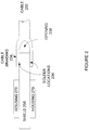
- Figure 1 illustrates a side view of a connector plug according to an embodiment of the present invention. This figure, as with the other included figures, is shown for illustrative purposes and does not limit either the possible embodiments of the present invention or the claims.
- Chip 140 may be an example circuit of many circuits that may generate the majority of heat in this plug. Again, embodiments of the present invention may employ several paths by which heat can be dissipated. In the first, heat can be removed from chip 140 directly to shield 150. Accordingly, a thermal conductor layer 160 may be used to provide a thermal path from chip 140 to shield 150. In a second path, chip 140 may attach to printed circuit board 120, thereby allowing heat to flow into printed circuit board 120. A solder area 180, which may be on the side, bottom, or top of printed circuit board 120, may be soldered to a portion of shield 150, thereby creating a low thermal resistance path from the printed circuit board to the shield for heat dissipation. From the shield, head can dissipate out through the cable. In a specific embodiment of the present invention, a side of the printed circuit board 120 is plated and soldered to the shield. The heat thus travels from the chip to the printed circuit board, then to the shield via the edge plating, then to the cable via cable braiding.
- the cable (not shown) also provides a path for heat to leave this plug.
- a braiding or other layer of the cable may be soldered or otherwise attached to shield 150. This may allow head to dissipate through the cable.
- a low thermal path which may include liquid, metal, or other material, may be included in the cable.
- Plug conductors 110 may also provide a heat path into a device receptacle.
- the device receptacle may be designed to provide low thermal resistance paths to further aid in the dissipation of heat in the plug.
- Figure 2 illustrates a side view of a connection between cable 230 and connector insert shield 250.
- Cable braiding 234 may be pulled away from cable 230 and soldered to shield 250 at solder locations 236.
- Conductors (not shown) in cable 230 may connect to circuitry inside shield 250.
- Housing 270 may surround portion of shield 250 to provide thermal insulation and the location for a user to grasp the connector insert.
- one or more openings 238 may form.
- shield 250 may have a width greater than its height. Some or all of cable braiding 234 may attach to shield 250 along the width of shield 250, thereby leaving opening 238 along the height (or side) of shield 250. Opening 238 may provide a path for electromagnetic interference to be emitted from the cable conductors (not shown). Accordingly, embodiments of the present invention may employ a cap or other structure over the opening 238. An example is shown in the following figure.
- Figure 3 illustrates a cap 339 that may be located over solder locations 236 between a cable braiding 234 and connector insert shield 250 consistent with embodiments of the present invention.
- Cap 339 may be formed of metal such as aluminum, stainless steel, or other material. During manufacturing, cap 339 may be placed over solder locations 236 and crimped to be held in place. Cap 339 may also be soldered to provide additional shielding and mechanical support.
- force may be applied to cap 439 in four directions, though in other embodiments of the present invention, force may be applied in other numbers of directions, such as two, three, or more than four directions.
- Figure 5 is a cross-section of a high-speed cable according to an embodiment of the present invention.
- This cable may include four twisted pairs 520 and four single wires 530. Twisted pairs 520 may be used to carry differential signals, multiple single ended signals, power, ground, bias, control, status, or other types of signal, power, status, or control lines.
- Single wires 530 may be used to convey single ended signals, one side of a differential signal, power, ground, bias control, status, or other types of signal, power, status, or control lines.
- cables consistent with embodiments of the present invention may include other numbers of twisted pairs and single wires.
- twisted-pairs 520 and single wires 530 surround a nylon core 560, which is used for mechanical support.
- nylon core 560 may be substituted by a wire, one or more fiber-optic lines, or other conductor or fiber. These connectors may be bound by shield tape 580.
- Shield braid 540 may surround the cable.
- Jacket 570 may surround shield braid 540 and provide mechanical support for the cable.
- aramid fibers 550 may be dispersed or grouped in shield braid 540.
- Shield braid 540 may be a conventional interwoven braiding, shield braid 540 may be formed of one or more counter-rotating spirals, or shield braiding 540 may be formed in other various ways.
- FIG. 6 is a more detailed view of twisted pair 520 according to an embodiment of the present invention.
- Twisted pairs 520 may include two conductors 610 surrounded by insulation layer 630.
- Spiral shield 620 may surround twisted-pair 520 and provides shielding against electromagnetic interference.
- Spiral shield 620 like shield braid 540, may be formed of braiding, one or more counter-rotating spirals, or other ways.
- Copper Mylar tape layer 670 may bind and provide mechanical support for spiral shield 620 and conductors 610.
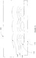
- Figure 7 illustrates a side view of a portion of the cable according to an embodiment of the present invention.
- This figure illustrates a cable surrounded by jacket 710.
- Jacket 710 has been cut away to reveal a first counter-rotating spiral 720 and a second counter-rotating spiral 730.
- the first of these spirals may have an angle approximately equal to phi 740.
- phi may be equal to 17 degrees. In other embodiments of the present invention, other angles may be used.
- the second of these may have approximately the same relative angle, shown here as negative phi 742 to indicate a different absolute direction.
- the wires in the counter-rotating spirals 720 and 730 may be easily peeled away, straightened, and soldered or otherwise electrically connected to locations in a connector plug.
- Utilizing counter-rotating spirals 720 and 730 may also improve flexibility of the cable. For example, when the cable is twisted in a first direction, counter-rotating spiral 720 may tighten while counter-rotating spiral 730 may loosen. The tightening of counter-rotating spiral 720 may protect the internal conductors. Similarly, when the cable is twisted in a second direction, counter-rotating spiral 730 may tighten while counter-rotating spiral 720 may loosen. The tightening of counter-rotating spirals 730 may protect the internal conductors.
- fibers may be employed by embodiments of the present invention. These fibers may be interspersed singly or in groups in one or more of the counter-rotating spirals 720 and 730. These fibers may be included for various reasons.
- aramid fibers may be included for additional strength. Again, aramid fibers may interfere with soldering of the counter-rotating spirals 720 and 730 to locations such as a shield of, or pads in, a connector insert. Accordingly, in various embodiments of the present invention, these fibers may be pulled away from the wires in the counter-rotating spirals 720 and 730 by static electricity, air movement, or other methods.
- the cable shown here may be made in a number of ways.
- the wires and twisted pairs are pulled from spools and then wrapped in various layers for mechanical support.
- the spools holding the wires and twisted pairs may be rotated during cable manufacturing. An example is shown in the following figure.
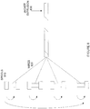
- Figure 8 illustrates the construction of a cable according to an embodiment of the present invention.
- a number of spools 810 may each hold one of the conductors 820.
- spools 810 may rotate, thereby individually twisting the wires.
- spools 810 may twist as a group, thus twisting the wires as a group.
- spools 810 may twist one-half turn, one turn, two turns, or other fractions or numbers of turns per length of cable.
- This combined twisting action may be referred to as planetary wire feeding, or as a planetary twist.
- other types of assembly may be used.
- a back twist, or no twist may be used.
- the various conductors may be bound together, for example using tape 825.
- a jacket may be extruded at 830, thus sealing the wires.
- Spools 810 may hold various types of conductors or groups of conductors. For example, they may hold single conductors, coaxial cables, twisted pairs or shielded twisted pairs, or other types of conductors or groups of conductors. In a specific embodiment of the present invention, the conductors on one or more spools 810 are grouped in pairs, referred to as twinaxial, or twinax cables.
- cables according to embodiments of the present invention may include a number of twisted pairs 520 and single wires 530, as shown in Figure 5 .
- the wires may connect to a printed circuit board in a connector insert, such as printed circuit board 120 in Figure 1 .
- twisted pairs 520 may emerge from an end of the cable in any orientation. As such, it may be difficult to solder the twisted pairs 520 to printed circuit board 120.
- embodiments of the present invention may employ a wire comb to align the twisted pairs 520 in order to simplify soldering to printed circuit board 120. Use of such a comb may improve the manufacturability of connector inserts according to embodiments of the present invention.
- An example of such a wire comb is shown in the following figure.
- Figure 9 illustrates a wire comb 910 that may be used to align twisted-pairs emerging from a cable according to an embodiment of the present invention.
- Wire comb 910 may include a plurality of non-circular openings 920 and circular openings 930. Twisted pairs 520 may be untwisted to the point where they fit in openings 920, then passed through openings 920. Single wires 530 may be passed through openings 930. In this way, connectors from a cable may be aligned as they emerge from wire comb 910. This allows the conductors to be soldered to printed circuit board 120, as shown in the following figure.
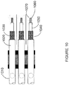
- Figure 10 illustrates a plurality of conductors 1010 that may be soldered to solder pads 1040 and 1070 on a printed circuit board, such as printed circuit board 120.
- connectors 1010 are covered by jacket 1020.
- Jacket 1020 may be removed thereby exposing braiding or shield layers 1030.
- Shield layers 1030 may be soldered to pads 1040.
- An internal isolation layer 1050 may be stripped away leaving connector terminals 1060, which may be soldered to pads 1070.
- solder shield layers 1030 to pads 1040 and connectors 1060 to pads 1070 may be desirable to be able to solder shield layers 1030 to pads 1040 and connectors 1060 to pads 1070 in a reliable manner. Accordingly, embodiments of the present invention may employ a shaped solder bar during the soldering process. An example is shown in the following figure.
- Figure 11 illustrates a method of soldering conductors to a printed circuit board according to an embodiment of the present invention.
- twisted-pair conductors 1120 are to be soldered to pads on a printed circuit board 1130.
- a shaped solder bar 1140 may be placed over connectors 1120.
- Hot bar 1110 may be heated, for example by passing a current from one end to another. Hot bar 1110 may be lowered such that solder bar 1140 is heated and flows, thereby soldering a shield layer of twisted pair is 1120 to pads on printed circuit board 1130.
- hot bar 1110 may include recesses 1150 such that solder bar 1140 is evenly heated. This configuration may provide a reliable solder connection between a shield braid of twisted-pair 1120 and a pad on printed circuit board 1130.
- Figure 12 illustrates a connector insert according to an embodiment of the present invention.
- This connector insert includes an insert portion 1210 to fit in a compliant connector receptacle.
- Housing 1220 may be included such that a user can manipulate the connector insert.
- Stress relief and cable 1230 are also included for illustrative purposes.
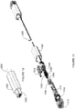
- Figure 13 illustrates an exploded view of a connector insert according to an embodiment of the present invention.
- Conductors of cable 1305 pass through wire comb 1140 as described above. These conductors attach to printed circuit board 1350.
- One or more circuits 1355 may be located on printed circuit board 1350.
- Contacts 1365 may be supported by structure 1360, and attach to printed circuit board 1350.
- Frame portions 1310 and 1312 may encapsulate printed circuit board 1350 and active circuitry 1355.
- Housing portions 1332 and 1320 may form a housing around the connector insert.
- a dust shield 1370 may be provided to protect the connector insert during transport and shipment.
Landscapes
- Engineering & Computer Science (AREA)
- Manufacturing & Machinery (AREA)
- Details Of Connecting Devices For Male And Female Coupling (AREA)
- Manufacturing Of Electrical Connectors (AREA)
- Multi-Conductor Connections (AREA)
- Connections Effected By Soldering, Adhesion, Or Permanent Deformation (AREA)
Applications Claiming Priority (5)
| Application Number | Priority Date | Filing Date | Title |
|---|---|---|---|
| US36043210P | 2010-06-30 | 2010-06-30 | |
| US36043610P | 2010-06-30 | 2010-06-30 | |
| US40805210P | 2010-10-29 | 2010-10-29 | |
| US13/033,562 US8327536B2 (en) | 2010-06-30 | 2011-02-23 | Method of manufacturing high-speed connector inserts and cables |
| EP11738523.7A EP2589119B1 (en) | 2010-06-30 | 2011-06-30 | Method of manufacturing a connector insert |
Related Parent Applications (2)
| Application Number | Title | Priority Date | Filing Date |
|---|---|---|---|
| EP11738523.7A Division EP2589119B1 (en) | 2010-06-30 | 2011-06-30 | Method of manufacturing a connector insert |
| EP11738523.7A Division-Into EP2589119B1 (en) | 2010-06-30 | 2011-06-30 | Method of manufacturing a connector insert |
Publications (1)
| Publication Number | Publication Date |
|---|---|
| EP3285340A1 true EP3285340A1 (en) | 2018-02-21 |
Family
ID=45398838
Family Applications (2)
| Application Number | Title | Priority Date | Filing Date |
|---|---|---|---|
| EP17194214.7A Withdrawn EP3285340A1 (en) | 2010-06-30 | 2011-06-30 | Connector insert and cable |
| EP11738523.7A Not-in-force EP2589119B1 (en) | 2010-06-30 | 2011-06-30 | Method of manufacturing a connector insert |
Family Applications After (1)
| Application Number | Title | Priority Date | Filing Date |
|---|---|---|---|
| EP11738523.7A Not-in-force EP2589119B1 (en) | 2010-06-30 | 2011-06-30 | Method of manufacturing a connector insert |
Country Status (7)
| Country | Link |
|---|---|
| US (3) | US8327536B2 (OSRAM) |
| EP (2) | EP3285340A1 (OSRAM) |
| JP (1) | JP5342700B2 (OSRAM) |
| KR (1) | KR101408474B1 (OSRAM) |
| CN (2) | CN202678638U (OSRAM) |
| BR (1) | BR112012031398A2 (OSRAM) |
| WO (1) | WO2012003347A1 (OSRAM) |
Families Citing this family (26)
| Publication number | Priority date | Publication date | Assignee | Title |
|---|---|---|---|---|
| US8976799B1 (en) | 2007-10-01 | 2015-03-10 | Apple Inc. | Converged computer I/O system and bridging mechanism for peer-to-peer communication |
| JP5283787B1 (ja) | 2010-06-30 | 2013-09-04 | アップル インコーポレイテッド | ケーブル内の配電 |
| US8327536B2 (en) | 2010-06-30 | 2012-12-11 | Apple Inc. | Method of manufacturing high-speed connector inserts and cables |
| US9112310B2 (en) | 2010-06-30 | 2015-08-18 | Apple Inc. | Spark gap for high-speed cable connectors |
| US20120226774A1 (en) | 2011-02-23 | 2012-09-06 | Apple Inc. | Display snooping |
| DK3685877T3 (da) | 2011-06-03 | 2023-10-02 | Fisher & Paykel Healthcare Ltd | Medicinske rør bestående af ledende filamenter og produktionsmetoder |
| US8870598B2 (en) * | 2012-11-30 | 2014-10-28 | Intel Corporation | Active electrical communication cable assembly |
| CN114082063B (zh) | 2012-12-04 | 2024-10-01 | 费雪派克医疗保健有限公司 | 医用管以及其制造方法 |
| JP2014160929A (ja) * | 2013-02-19 | 2014-09-04 | Sony Corp | 信号伝送ケーブル |
| WO2015060731A1 (en) | 2013-10-24 | 2015-04-30 | Fisher & Paykel Healthcare Limited | Delivery of respiratory gases |
| CN105814776B (zh) * | 2013-11-13 | 2018-12-21 | 包米勒公司 | 电动的驱动系统 |
| DE102013225794A1 (de) * | 2013-12-12 | 2015-06-18 | Leoni Kabel Holding Gmbh | Kontaktanbindung von geschirmten Datenleitungen an einer Platine sowie Verfahren zur Kontaktierung mehrerer geschirmter Datenleitungen an einer Platine |
| CN111265754B (zh) * | 2014-03-17 | 2023-06-06 | 费雪派克医疗保健有限公司 | 用于呼吸系统的医用管 |
| US9643272B2 (en) | 2014-08-14 | 2017-05-09 | Apple Inc. | Encapsulation process enabling hotbar soldering without direct PCB support |
| US20160062939A1 (en) * | 2014-08-31 | 2016-03-03 | Airborn, Inc. | Connector with in-circuit programming |
| US9934188B2 (en) | 2015-08-27 | 2018-04-03 | Kabushiki Kaisha Toshiba | Electronic device with connector for video signal interface |
| US10682498B2 (en) | 2015-09-24 | 2020-06-16 | Silicon Microstructures, Inc. | Light shields for catheter sensors |
| US10641672B2 (en) | 2015-09-24 | 2020-05-05 | Silicon Microstructures, Inc. | Manufacturing catheter sensors |
| US10275000B2 (en) * | 2016-09-06 | 2019-04-30 | Google Llc | Thermally conductive cables |
| CN106413371A (zh) * | 2016-11-30 | 2017-02-15 | 依偎科技(南昌)有限公司 | 移动终端及其制备方法 |
| JP2018142400A (ja) * | 2017-02-24 | 2018-09-13 | 日立金属株式会社 | ケーブル実装用基板、ケーブル付き基板、及びケーブル実装用基板へのケーブルの接続方法 |
| CN108493672A (zh) * | 2018-05-03 | 2018-09-04 | 江苏和飞航天电子有限公司 | 一种新型高防水连接器及其生产工艺 |
| TWI649927B (zh) * | 2018-06-22 | 2019-02-01 | 華碩電腦股份有限公司 | 信號傳輸線纜 |
| CN109301600A (zh) * | 2018-09-25 | 2019-02-01 | 昆山柯斯美光电有限公司 | 全屏蔽的光纤hdmi连接器及连接线 |
| US10930411B2 (en) * | 2018-10-11 | 2021-02-23 | International Business Machines Corporation | Hybrid cable assembly having shielded and unshielded portions |
| US11121489B2 (en) | 2019-08-20 | 2021-09-14 | Seagate Technology Llc | Electrical connector with flexible circuit and stiffener |
Citations (5)
| Publication number | Priority date | Publication date | Assignee | Title |
|---|---|---|---|---|
| US5103067A (en) * | 1991-02-19 | 1992-04-07 | Champlain Cable Corporation | Shielded wire and cable |
| US20050237068A1 (en) * | 2004-03-31 | 2005-10-27 | Omron Corporation | Sensor cable having easily changeable entire length and allowing accurate and high speed signal transmission even when entire length is made longer, and amplifier-separated type sensor with the cable |
| WO2006102606A2 (en) * | 2005-03-23 | 2006-09-28 | Pulse Engineering, Inc. | Power-enabled connector assembly and method of manufacturing |
| WO2009039287A2 (en) * | 2007-09-21 | 2009-03-26 | 3M Innovative Properties Company | Multicore cable connector |
| EP2109352A2 (en) * | 2008-04-11 | 2009-10-14 | Hosiden Corporation | Shield case and circuit board assembly |
Family Cites Families (139)
| Publication number | Priority date | Publication date | Assignee | Title |
|---|---|---|---|---|
| US3581143A (en) | 1969-01-16 | 1971-05-25 | Sprague Electric Co | Ontracking wire spark gap component |
| JPS5764083U (OSRAM) * | 1980-10-02 | 1982-04-16 | ||
| US4628151A (en) | 1985-12-30 | 1986-12-09 | Cardas George F | Multi-strand conductor cable having its strands sized according to the golden section |
| JPH0626332B2 (ja) | 1990-10-29 | 1994-04-06 | 岩崎通信機株式会社 | デジタル通信路の同期装置 |
| JPH0541255A (ja) | 1991-08-06 | 1993-02-19 | Fujitsu Ltd | ケーブル接続識別装置 |
| US5313465A (en) | 1992-05-13 | 1994-05-17 | Digital Equipment Corporation | Method of merging networks across a common backbone network |
| JPH08265600A (ja) | 1995-03-20 | 1996-10-11 | Fujitsu General Ltd | ビデオカメラのフィールド同期装置 |
| US5711686A (en) * | 1996-03-01 | 1998-01-27 | Molex Incorporated | System for terminating the shield of a high speed cable |
| US6169251B1 (en) | 1997-03-31 | 2001-01-02 | The Whitaker Corporation | Quad cable |
| US6029137A (en) | 1997-05-29 | 2000-02-22 | Pitney Bowes Inc. | Updating domains in a postage evidencing system |
| JPH11273790A (ja) | 1998-03-24 | 1999-10-08 | Kokusai Electric Co Ltd | コネクタケーブル及びその識別方法 |
| US6017245A (en) * | 1998-08-19 | 2000-01-25 | Amphenol Corporation | Stamped backshell assembly with integral front shield and rear cable clamp |
| GB9821511D0 (en) * | 1998-10-03 | 1998-11-25 | Smiths Industries Plc | Electrical connection |
| US6495763B1 (en) | 1999-06-09 | 2002-12-17 | Keith Louis Eichmann | Specific cable ratio for high fidelity audio cables |
| DE19929337C2 (de) | 1999-06-26 | 2002-04-25 | Alcatel Sa | Verfahren zum Generieren eines Taktes für den Rückkanal eines bidirektionalen Punkt-zu-Mehrpunkt Netzwerkes |
| JP2001109697A (ja) | 1999-10-07 | 2001-04-20 | Victor Co Of Japan Ltd | マルチインターフェース装置およびbios処理方法 |
| US6792474B1 (en) | 2000-03-27 | 2004-09-14 | Cisco Technology, Inc. | Apparatus and methods for allocating addresses in a network |
| US6934763B2 (en) | 2000-04-04 | 2005-08-23 | Fujitsu Limited | Communication data relay system and method of controlling connectability between domains |
| US7032031B2 (en) | 2000-06-23 | 2006-04-18 | Cloudshield Technologies, Inc. | Edge adapter apparatus and method |
| JP3645170B2 (ja) * | 2000-10-27 | 2005-05-11 | タイコエレクトロニクスアンプ株式会社 | 電気ケーブル端部構造および電気ケーブル端部処理方法 |
| US7006535B2 (en) | 2001-01-12 | 2006-02-28 | Broadcom Corporation | Method and system for providing time offset to minislot clock and count in headend devices |
| JP2002318647A (ja) | 2001-04-19 | 2002-10-31 | Mitsubishi Electric Corp | 検出装置及びその検出方法 |
| US20060023386A1 (en) | 2001-05-16 | 2006-02-02 | John Mezzalingua Associates, Inc. | Spark gap device |
| US7197549B1 (en) | 2001-06-04 | 2007-03-27 | Cisco Technology, Inc. | On-demand address pools |
| JP3678179B2 (ja) | 2001-07-25 | 2005-08-03 | 日立電線株式会社 | 2重横巻2心平行極細同軸ケーブル |
| US20030030720A1 (en) | 2001-08-10 | 2003-02-13 | General Instrument Corporation | Wireless video display apparatus and associated method |
| US7860205B1 (en) | 2001-09-18 | 2010-12-28 | Ciena Corporation | Clock synchronization using a weighted least squares error filtering technique |
| JP2003189263A (ja) | 2001-12-20 | 2003-07-04 | Shibasoku:Kk | フォーマット変換装置 |
| US7099354B2 (en) | 2002-01-24 | 2006-08-29 | Radioframe Networks, Inc. | Method and apparatus for frequency and timing distribution through a packet-based network |
| US7162731B2 (en) | 2002-02-07 | 2007-01-09 | Advent Networks, Inc. | Radio frequency characterization of cable plant and corresponding calibration of communication equipment communicating via the cable plant |
| CN100392637C (zh) | 2002-03-21 | 2008-06-04 | 美国联合包裹服务公司 | 远程信息处理编程逻辑控制单元和使用方法 |
| US6653813B2 (en) | 2002-03-21 | 2003-11-25 | Thomson Licensing, S.A. | Apparatus and method for the power management of operatively connected modular devices |
| US6625169B1 (en) | 2002-06-14 | 2003-09-23 | Telesys Technologies, Inc. | Integrated communication systems for exchanging data and information between networks |
| US7561855B2 (en) | 2002-06-25 | 2009-07-14 | Finisar Corporation | Transceiver module and integrated circuit with clock and data recovery clock diplexing |
| JP4221968B2 (ja) | 2002-07-31 | 2009-02-12 | 住友電気工業株式会社 | 2芯平行シールドケーブル及び配線部品並びに情報機器 |
| JP2004095518A (ja) * | 2002-09-02 | 2004-03-25 | Shintake Sangyo Kk | セミリジットケーブル付きl型プラグおよびその製造方法 |
| JP4221238B2 (ja) | 2002-09-26 | 2009-02-12 | エルピーダメモリ株式会社 | メモリモジュール |
| JP2004126885A (ja) | 2002-10-01 | 2004-04-22 | Sony Corp | 非接触ケーブルおよびその動作方法 |
| US20040080544A1 (en) | 2002-10-29 | 2004-04-29 | Stripling Jeffrey Ricks | System and method for providing network access to devices using numeric input |
| JP2004193090A (ja) * | 2002-12-09 | 2004-07-08 | Shintake Sangyo Kk | 同軸ケーブル用プラグ |
| US6869308B2 (en) | 2002-12-11 | 2005-03-22 | Hon Hai Precision Ind. Co., Ltd. | Cable connector having cross-talk suppressing feature and method for making the connector |
| US7188209B2 (en) | 2003-04-18 | 2007-03-06 | Nextio, Inc. | Apparatus and method for sharing I/O endpoints within a load store fabric by encapsulation of domain information in transaction layer packets |
| US7219183B2 (en) | 2003-01-21 | 2007-05-15 | Nextio, Inc. | Switching apparatus and method for providing shared I/O within a load-store fabric |
| US7174413B2 (en) | 2003-01-21 | 2007-02-06 | Nextio Inc. | Switching apparatus and method for providing shared I/O within a load-store fabric |
| US6969270B2 (en) | 2003-06-26 | 2005-11-29 | Intel Corporation | Integrated socket and cable connector |
| US20050044236A1 (en) | 2003-08-06 | 2005-02-24 | David Stafford | Method and apparatus for transmitting keyboard/video/mouse data to and from digital video appliances |
| US7096308B2 (en) | 2003-08-29 | 2006-08-22 | Texas Instruments Incorporated | LPC transaction bridging across a PCI—express docking connection |
| US7062590B2 (en) | 2003-08-29 | 2006-06-13 | Lsi Logic Corporation | Methods and structure for PCI bus broadcast using device ID messaging |
| US7411971B2 (en) | 2003-09-09 | 2008-08-12 | Avaya Inc. | Systems and methods for the schedule alignment of packet flow |
| US7269673B2 (en) | 2004-02-18 | 2007-09-11 | Silicon Image, Inc. | Cable with circuitry for asserting stored cable data or other information to an external device or user |
| JP4387832B2 (ja) * | 2004-02-26 | 2009-12-24 | 富士通コンポーネント株式会社 | 平衡伝送用ケーブルコネクタ |
| JP2005309744A (ja) | 2004-04-21 | 2005-11-04 | Yokohama Tlo Co Ltd | センサー制御システム及び汎用入出力制御装置 |
| US8374175B2 (en) | 2004-04-27 | 2013-02-12 | Hewlett-Packard Development Company, L.P. | System and method for remote direct memory access over a network switch fabric |
| US20050262269A1 (en) | 2004-05-20 | 2005-11-24 | Pike Jimmy D | System and method for information handling system PCI express advanced switching |
| US7033219B2 (en) * | 2004-06-10 | 2006-04-25 | Commscope Solutions Properties, Llc | Modular plug assemblies, terminated cable assemblies and methods for forming the same |
| US7447922B1 (en) | 2004-06-23 | 2008-11-04 | Cypress Semiconductor Corp. | Supplying power from peripheral to host via USB |
| US7161784B2 (en) | 2004-06-30 | 2007-01-09 | Research In Motion Limited | Spark gap apparatus and method for electrostatic discharge protection |
| US6998538B1 (en) | 2004-07-30 | 2006-02-14 | Ulectra Corporation | Integrated power and data insulated electrical cable having a metallic outer jacket |
| US7466712B2 (en) | 2004-07-30 | 2008-12-16 | Brocade Communications Systems, Inc. | System and method for providing proxy and translation domains in a fibre channel router |
| JP2006048594A (ja) | 2004-08-09 | 2006-02-16 | Canon Inc | Usbデバイス装置 |
| US7366182B2 (en) | 2004-08-13 | 2008-04-29 | Qualcomm Incorporated | Methods and apparatus for efficient VPN server interface, address allocation, and signaling with a local addressing domain |
| US20060083518A1 (en) | 2004-10-14 | 2006-04-20 | Myunghee Lee | Fiber optic connection for digital displays |
| US20060092928A1 (en) | 2004-10-15 | 2006-05-04 | Dell Products L.P. | System and method for providing a shareable input/output device in a PCI express environment |
| US8285907B2 (en) | 2004-12-10 | 2012-10-09 | Intel Corporation | Packet processing in switched fabric networks |
| US20060200600A1 (en) | 2005-01-12 | 2006-09-07 | Cubix Corporation | Optical bus extension device |
| US20060168387A1 (en) | 2005-01-26 | 2006-07-27 | Phison Electronics Corp. | [crad reader with pci express] |
| TW200627322A (en) | 2005-01-28 | 2006-08-01 | Chien-Chuan Chu | Apparatus contains 2-wire power line and server/client circuits with each end, substituting for power transmitting line of traffic lights |
| US7480303B1 (en) | 2005-05-16 | 2009-01-20 | Pericom Semiconductor Corp. | Pseudo-ethernet switch without ethernet media-access-controllers (MAC's) that copies ethernet context registers between PCI-express ports |
| US7970958B2 (en) | 2005-06-20 | 2011-06-28 | Micron Technology, Inc. | Peripheral interface alert message for downstream device |
| US7437643B2 (en) | 2005-06-21 | 2008-10-14 | Intel Corporation | Automated BIST execution scheme for a link |
| KR101197280B1 (ko) | 2005-07-15 | 2012-11-05 | 삼성전자주식회사 | 타임 스탬프를 이용한 타임 동기 방법 및 장치 |
| EP1934990B1 (en) | 2005-09-19 | 2012-11-07 | Telefonix, Inc. | Flexible and lightweight seat-to-seat cabin cable system and method of manufacturing same |
| JP2007086876A (ja) | 2005-09-20 | 2007-04-05 | Ricoh Co Ltd | データ伝送路搭載acアダプタ |
| JP4058067B2 (ja) | 2005-09-28 | 2008-03-05 | 株式会社日立コミュニケーションテクノロジー | 通信システム |
| JP4673191B2 (ja) | 2005-11-15 | 2011-04-20 | 富士通コンポーネント株式会社 | ケーブルコネクタ |
| US7707465B2 (en) | 2006-01-26 | 2010-04-27 | International Business Machines Corporation | Routing of shared I/O fabric error messages in a multi-host environment to a master control root node |
| US7743197B2 (en) | 2006-05-11 | 2010-06-22 | Emulex Design & Manufacturing Corporation | System and method for virtualizing PCIe devices |
| US7660917B2 (en) | 2006-03-02 | 2010-02-09 | International Business Machines Corporation | System and method of implementing multiple internal virtual channels based on a single external virtual channel |
| WO2007099507A2 (en) | 2006-03-02 | 2007-09-07 | International Business Machines Corporation | Operating a network monitoring entity |
| JP2007251779A (ja) | 2006-03-17 | 2007-09-27 | Casio Comput Co Ltd | デジタルカメラシステムおよびデジタルカメラ |
| US8261100B2 (en) | 2006-08-30 | 2012-09-04 | Green Plug, Inc. | Power adapter capable of communicating digitally with electronic devices using packet-based protocol |
| US7865633B2 (en) | 2006-08-31 | 2011-01-04 | Cisco Technology, Inc. | Multiple context single logic virtual host channel adapter |
| US7397283B2 (en) | 2006-09-29 | 2008-07-08 | Parade Technologies, Ltd. | Digital A/V transmission PHY signaling format conversion, multiplexing, and de-multiplexing |
| US7809870B2 (en) | 2006-10-17 | 2010-10-05 | Broadcom Corporation | Method and system for interlocking data integrity for network adapters |
| US7587575B2 (en) | 2006-10-17 | 2009-09-08 | International Business Machines Corporation | Communicating with a memory registration enabled adapter using cached address translations |
| US7255602B1 (en) | 2006-11-02 | 2007-08-14 | Hamilton Sundstrand Corporation | Shielding for electrical cable assemblies |
| TWI513264B (zh) | 2006-11-07 | 2015-12-11 | Sony Corp | Reception apparatus, reception method |
| US7830882B2 (en) | 2006-11-17 | 2010-11-09 | Intel Corporation | Switch scaling for virtualized network interface controllers |
| US7602192B2 (en) | 2006-11-30 | 2009-10-13 | Electro Scientific Industries, Inc. | Passive station power distribution for cable reduction |
| US7529860B2 (en) | 2006-12-19 | 2009-05-05 | International Business Machines Corporation | System and method for configuring an endpoint based on specified valid combinations of functions |
| US8051217B2 (en) | 2007-01-12 | 2011-11-01 | Dell Products L.P. | System and method for providing PCIe over displayport |
| US20080256445A1 (en) | 2007-02-05 | 2008-10-16 | Olch Ronald H | System and method for automated aids for activities of daily living |
| US8948173B2 (en) | 2007-02-14 | 2015-02-03 | Marvell International Ltd. | Control protocol encapsulation |
| US7562176B2 (en) | 2007-02-28 | 2009-07-14 | Lsi Corporation | Apparatus and methods for clustering multiple independent PCI express hierarchies |
| US7689755B2 (en) | 2007-03-07 | 2010-03-30 | Intel Corporation | Apparatus and method for sharing devices between multiple execution domains of a hardware platform |
| JP2008252310A (ja) | 2007-03-29 | 2008-10-16 | Fujitsu Component Ltd | 中継装置及び中継システム |
| US20080250175A1 (en) | 2007-04-03 | 2008-10-09 | Vizionware, Inc. | Cable assembly having an adaptive two-wire bus |
| US7734859B2 (en) | 2007-04-20 | 2010-06-08 | Nuon, Inc | Virtualization of a host computer's native I/O system architecture via the internet and LANs |
| US20080266730A1 (en) | 2007-04-25 | 2008-10-30 | Karsten Viborg | Spark Gaps for ESD Protection |
| US7869431B2 (en) | 2007-05-10 | 2011-01-11 | Dell Products L.P. | System and method for communication of uncompressed visual information through a network |
| US7901955B2 (en) | 2007-06-25 | 2011-03-08 | Spansion Llc | Method of constructing a stacked-die semiconductor structure |
| US7917682B2 (en) | 2007-06-27 | 2011-03-29 | Emulex Design & Manufacturing Corporation | Multi-protocol controller that supports PCIe, SAS and enhanced Ethernet |
| US20090003335A1 (en) | 2007-06-29 | 2009-01-01 | International Business Machines Corporation | Device, System and Method of Fragmentation of PCI Express Packets |
| US7876759B2 (en) | 2007-07-11 | 2011-01-25 | Hewlett-Packard Development Company, L.P. | Quality of service with control flow packet filtering |
| US20090022176A1 (en) | 2007-07-21 | 2009-01-22 | Nguyen James T | System and method for converting communication interfaces and protocols |
| US8151005B2 (en) | 2007-08-04 | 2012-04-03 | Broadcom Corporation | System and method for adjusting a level of compression for computing clients |
| US7422471B1 (en) * | 2007-08-14 | 2008-09-09 | Hon Hai Precision Ind. Co., Ltd. | Electrical connector with heat sink function |
| DE202008001256U1 (de) | 2007-08-20 | 2008-04-30 | Klees, Ernst | Identifizerbares Kabel |
| US20090063747A1 (en) | 2007-08-28 | 2009-03-05 | Rohati Systems, Inc. | Application network appliances with inter-module communications using a universal serial bus |
| US8316377B2 (en) | 2007-09-06 | 2012-11-20 | Hewlett-Packard Development Company, L.P. | Sharing legacy devices in a multi-host environment |
| US8976799B1 (en) | 2007-10-01 | 2015-03-10 | Apple Inc. | Converged computer I/O system and bridging mechanism for peer-to-peer communication |
| CN101334762B (zh) | 2007-10-12 | 2011-05-18 | 硅谷数模半导体(北京)有限公司 | 用在计算机中的数据传输系统 |
| US7841910B2 (en) | 2007-11-06 | 2010-11-30 | Apple Inc. | Mini displayport |
| JP2009123561A (ja) | 2007-11-15 | 2009-06-04 | Sumitomo Electric Ind Ltd | 光dviケーブル |
| WO2009077929A1 (en) | 2007-12-14 | 2009-06-25 | Koninklijke Philips Electronics N.V. | 3d mode selection mechanism for video playback |
| US8723756B2 (en) | 2008-01-15 | 2014-05-13 | Synaptics Incorporated | System having capability for daisy-chained serial distribution of video display data |
| US8169241B2 (en) | 2008-01-15 | 2012-05-01 | Atmel Rousset S.A.S. | Proportional phase comparator and method for phase-aligning digital signals |
| US8094684B2 (en) | 2008-05-09 | 2012-01-10 | Parade Technologies, Ltd. | Link training scheme for displayport source repeaters |
| US7728223B2 (en) | 2008-06-05 | 2010-06-01 | Sony Corporation | Flat cable for mounted display devices |
| US8228689B2 (en) | 2008-07-17 | 2012-07-24 | Lsi Corporation | Active components on an internal cable to improve signal integrity |
| US20100046590A1 (en) | 2008-08-19 | 2010-02-25 | International Business Machines Corporation | Extending transmission distance in a high-speed serial network |
| JP5277827B2 (ja) | 2008-09-22 | 2013-08-28 | 東京エレクトロン株式会社 | プローブ装置 |
| US8176214B2 (en) | 2008-10-31 | 2012-05-08 | Silicon Image, Inc. | Transmission of alternative content over standard device connectors |
| WO2010092812A1 (ja) | 2009-02-16 | 2010-08-19 | 株式会社フジクラ | 伝送ケーブル |
| US20110256756A1 (en) * | 2009-07-15 | 2011-10-20 | Luxi Electronics Corp. | Diiva, displayport, dvi, usb, and hdmi diy field termination products |
| US8400782B2 (en) | 2009-07-24 | 2013-03-19 | Ibiden Co., Ltd. | Wiring board and method for manufacturing the same |
| US20110167187A1 (en) | 2010-01-06 | 2011-07-07 | Apple Inc. | Connectors in a portable device |
| US8267718B2 (en) * | 2010-04-07 | 2012-09-18 | Panduit Corp. | High data rate electrical connector and cable assembly |
| US20120103651A1 (en) | 2010-10-29 | 2012-05-03 | Apple Inc. | High-speed cable configurations |
| US8327536B2 (en) | 2010-06-30 | 2012-12-11 | Apple Inc. | Method of manufacturing high-speed connector inserts and cables |
| US9112310B2 (en) | 2010-06-30 | 2015-08-18 | Apple Inc. | Spark gap for high-speed cable connectors |
| JP5283787B1 (ja) | 2010-06-30 | 2013-09-04 | アップル インコーポレイテッド | ケーブル内の配電 |
| US8380912B2 (en) | 2010-09-24 | 2013-02-19 | Nxp B.V. | Transparent repeater device for handling displayport configuration data (DPCD) |
| US20120104543A1 (en) | 2010-10-29 | 2012-05-03 | Apple Inc. | High-speed memory sockets and interposers |
| US8842081B2 (en) | 2011-01-13 | 2014-09-23 | Synaptics Incorporated | Integrated display and touch system with displayport/embedded displayport interface |
| US20120226774A1 (en) | 2011-02-23 | 2012-09-06 | Apple Inc. | Display snooping |
| CN103650256B (zh) * | 2011-07-07 | 2017-04-12 | 莫列斯公司 | 用于端接一多导线线缆的托架以及线缆连接器 |
| US8801461B2 (en) * | 2012-02-09 | 2014-08-12 | Apple Inc. | Stepped termination block |
| US8696378B2 (en) * | 2012-02-24 | 2014-04-15 | Tyco Electronics Corporation | Electrical connector assembly and printed circuit board configured to electrically couple to a communication cable |
-
2011
- 2011-02-23 US US13/033,562 patent/US8327536B2/en not_active Expired - Fee Related
- 2011-06-30 BR BR112012031398A patent/BR112012031398A2/pt active Search and Examination
- 2011-06-30 EP EP17194214.7A patent/EP3285340A1/en not_active Withdrawn
- 2011-06-30 WO PCT/US2011/042634 patent/WO2012003347A1/en not_active Ceased
- 2011-06-30 JP JP2012547345A patent/JP5342700B2/ja not_active Expired - Fee Related
- 2011-06-30 KR KR1020127032488A patent/KR101408474B1/ko active Active
- 2011-06-30 CN CN2011202351644U patent/CN202678638U/zh not_active Expired - Fee Related
- 2011-06-30 EP EP11738523.7A patent/EP2589119B1/en not_active Not-in-force
- 2011-06-30 CN CN201110189137.2A patent/CN102332663B/zh active Active
-
2012
- 2012-02-24 US US13/404,949 patent/US9385478B2/en active Active
-
2016
- 2016-07-04 US US15/201,580 patent/US10199778B2/en active Active
Patent Citations (5)
| Publication number | Priority date | Publication date | Assignee | Title |
|---|---|---|---|---|
| US5103067A (en) * | 1991-02-19 | 1992-04-07 | Champlain Cable Corporation | Shielded wire and cable |
| US20050237068A1 (en) * | 2004-03-31 | 2005-10-27 | Omron Corporation | Sensor cable having easily changeable entire length and allowing accurate and high speed signal transmission even when entire length is made longer, and amplifier-separated type sensor with the cable |
| WO2006102606A2 (en) * | 2005-03-23 | 2006-09-28 | Pulse Engineering, Inc. | Power-enabled connector assembly and method of manufacturing |
| WO2009039287A2 (en) * | 2007-09-21 | 2009-03-26 | 3M Innovative Properties Company | Multicore cable connector |
| EP2109352A2 (en) * | 2008-04-11 | 2009-10-14 | Hosiden Corporation | Shield case and circuit board assembly |
Also Published As
| Publication number | Publication date |
|---|---|
| CN102332663A (zh) | 2012-01-25 |
| US9385478B2 (en) | 2016-07-05 |
| JP5342700B2 (ja) | 2013-11-13 |
| EP2589119A1 (en) | 2013-05-08 |
| WO2012003347A1 (en) | 2012-01-05 |
| JP2013516047A (ja) | 2013-05-09 |
| US10199778B2 (en) | 2019-02-05 |
| KR101408474B1 (ko) | 2014-06-17 |
| HK1166665A1 (en) | 2012-11-02 |
| US20170133798A1 (en) | 2017-05-11 |
| US20120000703A1 (en) | 2012-01-05 |
| CN102332663B (zh) | 2015-01-07 |
| KR20130018325A (ko) | 2013-02-20 |
| BR112012031398A2 (pt) | 2016-11-08 |
| US8327536B2 (en) | 2012-12-11 |
| CN202678638U (zh) | 2013-01-16 |
| US20120152613A1 (en) | 2012-06-21 |
| EP2589119B1 (en) | 2017-11-08 |
Similar Documents
| Publication | Publication Date | Title |
|---|---|---|
| US8327536B2 (en) | Method of manufacturing high-speed connector inserts and cables | |
| US8801461B2 (en) | Stepped termination block | |
| TWI627804B (zh) | Cable assembly and circuit board assembly | |
| US6585528B1 (en) | Wire spacer for high speed cable termination | |
| US20090166082A1 (en) | Anti-electromagnetic-interference signal transmission flat cable | |
| TWI746561B (zh) | 高效能纜線終端 | |
| CN203465966U (zh) | 多芯线缆组件 | |
| CN107887714A (zh) | 电缆连接用结构和电缆用连接器 | |
| US20090104819A1 (en) | High bandwidth connector | |
| CN110034443A (zh) | 一种hdmi电缆 | |
| TW202304080A (zh) | 高效能纜線終端 | |
| CN102856752A (zh) | 具有中继器单元的数据传输电缆和包括该电缆的电缆组件 | |
| CN102856753A (zh) | 用于数据线的连接元件 | |
| US11581722B2 (en) | Electrical cable splice | |
| TWI535130B (zh) | 高速連接器嵌入物及纜線 | |
| JP6320629B2 (ja) | 多極コネクタおよびコネクタ装置 | |
| HK1166665B (en) | High-speed connector inserts and cables | |
| KR102123637B1 (ko) | 멀티채널 커넥터 | |
| CN107732578B (zh) | 线缆连接器 | |
| EP4170833A1 (en) | Shield termination system that eliminates cable shield drain-wires | |
| JP2018523292A (ja) | 高速プラグ |
Legal Events
| Date | Code | Title | Description |
|---|---|---|---|
| PUAI | Public reference made under article 153(3) epc to a published international application that has entered the european phase |
Free format text: ORIGINAL CODE: 0009012 |
|
| STAA | Information on the status of an ep patent application or granted ep patent |
Free format text: STATUS: REQUEST FOR EXAMINATION WAS MADE |
|
| 17P | Request for examination filed |
Effective date: 20170929 |
|
| AC | Divisional application: reference to earlier application |
Ref document number: 2589119 Country of ref document: EP Kind code of ref document: P |
|
| AK | Designated contracting states |
Kind code of ref document: A1 Designated state(s): AL AT BE BG CH CY CZ DE DK EE ES FI FR GB GR HR HU IE IS IT LI LT LU LV MC MK MT NL NO PL PT RO RS SE SI SK SM TR |
|
| RAP1 | Party data changed (applicant data changed or rights of an application transferred) |
Owner name: APPLE INC. |
|
| STAA | Information on the status of an ep patent application or granted ep patent |
Free format text: STATUS: EXAMINATION IS IN PROGRESS |
|
| 17Q | First examination report despatched |
Effective date: 20190531 |
|
| STAA | Information on the status of an ep patent application or granted ep patent |
Free format text: STATUS: THE APPLICATION IS DEEMED TO BE WITHDRAWN |
|
| 18D | Application deemed to be withdrawn |
Effective date: 20191011 |