EP3285074B1 - Mikrodosiereinrichtung und automatisches mikrodosierverfahren - Google Patents
Mikrodosiereinrichtung und automatisches mikrodosierverfahren Download PDFInfo
- Publication number
- EP3285074B1 EP3285074B1 EP17185313.8A EP17185313A EP3285074B1 EP 3285074 B1 EP3285074 B1 EP 3285074B1 EP 17185313 A EP17185313 A EP 17185313A EP 3285074 B1 EP3285074 B1 EP 3285074B1
- Authority
- EP
- European Patent Office
- Prior art keywords
- light
- intensity
- liquid
- dosing
- light beam
- Prior art date
- Legal status (The legal status is an assumption and is not a legal conclusion. Google has not performed a legal analysis and makes no representation as to the accuracy of the status listed.)
- Active
Links
Images


Classifications
-
- B—PERFORMING OPERATIONS; TRANSPORTING
- B01—PHYSICAL OR CHEMICAL PROCESSES OR APPARATUS IN GENERAL
- B01L—CHEMICAL OR PHYSICAL LABORATORY APPARATUS FOR GENERAL USE
- B01L3/00—Containers or dishes for laboratory use, e.g. laboratory glassware; Droppers
- B01L3/02—Burettes; Pipettes
- B01L3/0241—Drop counters; Drop formers
-
- G—PHYSICS
- G01—MEASURING; TESTING
- G01N—INVESTIGATING OR ANALYSING MATERIALS BY DETERMINING THEIR CHEMICAL OR PHYSICAL PROPERTIES
- G01N35/00—Automatic analysis not limited to methods or materials provided for in any single one of groups G01N1/00 - G01N33/00; Handling materials therefor
- G01N35/10—Devices for transferring samples or any liquids to, in, or from, the analysis apparatus, e.g. suction devices, injection devices
- G01N35/1009—Characterised by arrangements for controlling the aspiration or dispense of liquids
- G01N35/1016—Control of the volume dispensed or introduced
-
- G—PHYSICS
- G01—MEASURING; TESTING
- G01N—INVESTIGATING OR ANALYSING MATERIALS BY DETERMINING THEIR CHEMICAL OR PHYSICAL PROPERTIES
- G01N35/00—Automatic analysis not limited to methods or materials provided for in any single one of groups G01N1/00 - G01N33/00; Handling materials therefor
- G01N35/02—Automatic analysis not limited to methods or materials provided for in any single one of groups G01N1/00 - G01N33/00; Handling materials therefor using a plurality of sample containers moved by a conveyor system past one or more treatment or analysis stations
- G01N35/04—Details of the conveyor system
-
- B—PERFORMING OPERATIONS; TRANSPORTING
- B01—PHYSICAL OR CHEMICAL PROCESSES OR APPARATUS IN GENERAL
- B01L—CHEMICAL OR PHYSICAL LABORATORY APPARATUS FOR GENERAL USE
- B01L3/00—Containers or dishes for laboratory use, e.g. laboratory glassware; Droppers
-
- B—PERFORMING OPERATIONS; TRANSPORTING
- B01—PHYSICAL OR CHEMICAL PROCESSES OR APPARATUS IN GENERAL
- B01L—CHEMICAL OR PHYSICAL LABORATORY APPARATUS FOR GENERAL USE
- B01L3/00—Containers or dishes for laboratory use, e.g. laboratory glassware; Droppers
- B01L3/02—Burettes; Pipettes
-
- B—PERFORMING OPERATIONS; TRANSPORTING
- B01—PHYSICAL OR CHEMICAL PROCESSES OR APPARATUS IN GENERAL
- B01L—CHEMICAL OR PHYSICAL LABORATORY APPARATUS FOR GENERAL USE
- B01L3/00—Containers or dishes for laboratory use, e.g. laboratory glassware; Droppers
- B01L3/50—Containers for the purpose of retaining a material to be analysed, e.g. test tubes
- B01L3/502—Containers for the purpose of retaining a material to be analysed, e.g. test tubes with fluid transport, e.g. in multi-compartment structures
- B01L3/5027—Containers for the purpose of retaining a material to be analysed, e.g. test tubes with fluid transport, e.g. in multi-compartment structures by integrated microfluidic structures, i.e. dimensions of channels and chambers are such that surface tension forces are important, e.g. lab-on-a-chip
-
- B—PERFORMING OPERATIONS; TRANSPORTING
- B41—PRINTING; LINING MACHINES; TYPEWRITERS; STAMPS
- B41J—TYPEWRITERS; SELECTIVE PRINTING MECHANISMS, i.e. MECHANISMS PRINTING OTHERWISE THAN FROM A FORME; CORRECTION OF TYPOGRAPHICAL ERRORS
- B41J2/00—Typewriters or selective printing mechanisms characterised by the printing or marking process for which they are designed
- B41J2/005—Typewriters or selective printing mechanisms characterised by the printing or marking process for which they are designed characterised by bringing liquid or particles selectively into contact with a printing material
- B41J2/01—Ink jet
- B41J2/135—Nozzles
- B41J2/165—Prevention or detection of nozzle clogging, e.g. cleaning, capping or moistening for nozzles
- B41J2/16579—Detection means therefor, e.g. for nozzle clogging
-
- B—PERFORMING OPERATIONS; TRANSPORTING
- B41—PRINTING; LINING MACHINES; TYPEWRITERS; STAMPS
- B41J—TYPEWRITERS; SELECTIVE PRINTING MECHANISMS, i.e. MECHANISMS PRINTING OTHERWISE THAN FROM A FORME; CORRECTION OF TYPOGRAPHICAL ERRORS
- B41J2/00—Typewriters or selective printing mechanisms characterised by the printing or marking process for which they are designed
- B41J2/005—Typewriters or selective printing mechanisms characterised by the printing or marking process for which they are designed characterised by bringing liquid or particles selectively into contact with a printing material
- B41J2/01—Ink jet
- B41J2/21—Ink jet for multi-colour printing
- B41J2/2132—Print quality control characterised by dot disposition, e.g. for reducing white stripes or banding
- B41J2/2142—Detection of malfunctioning nozzles
-
- C—CHEMISTRY; METALLURGY
- C12—BIOCHEMISTRY; BEER; SPIRITS; WINE; VINEGAR; MICROBIOLOGY; ENZYMOLOGY; MUTATION OR GENETIC ENGINEERING
- C12M—APPARATUS FOR ENZYMOLOGY OR MICROBIOLOGY; APPARATUS FOR CULTURING MICROORGANISMS FOR PRODUCING BIOMASS, FOR GROWING CELLS OR FOR OBTAINING FERMENTATION OR METABOLIC PRODUCTS, i.e. BIOREACTORS OR FERMENTERS
- C12M23/00—Constructional details, e.g. recesses, hinges
- C12M23/40—Manifolds; Distribution pieces
-
- C—CHEMISTRY; METALLURGY
- C12—BIOCHEMISTRY; BEER; SPIRITS; WINE; VINEGAR; MICROBIOLOGY; ENZYMOLOGY; MUTATION OR GENETIC ENGINEERING
- C12M—APPARATUS FOR ENZYMOLOGY OR MICROBIOLOGY; APPARATUS FOR CULTURING MICROORGANISMS FOR PRODUCING BIOMASS, FOR GROWING CELLS OR FOR OBTAINING FERMENTATION OR METABOLIC PRODUCTS, i.e. BIOREACTORS OR FERMENTERS
- C12M29/00—Means for introduction, extraction or recirculation of materials, e.g. pumps
-
- C—CHEMISTRY; METALLURGY
- C12—BIOCHEMISTRY; BEER; SPIRITS; WINE; VINEGAR; MICROBIOLOGY; ENZYMOLOGY; MUTATION OR GENETIC ENGINEERING
- C12M—APPARATUS FOR ENZYMOLOGY OR MICROBIOLOGY; APPARATUS FOR CULTURING MICROORGANISMS FOR PRODUCING BIOMASS, FOR GROWING CELLS OR FOR OBTAINING FERMENTATION OR METABOLIC PRODUCTS, i.e. BIOREACTORS OR FERMENTERS
- C12M41/00—Means for regulation, monitoring, measurement or control, e.g. flow regulation
- C12M41/06—Means for regulation, monitoring, measurement or control, e.g. flow regulation of illumination
-
- C—CHEMISTRY; METALLURGY
- C12—BIOCHEMISTRY; BEER; SPIRITS; WINE; VINEGAR; MICROBIOLOGY; ENZYMOLOGY; MUTATION OR GENETIC ENGINEERING
- C12M—APPARATUS FOR ENZYMOLOGY OR MICROBIOLOGY; APPARATUS FOR CULTURING MICROORGANISMS FOR PRODUCING BIOMASS, FOR GROWING CELLS OR FOR OBTAINING FERMENTATION OR METABOLIC PRODUCTS, i.e. BIOREACTORS OR FERMENTERS
- C12M41/00—Means for regulation, monitoring, measurement or control, e.g. flow regulation
- C12M41/48—Automatic or computerized control
-
- G—PHYSICS
- G01—MEASURING; TESTING
- G01N—INVESTIGATING OR ANALYSING MATERIALS BY DETERMINING THEIR CHEMICAL OR PHYSICAL PROPERTIES
- G01N21/00—Investigating or analysing materials by the use of optical means, i.e. using sub-millimetre waves, infrared, visible or ultraviolet light
- G01N21/17—Systems in which incident light is modified in accordance with the properties of the material investigated
- G01N21/25—Colour; Spectral properties, i.e. comparison of effect of material on the light at two or more different wavelengths or wavelength bands
- G01N21/31—Investigating relative effect of material at wavelengths characteristic of specific elements or molecules, e.g. atomic absorption spectrometry
- G01N21/39—Investigating relative effect of material at wavelengths characteristic of specific elements or molecules, e.g. atomic absorption spectrometry using tunable lasers
-
- G—PHYSICS
- G01—MEASURING; TESTING
- G01N—INVESTIGATING OR ANALYSING MATERIALS BY DETERMINING THEIR CHEMICAL OR PHYSICAL PROPERTIES
- G01N35/00—Automatic analysis not limited to methods or materials provided for in any single one of groups G01N1/00 - G01N33/00; Handling materials therefor
- G01N35/10—Devices for transferring samples or any liquids to, in, or from, the analysis apparatus, e.g. suction devices, injection devices
- G01N35/1009—Characterised by arrangements for controlling the aspiration or dispense of liquids
-
- G—PHYSICS
- G01—MEASURING; TESTING
- G01N—INVESTIGATING OR ANALYSING MATERIALS BY DETERMINING THEIR CHEMICAL OR PHYSICAL PROPERTIES
- G01N35/00—Automatic analysis not limited to methods or materials provided for in any single one of groups G01N1/00 - G01N33/00; Handling materials therefor
- G01N35/10—Devices for transferring samples or any liquids to, in, or from, the analysis apparatus, e.g. suction devices, injection devices
- G01N35/1065—Multiple transfer devices
-
- B—PERFORMING OPERATIONS; TRANSPORTING
- B01—PHYSICAL OR CHEMICAL PROCESSES OR APPARATUS IN GENERAL
- B01L—CHEMICAL OR PHYSICAL LABORATORY APPARATUS FOR GENERAL USE
- B01L2200/00—Solutions for specific problems relating to chemical or physical laboratory apparatus
- B01L2200/06—Fluid handling related problems
- B01L2200/061—Counting droplets
-
- B—PERFORMING OPERATIONS; TRANSPORTING
- B01—PHYSICAL OR CHEMICAL PROCESSES OR APPARATUS IN GENERAL
- B01L—CHEMICAL OR PHYSICAL LABORATORY APPARATUS FOR GENERAL USE
- B01L2200/00—Solutions for specific problems relating to chemical or physical laboratory apparatus
- B01L2200/14—Process control and prevention of errors
- B01L2200/143—Quality control, feedback systems
-
- B—PERFORMING OPERATIONS; TRANSPORTING
- B01—PHYSICAL OR CHEMICAL PROCESSES OR APPARATUS IN GENERAL
- B01L—CHEMICAL OR PHYSICAL LABORATORY APPARATUS FOR GENERAL USE
- B01L2300/00—Additional constructional details
- B01L2300/06—Auxiliary integrated devices, integrated components
- B01L2300/0627—Sensor or part of a sensor is integrated
- B01L2300/0654—Lenses; Optical fibres
-
- B—PERFORMING OPERATIONS; TRANSPORTING
- B01—PHYSICAL OR CHEMICAL PROCESSES OR APPARATUS IN GENERAL
- B01L—CHEMICAL OR PHYSICAL LABORATORY APPARATUS FOR GENERAL USE
- B01L2300/00—Additional constructional details
- B01L2300/08—Geometry, shape and general structure
- B01L2300/0861—Configuration of multiple channels and/or chambers in a single devices
-
- B—PERFORMING OPERATIONS; TRANSPORTING
- B01—PHYSICAL OR CHEMICAL PROCESSES OR APPARATUS IN GENERAL
- B01L—CHEMICAL OR PHYSICAL LABORATORY APPARATUS FOR GENERAL USE
- B01L2400/00—Moving or stopping fluids
- B01L2400/04—Moving fluids with specific forces or mechanical means
- B01L2400/0403—Moving fluids with specific forces or mechanical means specific forces
- B01L2400/0433—Moving fluids with specific forces or mechanical means specific forces vibrational forces
- B01L2400/0439—Moving fluids with specific forces or mechanical means specific forces vibrational forces ultrasonic vibrations, vibrating piezo elements
-
- G—PHYSICS
- G01—MEASURING; TESTING
- G01N—INVESTIGATING OR ANALYSING MATERIALS BY DETERMINING THEIR CHEMICAL OR PHYSICAL PROPERTIES
- G01N35/00—Automatic analysis not limited to methods or materials provided for in any single one of groups G01N1/00 - G01N33/00; Handling materials therefor
- G01N35/10—Devices for transferring samples or any liquids to, in, or from, the analysis apparatus, e.g. suction devices, injection devices
- G01N35/1009—Characterised by arrangements for controlling the aspiration or dispense of liquids
- G01N35/1016—Control of the volume dispensed or introduced
- G01N2035/1018—Detecting inhomogeneities, e.g. foam, bubbles, clots
-
- G—PHYSICS
- G01—MEASURING; TESTING
- G01N—INVESTIGATING OR ANALYSING MATERIALS BY DETERMINING THEIR CHEMICAL OR PHYSICAL PROPERTIES
- G01N35/00—Automatic analysis not limited to methods or materials provided for in any single one of groups G01N1/00 - G01N33/00; Handling materials therefor
- G01N35/10—Devices for transferring samples or any liquids to, in, or from, the analysis apparatus, e.g. suction devices, injection devices
- G01N2035/1027—General features of the devices
- G01N2035/1034—Transferring microquantities of liquid
- G01N2035/1044—Using pneumatic means
-
- G—PHYSICS
- G01—MEASURING; TESTING
- G01N—INVESTIGATING OR ANALYSING MATERIALS BY DETERMINING THEIR CHEMICAL OR PHYSICAL PROPERTIES
- G01N35/00—Automatic analysis not limited to methods or materials provided for in any single one of groups G01N1/00 - G01N33/00; Handling materials therefor
- G01N35/10—Devices for transferring samples or any liquids to, in, or from, the analysis apparatus, e.g. suction devices, injection devices
- G01N35/1065—Multiple transfer devices
- G01N35/1074—Multiple transfer devices arranged in a two-dimensional array
Definitions
- the present invention relates to methods and means for the controlled automatic dosing of small amounts of liquid with multi-channel micro-dosing devices, suitable for use in automatic methods for biological assays and for cultivating cells and tissues.
- liquid media so-called “biological liquids” such as cell suspensions, cell culture media, active ingredients and/or test substances
- biological liquids such as cell suspensions, cell culture media, active ingredients and/or test substances
- target vessels or substrates Typical applications are biological assays and automated cell and tissue culture ("single cell technology", “tissue engineering”).
- target vessels for the purpose of serial investigations and for high-throughput methods are multiple cell culture vessels, so-called microtiter or multiwell plates, which are mostly available in the SBS format. These have a regular arrangement of several individual vessels (“wells”), usually 24 or 96 on a common carrier.
- the individual target vessels are addressed serially via pipetting robots or alternatively in parallel from a plurality of dosing channels located next to one another.
- Each dosing channel is formed by a needle or nozzle that can be actuated separately on the micro-dosing device.
- the basic functionality of such multi-channel micro-dosing devices is based on the fact that the amount of liquid to be dosed is displaced from the nozzle, pipette tip or needle by constant pressure or by individual pressure pulses. In each case a drop or a jet of liquid is released from the nozzle tip off.
- the pipette, nozzle or needle are usually positioned above the target vessel in such a way that the drop or stream falls vertically.
- the I-DOT nano dosing technology (“immediate drop on demand technology", Fraunhofer Institute for Manufacturing Engineering and Automation IPA) is a high-throughput process for the automatic processing of volumes ("liquid handling”) in the nano and microliter range.
- drops are repetitively dosed directly and without contact from a 96-channel dosing plate, for example, onto any target substrate, especially a microtiter plate underneath.
- a 96-well microtiter plate in SBS format for example, is used as the dosing plate, which is characterized by a small hole in the well bottom.
- the bore forms the dosing nozzle in each case.
- the bore diameter is so small that the capillary pressure in the bore is higher than the hydrostatic pressure of the liquid in the well.
- the hole acts like a threshold valve. If the pressure in the well is briefly increased by an actuator (dosing head) that can be placed pressure-tight on the respective well, liquid can escape from the nozzle.
- this can be repeated from a row of adjacent wells of the template formed by their well bottoms with a repetition rate of up to 600 Hz. This allows throughputs in a volume range from around 10 nl to 100 ⁇ l to be achieved .
- multi-channel micro-dosing devices based on a different technology
- multi- drop micro-dosing system e.g. MultidropTM Combi Reagent Dispenser, from Thermo Scientific
- side-by-side parallel pipette tips or hollow dosing needles are formed, each of which is fed via a flexible dosing hose.
- Each dosing hose is connected to a precise peristaltic pump with a stepper motor, which precisely conveys and doses the liquid to be dosed in the dosing hose.
- a volume of 0.5 ⁇ l is dispensed in the form of a drop or jet for each triggered dosing step, with a repetition rate of up to 20 Hz that can be triggered.
- the useful dosing range is 0.5 ⁇ l to about 5000 ⁇ l.
- the technical problem on which the invention is based consists in the provision of methods and means for the automated recurring delivery of liquid droplets or liquid jets in parallel Multi-channel systems, with the type and quality of the liquid being dispensed being continuously and automatically checked and, if necessary, being compensated to a target value.
- the technical problem is completely solved by providing a device according to claim 1 for the automatic optical control of liquid droplets or liquid jets dispensed at multi-channel micro-dosing devices.
- this contains in particular at least one, preferably precisely one, light barrier unit assigned to each dosing channel, ie dosing needle or dosing nozzle of the microdosing device.
- the light barrier unit consists of at least one, preferably exactly one light source with an inhomogeneous beam profile and at least one, preferably exactly one associated light sensor with a sensor surface onto which the profiled light beam of the light source is projected. These are each arranged directly on the dosing channel, specifically on a carrier.
- the light barrier unit is dimensioned and arranged in such a way that the profiled light beam between the light source and the light sensor runs essentially transversely to the direction of propagation, ie to the preferred direction of the liquid droplets or liquid jets released from the metering channel. Furthermore, according to the invention, this profiled light beam is dimensioned wider, at least transversely to the direction of propagation, than the liquid drop or liquid jet to be checked passing through there.
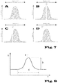
- a “profiled light beam” with an “inhomogeneous beam profile” is understood to mean a conical light beam with an in particular approximately Gaussian or leptokurtic intensity profile (Gaussian beam).
- Gaussian beam Gaussian or leptokurtic intensity profile
- a light cone with the highest intensity is in the optical axis, that is to say in the center of the conical light beam, which falls towards the edge of the light beam.
- Light sources which are readily suitable for generating such a light cone are preferably selected from the group of light-emitting diodes (LED) and semiconductor laser diodes. In a first variant, this is an essentially planar LED light field with an integrated, in a manner known per se, the is usually called cast, condenser lens.
- specific microlenses are provided for beam shaping in order to obtain the beam profiles; these are preferably selected from aspheric lenses and axicon lenses.
- the profiled light beam is projected onto a sensor surface of the opposite light sensor, which detects the entire beam profile of the incident light beam and integrates its intensity over its extent in the projection surface.
- the light sensor thus generates a sensor current which corresponds to the integrated beam intensity.
- the dispensed liquid drop or liquid jet breaks through the light beam of the light barrier unit arranged directly on the dosing channel according to the invention, whereby the light sensor registers a drop in the light intensity on its sensor surface illuminated with the profiled light beam.
- the drop in luminous flux i.e. the degree of shadowing on the sensor, depends on the point within the profiled light beam at which the drop or beam interrupts it.
- the maximum shading ie the maximum reduction in the luminous flux, occurs when the light beam is interrupted along its axis, ie in the middle. In the preferred embodiment of the method, this maximum shading characterizes the ideal direction or target position of the dispensed liquid drop or jet.
- this light barrier unit allows the position and direction of the dispensed liquid drop or liquid jet and the quality of the liquid dispensing to be monitored simply and at the same time with sufficient accuracy.
- the programmed evaluation unit (analogue computer or digital program computer) enables the deviation of the type and quality of the liquid delivery from a desired ideal to be evaluated via the change in the sensor current over time when the liquid droplet or liquid jet passes through the light beam. This In the simplest case, the analysis is as follows: The further the liquid droplet or liquid jet deviates from the ideal center position (ideal direction), the smaller the change in the sensor current due to the shading of the profiled light cone. This functional relationship is in the Figures 7A to 7D explained graphically.
- the arrangement according to the invention in the light barrier unit allows the determination of the quality of the dispensed drop of liquid or, in particular, the jet of liquid if the course of the sensor current over time is registered during the shadowing of the light beam of the light barrier unit by the drop or jet of liquid: there are significant deviations in the expected signal curve.
- the parameter of the signal analysis according to the invention is here in particular the temporal signal variance of the sensor signal, in particular at the time intervals in which the metered drops or rays pass through the light barrier unit(s).
- a larger signal variance indicates a jet disturbance, for example, non-uniform jet shape or jet direction (broken jet, jet too wide, deflected jet) or non-uniform drop formation (drop too large, non-uniform or "breaking up").
- each dosing channel i.e. each needle or nozzle of the micro-dosing device
- the light barrier unit is arranged together on a common carrier, preferably several such light barrier units are arranged next to each other and preferably regularly spaced apart in a row or in a grid.
- the Carrier arranged directly at the ends of the dosing channels, that is, needles or nozzles of the micro-dosing device.
- This allows a compact and at the same time mechanically stable configuration of an integral "sensor plate” made up of a large number of light barrier units which are arranged together on a common carrier.
- the carrier or the carrier plate each has a window through which the liquid droplet or jet emerging from the nozzle or needle can pass.
- a beam-shaping aperture or screen is arranged per light barrier unit between the light source and the light sensor for the purpose of shading unnecessary beam components, primarily to improve the signal quality of the sensor signal.
- the aperture shields the cone of light emerging from the light source to such an extent that just a cone of light is retained which covers the sensor surface of the light sensor, with the width of the cone of light at the point where the released liquid passes through being always greater than the width or dimensions of the drop of liquid passing through or ray (see figure 12 ).
- the panel can be designed as part of the housing or support, on which the light barrier unit is arranged in each case. This allows a compact and at the same time mechanically stable design of the integral “sensor plate”.
- Deviations from the ideal direction of the liquid drops or jets in the direction of the axis of the light beam cannot be easily detected by a single intensity measurement. However, by intelligently comparing several measured values and assuming that the majority of the liquid droplets or jets are emitted in the ideal position, it is possible to draw conclusions about incorrect positioning, even in the longitudinal direction of the light beam. This is because, according to the invention, the light beam is divergent and has a conical spread. In a preferred embodiment, however, the device has at least two independent light barrier units per dosing channel, the light beams of which are at an angle to one another in order to be able to more precisely detect two spatial directions of the positional deviation of liquid droplets or liquid jets.
- At least two, preferably exactly two, separate light barrier units are assigned directly to each dosing channel
- the two light barrier units each consist of a light source and a light sensor.
- the two light barrier units are arranged relative to one another in such a way that their light beams are at an angle to one another, at least in the plane transverse to the propagation direction or ideal direction of the liquid drops or liquid jets to be checked.
- the angle of the light beams to one another in this plane is preferably approximately 90°, alternatively preferably approximately 60°.
- the angle of the light beams to one another (in this plane) is approximately 30° to 150°, preferably 45° to 135°, more preferably 60° to 120°.
- the device according to the invention contains a programmed evaluation unit for the purpose of evaluation and in particular for controlling or regulating the dispensing behavior of the respective dosing channel of the microdosing device, which is connected at least to the respective light sensor and is suitable, by means of corresponding current-voltage converters and measuring amplifiers, high - and/or bandpass filter, to obtain a processed, conditioned and preferably time-resolved sensor signal, which represents the integrated intensity of the beam profile incident on the respective sensor surface.
- the signal parameters that can be evaluated are the signal profile: pulse length, pulse height, pulse flank (slope), the repetition rate, the frequency spectrum, particularly high-frequency components, preferably determined using suitable filters or by Fourier transformation, and the statistical signal variance.
- the offset or bias that can occur as a result of long-term drift on the sensors or misalignment of the light path on the light barrier units can also be recorded. If necessary, this can be compensated for by filters in the analog measuring chain and/or by sliding offset compensation.
- the programmed evaluation unit preferably also contains a computing unit with a memory unit for determining and evaluating the time profile of the light intensity on the sensor surface and/or for determining the difference in intensity on the sensor surface, once at the point in time when the liquid droplet or liquid jet passes through the light beam and once at the same time the point in time immediately before or after this event (undisturbed light beam).
- the evaluation unit preferably has a signaling or control device for signaling the deviation of the temporal intensity profile of the light intensity measured on the sensor from a predeterminable or pre-stored "ideal" intensity profile and/or for signaling the deviation from a pre-determinable, pre-stored intensity difference and/or for generating a suitable control signal, especially to compensate for an identified control deviation.
- the evaluation unit in particular in connection with the computing unit and memory unit, is programmed in such a way that, in order to control the position of the liquid droplet or jet of liquid dispensed at the channels, according to the criteria described herein, the average maximum deviation of the processed sensor signal, i.e. the intensity profile, indicates the ideal position of the liquid drop or jet when the liquid drop or jet passes through the respective light beam and a respective reduction in the amplitude swing below a predeterminable threshold value indicates a deviation or change in direction of the liquid drop or jet dispensed from this ideal position.
- the average maximum deviation of the processed sensor signal i.e. the intensity profile
- the device according to the invention additionally has at least one signal return line, in which the programmed evaluation unit is connected, in particular via the signal or control device, to an actuator on the micro-dosing device for controlling the delivery of the liquid drop or jet from the micro-dosing device based on preset values, which mean the ideal position or ideal quality of a dispensed liquid droplet or liquid jet.
- the control is used to automatically compensate for system-related deviations in the liquid delivery at the respective dosing channels, needles or nozzles during operation using suitable actuators.
- Suitable manipulated variables are amplitude and/or pressure on the respective actuator or dosing head, which triggers the dispensing of liquid at the dosing channel.
- An alternative or additional manipulated variable is the frequency at which liquid delivery is triggered.
- An alternative or additional manipulated variable is the duration of the triggering of the liquid delivery.
- An alternative or additional variable is the nozzle geometry.
- An alternative or additional manipulated variable is a triggerable measure for cleaning the nozzle or needle, for example via additionally triggerable pressure waves, which drive out any accumulated contamination or blockages of the nozzle or needle.
- Suitable actuators and control elements are preferably piezoelectric actuators, alternatively electromagnetic actuators are preferred.
- An essential aspect of the present invention is also the structurally simple, integral structure of the respective light barrier units on a common carrier, which facilitates cleaning, interchangeability and at the same time the precision of the measurement. It becomes conscious on complicated optical Devices omitted.
- the intelligent programming of the evaluation unit in conjunction with the light barrier unit with a profiled light beam and an integrating sensor surface provides a simple yet precise measuring instrument that can reliably determine the quality of the liquid metering at the respective metering channels, display it and, in particular, compensate for a target state by means of suitable feedback .
- This embodiment advantageously allows the provision of a fully automatic, autonomous, in particular self-adapting, micro-dosing device, which enables an uninterrupted, fully automatic dosing operation.
- This is particularly important in systems for the automatic cultivation of cells and tissues, in which interventions by the machine operator should always be avoided, if only because of the sterility and purity that must be maintained, but also because of the operating conditions that must be maintained, in particular ambient air, gassing and temperature.
- the optical control device according to the invention therefore allows the provision of multi-channel micro-dosing devices which repeatedly control small amounts of liquids, especially liquid drops or liquid jets, and can deliver them with consistent quality, specifically in uninterrupted automated operation.
- a further object of this invention is an improved multi-channel micro-dosing device for automatic dosing of liquid in the nanoliter or microliter range by means of repetitive delivery of liquid droplets or liquid jets of small volume, which is suitable for uninterrupted automatic operation.
- This contains the optical control device of the present invention as an integral part, especially as an integral sensor plate arranged directly on the dosing channels with a plurality of light barrier units carried on a common carrier.
- a further object of the invention is a method for the controlled intermittent dispensing of liquid droplets or liquid jets on or by means of a multi-channel micro-dosing device, in particular using it of the optical control device according to this invention.
- the method contains at least the following steps: In a first step, a short-term release of a liquid droplet or jet of small volume is triggered at the respective metering channels, needles or nozzles of the micrometering device.
- the light intensities on the sensor surface of a light sensor which is illuminated by a light beam with an inhomogeneous beam profile and is assigned to the channels of the microdosing device, are recorded over time when the liquid dispensed passes through the respective light beam.
- the light intensities registered over time are automatically evaluated using predefined intensity values or intensity profiles.
- at least one control signal or warning signal is emitted, which is used to control the delivery of the liquid from the micro-dosing device in a closed control loop and/or to signal an incorrect dosing at the respective channel of the micro-dosing device.
- the maximum amplitude swing of the intensity signal when the liquid released passes through the respective light beam indicates the ideal direction of the liquid drop or jet and a reduction in the amplitude swing, in particular compared to an averaged maximum amplitude swing, indicates a deviation in the position or direction of the liquid droplet or jet therefrom.
- a deviation of the amplitude swing of the intensity signal when the liquid emitted passes through the respective light beam in particular opposite an averaged maximum amplitude swing, and in particular the temporary reduction of the Amplitude swing or a fluctuating signal amplitude or a temporary absence of an amplitude swing of the intensity when triggering the liquid delivery indicates incorrect dosing at the respective channel.
- figure 1 shows a schematic representation of the overall structure of a microdosing device with an optical control device.
- the micro-dosing device (20) has a driver or dosing head (24) for each dosing channel (22).
- the dosing head is suitable for exerting recurring pressure pulses on the liquid (25) supplied to the dosing channel (22) in order to expel the liquid from the nozzle (23).
- the optical arrangement (10) according to the invention is positioned directly below the outlet or nozzle (23) of the dosing channel (22).
- Light source (42) and sensor (46) together form the light barrier unit (40), which is present at least once for each dosing channel (22) of the microdosing device (20).
- the light barrier units (40) are arranged on the common carrier (30) and form the optical device (10) according to the invention, in particular in a multi-channel design.
- the light beam (44) of the light barrier unit (40) is oriented in such a way that it is interrupted in a crossing manner by the liquid droplets or liquid jet (26) that can be dispensed from the microdosing device (20).
- the profiled light beam (44) is wider at this point, ie more extensive, than the liquid drop or liquid jet (26) passing through.
- the liquid drop or jet (26) preferably runs perpendicularly in the vertical direction following the gravitational vector.
- the liquid (25) that can be dispensed from the micro-dosing device (20) is dosed into the trough or depression (80).
- This is preferably part of a microtiter plate or multiwell plate with a plurality of wells arranged side by side in a regular manner or indentations (80).
- each light barrier unit (40) is fed via a line (48) to an evaluation unit (60), which is programmed in such a way that the deviation in the light intensity on the sensor surface of the sensor (46) when the liquid droplet or -Beam (26) by the profiled light beam (44) can be used by comparison with previously recorded intensity values and / or by comparison with preset intensity values or temporal intensity curves to assess the quality, the dosing direction, and / or incorrect dosing.
- the programmed evaluation unit (60) preferably has a computing unit (64) with an associated memory unit (62) which stores the measured values of the light intensity.
- a return line (68) is preferably provided, via which at least one control signal (correcting variable) is transmitted from the programmed evaluation unit (60) to at least one actuator (28) on the micro-dosing device (20), which signals one or more parameters of the liquid dosing of the respective dosing channel (22) controls and in particular automatically regulates depending on the detected quality of the liquid delivery.
- the actuator (28) is a pressure control device which determines the amplitude and frequency of the pressurization when the liquid (25) is dispensed from the metering channel (22).
- FIG 2 shows a schematic representation of a pair of light barrier units (40) according to the invention in the viewing direction of the dispensed liquid (26).
- a light source (42) generates a beam cone (44) with an inhomogeneous, in particular Gaussian intensity profile, which is projected onto the sensor surface (48) of an opposite sensor (46).
- a second light barrier unit (40) identical thereto two light beams (44) running essentially perpendicularly crossed are designed for improved position determination of the liquid droplet or liquid jet (26) passing through.
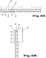
- Figure 3 and Figure 4 each show schematic representations of specific configurations of multi-channel micro-dosing devices (20) each with a plurality of side-by-side dosing channels (22) to be operated in parallel in the form of nozzles or needles.
- At least one light barrier unit consisting of a light source (42) and a light sensor (46) is arranged directly at the tip of each dosing channel (22), each together on a carrier (30).
- the carrier (30) is in the form of a continuous plate which has a window (32) at the points where the dispensed drops or jets of liquid pass through.
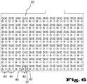
- Figures 5A and 5B and figure 6 each show schematic top views of variants of devices according to the invention in a preferred embodiment as integrated sensor plates with several light barrier units (40) to be operated in parallel and regularly spaced apart from one another, each consisting of a light source (43) and an associated light sensor (46), on a common carrier (30 ) and with intervening window (32) for the passage of discharged drops or jets of liquid.
- figure 8 shows essential parameters that are used in the programmed evaluation unit of the device according to the invention in the course of time of the respective sensor signal to determine the quality of the liquid metering.
- the waveform of the signal voltage over time is proportional to the inverted sensor current: a high voltage indicates a lower radiation intensity on the sensor surface.
- a voltage rise occurs as the light beam breaks through the dispensed droplet or jet of liquid.
- the steepness and time course of the voltage increase (a) provide direct information about the quality of the liquid metering, in particular when dispensing jets of liquid, the quality, in particular the uniformity of the liquid jet can be assessed here.
- the level (b) of the signal amplitude shows in particular, as in Figure 7A to 7D shown, indicates the position of the dispensed liquid droplet or jet.
- Measurement setup Setup of the detection unit on an XYZ table that can be adjusted in three spatial directions below a dosing channel. The needle position in relation to the optical axis was adjusted here based on the shadow cast by the dosing needle: the needle first hung into the light barrier - recognizable in the sensor signal as a reduction in the sensor signal - and was then pulled up to the upper edge of the light beam of the light barrier.
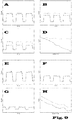
- the signals each show three releases of liquid when the light beam passes through the center ideally ( Figure 9A ) and when the liquid jets are shifted from the ideal position, i.e. in the event of incorrect dosing ( Figures 9B and C).
- Figure 9D shows the dependence of the signal amplitude on the position or deflection of the liquid jet.
- the Figures 9A to D show the situation when the liquid jet is shifted by about 90°, i.e. perpendicular to the light beam of the first Light barrier unit and about 0 °, that is, along the optical axis of the light beam of the second light barrier unit.
- Figure 9D shows how Figure 9D also leads to a drop in signal amplitude in the second unit (see dashed line).
- Figures 9E to H show the same experimental procedure with a diagonal displacement of the liquid jets, deflection of about 45° to the light beam of the first light barrier unit and about 45° to the light beam of the second light barrier unit.
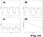
- figure 10 shows measured electrical signals analogous to figure 9 .
- Figure 10A a substantially undisturbed ideal jet path of intermittently discharged liquid jets is shown.
- Figures 10B to C show various "defective" dosing channels that "splash" at different rates.
- the quality i.e. in particular the continuity and constant volume of the dosed liquid, is increasing Figures 10B and C away. This suggests an incorrect dosage.
- Figure 10D shows the dependency of the signal quality, which is determined via the signal variance.
- the decisive signal parameter for evaluating the beam quality is the signal variance (in practice: noise on the peaks).
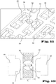
- FIG 11 shows a schematic oblique view of a section of the sensor plate according to the invention figure 6 :
- Light sources (42) with opposing light sensors (46) are applied as SMD elements to a carrier (30), which simultaneously contains the electrical contact and the conductor tracks.
- the carrier (30) contains further electronic components (38) for signal conditioning, which are applied in an SMD design or are integrated in the carrier (30) in a hybrid design.
- the carrier (30) contains a carrier frame (34) with respective windows (32) through which the liquid droplets or jets can pass.
- the carrier frame (34) also serves as an aperture for beam shadowing to improve the signal quality at the sensor (46).
- figure 12 shows a schematic plan view of the arrangement according to FIG figures 5 , 6 and 11 a single light barrier unit consisting of a light source (42) and opposite sensor (46) with sensor surface (48) and intermediate support frame (34) with window (32) through which the liquid drop or - jet (26) can pass.
- the carrier frame (34) also serves as an aperture for beam shadowing to improve the signal quality at the sensor (46).
- the jet width (A) generated by the aperture is always greater there than the width (B) of the liquid droplet or jet (26) passing through.
- Dimension A describes the panel width. This is approx. 2 to 3 times larger than the expected jet or droplet diameter (dimension B).
- Sensor (46) and LED light source (42) are mounted at a distance of about 2 to 4 mm.
- dimension A is about 0.6 mm
- dimension A is approximately 1 mm
Landscapes
- Chemical & Material Sciences (AREA)
- Health & Medical Sciences (AREA)
- Life Sciences & Earth Sciences (AREA)
- Engineering & Computer Science (AREA)
- General Health & Medical Sciences (AREA)
- Analytical Chemistry (AREA)
- Biochemistry (AREA)
- Bioinformatics & Cheminformatics (AREA)
- Organic Chemistry (AREA)
- Zoology (AREA)
- Wood Science & Technology (AREA)
- Physics & Mathematics (AREA)
- General Physics & Mathematics (AREA)
- Immunology (AREA)
- Pathology (AREA)
- Clinical Laboratory Science (AREA)
- Chemical Kinetics & Catalysis (AREA)
- General Engineering & Computer Science (AREA)
- Genetics & Genomics (AREA)
- Biotechnology (AREA)
- Microbiology (AREA)
- Sustainable Development (AREA)
- Biomedical Technology (AREA)
- Computer Hardware Design (AREA)
- Quality & Reliability (AREA)
- Spectroscopy & Molecular Physics (AREA)
- Dispersion Chemistry (AREA)
- Hematology (AREA)
- Optics & Photonics (AREA)
- Automatic Analysis And Handling Materials Therefor (AREA)
- Apparatus Associated With Microorganisms And Enzymes (AREA)
- Investigating Materials By The Use Of Optical Means Adapted For Particular Applications (AREA)
- Sampling And Sample Adjustment (AREA)
- Physical Or Chemical Processes And Apparatus (AREA)
- Investigating Or Analysing Materials By Optical Means (AREA)
Applications Claiming Priority (1)
| Application Number | Priority Date | Filing Date | Title |
|---|---|---|---|
| DE102016215240.8A DE102016215240B3 (de) | 2016-08-16 | 2016-08-16 | Mikrodosiereinrichtung und automatisches Mikrodosierverfahren |
Publications (2)
| Publication Number | Publication Date |
|---|---|
| EP3285074A1 EP3285074A1 (de) | 2018-02-21 |
| EP3285074B1 true EP3285074B1 (de) | 2022-01-12 |
Family
ID=59655889
Family Applications (1)
| Application Number | Title | Priority Date | Filing Date |
|---|---|---|---|
| EP17185313.8A Active EP3285074B1 (de) | 2016-08-16 | 2017-08-08 | Mikrodosiereinrichtung und automatisches mikrodosierverfahren |
Country Status (5)
| Country | Link |
|---|---|
| US (1) | US11280806B2 (enExample) |
| EP (1) | EP3285074B1 (enExample) |
| JP (2) | JP2018028540A (enExample) |
| CN (1) | CN107765022B (enExample) |
| DE (1) | DE102016215240B3 (enExample) |
Families Citing this family (6)
| Publication number | Priority date | Publication date | Assignee | Title |
|---|---|---|---|---|
| DE102016215240B3 (de) * | 2016-08-16 | 2017-10-12 | Fraunhofer-Gesellschaft zur Förderung der angewandten Forschung e.V. | Mikrodosiereinrichtung und automatisches Mikrodosierverfahren |
| US10512911B1 (en) * | 2018-12-07 | 2019-12-24 | Ultima Genomics, Inc. | Implementing barriers for controlled environments during sample processing and detection |
| LU500832B1 (en) | 2021-11-06 | 2023-05-15 | Dispendix Gmbh | Carrier Device for a Dispensing Device |
| CN114234538B (zh) * | 2021-12-20 | 2023-03-10 | 苏州热立方新能源有限公司 | 一种霜层识别装置及使用方法和探针自动除霜系统 |
| WO2025183831A1 (en) * | 2024-02-26 | 2025-09-04 | Ventana Medical Systems, Inc. | Precision dispenser actuator |
| CN119286638A (zh) * | 2024-09-25 | 2025-01-10 | 吉林省特医食品生物科技有限公司 | 一种自动滴油装置及控制系统 |
Family Cites Families (17)
| Publication number | Priority date | Publication date | Assignee | Title |
|---|---|---|---|---|
| US4328800A (en) * | 1980-10-30 | 1982-05-11 | Alvin J. Marx | Automated intravenous fluid regulating and administering apparatus |
| JPH05223830A (ja) * | 1991-04-04 | 1993-09-03 | Olympus Optical Co Ltd | 分注量検出装置および方法 |
| US6878554B1 (en) * | 2000-03-20 | 2005-04-12 | Perkinelmer Las, Inc. | Method and apparatus for automatic pin detection in microarray spotting instruments |
| JP3703418B2 (ja) * | 2001-10-03 | 2005-10-05 | キヤノン株式会社 | 飛翔物体位置測定方法及び装置 |
| JP3809086B2 (ja) | 2001-10-12 | 2006-08-16 | オリンパス株式会社 | 液体分注装置 |
| JP2005134167A (ja) | 2003-10-29 | 2005-05-26 | National Institute Of Advanced Industrial & Technology | スポッタ装置 |
| JP4496955B2 (ja) * | 2004-12-28 | 2010-07-07 | セイコーエプソン株式会社 | 液滴吐出装置 |
| IL166400A (en) * | 2005-01-20 | 2012-07-31 | Flowsense Ltd | Optical drop detection system |
| US7342670B2 (en) * | 2005-10-19 | 2008-03-11 | Labcoat, Ltd. | In-flight drop location verification system |
| WO2007056490A2 (en) * | 2005-11-08 | 2007-05-18 | Incom, Inc. | Fiber optic interrogated microslide, microslide kits and uses thereof |
| US8212999B2 (en) * | 2007-09-27 | 2012-07-03 | Fujifilm Corporation | Liquid droplet measurement apparatus and liquid droplet measurement method |
| JP4974947B2 (ja) | 2007-09-27 | 2012-07-11 | 富士フイルム株式会社 | 液滴測定装置 |
| WO2010044765A1 (en) * | 2008-10-15 | 2010-04-22 | Hewlett-Packard Development Company, L. P. | Method of detecting drops |
| US8201913B2 (en) * | 2009-04-20 | 2012-06-19 | Hewlett-Packard Development Company, L.P. | Drop detector |
| US8912007B2 (en) * | 2013-01-22 | 2014-12-16 | Tecan Trading Ag | Optical measuring apparatus and method for the analysis of samples contained in liquid drops |
| EP2974566B1 (en) * | 2013-03-13 | 2018-05-09 | Mycronic AB | Method and device for jetting droplets |
| DE102016215240B3 (de) * | 2016-08-16 | 2017-10-12 | Fraunhofer-Gesellschaft zur Förderung der angewandten Forschung e.V. | Mikrodosiereinrichtung und automatisches Mikrodosierverfahren |
-
2016
- 2016-08-16 DE DE102016215240.8A patent/DE102016215240B3/de active Active
-
2017
- 2017-08-08 EP EP17185313.8A patent/EP3285074B1/de active Active
- 2017-08-10 US US15/673,528 patent/US11280806B2/en active Active
- 2017-08-15 JP JP2017156707A patent/JP2018028540A/ja active Pending
- 2017-08-16 CN CN201710700710.9A patent/CN107765022B/zh active Active
-
2022
- 2022-07-08 JP JP2022110380A patent/JP7395667B2/ja active Active
Also Published As
| Publication number | Publication date |
|---|---|
| JP2022163728A (ja) | 2022-10-26 |
| US11280806B2 (en) | 2022-03-22 |
| CN107765022B (zh) | 2023-02-17 |
| CN107765022A (zh) | 2018-03-06 |
| US20180067142A1 (en) | 2018-03-08 |
| DE102016215240B3 (de) | 2017-10-12 |
| JP2018028540A (ja) | 2018-02-22 |
| EP3285074A1 (de) | 2018-02-21 |
| JP7395667B2 (ja) | 2023-12-11 |
Similar Documents
| Publication | Publication Date | Title |
|---|---|---|
| EP3285074B1 (de) | Mikrodosiereinrichtung und automatisches mikrodosierverfahren | |
| DE10052819B4 (de) | Pipettensystem und Pipettenarray sowie Verfahren zum Befüllen eines Pipettensystems | |
| DE10236029A1 (de) | Einrichtung zum Dispensieren und Beobachten der Lumineszenz von Einzelproben in Multiprobenanordnungen | |
| DE102006015535A1 (de) | Verfahren und Vorrichtung zur Analyse von Isotopenverhältnissen | |
| DE20018628U1 (de) | Probenabgabevorrichtung | |
| EP3705889A1 (de) | Eieruntersuchungseinrichtung | |
| DE69827952T2 (de) | Mikrovolumenfluessigkeitshandhabungssystem | |
| EP3112859B1 (de) | Probenhalter einer analyseeinrichtung für die elementaranalyse und analyseeinrichtung für die elementaranalyse | |
| DE19727484C2 (de) | Verfahren und Vorrichtung zum Vermessen eines aus einer Sprühdüse austretenden Sprühstrahls | |
| DE10255595A1 (de) | Mehrkanaldosiervorrichtung mit automatischer Kalibrierung | |
| WO2014012697A1 (de) | Vorrichtung zum befüllen von behältnissen | |
| DE102017207524B4 (de) | Dosiervorrichtung und damit ausführbares Dosierverfahren | |
| EP3548871B1 (de) | Vorrichtung zur aufnahme vollflächiger bilder einer zellkulturplatte mit einer oder mehreren kavitäten | |
| DE102011000891A1 (de) | Verfahren und Vorrichtung zum Bestimmen mindestens einer Veränderlichen | |
| DE10241545A1 (de) | Vorrichtung zur Überführung eines kontinuierlichen Flüssigkeitsstroms in einen Strom aus Flüssigkeitströpfchen | |
| EP1038184B1 (de) | Vorrichtung und verfahren zur bildaufnahme an tropfenerzeugenden dispensierköpfen | |
| EP2006022B1 (de) | Probenbehandlungsanordnung für eine Flüssigkeitsdosiervorrichtung | |
| EP3910314B1 (de) | Verfahren und vorrichtung zur analyse der wechselwirkung zwischen einer oberfläche einer probe und einer flüssigkeit | |
| EP1856508A1 (de) | Verfahren und vorrichtung zur messung einer austretenden flüssigkeit | |
| EP1034432B1 (de) | Verfahren und vorrichtung zur bewegungserfassung an mikropartikeln | |
| DE19510402C2 (de) | Verfahren und Einrichtung zur optischen Erfassung eines Fluiddots auf einem Substrat | |
| EP4058785B1 (de) | Sensor und vorrichtung zur erfassung des kristallisationsgrades | |
| DE102018202521B4 (de) | Dosiervorrichtung | |
| WO2025223643A1 (de) | Adapter zur aufnahme einer pipettenspitze, verfahren zur verwendung eines adapters sowie pipettiervorrichtung | |
| EP2191341B1 (de) | Stofftransport und ereigniskontrolle in systemen mit piezoelektrisch aktivierter tröpfchenemission und kombinationsmöglichkeiten von trägermatrix und zu dosierendem stoff |
Legal Events
| Date | Code | Title | Description |
|---|---|---|---|
| PUAI | Public reference made under article 153(3) epc to a published international application that has entered the european phase |
Free format text: ORIGINAL CODE: 0009012 |
|
| STAA | Information on the status of an ep patent application or granted ep patent |
Free format text: STATUS: THE APPLICATION HAS BEEN PUBLISHED |
|
| AK | Designated contracting states |
Kind code of ref document: A1 Designated state(s): AL AT BE BG CH CY CZ DE DK EE ES FI FR GB GR HR HU IE IS IT LI LT LU LV MC MK MT NL NO PL PT RO RS SE SI SK SM TR |
|
| AX | Request for extension of the european patent |
Extension state: BA ME |
|
| STAA | Information on the status of an ep patent application or granted ep patent |
Free format text: STATUS: REQUEST FOR EXAMINATION WAS MADE |
|
| 17P | Request for examination filed |
Effective date: 20180821 |
|
| RBV | Designated contracting states (corrected) |
Designated state(s): AL AT BE BG CH CY CZ DE DK EE ES FI FR GB GR HR HU IE IS IT LI LT LU LV MC MK MT NL NO PL PT RO RS SE SI SK SM TR |
|
| RIC1 | Information provided on ipc code assigned before grant |
Ipc: B01L 3/02 20060101ALN20210709BHEP Ipc: B41J 2/045 20060101ALN20210709BHEP Ipc: B41J 2/21 20060101ALN20210709BHEP Ipc: G01N 35/10 20060101AFI20210709BHEP |
|
| GRAP | Despatch of communication of intention to grant a patent |
Free format text: ORIGINAL CODE: EPIDOSNIGR1 |
|
| STAA | Information on the status of an ep patent application or granted ep patent |
Free format text: STATUS: GRANT OF PATENT IS INTENDED |
|
| INTG | Intention to grant announced |
Effective date: 20210903 |
|
| GRAS | Grant fee paid |
Free format text: ORIGINAL CODE: EPIDOSNIGR3 |
|
| GRAA | (expected) grant |
Free format text: ORIGINAL CODE: 0009210 |
|
| STAA | Information on the status of an ep patent application or granted ep patent |
Free format text: STATUS: THE PATENT HAS BEEN GRANTED |
|
| AK | Designated contracting states |
Kind code of ref document: B1 Designated state(s): AL AT BE BG CH CY CZ DE DK EE ES FI FR GB GR HR HU IE IS IT LI LT LU LV MC MK MT NL NO PL PT RO RS SE SI SK SM TR |
|
| REG | Reference to a national code |
Ref country code: GB Ref legal event code: FG4D Free format text: NOT ENGLISH |
|
| REG | Reference to a national code |
Ref country code: CH Ref legal event code: EP |
|
| REG | Reference to a national code |
Ref country code: DE Ref legal event code: R096 Ref document number: 502017012431 Country of ref document: DE |
|
| REG | Reference to a national code |
Ref country code: IE Ref legal event code: FG4D Free format text: LANGUAGE OF EP DOCUMENT: GERMAN |
|
| REG | Reference to a national code |
Ref country code: AT Ref legal event code: REF Ref document number: 1462730 Country of ref document: AT Kind code of ref document: T Effective date: 20220215 |
|
| REG | Reference to a national code |
Ref country code: SE Ref legal event code: TRGR |
|
| RAP4 | Party data changed (patent owner data changed or rights of a patent transferred) |
Owner name: FRAUNHOFER-GESELLSCHAFT ZUR FOERDERUNG DER ANGEWANDTEN FORSCHUNG E.V. |
|
| REG | Reference to a national code |
Ref country code: NL Ref legal event code: FP |
|
| REG | Reference to a national code |
Ref country code: LT Ref legal event code: MG9D |
|
| PG25 | Lapsed in a contracting state [announced via postgrant information from national office to epo] |
Ref country code: RS Free format text: LAPSE BECAUSE OF FAILURE TO SUBMIT A TRANSLATION OF THE DESCRIPTION OR TO PAY THE FEE WITHIN THE PRESCRIBED TIME-LIMIT Effective date: 20220112 Ref country code: PT Free format text: LAPSE BECAUSE OF FAILURE TO SUBMIT A TRANSLATION OF THE DESCRIPTION OR TO PAY THE FEE WITHIN THE PRESCRIBED TIME-LIMIT Effective date: 20220512 Ref country code: NO Free format text: LAPSE BECAUSE OF FAILURE TO SUBMIT A TRANSLATION OF THE DESCRIPTION OR TO PAY THE FEE WITHIN THE PRESCRIBED TIME-LIMIT Effective date: 20220412 Ref country code: LT Free format text: LAPSE BECAUSE OF FAILURE TO SUBMIT A TRANSLATION OF THE DESCRIPTION OR TO PAY THE FEE WITHIN THE PRESCRIBED TIME-LIMIT Effective date: 20220112 Ref country code: HR Free format text: LAPSE BECAUSE OF FAILURE TO SUBMIT A TRANSLATION OF THE DESCRIPTION OR TO PAY THE FEE WITHIN THE PRESCRIBED TIME-LIMIT Effective date: 20220112 Ref country code: ES Free format text: LAPSE BECAUSE OF FAILURE TO SUBMIT A TRANSLATION OF THE DESCRIPTION OR TO PAY THE FEE WITHIN THE PRESCRIBED TIME-LIMIT Effective date: 20220112 Ref country code: BG Free format text: LAPSE BECAUSE OF FAILURE TO SUBMIT A TRANSLATION OF THE DESCRIPTION OR TO PAY THE FEE WITHIN THE PRESCRIBED TIME-LIMIT Effective date: 20220412 |
|
| PG25 | Lapsed in a contracting state [announced via postgrant information from national office to epo] |
Ref country code: PL Free format text: LAPSE BECAUSE OF FAILURE TO SUBMIT A TRANSLATION OF THE DESCRIPTION OR TO PAY THE FEE WITHIN THE PRESCRIBED TIME-LIMIT Effective date: 20220112 Ref country code: LV Free format text: LAPSE BECAUSE OF FAILURE TO SUBMIT A TRANSLATION OF THE DESCRIPTION OR TO PAY THE FEE WITHIN THE PRESCRIBED TIME-LIMIT Effective date: 20220112 Ref country code: GR Free format text: LAPSE BECAUSE OF FAILURE TO SUBMIT A TRANSLATION OF THE DESCRIPTION OR TO PAY THE FEE WITHIN THE PRESCRIBED TIME-LIMIT Effective date: 20220413 Ref country code: FI Free format text: LAPSE BECAUSE OF FAILURE TO SUBMIT A TRANSLATION OF THE DESCRIPTION OR TO PAY THE FEE WITHIN THE PRESCRIBED TIME-LIMIT Effective date: 20220112 |
|
| PG25 | Lapsed in a contracting state [announced via postgrant information from national office to epo] |
Ref country code: IS Free format text: LAPSE BECAUSE OF FAILURE TO SUBMIT A TRANSLATION OF THE DESCRIPTION OR TO PAY THE FEE WITHIN THE PRESCRIBED TIME-LIMIT Effective date: 20220512 |
|
| REG | Reference to a national code |
Ref country code: DE Ref legal event code: R097 Ref document number: 502017012431 Country of ref document: DE |
|
| PG25 | Lapsed in a contracting state [announced via postgrant information from national office to epo] |
Ref country code: SM Free format text: LAPSE BECAUSE OF FAILURE TO SUBMIT A TRANSLATION OF THE DESCRIPTION OR TO PAY THE FEE WITHIN THE PRESCRIBED TIME-LIMIT Effective date: 20220112 Ref country code: SK Free format text: LAPSE BECAUSE OF FAILURE TO SUBMIT A TRANSLATION OF THE DESCRIPTION OR TO PAY THE FEE WITHIN THE PRESCRIBED TIME-LIMIT Effective date: 20220112 Ref country code: RO Free format text: LAPSE BECAUSE OF FAILURE TO SUBMIT A TRANSLATION OF THE DESCRIPTION OR TO PAY THE FEE WITHIN THE PRESCRIBED TIME-LIMIT Effective date: 20220112 Ref country code: EE Free format text: LAPSE BECAUSE OF FAILURE TO SUBMIT A TRANSLATION OF THE DESCRIPTION OR TO PAY THE FEE WITHIN THE PRESCRIBED TIME-LIMIT Effective date: 20220112 Ref country code: DK Free format text: LAPSE BECAUSE OF FAILURE TO SUBMIT A TRANSLATION OF THE DESCRIPTION OR TO PAY THE FEE WITHIN THE PRESCRIBED TIME-LIMIT Effective date: 20220112 Ref country code: CZ Free format text: LAPSE BECAUSE OF FAILURE TO SUBMIT A TRANSLATION OF THE DESCRIPTION OR TO PAY THE FEE WITHIN THE PRESCRIBED TIME-LIMIT Effective date: 20220112 |
|
| PLBE | No opposition filed within time limit |
Free format text: ORIGINAL CODE: 0009261 |
|
| STAA | Information on the status of an ep patent application or granted ep patent |
Free format text: STATUS: NO OPPOSITION FILED WITHIN TIME LIMIT |
|
| PG25 | Lapsed in a contracting state [announced via postgrant information from national office to epo] |
Ref country code: AL Free format text: LAPSE BECAUSE OF FAILURE TO SUBMIT A TRANSLATION OF THE DESCRIPTION OR TO PAY THE FEE WITHIN THE PRESCRIBED TIME-LIMIT Effective date: 20220112 |
|
| 26N | No opposition filed |
Effective date: 20221013 |
|
| PG25 | Lapsed in a contracting state [announced via postgrant information from national office to epo] |
Ref country code: SI Free format text: LAPSE BECAUSE OF FAILURE TO SUBMIT A TRANSLATION OF THE DESCRIPTION OR TO PAY THE FEE WITHIN THE PRESCRIBED TIME-LIMIT Effective date: 20220112 |
|
| PG25 | Lapsed in a contracting state [announced via postgrant information from national office to epo] |
Ref country code: MC Free format text: LAPSE BECAUSE OF FAILURE TO SUBMIT A TRANSLATION OF THE DESCRIPTION OR TO PAY THE FEE WITHIN THE PRESCRIBED TIME-LIMIT Effective date: 20220112 |
|
| PG25 | Lapsed in a contracting state [announced via postgrant information from national office to epo] |
Ref country code: LU Free format text: LAPSE BECAUSE OF NON-PAYMENT OF DUE FEES Effective date: 20220808 |
|
| P01 | Opt-out of the competence of the unified patent court (upc) registered |
Effective date: 20230524 |
|
| PG25 | Lapsed in a contracting state [announced via postgrant information from national office to epo] |
Ref country code: IT Free format text: LAPSE BECAUSE OF FAILURE TO SUBMIT A TRANSLATION OF THE DESCRIPTION OR TO PAY THE FEE WITHIN THE PRESCRIBED TIME-LIMIT Effective date: 20220112 |
|
| PG25 | Lapsed in a contracting state [announced via postgrant information from national office to epo] |
Ref country code: HU Free format text: LAPSE BECAUSE OF FAILURE TO SUBMIT A TRANSLATION OF THE DESCRIPTION OR TO PAY THE FEE WITHIN THE PRESCRIBED TIME-LIMIT; INVALID AB INITIO Effective date: 20170808 |
|
| PG25 | Lapsed in a contracting state [announced via postgrant information from national office to epo] |
Ref country code: CY Free format text: LAPSE BECAUSE OF FAILURE TO SUBMIT A TRANSLATION OF THE DESCRIPTION OR TO PAY THE FEE WITHIN THE PRESCRIBED TIME-LIMIT Effective date: 20220112 |
|
| PG25 | Lapsed in a contracting state [announced via postgrant information from national office to epo] |
Ref country code: MK Free format text: LAPSE BECAUSE OF FAILURE TO SUBMIT A TRANSLATION OF THE DESCRIPTION OR TO PAY THE FEE WITHIN THE PRESCRIBED TIME-LIMIT Effective date: 20220112 |
|
| PG25 | Lapsed in a contracting state [announced via postgrant information from national office to epo] |
Ref country code: TR Free format text: LAPSE BECAUSE OF FAILURE TO SUBMIT A TRANSLATION OF THE DESCRIPTION OR TO PAY THE FEE WITHIN THE PRESCRIBED TIME-LIMIT Effective date: 20220112 |
|
| PG25 | Lapsed in a contracting state [announced via postgrant information from national office to epo] |
Ref country code: MT Free format text: LAPSE BECAUSE OF FAILURE TO SUBMIT A TRANSLATION OF THE DESCRIPTION OR TO PAY THE FEE WITHIN THE PRESCRIBED TIME-LIMIT Effective date: 20220112 |
|
| PGFP | Annual fee paid to national office [announced via postgrant information from national office to epo] |
Ref country code: NL Payment date: 20250821 Year of fee payment: 9 |
|
| PGFP | Annual fee paid to national office [announced via postgrant information from national office to epo] |
Ref country code: DE Payment date: 20250819 Year of fee payment: 9 |
|
| PGFP | Annual fee paid to national office [announced via postgrant information from national office to epo] |
Ref country code: BE Payment date: 20250820 Year of fee payment: 9 Ref country code: GB Payment date: 20250822 Year of fee payment: 9 |
|
| PGFP | Annual fee paid to national office [announced via postgrant information from national office to epo] |
Ref country code: AT Payment date: 20250819 Year of fee payment: 9 Ref country code: FR Payment date: 20250821 Year of fee payment: 9 |
|
| PGFP | Annual fee paid to national office [announced via postgrant information from national office to epo] |
Ref country code: CH Payment date: 20250901 Year of fee payment: 9 Ref country code: SE Payment date: 20250821 Year of fee payment: 9 |
|
| PGFP | Annual fee paid to national office [announced via postgrant information from national office to epo] |
Ref country code: IE Payment date: 20250821 Year of fee payment: 9 |