EP3283695B1 - Saugbagger mit strömungsumkehr sowie verfahren zu dessen steuerung - Google Patents
Saugbagger mit strömungsumkehr sowie verfahren zu dessen steuerung Download PDFInfo
- Publication number
- EP3283695B1 EP3283695B1 EP16717865.6A EP16717865A EP3283695B1 EP 3283695 B1 EP3283695 B1 EP 3283695B1 EP 16717865 A EP16717865 A EP 16717865A EP 3283695 B1 EP3283695 B1 EP 3283695B1
- Authority
- EP
- European Patent Office
- Prior art keywords
- suction
- air
- fan unit
- flow
- opening
- Prior art date
- Legal status (The legal status is an assumption and is not a legal conclusion. Google has not performed a legal analysis and makes no representation as to the accuracy of the status listed.)
- Active
Links
Images

Classifications
-
- E—FIXED CONSTRUCTIONS
- E01—CONSTRUCTION OF ROADS, RAILWAYS, OR BRIDGES
- E01H—STREET CLEANING; CLEANING OF PERMANENT WAYS; CLEANING BEACHES; DISPERSING OR PREVENTING FOG IN GENERAL CLEANING STREET OR RAILWAY FURNITURE OR TUNNEL WALLS
- E01H1/00—Removing undesirable matter from roads or like surfaces, with or without moistening of the surface
- E01H1/08—Pneumatically dislodging or taking-up undesirable matter or small objects; Drying by heat only or by streams of gas; Cleaning by projecting abrasive particles
- E01H1/0827—Dislodging by suction; Mechanical dislodging-cleaning apparatus with independent or dependent exhaust, e.g. dislodging-sweeping machines with independent suction nozzles ; Mechanical loosening devices working under vacuum
- E01H1/0836—Apparatus dislodging all of the dirt by suction ; Suction nozzles
-
- B—PERFORMING OPERATIONS; TRANSPORTING
- B08—CLEANING
- B08B—CLEANING IN GENERAL; PREVENTION OF FOULING IN GENERAL
- B08B5/00—Cleaning by methods involving the use of air flow or gas flow
- B08B5/04—Cleaning by suction, with or without auxiliary action
-
- E—FIXED CONSTRUCTIONS
- E01—CONSTRUCTION OF ROADS, RAILWAYS, OR BRIDGES
- E01H—STREET CLEANING; CLEANING OF PERMANENT WAYS; CLEANING BEACHES; DISPERSING OR PREVENTING FOG IN GENERAL CLEANING STREET OR RAILWAY FURNITURE OR TUNNEL WALLS
- E01H1/00—Removing undesirable matter from roads or like surfaces, with or without moistening of the surface
- E01H1/08—Pneumatically dislodging or taking-up undesirable matter or small objects; Drying by heat only or by streams of gas; Cleaning by projecting abrasive particles
- E01H1/0809—Loosening or dislodging by blowing ; Drying by means of gas streams
-
- E—FIXED CONSTRUCTIONS
- E02—HYDRAULIC ENGINEERING; FOUNDATIONS; SOIL SHIFTING
- E02F—DREDGING; SOIL-SHIFTING
- E02F3/00—Dredgers; Soil-shifting machines
- E02F3/04—Dredgers; Soil-shifting machines mechanically-driven
- E02F3/88—Dredgers; Soil-shifting machines mechanically-driven with arrangements acting by a sucking or forcing effect, e.g. suction dredgers
- E02F3/8816—Mobile land installations
-
- E—FIXED CONSTRUCTIONS
- E02—HYDRAULIC ENGINEERING; FOUNDATIONS; SOIL SHIFTING
- E02F—DREDGING; SOIL-SHIFTING
- E02F3/00—Dredgers; Soil-shifting machines
- E02F3/04—Dredgers; Soil-shifting machines mechanically-driven
- E02F3/88—Dredgers; Soil-shifting machines mechanically-driven with arrangements acting by a sucking or forcing effect, e.g. suction dredgers
- E02F3/90—Component parts, e.g. arrangement or adaptation of pumps
- E02F3/905—Manipulating or supporting suction pipes or ladders; Mechanical supports or floaters therefor; pipe joints for suction pipes
-
- E—FIXED CONSTRUCTIONS
- E02—HYDRAULIC ENGINEERING; FOUNDATIONS; SOIL SHIFTING
- E02F—DREDGING; SOIL-SHIFTING
- E02F3/00—Dredgers; Soil-shifting machines
- E02F3/04—Dredgers; Soil-shifting machines mechanically-driven
- E02F3/88—Dredgers; Soil-shifting machines mechanically-driven with arrangements acting by a sucking or forcing effect, e.g. suction dredgers
- E02F3/90—Component parts, e.g. arrangement or adaptation of pumps
- E02F3/907—Measuring or control devices, e.g. control units, detection means or sensors
-
- E—FIXED CONSTRUCTIONS
- E02—HYDRAULIC ENGINEERING; FOUNDATIONS; SOIL SHIFTING
- E02F—DREDGING; SOIL-SHIFTING
- E02F3/00—Dredgers; Soil-shifting machines
- E02F3/04—Dredgers; Soil-shifting machines mechanically-driven
- E02F3/88—Dredgers; Soil-shifting machines mechanically-driven with arrangements acting by a sucking or forcing effect, e.g. suction dredgers
- E02F3/90—Component parts, e.g. arrangement or adaptation of pumps
- E02F3/94—Apparatus for separating stones from the dredged material, i.e. separating or treating dredged material
-
- F—MECHANICAL ENGINEERING; LIGHTING; HEATING; WEAPONS; BLASTING
- F04—POSITIVE - DISPLACEMENT MACHINES FOR LIQUIDS; PUMPS FOR LIQUIDS OR ELASTIC FLUIDS
- F04D—NON-POSITIVE-DISPLACEMENT PUMPS
- F04D23/00—Other rotary non-positive-displacement pumps
- F04D23/001—Pumps adapted for conveying materials or for handling specific elastic fluids
- F04D23/003—Pumps adapted for conveying materials or for handling specific elastic fluids of radial-flow type
Definitions
- the invention relates to a suction dredger for pneumatic intake of solid or liquid suction material by means of a suction line flowing rapidly in a suction line. Moreover, the invention relates to a method for controlling such a suction dredger.
- the DE 38 24 710 C2 shows a device which is suitable for absorbing granular material from the ground to clean this. From the pressure side of the suction air flow generating blower, a blast of air is diverted, which is directed via a separate channel on the lying on the ground granular material.
- From the DE 33 18 756 C2 is a device known for receiving waste by means of a suction air stream, which is fanned by a fan. In order to detach the waste from the ground, a part of the air flow generated by the blower in a separate duct is used as a blowing stream.
- the EP 1 211 354 A2 describes a process for the purification of stone debris of light and finely divided soils. For a suction dredge is used, which has a suction pipe, which is connected via a boiler to a suction pump. The amount of air flow is adjusted in the intake manifold so that the stone bulk material is kept in suspension, while the lighter soils are sucked off. By temporarily reducing the suctioning air flow rate, the cleaned stones are then stored again.
- suction dredgers produce radial fans large, very fast flowing air currents, which entrain a material to be recorded (hereinafter also referred to as suction), which is located in the region of the suction mouth of a suction hose with it.
- suction a material to be recorded
- the rapidly flowing suction air flow at temperatures around the freezing point leads to rapid cooling of the fluidically arranged upstream of the fan components of the suction dredger.
- the air-carrying components of the suction dredge can therefore freeze.
- moist suction material for example, freeze in the suction hose or in the separator.
- the fine filters used in the downstream filter system can freeze, resulting in a strong reduction of the suction air flow and thus the flow rate.
- the DE 10 2010 060 973 A1 shows a control method for a suction fan of a suction dredge, in which the suction fan is driven by a drive train from an internal combustion engine.
- the suction fan is an arrangement consisting of a first and at least one further radial fan. Between the suction line of the first fan and the exhaust duct of the other fan, a bypass line is arranged. In the bypass line is a self-or externally controlled bypass damper, which allows a partial return of the delivered air flow in the open state and is closed during normal operation.
- a suction dredger which comprises in a known manner a suction hose with a suction mouth for the pneumatic intake of suction material by means of a rapidly flowing suction air stream. Furthermore, a separator for separating the suction material from the air flow and a filter system for cleaning the air flow are provided.
- a fan generates the suction air flow. The suction side of the fan is connected to the outlet of the filter unit and the pressure side is connected to an exhaust duct. The exhaust duct opens into the environment via an exhaust air opening.
- a portion of the exhaust air flow to internal components of the suction dredger can be performed via a return channel, including back into the separator, there to heat the separated suction material.
- a portion of the return duct extends separately from the suction hose to near the suction mouth to guide heated exhaust air thereto.
- a remaining disadvantage of this known suction dredger is that for heating the male material to be absorbed, a separate channel must be guided to the suction mouth. Since the pressure generated by the fan in the return channel is not high, this channel must be performed with a relatively large cross-section to the suction mouth, which not only increases the cost of the suction dredge but especially difficult to handle the suction hose. In addition, there is still the risk that the suctioned suction material in the suction hose freezes again when the ambient temperatures are low.
- An object of the present invention is based on the WO 2015/024558 A1 seen in providing a further improved suction dredger, in which the freezing in the suction hose is avoided or can be reversed, without the need for expensive heating elements are necessary. Farther It is desirable that the attachment of a separate return channel extending to the suction orifice can be dispensed with altogether or, in any case, a smaller cross section is required for it. Another object is to provide a method for improved control of such a suction dredger.
- the suction dredger initially has at least the following components:
- a suction hose with a suction mouth serves the pneumatic intake of solid or liquid suction material by a fast-flowing suction air flow is pulled through the suction hose, which carries with it the suction material in the vicinity of the suction orifice.
- the air flow with the suction material taken is fed to a separator, where the flow velocity is drastically reduced due to the cross-sectional widening in the flow path to separate the coarse and heavy components of the suction material from the air flow and collect.
- the air flow is then fed to a filter unit, which lies downstream of the separator in the flow direction, for cleaning the air flow.
- the filter unit is preferably composed of several filter stages and is adapted to the components usually contained in the suction material.
- a fan unit serves to generate the air flow.
- two or more radial fans are used, which are particularly preferably connected in fluid flow behind one another in order to achieve a high negative pressure and thus a high flow velocity in the suction air flow.
- the suction side of the fan unit communicates with the outlet of the filter unit and the pressure side is connected to an exhaust duct connected.
- the exhaust duct opens at an exhaust port into the environment, at least in the normal operating state (suction mode) to deliver the exhaust air to the outside.
- a return channel is connected via a volume-controllable return opening to the pressure side of the fan unit, preferably in the region of the exhaust air duct.
- the return channel opens into the separator to return portions of the exhaust air flow back there.
- heated exhaust air can also be conducted via the return duct as return air to other components of the suction dredger.
- the invention is characterized in particular by the fact that a volume-controllable secondary air opening is provided on the suction dredger, which allows the supply of secondary air from the environment to the suction side of the fan unit downstream of the filter unit in the flow direction.
- a volume-controllable secondary air opening is provided on the suction dredger, which allows the supply of secondary air from the environment to the suction side of the fan unit downstream of the filter unit in the flow direction.
- additional ambient air can be sucked in by the fan unit via the secondary air opening, if the suction hose should be completely closed, for example due to icing.
- the ratio between exhaust air recirculated via the return duct (return air) and exhaust air discharged to the environment can be controlled, preferably by flow guide elements, throttle elements or the like.
- the return channel can also be connected to the suction hose via corresponding flow-conducting means, for example deflection flaps.
- the amount of air circulated several times by the fan is heated by the energy input, so that the return air in the return channel or in the separator with excess pressure present a much higher temperature than the ambient air (for example, about 20 to 40 K above ambient air ) and therefore can be used for heating the suction hose at low outside temperatures.
- the secondary air opening is equipped with a controllable secondary air control system, which is preferably designed as a secondary air damper, by means of which a targeted, controllable admixing of cold outside air takes place in the air flow.
- a controllable secondary air control system which is preferably designed as a secondary air damper, by means of which a targeted, controllable admixing of cold outside air takes place in the air flow.
- the controlled intake of cold outside air makes it possible to regulate the temperature of the air flow in the suction dredger and to keep it constant. This is particularly advantageous when a fluidic short circuit is produced which generates high temperatures.
- the suction dredger has further air ducts and flow-conducting means to use the heat energy which is introduced by the compression of the air when passing through the fan unit, for heating the components upstream of the fans.
- the fan unit is preferably a centrifugal fan, an axial fan or a compressor of a different type. Particularly preferred may be several similar or different different fans in series or in parallel.
- the return duct extends to the separator to which the suction hose is connected to urge the return air in this way in the suction hose.
- the return duct begins before the shut-off and / or deflection system for the exhaust air and is designed so that the heated air can optionally be routed back to the, the fans upstream components.
- flow-regulating means are provided in the return channel, which can release or block the heated air flow and selectively supply individual components.
- the return channel preferably has a plurality of outputs.
- the outlets are associated with flow-conducting and / or flow-blocking means (collectively referred to as flow-regulating means) for venting one or more components such that one or more components can be controlled under control.
- the return channel can have different cross sections and dimensions, which can also be changed along the path of the return channel.
- the return channel can also be designed to be divided and also consist entirely or partially of a plurality of individual channels.
- a particular embodiment of the suction dredger allows operation in a short circuit mode.
- at least the exhaust air opening is separated, ie the discharge of exhaust air is interrupted, so that the flow generated by the fan flows only within the suction dredger via the respectively switched components.
- the air is only pumped through the filter unit and the fan, where it To a rapid warming of the air comes, for example, to thaw frozen filter sections.
- the separator can be included in the short-circuit current if heat is required there. Shutting off the suction hose is not necessary (although possible), as there is no suction, if the air can not be discharged through the exhaust vent.
- the amount of recirculated air is adjustable via the controlled shut-off and / or deflection system for the exhaust air of the fan.
- the control state of the shut-off and / or deflection system for the exhaust air in other words depending on the selected position of the flow-regulating means, it is possible to cause a fluidic and thus thermal short circuit, so that the said short-circuit mode is taken.
- the shut-off and / or deflection system for the exhaust air of the fan is advantageously controlled by evaluating measured values of temperature sensors.
- the outputs of the return channel may be formed, for example, as holes or slots in an outer wall of the return channel. These outputs are each assigned a flow-regulating agent.
- the control of the flow-regulating means can be realized mechanically, electrically, hydraulically or pneumatically and monitored and triggered by a controller. A control can also be manually possible in addition to computer-based or loop-based controls.
- a parallel air line may be connected to the return channel, which is guided parallel to the suction hose and ends at a small distance to the suction orifice.
- the distance and the orientation of the output of the parallel air line are selected so that a portion of the recirculation channel out in the return air discharged from the exit at least partially sucked back on the suction port and fed back to the suction dredger.
- a proportion of the warm return air in front of the suction orifice can be conducted and is sucked to a large extent back into the suction hose during operation of the suction dredge.
- the distance of the output of the suction orifice can be adjustable.
- the invention also provides a method of controlling a suction dredge according to the appended claim 8.
- the method according to the invention is initially characterized in that the suction dredger can be displaced into at least two different operating modes.
- a fan unit In a suction mode, a fan unit is activated to generate an air flow, and flow regulating means are adjusted so that the air flow is in a suction flow path.
- the Saugströmungsweg begins at a suction port of a suction hose to receive suction there, runs to a separator, where the majority of the suction material is deposited, then through a filter unit, to the fan unit and from there to an exhaust port to the cleaned exhaust air into the environment leave.
- the exhaust air opening In suction mode, the exhaust air opening is open, all return valves (which are part of the flow regulating means) and the secondary air damper are preferably completely closed.
- the fan unit is activated to generate the airflow, and flow regulating means are adjusted so that the airflow is at least partially on a blowback path.
- the return blow-off path begins at a secondary air opening at which secondary air is drawn in from the environment.
- the secondary air opening is arranged at a position in the flow direction in front of the suction side of the fan and after the filter unit.
- the secondary air path continues on the fan unit, in a return channel up to the suction hose and its suction port.
- the method allows a further mode of operation, a short circuit mode.
- short-circuit mode the fan unit is also activated to generate the airflow, and the flow-regulating means are adjusted so that the airflow is at least partially or completely on a closed short-circuit flowpath.
- the short circuit flow path extends at least through the filter unit to the fan unit and from there back to the filter unit.
- the short-circuit flow path can also be the space of the separator and / or other channels or components include. It is essential that no air is supplied from the outside or discharged to the outside. As a result, the energy introduced by the fan can be used for rapid heating of the circulated air, in particular if individual components of the suction dredger must be heated quickly.
- the short-circuit mode is needed in particular when freezing of components threatens or has occurred.
- the exhaust vent is closed and one or more return flaps are opened to release the return duct.
- the secondary air damper is also initially closed.
- the volume of air in the vehicle is repeatedly conveyed through the fans and receives an entry of thermal energy in the form of compression on each pass. As a result, the temperature of the air rises quickly. This process can be referred to as the heating phase.
- the temperature reached by means of sensors is constantly monitored.
- the above-mentioned back blowing mode is preferably activated based on the short circuit mode.
- the secondary air opening which is preferably mounted close to the suction side of the fans, can be opened for this purpose.
- the flow resistance through the sub-air opening is less than the Umméldriderstand the internal air volume of the suction dredger.
- This ambient air mixes with the circulating, hot short-circuit air flow. Since the exhaust air opening is closed and the internal air volume does not change, the return air flow is transported into the suction line.
- a suction mode with heating function can also be selected. This allows reduced-power suction and simultaneous heating of the internal components. Due to the powerful fan unit air velocities in the suction hose or at the suction orifice are achieved in the normal suction mode (see above), which are in many applications significantly above the value necessary for the transport of the material to be sucked. In suction mode with heating function, the air volume and thus also the air velocity in the suction hose are reduced to a level sufficient for transporting the suction material with constant fan power. The difference volume, which results from the fan volume output minus the minimized airflow volume in the suction hose, is contributed by circulating air within the suction dredger. The circulated air volume flows along the short-circuit path described above, so that the overall volume flow is heated up more intensively.
- the exhaust air opening and the secondary air opening are initially closed, and the shut-off means in the return duct (part of the flow-regulating means) are partially or fully opened. If the fan is now started, this initially corresponds to the short-circuit mode. Now, if the exhaust port is partially opened, depending on the degree of opening, a portion of the suction air stream, which was heated when passing through the fans, get to the environment. Since the internal air volume and the delivery rate of the fans do not change, the same amount of this air flow is sucked in via the suction hose. The amount of suction air flow resulting at the suction orifice is thus regulated via the volume flow at the exhaust air opening.
- this is Low-power suction air flow able to entrain material that is located in the area of the suction orifice. Inside the suction dredger there is a mixing of the sucked, cold outside air and the air, which is constantly heated in recirculation mode. Thus, a freezing of the inner components of the suction dredger in the suction operation is prevented. It should be noted that the suction mode with heating function does not require secondary air sucked in via the secondary air opening, so that this operating mode can also be applied to suction dredgers which have no secondary air opening.
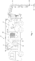
- FIG. 1 shown schematic representation illustrates in a simplified manner a suction dredge 01 according to the invention, which is operated in a suction mode.
- the indicated flow arrows indicate the resulting air flow on a Saugströmungsweg.
- the suction dredger 01 comprises a suction hose 02 with a suction mouth 03, into which sucked suction material 04 to be received in the suction mode is sucked.
- a suction air flow is generated by a fan unit 06, which flows starting at the suction mouth 03 via a separator 07, subsequently through a filter unit 08, towards the fan unit 06.
- Coarse and heavy components of the material are in the Separator 07 deposited while all the fine and light components are filtered out through the filter unit 08.
- the cleaned air is sucked into a suction side 09 in the fan unit 06, discharged at a pressure side 10, discharged to an exhaust port 11 and leaves the suction dredger there in the environment.
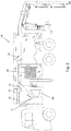
- Fig. 2 the suction dredge 01 is shown in a second operating state, namely in a so-called short-circuit mode, in which a short circuit between the suction side 09 and the pressure side 10 of the fan unit 06 is produced in order to circulate the air within the suction drier and thereby to heat it.
- the indicated flow arrows indicate the resulting air flow on a short circuit flow path.
- a Abluftstromweiche 12 is set so that the exhaust port 11 is completely closed and thus the entire exhaust air flow is fed into a return duct 13.
- the return passage 13 may include a plurality of flow regulating means 14 to supply the return air to various components and to heat them. In the example shown, the return air is fed to the separator 07.
- the flow-regulating means 14 may be open at an outlet directed into the filter unit 08, whereby the entire return air flow passes directly to the inlet of the filter unit 08.
- FIG. 3 the suction dredge 01 is shown in a third operating state, namely in a mulchblasmodus.
- the indicated flow arrows indicate the resulting air flow on a scaffoldblasweg.
- the exhaust air flow switch 12 is closed again.
- a secondary air opening 16 is opened, so that when the fan unit 06 is activated, secondary air 17 is drawn in from the environment.
- the secondary air opening 16 is arranged fluidically close to the suction side 09 of the fan unit, so that the flow resistance is lower than compared to the air path via the filter unit 08. This is scherche that secondary air is sucked, even if continue the guided over the return duct 13 return air through the filter unit is transported.
- the flow-regulating means 14 are partially opened in the blown-back mode in the illustrated embodiment. Return air is therefore directed into the separator 07. At the same time portions of the return air can be re-compressed and heated at a renewed passage of the fan 06. Due to the additionally sucked secondary air 17, the volume of air in the separator increases, so that there rises the pressure and heated return air is pressed into the suction hose 02 and there is guided to the suction orifice 03.
- the return air in remindblasmodus is not passed through the separator but from the return channel directly to the suction hose.
Landscapes
- Engineering & Computer Science (AREA)
- Civil Engineering (AREA)
- Structural Engineering (AREA)
- Mechanical Engineering (AREA)
- General Engineering & Computer Science (AREA)
- Mining & Mineral Resources (AREA)
- Architecture (AREA)
- Filtering Of Dispersed Particles In Gases (AREA)
- Jet Pumps And Other Pumps (AREA)
- Component Parts Of Construction Machinery (AREA)
- Earth Drilling (AREA)
Description
- Die Erfindung betrifft einen Saugbagger zur pneumatischen Aufnahme von festem oder flüssigem Sauggut mittels eines in einer Saugleitung schnell strömenden Saugluftstromes. Außerdem betrifft die Erfindung ein Verfahren zur Steuerung eines solchen Saugbaggers.
- Die
DE 38 24 710 C2 zeigt eine Vorrichtung, die sich zum Aufsaugen von körnigem Material vom Boden eignet, um dieses zu Reinigen. Von der Druckseite des den Saugluftstrom erzeugenden Gebläses wird ein Blasluftstrom abgezweigt, der über einen eigenständigen Kanal auf das am Boden liegende körnige Material gerichtet wird. - Aus der
DE 33 18 756 C2 ist eine Einrichtung bekannt zum Aufnehmen von Abfällen mittels eines Saugluftstroms, der durch ein Gebläse angefacht wird. Zur Ablösung der Abfälle vom Boden wird ein in einem getrennten Kanal rückgeführter Teil des vom Gebläse erzeugten Luftstroms als Blasstrom verwendet. DieEP 1 211 354 A2 beschreibt ein Verfahren zur Reinigung von Steinschuttgütern von leichten und feinteiligen Verschmutzungen. Dafür kommt ein Saugbagger zum Einsatz, der ein Saugrohr aufweist, welches über einen Kessel an eine Saugpumpe angeschlossen ist. Der Luftmengenstrom wird im Saugrohr so eingestellt, dass das Steinschüttgut in der Schwebe gehalten wird, während die leichteren Verschmutzungen abgesaugt werden. Durch zeitweise Verringerung des absaugenden Luftmengenstroms werden die gereinigten Steine dann wieder abgelegt. - Bei allen am Markt befindlichen Saugbaggern erzeugen Radialventilatoren große, sehr schnell strömende Luftströme, die ein aufzunehmendes Material (nachfolgend auch Sauggut genannt), welches sich im Bereich der Saugmündung eines Saugschlauches befindet, mit sich fortreißen. Der schnell strömende Saugluftstrom führt bei Temperaturen um den Gefrierpunkt aber zu einer schnellen Abkühlung der strömungstechnisch vor dem Ventilator angeordneten Komponenten des Saugbaggers. Bei niedrigen Temperaturen können die luftführenden Komponenten des Saugbaggers daher einfrieren. Außerdem kann feuchtes Sauggut beispielsweise im Saugschlauch oder im Abscheider anfrieren. Ebenso können die verwendeten Feinstfilter in der nachgeordneten Filteranlage zufrieren, was zu einer starken Verringerung des Saugluftstromes und somit der Förderleistung führt.
- Aus der
FR 2 286 772 - Die
DE 10 2010 060 973 A1 zeigt ein Steuerungsverfahren für ein Sauggebläse eines Saugbaggers, bei dem das Sauggebläse über einen Antriebsstrang von einem Verbrennungsmotor angetrieben wird. Das Sauggebläse ist eine Anordnung bestehend aus einem ersten und wenigstens einem weiteren Radialventilator. Zwischen der Saugleitung des ersten Ventilators und der Abluftleitung des weiteren Ventilators ist eine Bypassleitung angeordnet. In der Bypassleitung befindet sich eine eigen- oder fremdgesteuerte Bypassklappe, die im geöffneten Zustand eine teilweise Rückführung des geförderten Luftstroms ermöglicht und bei Normalbetrieb geschlossen ist. - Aus der
WO 2015/024558 A1 ist schließlich ein Saugbagger bekannt, der in bekannter Weise einen Saugschlauch mit einer Saugmündung zur pneumatischen Aufnahme von Sauggut mittels eines schnell strömenden Saugluftstromes umfasst. Weiterhin sind ein Abscheider zur Abscheidung des Sauggutes aus dem Luftstrom sowie eine Filteranlage zur Reinigung des Luftstromes vorgesehen. Ein Ventilator erzeugt den Saugluftstrom. Die Saugseite des Ventilators ist mit dem Ausgang der Filteranlage verbunden und die Druckseite ist an einen Abluftkanal angeschlossen. Der Abluftkanal mündet über eine Abluftöffnung in die Umgebung. Außerdem kann über einen Rückführkanal ein Anteil des Abluftstromes zu internen Komponenten des Saugbaggers geführt werden, u.a. zurück in den Abscheider, um dort das abgeschiedene Sauggut zu erwärmen. Ebenfalls erstreckt sich ein Abschnitt des Rückführkanals getrennt vom Saugschlauch bis in die Nähe der Saugmündung, um erwärmte Abluft dorthin zu führen. Ein verbleibender Nachteil dieses vorbekannten Saugbaggers besteht aber darin, dass zur Erwärmung des aufzunehmenden Sauggutes ein eigener Kanal bis zur Saugmündung geführt werden muss. Da der vom Ventilator erzeugbare Druck im Rückführkanal nicht hoch ist, muss dieser Kanal mit relativ großem Querschnitt bis zur Saugmündung geführt werden, was nicht nur die Kosten des Saugbaggers erhöht sondern vor allem die Handhabung des Saugschlauchs erschwert. Außerdem besteht weiterhin die Gefahr, dass das eingesaugte Sauggut im Saugschlauch wieder einfriert, wenn die Umgebungstemperaturen gering sind. - Eine Aufgabe der vorliegenden Erfindung ist ausgehend von der
WO 2015/024558 A1 darin zu sehen, einen weiter verbesserten Saugbagger bereitzustellen, bei dem das Einfrieren im Saugschlauch vermieden wird oder rückgängig gemacht werden kann, ohne dass dafür teure Heizelemente notwendig sind. Weiterhin wird angestrebt, dass auf das Anbringen eines sich bis zur Saugmündung erstreckenden getrennten Rückführkanals gänzlich verzichtet werden kann oder für diesen jedenfalls einen geringerer Querschnitt benötigt wird. Eine weitere Aufgabe besteht in der Angabe eines Verfahrens zur verbesserten Steuerung eines solchen Saugbaggers. - Diese Aufgabe wird zunächst durch einen Saugbagger gemäß dem beigefügten Anspruch 1 gelöst.
- Der erfindungsgemäße Saugbagger besitzt zunächst mindestens folgende Komponenten: Ein Saugschlauch mit einer Saugmündung dient der pneumatischen Aufnahme von festem oder flüssigem Sauggut, indem ein schnell strömender Saugluftstrom durch den Saugschlauch gezogen wird, welcher das Sauggut in der Nähe der Saugmündung mit sich reißt. Der Luftstrom mit dem aufgenommenen Sauggut wird einem Abscheider zugeführt, wo sich die Strömungsgeschwindigkeit aufgrund der Querschnittserweiterung im Strömungsweg drastisch verringert, um die groben und schweren Bestandteile des Sauggutes aus dem Luftstrom abzuscheiden und zu sammeln. Der Luftstrom wird dann einer Filtereinheit zugeführt, die in Strömungsrichtung hinter dem Abscheider liegt, zur Reinigung des Luftstromes. Die Filtereinheit setzt sich bevorzugt aus mehreren Filterstufen zusammen und ist an die gewöhnlich im Sauggut enthaltenen Bestandteile angepasst. Eine Ventilatoreinheit dient der Erzeugung des Luftstromes. Bevorzugt werden zwei oder mehr Radialventilatoren verwendet, die besonders bevorzugt strömungstechnisch hintereinander geschaltet sind, um einen starken Unterdruck und damit eine hohe Strömungsgeschwindigkeit im Saugluftstrom zu erzielen. Die Saugseite der Ventilatoreinheit kommuniziert mit dem Ausgang der Filteranlage und die Druckseite ist an einen Abluftkanal angeschlossen. Der Abluftkanal mündet an einer Abluftöffnung in die Umgebung, um jedenfalls im normalen Betriebszustand (Saugmodus) die Abluft nach außen abzugeben. Ein Rückführkanal ist über eine volumensteuerbare Rückführöffnung mit der Druckseite der Ventilatoreinheit, bevorzugt im Bereich des Abluftkanals, verbunden. Bevorzugt mündet der Rückführkanal in den Abscheider, um Anteile des Abluftstromes dorthin zurück zu führen. Über den Rückführkanal kann in abgewandelten Ausführungsformen erwärmte Abluft als Rückführluft auch an weitere Komponenten des Saugbaggers geführt werden.
- Die Erfindung zeichnet sich insbesondere dadurch aus, dass am Saugbagger eine volumensteuerbare Nebenluftöffnung vorgesehen ist, welche in Strömungsrichtung hinter der Filtereinheit die Zufuhr von Nebenluft aus der Umgebung zur Saugseite der Ventilatoreinheit gestattet. Damit kann von der Ventilatoreinheit auch dann zusätzliche Umgebungsluft über die Nebenluftöffnung angesaugt werden, wenn der Saugschlauch beispielsweise wegen Vereisung vollständig verschlossen sein sollte. Gleichzeitig lässt sich bei dem erfindungsgemäßen Saugbagger das Verhältnis zwischen über den Rückführkanal zurückgeführter Abluft (Rückführluft) und über die Abluftöffnung an die Umwelt abgegebener Abluft steuern, vorzugsweise durch Strömungsleitelemente, Drosselelemente oder dergleichen. Dadurch kann zunächst im Rückführkanal und, sofern dieser mit dem Abscheider strömungstechnisch verbunden wird, auch im Abscheider einen Überdruck erzeugt werden, indem die über die Nebenluftöffnung angesaugte Nebenluft vom Ventilator verdichtet und zurückgeführt wird. Diese Druckerhöhung kann letztlich zu einer Umkehr der Strömungsrichtung im Saugkanal genutzt werden, sodass Abluft durch den Saugschlauch bis zur Saugmündung geblasen wird. Im einfachsten Fall wird der Überdruck im Abscheider erzeugt, der unmittelbar mit dem Saugschlauch strömungstechnisch kommuniziert. In einer abgewandelten Ausführungsform kann der Rückführkanal auch über entsprechende strömungsleitende Mittel, beispielsweise Umleitklappen, an den Saugschlauch angeschlossen werden.
- Dabei ist festzuhalten, dass die vom Ventilator ggf. mehrfach umgewälzte Luftmenge durch den Energieeintrag erwärmt wird, sodass die im Rückführkanal bzw. im Abscheider mit Überdruck vorhandene Rückführluft eine deutlich höhere Temperatur als die Umgebungsluft hat (beispielsweise ca. 20 bis 40 K über der Umgebungsluft) und daher zum Erwärmen des Saugschlauchs bei niedrigen Außentemperaturen genutzt werden kann.
- Bevorzugt ist die Nebenluftöffnung mit einem regelbaren Nebenluftregelsystem ausgestattet, welches vorzugsweise als Nebenluftklappe ausgebildet ist, mittels derer ein gezieltes, regulierbares Beimischen von kalter Außenluft in den Luftstrom erfolgt. Durch das geregelte Ansaugen von kalter Außenluft ist es möglich die Temperatur der Luftströmung im Saugbagger zu regulieren und konstant zu halten. Dies ist insbesondere vorteilhaft, wenn ein strömungstechnischer Kurzschluss hergestellt wird, der hohe Temperaturen erzeugt.
- Gemäß einer bevorzugten Ausführungsform besitzt der Saugbagger weitere Luftführungskanäle und strömungsleitende Mittel, um die Wärmeenergie, die durch die Kompression der Luft beim Durchlaufen der Ventilatoreinheit eingetragen wird, zur Erwärmung der den Ventilatoren vorgelagerten Komponenten zu nutzen.
- Die Ventilatoreinheit ist vorzugsweise ein Radialventilator, ein Axialventilator oder ein Verdichter anderer Bauart. Besonders bevorzugt können mehrere gleichartige oder voneinander verschiedene Ventilatoren in Reihe oder parallel geschaltet sein.
- Bei einer bevorzugten Ausführung des Saugbaggers verläuft der Rückführkanal zum Abscheider, an welchen der Saugschlauch angeschlossen ist, um die Rückführluft auf diesem Weg in den Saugschlauch zu drücken.
- Bevorzugt beginnt der Rückführkanal vor dem Absperr- und/oder Umlenksystem für die Abluft und ist so gestaltet, dass die erwärmte Luft wahlweise zurück zu den, den Ventilatoren vorgelagerten Komponenten geleitet werden kann. Dazu sind strömungsregulierende Mittel im Rückführkanal vorgesehen, die den erwärmten Luftstrom freigeben oder sperren und gezielt einzelnen Komponenten zuführen können. Der Rückführkanal weist bevorzugt mehrere Ausgänge auf. Den Ausgängen sind strömungsleitende und/oder strömungssperrende Mittel (zusammenfassend als strömungsregulierende Mittel bezeichnet) zur Belüftung einer oder mehrerer Komponenten zugeordnet, sodass eine oder mehrere Komponenten gesteuert belüftet werden können. Der Rückführkanal kann verschiedene Querschnitte und Dimensionen aufweisen, die zudem entlang des Verlaufs des Rückführkanals verändert sein können. In weiteren Ausführungen kann der Rückführkanal auch geteilt ausgebildet sein sowie ganz oder bereichsweise aus mehreren Einzelkanälen bestehen.
- Eine besondere Ausführungsform des Saugbaggers gestattet den Betrieb in einem Kurzschlussmodus. Dabei wird mindestens die Abluftöffnung getrennt, d. h. die Abgabe von Abluft wird unterbrochen, sodass die vom Ventilator erzeugte Strömung nur innerhalb des Saugbaggers über die jeweils zugeschalteten Komponenten strömt. Im einfachsten Fall wird die Luft nur durch die Filtereinheit und den Ventilator gefördert, wobei es zu einer schnellen Erwärmung der Luft kommt, beispielsweise um gefrorene Filterabschnitte aufzutauen. In den Kurzschlussstrom kann bei Bedarf der Abscheider einbezogen werden, wenn dort Wärme benötigt wird. Eine Absperrung des Saugschlauchs ist dafür nicht notwendig (wenngleich möglich), da keine Ansaugung erfolgt, wenn die Luft nicht über die Abluftöffnung abgegeben werden kann.
- Die Menge der rückgeführten Luft ist über das gesteuerte Absperr- und/oder Umlenksystem für die Abluft des Ventilators regulierbar. Je nach Ansteuerungszustand des Absperr- und/oder Umlenksystem für die Abluft, in anderen Worten abhängig von der gewählten Stellung der strömungsregulierenden Mittel, ist es möglich, einen strömungstechnischen und somit auch thermischen Kurzschluss zu bewirken, sodass der genannte Kurzschlussmodus eingenommen wird.
- Um Beschädigungen des Saugbaggers durch zu hohe Temperaturen des Luftstromes zu vermeiden, ist das Absperr- und/oder Umlenksystem für die Abluft des Ventilators vorteilhaft unter Auswertung von Messwerten von Temperatursensoren steuerbar.
- Die Ausgänge des Rückführkanals können beispielsweise als Löcher oder Schlitze in einer Außenwand des Rückführkanals ausgebildet sein. Diesen Ausgängen ist jeweils ein strömungsregulierendes Mittel zugeordnet. Die Ansteuerung der strömungsregulierenden Mittel kann mechanisch, elektrisch, hydraulisch oder pneumatisch realisiert und durch eine Steuerung überwacht und ausgelöst sein. Eine Ansteuerung kann neben rechnergestützten oder regelkreisbasierten Ansteuerungen auch manuell möglich sein.
- In einer besonderen Ausführungsform kann eine Parallelluftleitung an den Rückführkanal angeschlossen sein, die parallel zum Saugschlauch geführt ist und in einem geringen Abstand zur Saugmündung endet. Der Abstand und die Ausrichtung des Ausgangs der Parallelluftleitung sind so gewählt, dass ein aus dem Ausgang austretender Anteil der in dem Rückführkanal geführten Rückführluft wenigstens anteilig wieder über die Saugmündung angesaugt und dem Saugbagger wieder zugeführt wird. Durch eine solche Gestaltung ist ein Anteil der warmen Rückführluft vor die Saugmündung leitbar und wird beim Betrieb des Saugbaggers zu einem großen Teil wieder in den Saugschlauch eingesogen. Um auf unterschiedliche Umgebungstemperaturen und Arbeitsbedingungen des Saugbaggers eingehen zu können, kann der Abstand des Ausgangs von der Saugmündung einstellbar sein.
- Die Erfindung stellt außerdem ein Verfahren zur Steuerung eines Saugbaggers gemäß dem beigefügten Anspruch 8 bereit.
- Das erfindungsgemäße Verfahren zeichnet sich zunächst dadurch aus, dass der Saugbagger in mindestens zwei verschiedene Betriebsmodi versetzt werden kann.
- In einem Saugmodus kommt es zur Aktivierung einer Ventilatoreinheit zur Erzeugung eines Luftstromes, und strömungsregulierende Mittel werden so eingestellt, dass der Luftstrom auf einem Saugströmungsweg verläuft. Der Saugströmungsweg beginnt an einer Saugmündung eines Saugschlauchs, um dort Sauggut aufzunehmen, verläuft zu einem Abscheider, wo der Großteil des Saugguts abgeschieden wird, dann weiter durch eine Filtereinheit, hin zur Ventilatoreinheit und von dort zu einer Abluftöffnung, um die gereinigte Abluft in die Umgebung abzugeben. Im Saugmodus ist die Abluftöffnung geöffnet, alle Rückleitungsklappen (die Bestandteil der strömungsregulierenden Mittel sind) sowie die Nebenluftklappe sind vorzugsweise vollständig geschlossen.
- In einem Rückblasmodus kommt es wiederum zur Aktivierung der Ventilatoreinheit zur Erzeugung des Luftstromes, und strömungsregulierende Mittel werden so eingestellt, dass der Luftstrom mindestens teilweise auf einem Rückblasweg verläuft. Der Rückblasweg beginnt an einer Nebenluftöffnung, an welcher Nebenluft aus der Umwelt angesaugt wird. Die Nebenluftöffnung ist dazu an einer Position angeordnet, in Strömungsrichtung vor der Saugseite des Ventilators und nach der Filtereinheit. Der Nebenluftweg verläuft weiter über die Ventilatoreinheit, in einen Rückführkanal bis hin zum Saugschlauch und dessen Saugmündung. Durch das Ansaugen von Nebenluft wird im Rückführkanal ein Überdruck erzeugt, ohne dass dafür die Rotationsrichtung der Ventilatoren geändert werden muss. Die durch die Ventilatoreinheit erwärmte, zurückgeführte Luft wird in den Saugschlauch gedrückt und transportiert dadurch bei Bedarf Wärme bis zur Saugmündung, ohne dass dafür ein separater Schlauch parallel zum Saugschlauch geführt werden muss.
- Gemäß einer bevorzugten Ausführungsform ermöglicht das Verfahren einen weiteren Betriebsmodus, einen Kurzschlussmodus. Im Kurzschlussmodus kommt es ebenfalls zur Aktivierung der Ventilatoreinheit zur Erzeugung des Luftstromes, und die strömungsregulierenden Mittel werden so eingestellt, dass der Luftstrom mindestens teilweise oder auch vollständig auf einem geschlossenen Kurzschlussströmungsweg verläuft. Der Kurzschlussströmungsweg verläuft mindestens durch die Filtereinheit hin zur Ventilatoreinheit und von dieser zurück zur Filtereinheit. Der Kurzschlussströmungsweg kann aber auch den Raum des Abscheiders und/oder weitere Kanäle oder Komponenten umfassen. Wesentlich ist dabei, dass keine Luft von außen zugeführt oder nach außen abgegeben wird. Dadurch kann die vom Ventilator eingebrachte Energie zu einer schnellen Erwärmung der umgewälzten Luft genutzt werden, insbesondere wenn einzelne Komponenten des Saugbaggers schnell erwärmt werden müssen.
- Der Kurzschlussmodus wird insbesondere benötigt, wenn ein Einfrieren von Komponenten droht oder eingetreten ist. In dieser Betriebsart ist die Abluftöffnung geschlossen sowie eine oder mehrere Rückleitungsklappen sind geöffnet, um den Rückführkanal freizugeben. Die Nebenluftklappe ist jedenfalls anfänglich ebenfalls geschlossen. Das im Fahrzeug befindliche Luftvolumen wird wiederholt durch die Ventilatoren gefördert und erhält bei jedem Durchgang einen Eintrag von Wärmeenergie in Form von Kompression. Dadurch steigt die Temperatur der Luft schnell an. Dieser Vorgang kann als Aufheizphase bezeichnet werden. In einer vorteilhaften Ausführungsform wird die erreichte Temperatur mittels Sensoren ständig kontrolliert.
- Der oben genannte Rückblasmodus wird bevorzugt ausgehend vom Kurzschlussmodus aktiviert. Beim Erreichen einer vorgegebenen Maximaltemperatur kann dazu die Nebenluftöffnung, welche bevorzugt nahe der Saugseite der Ventilatoren montiert ist, geöffnet werden. In diesem Zustand ist der Strömungswiderstand über die Nebenluftöffnung geringer als der Umwälzwiderstand des internen Luftvolumens des Saugbaggers. Zusätzlich zum Umwälzen des inneren Luftvolumens wird somit eine zusätzliche Menge Umgebungsluft angesaugt. Diese Umgebungsluft mischt sich mit dem umlaufenden, heißen Kurzschlussluftstrom. Da die Abluftöffnung geschlossen ist und sich das interne Luftvolumen nicht ändert, wird der Rückführluftstrom in die Saugleitung transportiert.
- Gemäß einer bevorzugten Ausführungsform kann außerdem ein Saugmodus mit Aufheizfunktion gewählt werden. Dieser gestattet einen leistungsreduzierten Saugbetrieb und gleichzeitiges Aufheizen der internen Komponenten. Aufgrund der leistungsfähigen Ventilatoreinheit werden im normalen Saugmodus (siehe oben) Luftgeschwindigkeiten im Saugschlauch bzw. an der Saugmündung erreicht, die in vielen Anwendungsfällen deutlich über dem zum Transport des Sauggutes notwendigen Wert liegen. Im Saugmodus mit Aufheizfunktion wird bei konstanter Ventilatorenleistung die Luftmenge und somit auch die Luftgeschwindigkeit im Saugschlauch auf ein zum Transport des Sauggutes noch ausreichendes Maß verkleinert. Das Differenzvolumen, welches sich aus der Ventilatorenvolumenleistung abzüglich des minimierten Luftstromvolumens im Saugschlauch ergibt, wird durch Umwälzen von Luft innerhalb des Saugbaggers beigesteuert. Das umgewälzte Luftvolumen strömt dabei entlang des oben beschriebenen Kurzschlussweges, sodass es zum verstärkten Aufheizen des Gesamtvolumenstroms kommt.
- Im Saugmodus mit Aufheizfunktion sind anfänglich die Abluftöffnung sowie die Nebenluftöffnung verschlossen, die Absperrmittel im Rückführkanal (Bestandteil der strömungsregulierenden Mittel) sind teilweise oder ganz geöffnet. Wird jetzt der Ventilator gestartet, entspricht dies zunächst dem Kurzschlussmodus. Wird jetzt die Abluftöffnung teilweise geöffnet, kann je nach Öffnungsgrad ein Teil des Saugluftstromes, der beim Durchlaufen durch die Ventilatoren erwärmt wurde, an die Umwelt gelangen. Da sich das interne Luftvolumen und die Förderleistung der Ventilatoren nicht verändern, wird die gleiche Menge dieses Luftstromes über den Saugschlauch nachgesaugt. Die Menge des an der Saugmündung resultierenden Saugluftstromes wird also über den Volumenstrom an der Abluftöffnung reguliert. Bei entsprechender Einstellung ist dieser leistungsreduzierte Saugluftstrom in der Lage, Material, welches sich im Bereich der Saugmündung befindet mitzureißen. Im Inneren des Saugbaggers erfolgt eine Durchmischung der angesaugten, kalten Außenluft und der Luft, die im Umluftbetrieb ständig aufgeheizt wird. Somit wird ein Einfrieren der inneren Komponenten des Saugbaggers im Saugbetrieb verhindert. Es ist darauf hinzuweisen, dass der Saugmodus mit Aufheizfunktion ohne über die Nebenluftöffnung angesaugte Nebenluft auskommt, sodass dieser Betriebsmodus auch bei Saugbaggern angewendet werden kann, die keine Nebenluftöffnung besitzen.
- Weiter Vorteile und Einzelheiten der Erfindung ergeben sich aus der nachfolgenden Beschreibung einer bevorzugten Ausführungsform, unter Bezugnahme auf die Zeichnung. Es zeigen:
- Fig. 1
- eine Prinzipdarstellung einer Ausführungsform eines erfindungsgemäßen Saugbaggers im Saugmodus;
- Fig. 2
- eine Prinzipdarstellung des Saugbaggers im Kurzschlussmodus;
- Fig. 3
- eine Prinzipdarstellung des Saugbaggers im Rückblasmodus.
- Die in
Fig. 1 gezeigte Prinzipdarstellung verdeutlicht in vereinfachter Weise einen erfindungsgemäßen Saugbagger 01, der in einem Saugmodus betrieben wird. Die eingezeichneten Strömungspfeile zeigen die resultierende Luftströmung auf einem Saugströmungsweg an. Der Saugbagger 01 umfasst einen Saugschlauch 02 mit einer Saugmündung 03, in welche im Saugmodus aufzunehmendes Sauggut 04 eingesaugt wird. Dazu wird von einer Ventilatoreinheit 06 ein Saugluftstrom erzeugt, der beginnend an der Saugmündung 03 über einen Abscheider 07, nachfolgend durch eine Filtereinheit 08, hin zur Ventilatoreinheit 06 strömt. Grobe und schwere Bestandteile des Sauggutes werden im Abscheider 07 abgeschieden, während alle feinen und leichten Bestandteile durch die Filtereinheit 08 herausgefiltert werden. Die gereinigte Luft wird an einer Saugseite 09 in die Ventilatoreinheit 06 eingesaugt, an einer Druckseite 10 ausgegeben, zu einer Abluftöffnung 11 abgegeben und verlässt den Saugbagger dort in die Umwelt. - In
Fig. 2 ist der Saugbagger 01 in einem zweiten Betriebszustand gezeigt, nämlich in einem sogenannten Kurzschlussmodus, bei welchem strömungstechnisch ein Kurzschluss zwischen der Saugseite 09 und der Druckseite 10 der Ventilatoreinheit 06 hergestellt ist, um die Luft innerhalb des Saugbaggers umzuwälzen und dadurch zu erwärmen. Die eingezeichneten Strömungspfeile zeigen die resultierende Luftströmung auf einem Kurzschlussströmungsweg an. Dazu ist eine Abluftstromweiche 12 so eingestellt, dass die Abluftöffnung 11 vollständig verschlossen ist und somit der gesamte Abluftstrom in einen Rückführkanal 13 eingespeist wird. Der Rückführkanal 13 kann mehrere strömungsregulierende Mittel 14 umfassen, um die Rückführluft verschiedenen Komponenten zuzuführen und diese zu erwärmen. Im dargestellten Beispiel wird die Rückführluft dem Abscheider 07 zugeführt. Durch eine derartige Führung des Rückführluftstroms werden zumindest das in dem Abscheider zuoberst liegende Sauggut, der Abscheider 07, die aus dem Abscheider zur Filtereinheit 08 führenden Luftkanäle sowie die Filtereinheit 08 selbst angewärmt. Der in den Abscheider 07 gerichtete Rückführluftstrom wird erneut durch die Ventilatoreinheit 06 angesaugt, komprimiert, damit weiter erwärmt und gelangt wiederum über den Rückführkanal 13 in den Abscheider 07. Da der Luftstrom bei jedem Durchlauf durch den Ventilator 06 weiter erwärmt wird, bewirkt dieser Betriebsmodus ein sehr schnelles Aufheizen der von dem Luftstrom durchflossenen Komponenten. - In abgewandelten Ausführungen kann das strömungsregulierende Mittel 14 an einem in die Filtereinheit 08 gerichteten Ausgang geöffnet sein, wodurch der gesamte Rückführluftstrom direkt zum Eingang der Filtereinheit 08 gelangt.
- In
Fig. 3 ist der Saugbagger 01 in einem dritten Betriebszustand gezeigt, nämlich in einem Rückblasmodus. Die eingezeichneten Strömungspfeile zeigen die resultierende Luftströmung auf einem Rückblasweg an. Dazu ist die Abluftstromweiche 12 wiederum geschlossen. Eine Nebenluftöffnung 16 ist geöffnet, sodass bei aktivierter Ventilatoreinheit 06 Nebenluft 17 aus der Umwelt angesaugt wird. Die Nebenluftöffnung 16 ist strömungstechnisch nahe an der Saugseite 09 der Ventilatoreinheit angeordnet, sodass der Strömungswiderstand geringer ist als gegenüber dem Luftweg über die Filtereinheit 08. Dadurch ist schergestellt, dass Nebenluft angesaugt wird, selbst wenn weiterhin die über den Rückführkanal 13 geführte Rückführluft durch die Filtereinheit transportiert wird. Die strömungsregulierenden Mittel 14 sind im Rückblasmodus bei der dargestellten Ausführungsform teilweise geöffnet. Rückführluft wird daher in den Abscheider 07 gelenkt. Gleichzeitig können Anteile der Rückführluft bei einer erneuten Passage des Ventilators 06 erneut komprimiert und erwärmt werden. Aufgrund der zusätzlich angesaugten Nebenluft 17 erhöht sich das Luftvolumen im Abscheider, sodass dort der Druck steigt und erwärmte Rückführluft in den Saugschlauch 02 gedrückt und dort bis zur Saugmündung 03 geführt wird. - Bei einer abgewandelten Ausführungsform wird die Rückführluft im Rückblasmodus nicht über den Abscheider sondern vom Rückführkanal direkt zum Saugschlauch geführt.
-
- 01
- - Saugbagger
- 02
- - Saugschlauch
- 03
- - Saugmündung
- 04
- - Sauggut
- 05
- -
- 06
- - Ventilatoreinheit
- 07
- - Abscheider
- 08
- - Filtereinheit
- 09
- - Saugseite
- 10
- - Druckseite
- 11
- - Abluftöffnung
- 12
- - Abluftstromweiche
- 13
- - Rückführkanal
- 14
- - strömungsregulierenden Mittel
- 15
- -
- 16
- - Nebenluftöffnung
- 17
- - Nebenluft
Claims (10)
- Saugbagger (01) umfassend:- einen Saugschlauch (02) mit einer Saugmündung (03), zur pneumatischen Aufnahme von festem oder flüssigem Sauggut (04) mittels eines schnell strömenden Luftstromes;- einen Abscheider (07) zur Abscheidung des Sauggutes (04) aus dem Luftstrom;- eine Filtereinheit (08), die in Strömungsrichtung hinter dem Abscheider (07) liegt, zur Reinigung des Luftstromes;- eine Ventilatoreinheit (06) zur Erzeugung des Luftstromes, deren Saugseite (09) mit dem Ausgang der Filtereinheit (08) verbunden ist und deren Druckseite (10) an eine in die Umgebung zu öffnende Abluftöffnung (11) angeschlossen ist;- einen Rückführkanal (13), der volumensteuerbar mit der Druckseite (10) der Ventilatoreinheit (06) verbindbar ist;dadurch gekennzeichnet, dass eine volumensteuerbare Nebenluftöffnung (16) vorgesehen ist, welche in Strömungsrichtung hinter der Filtereinheit (08) die Zufuhr von Nebenluft (17) aus der Umgebung zur Saugseite (09) der Ventilatoreinheit (06) ermöglicht, dass der Rückführkanal (13) strömungstechnisch an den Saugschlauch (02) koppelbar ist, und dass der Anteil der über den Rückführkanal (13) geführten Rückführluft steuerbar ist, um im Rückführkanal (13) einen Überdruck zu erzeugen, der zum Ausblasen von Rückführluft durch den Saugschlauch (02) führt.
- Saugbagger (01) nach Anspruch 1, dadurch gekennzeichnet, dass die Ventilatoreinheit (06) mindestens zwei strömungstechnisch in Reihe geschaltete Ventilatoren umfasst.
- Saugbagger (01) nach Anspruch 1 oder 2, dadurch gekennzeichnet, dass die Nebenluftöffnung (16) in einen Strömungsabschnitt mündet, der sich zwischen der Filtereinheit (08) und der Saugseite (09) der Ventilatoreinheit (06) erstreckt, und dass sie eine verstellbare Öffnungsklappe umfasst, zur Veränderung des lichten Öffnungsquerschnitts zwischen einer geschlossenen Position und einer maximal geöffneten Position.
- Saugbagger (01) nach einem der Ansprüche 1 bis 3, dadurch gekennzeichnet, dass der Rückführkanal (13) über ein strömungsregulierendes Mittel zusätzlich an eine Parallelluftleitung angeschlossen ist, die in der Nähe der Saugmündung (03) endet, um dort erwärmte Rückführluft abzugeben.
- Saugbagger (01) nach einem der Ansprüche 1 bis 4, dadurch gekennzeichnet, dass Absperrmittel vorhanden sind, welche mindestens die Abluftöffnung (11) sowie ggf. auch den Saugschlauch (02), die Parallelluftleitung und den Abscheider (07) strömungstechnisch absperren, sodass bei aktivierter Ventilatoreinheit (06) die Luft durch die Filtereinheit (08) und die Ventilatoreinheit (06) umgewälzt wird, um diese zu erwärmen.
- Saugbagger (01) nach einem der Ansprüche 1 bis 5, dadurch gekennzeichnet, das ein oder mehrere Temperatursensoren angeordnet sind, um die Temperatur von Komponenten zu bestimmen und diese an eine Steuereinheit zu liefern, welche den Betriebsmodus und die Volumensteuerung der verschiedenen Luftströme steuert.
- Saugbagger (01) nach einem der Ansprüche 1 bis 6, dadurch gekennzeichnet, dass der Rückführkanal (13) über strömungsregulierende Mittel (14) mit dem Abscheider (07) koppelbar ist, sodass der Rückführkanal (13) strömungstechnisch über den Abscheider (07) mit dem Saugschlauch (02) verbunden ist.
- Verfahren zur Steuerung eines Saubaggers (01), das folgende Schritte umfasst:- Wählen eines Betriebsmodus aus einer Gruppe von Betriebsmodi, welche mindestens einen Saugmodus und einen Rückblasmodus umfasst,wobei im Saugmodus folgende Schritte ausgeführt werden:- Aktivierung einer Ventilatoreinheit (06) zur Erzeugung eines Luftstromes;- Einstellen von strömungsregulierenden Mitteln (12, 14), sodass der Luftstrom auf einem Saugströmungsweg verläuft, beginnend an einer Saugmündung (03) eines Saugschlauchs (02), in einen Abscheider (07), nachfolgend durch eine Filtereinheit (08), hin zur Ventilatoreinheit (06) und von dort über eine Abluftöffnung (11) in die Umgebung;und wobei im Rückblasmodus folgende Schritte ausgeführt werden:- Aktivierung der Ventilatoreinheit (06) zur Erzeugung des Luftstromes;- Einstellen der strömungsregulierenden Mittel (12, 14), sodass der Luftstrom mindestens teilweise auf einem Rückblasweg verläuft, beginnend an einer Nebenluftöffnung (16), über die Ventilatoreinheit (06), in einen Rückführkanal (13) hin zum Saugschlauch (02) und durch diesen Saugschlauch (02) bis zu dessen Saugmündung (03).
- Verfahren nach Anspruch 8, dadurch gekennzeichnet, dass die Gruppe von Betriebsmodi weiterhin einen Kurzschlussmodus umfasst, in welchem folgende Schritte ausgeführt werden:- Aktivierung der Ventilatoreinheit (06) zur Erzeugung des Luftstromes;- Einstellen der strömungsregulierenden Mittel (12, 14), sodass der Luftstrom mindestens teilweise auf einem geschlossenen Kurzschlussströmungsweg verläuft, welcher mindestens durch die Filtereinheit (08) hin zur Ventilatoreinheit (06) und von dieser zurück zur Filtereinheit (08) verläuft, wobei keine Luft von außen zugeführt und keine Luft nach außen abgegeben wird.
- Verfahren nach Anspruch 9, dadurch gekennzeichnet, dass die Gruppe von Betriebsmodi weiterhin einen Saugmodus mit Aufheizfunktion umfasst, in welchem folgende Schritte ausgeführt werden:- Aktivierung der Ventilatoreinheit (06) zur Erzeugung eines Luftstromes;- Einstellen von strömungsregulierenden Mitteln (12, 14), sodass der Luftstrom teilweise auf dem Saugströmungsweg und teilweise auf dem Kurzschlussströmungsweg verläuft.
Applications Claiming Priority (2)
| Application Number | Priority Date | Filing Date | Title |
|---|---|---|---|
| DE102015105836.7A DE102015105836B3 (de) | 2015-04-16 | 2015-04-16 | Saugbagger mit Strömungsumkehr sowie Verfahren zu dessen Steuerung |
| PCT/EP2016/057710 WO2016166021A1 (de) | 2015-04-16 | 2016-04-08 | Saugbagger mit strömungsumkehr sowie verfahren zu dessen steuerung |
Publications (2)
| Publication Number | Publication Date |
|---|---|
| EP3283695A1 EP3283695A1 (de) | 2018-02-21 |
| EP3283695B1 true EP3283695B1 (de) | 2019-01-30 |
Family
ID=55358727
Family Applications (1)
| Application Number | Title | Priority Date | Filing Date |
|---|---|---|---|
| EP16717865.6A Active EP3283695B1 (de) | 2015-04-16 | 2016-04-08 | Saugbagger mit strömungsumkehr sowie verfahren zu dessen steuerung |
Country Status (6)
| Country | Link |
|---|---|
| US (1) | US10640938B2 (de) |
| EP (1) | EP3283695B1 (de) |
| CN (1) | CN107532404B (de) |
| CA (1) | CA2982509C (de) |
| DE (1) | DE102015105836B3 (de) |
| WO (1) | WO2016166021A1 (de) |
Cited By (1)
| Publication number | Priority date | Publication date | Assignee | Title |
|---|---|---|---|---|
| EP4764085A2 (de) | 2021-04-09 | 2026-06-24 | Armin Mörtlbauer | Saugvorrichtung zum trennen von bauschutt und baumaschine mit einer derartigen saugvorrichtung |
Families Citing this family (12)
| Publication number | Priority date | Publication date | Assignee | Title |
|---|---|---|---|---|
| CA2943723C (en) * | 2015-10-02 | 2021-09-07 | Wausau Equipment Company, Inc. | Cold air blower with self-supported boom |
| DE102016106427B3 (de) * | 2016-04-08 | 2017-03-23 | Reschwitzer Saugbagger Produktions Gmbh | Verfahren zur Steuerung der Bewegung eines Gelenkschlauchträgers eines Saugbaggers |
| DE202017100264U1 (de) | 2017-01-19 | 2017-03-22 | Reschwitzer Saugbagger Produktions Gmbh | Vorrichtung zur Aufnahme und zum Transport von Bauteilen, insbesondere Schläuchen oder Rohren, Materialsammelbehälter für ein Fahrzeug sowie Saugbagger mit einer solchen Vorrichtung |
| DE102017108731B4 (de) * | 2017-04-24 | 2021-06-24 | Reschwitzer Saugbagger Produktions Gmbh | Saugbagger mit schwenkbarer Filtereinheit |
| FR3065975B1 (fr) * | 2017-05-03 | 2019-04-26 | Lomaroute | Bras d'aspiration articule d'une excavatrice aspiratrice, muni d'une buse inclinable |
| CN108097663A (zh) * | 2017-12-19 | 2018-06-01 | 潘桂丰 | 一种用于废旧高压继电器的除尘装置 |
| DE102018104491A1 (de) * | 2018-02-27 | 2019-08-29 | Putzmeister Engineering Gmbh | Großmanipulator mit Schwingungsdämpfer |
| CN108824533A (zh) * | 2018-07-10 | 2018-11-16 | 长葛市水利工程技术推广中心 | 一种水利工程用高效清淤装置 |
| DE102019127258A1 (de) | 2019-10-10 | 2021-04-15 | Zenner Ventilatoren Gmbh | Verfahren zur Beeinflussung eines durch einen Ventilator erzeugten Saug- oder Druckstromes und Anordnung zur Durchführung des Verfahrens |
| CN111677031A (zh) * | 2020-05-08 | 2020-09-18 | 武汉永清环保科技工程有限公司 | 一种智慧湖泊湖底沉积物清理设备及其工艺 |
| ES3029078T3 (en) * | 2022-02-04 | 2025-06-23 | Mathieu | Vehicle for cleaning road surfaces |
| IT202300026046A1 (it) | 2023-12-06 | 2025-06-06 | Longo Euroservice S R L | Automezzo per l’aspirazione di materiale secco e/o liquido |
Family Cites Families (17)
| Publication number | Priority date | Publication date | Assignee | Title |
|---|---|---|---|---|
| GB1398983A (en) * | 1972-05-18 | 1975-06-25 | British Gas Corp | Excavating machines |
| US3842461A (en) * | 1973-05-15 | 1974-10-22 | Walkee Vacuum Services Ltd | Industrial vacuum apparatus |
| FR2286772A1 (fr) * | 1974-10-03 | 1976-04-30 | Etpm | Installation de manutention pneumatique |
| DE3318756C2 (de) | 1983-05-24 | 1994-12-08 | Schneider Walter Gmbh Co Kg | Fahrbare Einrichtung zum Aufnehmen von Abfällen, insbesondere aus Schotterbetten einer Gleisanlage |
| DE3824710A1 (de) * | 1988-07-20 | 1990-01-25 | Edelhoff Polytechnik | Verfahren und vorrichtung zum reinigen von mit koernigem material bestreuten boeden von staub und schmutz |
| US5016717A (en) * | 1989-03-14 | 1991-05-21 | Aqua-Vac Locators, Inc. | Vacuum excavator |
| DE4306135A1 (de) * | 1993-02-27 | 1994-09-01 | Vmb Vesta Maschbau Gmbh & Co | Saugbagger |
| DE19718868A1 (de) * | 1997-05-03 | 1998-11-05 | Rinker Karl Dipl Ing Fh | Saugbagger |
| DE10059729A1 (de) * | 2000-11-30 | 2002-06-13 | Stefan Mattes | Verfahren zur Reinigung von Steinschüttungen |
| JP2007291747A (ja) * | 2006-04-26 | 2007-11-08 | Kazuyuki Igarashi | アスベストの回収・分離・濾過方法及びそのための装置 |
| CN201027321Y (zh) * | 2007-04-12 | 2008-02-27 | 广州普得环保设备有限公司 | 一种新型多功能清淤车 |
| CN201195853Y (zh) * | 2008-03-03 | 2009-02-18 | 管焕钦 | 移动式水底淤泥抽吸输送装置 |
| CN101618916B (zh) * | 2008-07-02 | 2012-07-04 | 云南易龙机械有限公司 | 污水复清方法及设备 |
| JP2011083759A (ja) * | 2009-10-14 | 2011-04-28 | Kazumasa Onishi | 太陽電池用シリコンの製造に適するろ過装置及びろ過方法 |
| DE102010060973B4 (de) * | 2010-12-02 | 2016-02-11 | Zenner Ventilatoren Gmbh | Steuerungsverfahren für das Sauggebläse eines Saugbaggers |
| KR101392146B1 (ko) * | 2011-08-08 | 2014-05-28 | 엔비텍 주식회사 | 수륙양용 수 처리장치 |
| DE102013109074A1 (de) * | 2013-08-22 | 2015-02-26 | Reschwitzer Saugbagger Produktions Gmbh | Saugbagger zur pneumatischen Aufnahme von Sauggut |
-
2015
- 2015-04-16 DE DE102015105836.7A patent/DE102015105836B3/de not_active Expired - Fee Related
-
2016
- 2016-04-08 CA CA2982509A patent/CA2982509C/en active Active
- 2016-04-08 WO PCT/EP2016/057710 patent/WO2016166021A1/de not_active Ceased
- 2016-04-08 US US15/565,990 patent/US10640938B2/en active Active
- 2016-04-08 EP EP16717865.6A patent/EP3283695B1/de active Active
- 2016-04-08 CN CN201680021436.6A patent/CN107532404B/zh active Active
Non-Patent Citations (1)
| Title |
|---|
| None * |
Cited By (1)
| Publication number | Priority date | Publication date | Assignee | Title |
|---|---|---|---|---|
| EP4764085A2 (de) | 2021-04-09 | 2026-06-24 | Armin Mörtlbauer | Saugvorrichtung zum trennen von bauschutt und baumaschine mit einer derartigen saugvorrichtung |
Also Published As
| Publication number | Publication date |
|---|---|
| WO2016166021A1 (de) | 2016-10-20 |
| CN107532404A (zh) | 2018-01-02 |
| CA2982509A1 (en) | 2016-10-20 |
| US20180119375A1 (en) | 2018-05-03 |
| CN107532404B (zh) | 2021-05-04 |
| EP3283695A1 (de) | 2018-02-21 |
| US10640938B2 (en) | 2020-05-05 |
| DE102015105836B3 (de) | 2016-03-10 |
| CA2982509C (en) | 2023-09-19 |
Similar Documents
| Publication | Publication Date | Title |
|---|---|---|
| DE102015105836B3 (de) | Saugbagger mit Strömungsumkehr sowie Verfahren zu dessen Steuerung | |
| DE102008020310B4 (de) | Kraftfahrzeug mit zwei Wärmetauschern | |
| EP2555978B1 (de) | Kompressor/turbinen-anordnung, klimaaggregat und verfahren zum betreiben einer kompressor/turbinen-anordnung | |
| EP2576252B1 (de) | Temperiervorrichtung und verfahren zur erzeugung eines temperierten luftstroms | |
| EP1880939A1 (de) | Flugzeugklimaanlage und Verfahren zum Betreiben einer Flugzeugklimaanlage | |
| DE102018113185B4 (de) | Brennstoffzellenfahrzeug mit führungsabschnitt zum führen von abgas und steuerverfahren für dieses brennstoffzellenfahrzeug | |
| EP3657584A1 (de) | Kühl- und gasentfeuchtungssystem, transportmittel und verfahren zum betreiben eines kühl- und gasentfeuchtungssystems | |
| DE202010011137U1 (de) | Klimatisierungseinrichtung mit Luftkonditionierungseinrichtung | |
| WO2015024558A1 (de) | Saugbagger zur pneumatischen aufnahme von sauggut | |
| DE19641467A1 (de) | Sekundärluftsystem | |
| DE29500781U1 (de) | Vorrichtung zum Kühlen von Gasen | |
| DE1530877A1 (de) | Kraftfahrzeug mit einer die Temperatur im Inneren des Fahrgastraumes regelnden Anlage | |
| EP3564127A1 (de) | Flugzeugkühlsystem und flugzeug mit flugzeugkühlsystem | |
| EP2792882B1 (de) | Luftpresser für eine Druckluftanlage, insbesondere für eine Druckluftbremsanlage eines Nutzfahrzeugs | |
| DE112011100614T5 (de) | Anordnung zum Enteisen eines Ladeluftkühlers | |
| DE102020007164A1 (de) | Klimaanlage für einen Wärmepumpenbetrieb | |
| EP1262645B1 (de) | Selbstfahrende Erntemaschine | |
| DE102008021761A1 (de) | Verfahren zum Betreiben einer Anordnung von Wärmetauschern und hierfür geeignete Vorrichtung | |
| DE102014004664B4 (de) | Verfahren zur Reinigung einer Filtereinrichtung in einem Frischluftsystem | |
| EP1382512A2 (de) | Luftleitanordnung für den Unterbereich eines Fahrzeuges | |
| WO2018010971A1 (de) | Lüftungsanordnung mit einer dunstabzugshaube | |
| EP0728078A1 (de) | Kraftfahrzeug-klimaanlage | |
| DE202013011876U1 (de) | Saugbagger zur pneumatischen Aufnahme von Sauggut | |
| WO2018024584A1 (de) | Klimatisierungsvorrichtung für ein kraftfahrzeug und verfahren zu deren betrieb | |
| EP4542729B1 (de) | Batteriesystem |
Legal Events
| Date | Code | Title | Description |
|---|---|---|---|
| STAA | Information on the status of an ep patent application or granted ep patent |
Free format text: STATUS: THE INTERNATIONAL PUBLICATION HAS BEEN MADE |
|
| PUAI | Public reference made under article 153(3) epc to a published international application that has entered the european phase |
Free format text: ORIGINAL CODE: 0009012 |
|
| STAA | Information on the status of an ep patent application or granted ep patent |
Free format text: STATUS: REQUEST FOR EXAMINATION WAS MADE |
|
| 17P | Request for examination filed |
Effective date: 20171116 |
|
| AK | Designated contracting states |
Kind code of ref document: A1 Designated state(s): AL AT BE BG CH CY CZ DE DK EE ES FI FR GB GR HR HU IE IS IT LI LT LU LV MC MK MT NL NO PL PT RO RS SE SI SK SM TR |
|
| AX | Request for extension of the european patent |
Extension state: BA ME |
|
| DAV | Request for validation of the european patent (deleted) | ||
| DAX | Request for extension of the european patent (deleted) | ||
| GRAP | Despatch of communication of intention to grant a patent |
Free format text: ORIGINAL CODE: EPIDOSNIGR1 |
|
| STAA | Information on the status of an ep patent application or granted ep patent |
Free format text: STATUS: GRANT OF PATENT IS INTENDED |
|
| INTG | Intention to grant announced |
Effective date: 20181024 |
|
| GRAS | Grant fee paid |
Free format text: ORIGINAL CODE: EPIDOSNIGR3 |
|
| GRAA | (expected) grant |
Free format text: ORIGINAL CODE: 0009210 |
|
| STAA | Information on the status of an ep patent application or granted ep patent |
Free format text: STATUS: THE PATENT HAS BEEN GRANTED |
|
| RAP1 | Party data changed (applicant data changed or rights of an application transferred) |
Owner name: RSP GMBH |
|
| AK | Designated contracting states |
Kind code of ref document: B1 Designated state(s): AL AT BE BG CH CY CZ DE DK EE ES FI FR GB GR HR HU IE IS IT LI LT LU LV MC MK MT NL NO PL PT RO RS SE SI SK SM TR |
|
| REG | Reference to a national code |
Ref country code: GB Ref legal event code: FG4D Free format text: NOT ENGLISH |
|
| REG | Reference to a national code |
Ref country code: CH Ref legal event code: EP |
|
| REG | Reference to a national code |
Ref country code: AT Ref legal event code: REF Ref document number: 1093382 Country of ref document: AT Kind code of ref document: T Effective date: 20190215 |
|
| REG | Reference to a national code |
Ref country code: IE Ref legal event code: FG4D Free format text: LANGUAGE OF EP DOCUMENT: GERMAN |
|
| REG | Reference to a national code |
Ref country code: DE Ref legal event code: R096 Ref document number: 502016003296 Country of ref document: DE |
|
| REG | Reference to a national code |
Ref country code: NL Ref legal event code: FP |
|
| REG | Reference to a national code |
Ref country code: LT Ref legal event code: MG4D |
|
| PG25 | Lapsed in a contracting state [announced via postgrant information from national office to epo] |
Ref country code: PL Free format text: LAPSE BECAUSE OF FAILURE TO SUBMIT A TRANSLATION OF THE DESCRIPTION OR TO PAY THE FEE WITHIN THE PRESCRIBED TIME-LIMIT Effective date: 20190130 Ref country code: LT Free format text: LAPSE BECAUSE OF FAILURE TO SUBMIT A TRANSLATION OF THE DESCRIPTION OR TO PAY THE FEE WITHIN THE PRESCRIBED TIME-LIMIT Effective date: 20190130 Ref country code: ES Free format text: LAPSE BECAUSE OF FAILURE TO SUBMIT A TRANSLATION OF THE DESCRIPTION OR TO PAY THE FEE WITHIN THE PRESCRIBED TIME-LIMIT Effective date: 20190130 Ref country code: PT Free format text: LAPSE BECAUSE OF FAILURE TO SUBMIT A TRANSLATION OF THE DESCRIPTION OR TO PAY THE FEE WITHIN THE PRESCRIBED TIME-LIMIT Effective date: 20190530 Ref country code: FI Free format text: LAPSE BECAUSE OF FAILURE TO SUBMIT A TRANSLATION OF THE DESCRIPTION OR TO PAY THE FEE WITHIN THE PRESCRIBED TIME-LIMIT Effective date: 20190130 Ref country code: SE Free format text: LAPSE BECAUSE OF FAILURE TO SUBMIT A TRANSLATION OF THE DESCRIPTION OR TO PAY THE FEE WITHIN THE PRESCRIBED TIME-LIMIT Effective date: 20190130 Ref country code: NO Free format text: LAPSE BECAUSE OF FAILURE TO SUBMIT A TRANSLATION OF THE DESCRIPTION OR TO PAY THE FEE WITHIN THE PRESCRIBED TIME-LIMIT Effective date: 20190430 |
|
| PG25 | Lapsed in a contracting state [announced via postgrant information from national office to epo] |
Ref country code: GR Free format text: LAPSE BECAUSE OF FAILURE TO SUBMIT A TRANSLATION OF THE DESCRIPTION OR TO PAY THE FEE WITHIN THE PRESCRIBED TIME-LIMIT Effective date: 20190501 Ref country code: LV Free format text: LAPSE BECAUSE OF FAILURE TO SUBMIT A TRANSLATION OF THE DESCRIPTION OR TO PAY THE FEE WITHIN THE PRESCRIBED TIME-LIMIT Effective date: 20190130 Ref country code: IS Free format text: LAPSE BECAUSE OF FAILURE TO SUBMIT A TRANSLATION OF THE DESCRIPTION OR TO PAY THE FEE WITHIN THE PRESCRIBED TIME-LIMIT Effective date: 20190530 Ref country code: HR Free format text: LAPSE BECAUSE OF FAILURE TO SUBMIT A TRANSLATION OF THE DESCRIPTION OR TO PAY THE FEE WITHIN THE PRESCRIBED TIME-LIMIT Effective date: 20190130 Ref country code: RS Free format text: LAPSE BECAUSE OF FAILURE TO SUBMIT A TRANSLATION OF THE DESCRIPTION OR TO PAY THE FEE WITHIN THE PRESCRIBED TIME-LIMIT Effective date: 20190130 Ref country code: BG Free format text: LAPSE BECAUSE OF FAILURE TO SUBMIT A TRANSLATION OF THE DESCRIPTION OR TO PAY THE FEE WITHIN THE PRESCRIBED TIME-LIMIT Effective date: 20190430 |
|
| PG25 | Lapsed in a contracting state [announced via postgrant information from national office to epo] |
Ref country code: AL Free format text: LAPSE BECAUSE OF FAILURE TO SUBMIT A TRANSLATION OF THE DESCRIPTION OR TO PAY THE FEE WITHIN THE PRESCRIBED TIME-LIMIT Effective date: 20190130 Ref country code: RO Free format text: LAPSE BECAUSE OF FAILURE TO SUBMIT A TRANSLATION OF THE DESCRIPTION OR TO PAY THE FEE WITHIN THE PRESCRIBED TIME-LIMIT Effective date: 20190130 Ref country code: CZ Free format text: LAPSE BECAUSE OF FAILURE TO SUBMIT A TRANSLATION OF THE DESCRIPTION OR TO PAY THE FEE WITHIN THE PRESCRIBED TIME-LIMIT Effective date: 20190130 Ref country code: SK Free format text: LAPSE BECAUSE OF FAILURE TO SUBMIT A TRANSLATION OF THE DESCRIPTION OR TO PAY THE FEE WITHIN THE PRESCRIBED TIME-LIMIT Effective date: 20190130 Ref country code: EE Free format text: LAPSE BECAUSE OF FAILURE TO SUBMIT A TRANSLATION OF THE DESCRIPTION OR TO PAY THE FEE WITHIN THE PRESCRIBED TIME-LIMIT Effective date: 20190130 Ref country code: DK Free format text: LAPSE BECAUSE OF FAILURE TO SUBMIT A TRANSLATION OF THE DESCRIPTION OR TO PAY THE FEE WITHIN THE PRESCRIBED TIME-LIMIT Effective date: 20190130 |
|
| REG | Reference to a national code |
Ref country code: DE Ref legal event code: R097 Ref document number: 502016003296 Country of ref document: DE |
|
| PG25 | Lapsed in a contracting state [announced via postgrant information from national office to epo] |
Ref country code: SM Free format text: LAPSE BECAUSE OF FAILURE TO SUBMIT A TRANSLATION OF THE DESCRIPTION OR TO PAY THE FEE WITHIN THE PRESCRIBED TIME-LIMIT Effective date: 20190130 |
|
| REG | Reference to a national code |
Ref country code: CH Ref legal event code: PL |
|
| PLBE | No opposition filed within time limit |
Free format text: ORIGINAL CODE: 0009261 |
|
| STAA | Information on the status of an ep patent application or granted ep patent |
Free format text: STATUS: NO OPPOSITION FILED WITHIN TIME LIMIT |
|
| REG | Reference to a national code |
Ref country code: BE Ref legal event code: MM Effective date: 20190430 |
|
| PG25 | Lapsed in a contracting state [announced via postgrant information from national office to epo] |
Ref country code: MC Free format text: LAPSE BECAUSE OF FAILURE TO SUBMIT A TRANSLATION OF THE DESCRIPTION OR TO PAY THE FEE WITHIN THE PRESCRIBED TIME-LIMIT Effective date: 20190130 Ref country code: LU Free format text: LAPSE BECAUSE OF NON-PAYMENT OF DUE FEES Effective date: 20190408 |
|
| 26N | No opposition filed |
Effective date: 20191031 |
|
| PG25 | Lapsed in a contracting state [announced via postgrant information from national office to epo] |
Ref country code: CH Free format text: LAPSE BECAUSE OF NON-PAYMENT OF DUE FEES Effective date: 20190430 Ref country code: LI Free format text: LAPSE BECAUSE OF NON-PAYMENT OF DUE FEES Effective date: 20190430 |
|
| PG25 | Lapsed in a contracting state [announced via postgrant information from national office to epo] |
Ref country code: SI Free format text: LAPSE BECAUSE OF FAILURE TO SUBMIT A TRANSLATION OF THE DESCRIPTION OR TO PAY THE FEE WITHIN THE PRESCRIBED TIME-LIMIT Effective date: 20190130 Ref country code: BE Free format text: LAPSE BECAUSE OF NON-PAYMENT OF DUE FEES Effective date: 20190430 |
|
| PG25 | Lapsed in a contracting state [announced via postgrant information from national office to epo] |
Ref country code: TR Free format text: LAPSE BECAUSE OF FAILURE TO SUBMIT A TRANSLATION OF THE DESCRIPTION OR TO PAY THE FEE WITHIN THE PRESCRIBED TIME-LIMIT Effective date: 20190130 |
|
| PG25 | Lapsed in a contracting state [announced via postgrant information from national office to epo] |
Ref country code: IE Free format text: LAPSE BECAUSE OF NON-PAYMENT OF DUE FEES Effective date: 20190408 |
|
| PG25 | Lapsed in a contracting state [announced via postgrant information from national office to epo] |
Ref country code: CY Free format text: LAPSE BECAUSE OF FAILURE TO SUBMIT A TRANSLATION OF THE DESCRIPTION OR TO PAY THE FEE WITHIN THE PRESCRIBED TIME-LIMIT Effective date: 20190130 |
|
| PG25 | Lapsed in a contracting state [announced via postgrant information from national office to epo] |
Ref country code: MT Free format text: LAPSE BECAUSE OF FAILURE TO SUBMIT A TRANSLATION OF THE DESCRIPTION OR TO PAY THE FEE WITHIN THE PRESCRIBED TIME-LIMIT Effective date: 20190130 Ref country code: HU Free format text: LAPSE BECAUSE OF FAILURE TO SUBMIT A TRANSLATION OF THE DESCRIPTION OR TO PAY THE FEE WITHIN THE PRESCRIBED TIME-LIMIT; INVALID AB INITIO Effective date: 20160408 |
|
| REG | Reference to a national code |
Ref country code: AT Ref legal event code: MM01 Ref document number: 1093382 Country of ref document: AT Kind code of ref document: T Effective date: 20210408 |
|
| PG25 | Lapsed in a contracting state [announced via postgrant information from national office to epo] |
Ref country code: MK Free format text: LAPSE BECAUSE OF FAILURE TO SUBMIT A TRANSLATION OF THE DESCRIPTION OR TO PAY THE FEE WITHIN THE PRESCRIBED TIME-LIMIT Effective date: 20190130 |
|
| PG25 | Lapsed in a contracting state [announced via postgrant information from national office to epo] |
Ref country code: AT Free format text: LAPSE BECAUSE OF NON-PAYMENT OF DUE FEES Effective date: 20210408 |
|
| PGFP | Annual fee paid to national office [announced via postgrant information from national office to epo] |
Ref country code: GB Payment date: 20260324 Year of fee payment: 11 |
|
| PGFP | Annual fee paid to national office [announced via postgrant information from national office to epo] |
Ref country code: NL Payment date: 20260422 Year of fee payment: 11 |
|
| PGFP | Annual fee paid to national office [announced via postgrant information from national office to epo] |
Ref country code: IT Payment date: 20260430 Year of fee payment: 11 |
|
| PGFP | Annual fee paid to national office [announced via postgrant information from national office to epo] |
Ref country code: DE Payment date: 20260224 Year of fee payment: 11 |
|
| PGFP | Annual fee paid to national office [announced via postgrant information from national office to epo] |
Ref country code: FR Payment date: 20260423 Year of fee payment: 11 |