EP3280628B1 - Schienenfahrzeug - Google Patents
Schienenfahrzeug Download PDFInfo
- Publication number
- EP3280628B1 EP3280628B1 EP16776179.0A EP16776179A EP3280628B1 EP 3280628 B1 EP3280628 B1 EP 3280628B1 EP 16776179 A EP16776179 A EP 16776179A EP 3280628 B1 EP3280628 B1 EP 3280628B1
- Authority
- EP
- European Patent Office
- Prior art keywords
- supported
- rail vehicle
- car
- car unit
- supporting
- Prior art date
- Legal status (The legal status is an assumption and is not a legal conclusion. Google has not performed a legal analysis and makes no representation as to the accuracy of the status listed.)
- Active
Links
Images


Classifications
-
- B—PERFORMING OPERATIONS; TRANSPORTING
- B61—RAILWAYS
- B61G—COUPLINGS; DRAUGHT AND BUFFING APPLIANCES
- B61G5/00—Couplings for special purposes not otherwise provided for
- B61G5/02—Couplings for special purposes not otherwise provided for for coupling articulated trains, locomotives and tenders or the bogies of a vehicle; Coupling by means of a single coupling bar; Couplings preventing or limiting relative lateral movement of vehicles
-
- B—PERFORMING OPERATIONS; TRANSPORTING
- B61—RAILWAYS
- B61D—BODY DETAILS OR KINDS OF RAILWAY VEHICLES
- B61D13/00—Tramway vehicles
-
- B—PERFORMING OPERATIONS; TRANSPORTING
- B60—VEHICLES IN GENERAL
- B60D—VEHICLE CONNECTIONS
- B60D5/00—Gangways for coupled vehicles, e.g. of concertina type
-
- B—PERFORMING OPERATIONS; TRANSPORTING
- B61—RAILWAYS
- B61D—BODY DETAILS OR KINDS OF RAILWAY VEHICLES
- B61D3/00—Wagons or vans
- B61D3/10—Articulated vehicles
-
- B—PERFORMING OPERATIONS; TRANSPORTING
- B61—RAILWAYS
- B61G—COUPLINGS; DRAUGHT AND BUFFING APPLIANCES
- B61G7/00—Details or accessories
- B61G7/10—Mounting of the couplings on the vehicle
- B61G7/12—Adjustable coupling bars, e.g. for centralisation purposes
Definitions
- the invention relates to a rail vehicle, a tram in particular, which comprises supporting car units provided with bogies, and at least one supported bogieless car unit being supported between two supporting car units by means of lower supports between the car units, the lower supports comprising a pivot system to allow turning between the car units in all directions; and being supported by at least one upper support between the supported car unit and the supporting car unit, the upper support guiding a vertical position of the supported car unit with respect to the supporting car unit.
- the above-described structure is used in many car types, for instance in cars provided with multiple articulations.
- the pivot system of the lower support employs ball bearings, which allows a swivel formed in this manner in the lower support to move in every direction.
- the upper supports may be provided with mechanical solutions of several different types, but they all have the same purpose, that is to keep the supported car unit at a correct vertical angle with respect to the supporting car units.
- Other previous solutions for car unit coupling systems are also known from JP2005289297A and from JP2007008446A , for instance.
- a supported bogieless car unit provides wider possibilities for developing the rail vehicle in respect of this car unit when compared with a car unit supported on the rails by means of a bogie, but these possibilities have not been exploited.
- An object of the invention is to utilize the support of the supported car in a new manner and thus improve the rail vehicle to make it as easy and convenient as possible to use for all passengers also when getting on and off.
- This object is achieved by the rail vehicle according to the invention, which is characterized by what is stated in the characterizing part of the independent claims.
- the inclination according to the invention is meant to be used mainly at stops only, when the rail vehicle is immobile, and expressly for making the supported car unit incline sufficiently through inclination of the supported car unit, i.e. transverse movement of the upper support, in order to diminish a height difference between a raised stop platform and a car unit floor.
- the inclination may be implemented only on one side of the rail vehicle, but if there are stops on both sides of the track of the rail vehicle, it may in practice be most sensible that the inclination is implemented on both sides of the central longitudinal vertical plane of the rail vehicle.
- Inclination in one or both direction(s) may be provided by a plurality of structures to be described below but, at its simplest, for instance an inclination device arranged in one reaction bar provided between the supported car unit and the supporting car unit and serving as the upper support will suffice.
- the inclination device may also be connected with a modification of a so-called Watt's mechanism, which will also be described below.
- the invention is simply based on connecting for instance to a reaction bar or the like typically used as the upper support an inclination device according to the invention, preferably performing a linear movement, wherein the control of the inclination device is kept locked during running such that the vertical position of the supported car unit substantially follows the vertical position of the supporting car units, as in the prior art, but wherein it is possible at stops to level the raised stop platform and the car unit floor, making it considerably easier to unobstructedly use electric wheelchairs in particular.
- Hydraulic cylinders Electric linear motion bars or pneumatic cylinders may be used as the inclination device.
- Figure 1 shows a rail vehicle 1, a tram in particular, which comprises supporting car units 2 provided with bogies 4, and supported bogieless car units 3 being supported between two supporting car units 2.
- this support is implemented by lower supports 5 between the car units 2 and 3, the lower supports 5 comprising a pivot system 6 responsible for allowing turning between the car units 2, 3 in all directions, this support at the same time implementing the actual engagement of the car units 2 and 3 to support and hold them together.
- the supported car unit 3 is further supported, in this example at its both ends, by means of upper supports 7 provided between the supported car unit 3 and the supporting car unit 2 and guiding the vertical position of the supported car unit 3 with respect to the supporting car units 2, typically keeping the supported car units 3 substantially at the same angle with respect to the supporting car units 2, i.e. a plane or line formed by the side walls of the rail vehicle 1 "uniform".
- Each upper support 7 further comprises an inclination device 8 according to the invention for deviating the supported car unit 3 from a vertical angle of the supporting car units 2, i.e. from the aforementioned "uniform" plane or line formed by the side walls of the rail vehicle 1 and produced by the above-described support system while the rail vehicle 1 is running.
- This inclination is only arranged for inclining the supported car units 3 at stops only, when the rail vehicle 1 is immobile for passengers to get on and off.
- the inclination devices 8 are not used and they have no purpose affecting the running properties of the rail vehicle 1.
- each upper support comprises a reaction bar 7 which is substantially horizontal and substantially transverse to the longitudinal direction of the cars 2, 3 and in which the inclination device 8 is arranged for elongating or shortening the reaction bar 7 and thus for causing inclination of the supported car unit 3.
- These reaction bars 7 that, in this example, are arranged at both ends of the car 3, are provided with support points 9 at opposite ends of the car unit 3 supported on the supporting car units 2 and located on opposite sides of a central longitudinal vertical plane A of the rail vehicle 1 which at the same time passes via the pivot systems 6 of the lower supports 5.
- Corresponding support points of the reaction bars 7 on the supported car unit 2 are designated with reference number 10.
- the inclination of the supported car unit 3 is implemented on both sides of the central longitudinal vertical plane A of the rail vehicle 1, and the inclination devices 8 are controlled in accordance with the direction of inclination.
- one inclination device 8 elongates while the other inclination device 8 shortens, i.e. a hydraulic fluid is supplied onto the opposite sides of the hydraulic cylinders, in which case the inclination of the car unit 3 takes place onto the side on which the inclination device 8 seen in Figure 2 shortens.
- the supporting car unit 2 located on the "non-active" side tends to turn around its longitudinal axis.
- the structure shown in Figures 2 and 3 may also be modified to provide a simpler implementation by simply completely omitting one upper support 7, in other words by only using it at one end of the supported car unit 7, the coupling of the other end of the supported car unit 3 on the supporting car unit 2 resting on the lower support 5 only.
- the inclination can be implemented on both sides of the central longitudinal vertical plane A of the rail vehicle 1, as long as the travel path of the inclination device 8, i.e. the hydraulic cylinder, is sufficiently long. If inclination is needed on one side only, a half shorter travel path of the inclination device 8 will suffice.
- only one supporting car unit i.e. the supporting car unit 2 on the side of the upper support 7, determines the position of the supported car unit 3, which is advantageous in longer rail vehicles 1 in relation to its longitudinal turning loads.
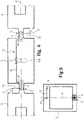
- Figures 4 and 5 show an alternative upper support of bogieless car units 3. It consists of a leverage 70 comprising first levers 71 pivotably mounted at both ends of an upper part of the supported car 3, substantially at the central longitudinal vertical plane A of the rail vehicle 1 which at the same time passes via the pivot systems 6 of the lower supports 5, so as to turn around substantially vertical axles and facing towards the supporting cars 3; second levers 72 which are pivotably connected with ends of these first levers 71 pointing towards the supporting cars 3 and whose support points 9 on the side of opposite ends of the car unit 3 supported on the supporting car units 2 are located on opposite sides of said vertical plane A; and third levers 73 arranged fixedly on the first levers 71 such that they point towards a side of the rail vehicle 1, each towards the same side of the rail vehicle 1 (the levers 71 and 73 substantially at a right angle mutually); and a connecting rod 74 pivotably mounted at ends of the third levers 73; wherein the inclination device 8 is arranged in the connecting rod 74 in order to elong
- a hydraulic cylinder driven by a hydraulic unit 110 is used as the inclination device 8.
- the inclination device 8 is shortened or elongated, i.e. a hydraulic fluid is supplied on either side of the hydraulic cylinder.
- This leverage enables the inclination to be applied on each side of the rail vehicle.
- This arrangement is advantageous also while the rail vehicle 1 is running since it halves the angle value between the supporting car units 2 into the angle value of the vertical position of the supported car unit 3.
- this also enables a version which only extends or shortens the connecting bar 74, only allowing inclination in one direction.
- electric linear motion bars or pneumatic cylinders may also be selected as the inclination devices 8.
- Other solutions performing linear motion are also possible.
- the use of the inclination devices 8 is locked, but at stops they are available for use by a driver through a push button provided in the driver's compartment.
- the driver further has to also possibly select the direction of inclination, depending on the side of the rail vehicle 1 on which the stop resides.
Landscapes
- Engineering & Computer Science (AREA)
- Mechanical Engineering (AREA)
- Transportation (AREA)
- Vehicle Body Suspensions (AREA)
- Platform Screen Doors And Railroad Systems (AREA)
- Vehicle Cleaning, Maintenance, Repair, Refitting, And Outriggers (AREA)
- Handcart (AREA)
- Seats For Vehicles (AREA)
- Fittings On The Vehicle Exterior For Carrying Loads, And Devices For Holding Or Mounting Articles (AREA)
- Machines For Laying And Maintaining Railways (AREA)
- Chain Conveyers (AREA)
Claims (11)
- Schienenfahrzeug (1), insbesondere eine Straßenbahn, das Stützwaggoneinheiten (2), die mit Drehgestellen (4) ausgerüstet sind, und mindestens eine gestützte Waggoneinheit (3) ohne Drehgestell umfasst, diemittels unteren Stützen (5) zwischen den Waggoneinheiten (2, 3) zwischen zwei Stützwaggoneinheiten (2) gestützt wird, wobei die unteren Stützen (5) ein Schwenksystem (6) umfassen, das ein Drehen zwischen den Waggoneinheiten (2, 3) in alle Richtungen erlaubt; unddurch mindestens eine obere Stütze (7) zwischen der gestützten Waggoneinheit (3) und der Stützwaggoneinheit (2) gestützt wird, wobei die obere Stütze (7) eine vertikale Position der gestützten Waggoneinheit (3) mit Bezug auf die Stützwaggoneinheit (2) führt,dadurch gekennzeichnet ist, dass zum Ein- und Aussteigen von Passagieren an Haltestellen die obere Stütze (7) eine Neigungsvorrichtung (8) zum Versetzen mindestens einer gestützten Waggoneinheit (3) aus einem vertikalen Winkel der Stützwaggoneinheit (2) umfasst,wobei die obere Stütze eine Reaktionsstange (7) umfasst, die im Wesentlichen quer zu einer Längsrichtung der Waggons (2, 3) verläuft und an der die Neigungsvorrichtung (8) zum Verlängern oder Verkürzen der Reaktionsstange (7) und somit zum Bewirken der Neigung der gestützten Waggoneinheit (3) angeordnet ist.
- Schienenfahrzeug wie in Anspruch 1 beansprucht, dadurch gekennzeichnet ist, dass die Verwendung der Neigungsvorrichtungen (8) verriegelt ist, während das Schienenfahrzeug (1) fährt, an Haltestellen zur Verwendung durch einen Fahrer über eine Drucktaste, die in der Fahrerkabine bereitgestellt ist, aber verfügbar sind.
- Schienenfahrzeug nach Anspruch 1, dadurch gekennzeichnet, dass diese Neigung nur zum Neigen der gestützten Waggoneinheiten (3) nur an Haltestellen angeordnet ist, wenn das Schienenfahrzeug (1) zum Ein- und Aussteigen der Passagiere steht.
- Schienenfahrzeug nach einem der vorhergehenden Ansprüche, dadurch gekennzeichnet, dass die Reaktionsstangen (7) an beiden Enden des gestützten Waggons (3) angeordnet sind, wobei deren Stützpunkte (9) an den Stützwaggoneinheiten (2) an gegenüberliegenden Enden der gestützten Waggoneinheit (3) auf gegenüberliegenden Seiten einer zentralen vertikalen Längsebene (A) des Schienenfahrzeugs (1) positioniert sind, die gleichzeitig via die Schwenksysteme (6) der unteren Stützen (5) verläuft.
- Schienenfahrzeug nach einem der vorhergehenden Ansprüche, dadurch gekennzeichnet, dass die Neigungsvorrichtung (8) ein Hydraulikzylinder ist.
- Schienenfahrzeug nach einem der Ansprüche 1 bis 4, dadurch gekennzeichnet, dass die Neigungsvorrichtung (8) eine elektrische lineare Bewegungsstange ist.
- Schienenfahrzeug nach einem der Ansprüche 1 bis 4, dadurch gekennzeichnet, dass die Neigungsvorrichtung (8) ein Pneumatikzylinder ist.
- Schienenfahrzeug (1), insbesondere eine Straßenbahn, das Stützwaggoneinheiten (2), die mit Drehgestellen (4) ausgerüstet sind, und mindestens eine gestützte Waggoneinheit (3) ohne Drehgestell umfasst, diemittels unteren Stützen (5) zwischen den Waggoneinheiten (2, 3) zwischen zwei Stützwaggoneinheiten (2) gestützt wird, wobei die unteren Stützen (5) ein Schwenksystem (6) umfassen, das ein Drehen zwischen den Waggoneinheiten (2, 3) in alle Richtungen erlaubt; unddurch mindestens eine obere Stütze (70) zwischen der gestützten Waggoneinheit (3) und der Stützwaggoneinheit (2) gestützt wird, wobei die obere Stütze (70) eine vertikale Position der gestützten Waggoneinheit (3) mit Bezug auf die Stützwaggoneinheit (2) führt,dadurch gekennzeichnet ist, dass zum Ein- und Aussteigen von Passagieren an Haltestellen die obere Stütze (70) eine Neigungsvorrichtung (8) zum Versetzen mindestens einer gestützten Waggoneinheit (3) aus einem vertikalen Winkel der Stützwaggoneinheit (3) umfasst,wobei die obere Stütze aus einer Hebelanordnung (70) besteht, die erste Hebel (71), die schwenkbar an beiden Enden des gestützten Waggons (3) im Wesentlichen in der zentralen vertikalen Längsebene (A) des Schienenfahrzeugs (1), die gleichzeitig via die Schwenksysteme (6) der unteren Stützen (5) verläuft, schwenkbar montiert sind, um sich um im Wesentlichen vertikale Achsen zu drehen und den Stützwaggons (3) zugewandt zu sein; zweite Hebel (72), die schwenkbar mit Enden der ersten Hebel (71), die zu den Stützwaggons (3) zeigen, verbunden sind und deren Stützpunkte (9) an gegenüberliegenden Enden der gestützten Waggoneinheit (3), die auf den Stützwaggoneinheiten (2) gestützt wird, auf gegenüberliegenden Seiten der vertikalen Ebene (A) positioniert sind; dritte Hebel (73), die fest in den ersten Hebeln (71) angeordnet sind, derart, dass sie zu einer Seite des Schienenfahrzeugs (1) zeigen, jeder zur selben Seite des Schienenfahrzeugs (1); und eine Verbindungsstange (74), die schwenkbar an Enden der dritten Hebel (73) montiert sind, umfasst; wobei die Neigungsvorrichtung (8) in der Verbindungsstange (74) angeordnet ist, um dieselbe zu verlängern oder zu verkürzen und so eine Neigung der gestützten Waggoneinheit (3) zu bewirken.
- Schienenfahrzeug nach Anspruch 8, dadurch gekennzeichnet, dass die Neigungsvorrichtung (8) ein Hydraulikzylinder ist.
- Schienenfahrzeug nach Anspruch 8, dadurch gekennzeichnet, dass die Neigungsvorrichtung (8) eine elektrische lineare Bewegungsstange ist.
- Schienenfahrzeug nach Anspruch 8, dadurch gekennzeichnet, dass die Neigungsvorrichtung (8) ein Pneumatikzylinder ist.
Applications Claiming Priority (2)
| Application Number | Priority Date | Filing Date | Title |
|---|---|---|---|
| FI20155246A FI126686B (fi) | 2015-04-07 | 2015-04-07 | Kiskokulkuneuvo |
| PCT/FI2016/050207 WO2016162597A1 (en) | 2015-04-07 | 2016-04-04 | Rail vehicle |
Publications (4)
| Publication Number | Publication Date |
|---|---|
| EP3280628A1 EP3280628A1 (de) | 2018-02-14 |
| EP3280628A4 EP3280628A4 (de) | 2018-12-19 |
| EP3280628B1 true EP3280628B1 (de) | 2022-10-26 |
| EP3280628B8 EP3280628B8 (de) | 2022-12-07 |
Family
ID=57073055
Family Applications (1)
| Application Number | Title | Priority Date | Filing Date |
|---|---|---|---|
| EP16776179.0A Active EP3280628B8 (de) | 2015-04-07 | 2016-04-04 | Schienenfahrzeug |
Country Status (8)
| Country | Link |
|---|---|
| EP (1) | EP3280628B8 (de) |
| JP (1) | JP6472928B2 (de) |
| CN (1) | CN107406088B (de) |
| ES (1) | ES2935918T3 (de) |
| FI (1) | FI126686B (de) |
| PL (1) | PL3280628T3 (de) |
| RU (1) | RU2669498C1 (de) |
| WO (1) | WO2016162597A1 (de) |
Families Citing this family (2)
| Publication number | Priority date | Publication date | Assignee | Title |
|---|---|---|---|---|
| DE102017214308A1 (de) * | 2017-08-17 | 2019-02-21 | Bombardier Transportation Gmbh | Fahrzeug zur Personenbeförderung, insbesondere ein Multigelenk-Schienenfahrzeug und Einrichtung zur Anpassung der Einstiegshöhe |
| DE102019211074A1 (de) * | 2019-07-25 | 2021-01-28 | Siemens Mobility GmbH | Schienenfahrzeug mit einer krafteinbringenden Anordnung |
Family Cites Families (18)
| Publication number | Priority date | Publication date | Assignee | Title |
|---|---|---|---|---|
| FR2751603B1 (fr) * | 1996-07-26 | 1998-10-09 | Lohr Ind | Liaison composite articulee entre deux voitures successives d'un vehicule de transport en commun separees par un module intermediaire porte par un essieu |
| JP4019642B2 (ja) * | 2001-03-01 | 2007-12-12 | いすゞ自動車株式会社 | 車高調整式エアサスペンション装置 |
| JP2004306733A (ja) * | 2003-04-04 | 2004-11-04 | Hitachi Ltd | 車両用懸架装置、車体姿勢制御方法及びその装置 |
| DE10343536A1 (de) * | 2003-09-19 | 2005-05-04 | Siemens Ag | Großräumiges Fahrzeug zur Personenbeförderung, insbesondere Schienenfahrzeug, mit gelenkig verbundenen Wagenkästen |
| DE202004020784U1 (de) * | 2004-03-26 | 2006-02-02 | Siemens Ag | Fahrzeug, insbesondere spurgeführtes Fahrzeug, mit gelenkig verbundenen Wagenkästen |
| JP4452117B2 (ja) * | 2004-04-05 | 2010-04-21 | 三菱重工業株式会社 | 車両の車体間走行安定化装置 |
| JP4249659B2 (ja) * | 2004-05-25 | 2009-04-02 | 近畿車輌株式会社 | 車体の連接装置 |
| DE102005016713A1 (de) * | 2005-04-11 | 2006-10-12 | Bombardier Transportation Gmbh | Mehrgliedriges Fahrzeug |
| JP4410763B2 (ja) | 2005-06-02 | 2010-02-03 | 三菱重工業株式会社 | 軌道系車両装置 |
| DE102005041163A1 (de) * | 2005-08-16 | 2007-02-22 | Bombardier Transportation Gmbh | Fahrzeug mit Wankstützen |
| DE102005041162A1 (de) * | 2005-08-16 | 2007-02-22 | Bombardier Transportation Gmbh | Fahrzeug mit Wankstützen |
| RU2302956C1 (ru) * | 2005-12-30 | 2007-07-20 | Закрытое акционерное общество "Рубин" | Трамвайный вагон с пониженным уровнем пола |
| JP5094029B2 (ja) * | 2006-03-22 | 2012-12-12 | 川崎重工業株式会社 | 車両の車体間安定化装置 |
| DE102006018960A1 (de) * | 2006-04-24 | 2007-10-25 | Robert Bosch Gmbh | Verfahren zum Betreiben einer Brennkraftmaschine, sowie Brennkraftmaschine |
| CN101204963B (zh) * | 2006-12-22 | 2010-05-12 | 西南交通大学 | 独立轮对单轴转向架柔性耦合径向调节机构 |
| DE102008063768A1 (de) * | 2008-12-22 | 2010-07-01 | Bombardier Transportation Gmbh | Fahrzeug mit Wankstützen |
| CN201626424U (zh) * | 2010-04-12 | 2010-11-10 | 长春轨道客车股份有限公司 | 一种100%低地板轻轨车多模块铰接系统 |
| ES2543682T3 (es) * | 2013-02-09 | 2015-08-21 | HÜBNER GmbH & Co. KG | Dispositivo dispuesto en el sector de techo de dos componentes de vehículo unidos articuladamente para la limitación del movimiento de cabeceo relativo de los componentes de vehículo entre sí |
-
2015
- 2015-04-07 FI FI20155246A patent/FI126686B/fi active IP Right Grant
-
2016
- 2016-04-04 EP EP16776179.0A patent/EP3280628B8/de active Active
- 2016-04-04 JP JP2018503826A patent/JP6472928B2/ja active Active
- 2016-04-04 PL PL16776179.0T patent/PL3280628T3/pl unknown
- 2016-04-04 RU RU2017134075A patent/RU2669498C1/ru active
- 2016-04-04 ES ES16776179T patent/ES2935918T3/es active Active
- 2016-04-04 CN CN201680017948.5A patent/CN107406088B/zh active Active
- 2016-04-04 WO PCT/FI2016/050207 patent/WO2016162597A1/en not_active Ceased
Also Published As
| Publication number | Publication date |
|---|---|
| CN107406088B (zh) | 2019-10-01 |
| FI126686B (fi) | 2017-03-31 |
| JP2018510813A (ja) | 2018-04-19 |
| WO2016162597A1 (en) | 2016-10-13 |
| EP3280628A1 (de) | 2018-02-14 |
| ES2935918T3 (es) | 2023-03-13 |
| FI20155246L (fi) | 2016-10-08 |
| PL3280628T3 (pl) | 2023-04-17 |
| CN107406088A (zh) | 2017-11-28 |
| EP3280628A4 (de) | 2018-12-19 |
| EP3280628B8 (de) | 2022-12-07 |
| RU2669498C1 (ru) | 2018-10-11 |
| JP6472928B2 (ja) | 2019-02-20 |
Similar Documents
| Publication | Publication Date | Title |
|---|---|---|
| US20110265682A1 (en) | Variable gauge bogie with rotating axles and fixed track gauge change installation | |
| US4702173A (en) | Vehicle supported in cantilever fashion and switching of at rail divergent junctions | |
| EP2789523B1 (de) | Drehgestell für eine Seilbahnanlage und Seilbahnanlage mit einem solchen Drehgestell | |
| EP3280628B1 (de) | Schienenfahrzeug | |
| CN109208398A (zh) | 道岔和跨座式轨道系统 | |
| JP7444457B2 (ja) | 静的鉄道線路構成を用いた鉄道車切替システムおよび方法 | |
| US3352254A (en) | Monorail train | |
| RU2657643C2 (ru) | Поезд, нагруженный рельсами, для транспортировки сваренных по длине рельсов с зажимными приспособлениями для рельсового профиля | |
| JP7428797B2 (ja) | 高架鉄道状の路線網における自走式車両用の移行装置 | |
| KR20060041144A (ko) | 단순화한 트럭 장착형 브레이크 시스템 | |
| US640050A (en) | Suspension-railway and car or carriage therefor. | |
| CN200974948Y (zh) | 道岔铺设纵移平车 | |
| US2856864A (en) | Articulated cars | |
| KR830004104A (ko) | 철도차량용 대차(truck for railroad car) | |
| EP3875685A1 (de) | Schienenfahrzeug zum transport von schienen | |
| US508478A (en) | Elevated railway | |
| US972997A (en) | Transportation system. | |
| USRE2799E (en) | Improvement in elevated railways | |
| WO2019031984A1 (ru) | Скоростная автономная транспортная система подвесного типа "страус" шумовского | |
| US1022659A (en) | Railroad-terminal. | |
| US2123423A (en) | Brake equipment for articulated cars | |
| SU897619A1 (ru) | Подвесна опора тормозной рычажной передачи тележки железнодорожного транспортного средства | |
| ES1246208U (es) | Vehículo ferroviario para el transporte de carriles | |
| US262640A (en) | Grip apparatus for cable-ways | |
| US245785A (en) | Device for cable wats |
Legal Events
| Date | Code | Title | Description |
|---|---|---|---|
| STAA | Information on the status of an ep patent application or granted ep patent |
Free format text: STATUS: THE INTERNATIONAL PUBLICATION HAS BEEN MADE |
|
| PUAI | Public reference made under article 153(3) epc to a published international application that has entered the european phase |
Free format text: ORIGINAL CODE: 0009012 |
|
| STAA | Information on the status of an ep patent application or granted ep patent |
Free format text: STATUS: REQUEST FOR EXAMINATION WAS MADE |
|
| 17P | Request for examination filed |
Effective date: 20171106 |
|
| AK | Designated contracting states |
Kind code of ref document: A1 Designated state(s): AL AT BE BG CH CY CZ DE DK EE ES FI FR GB GR HR HU IE IS IT LI LT LU LV MC MK MT NL NO PL PT RO RS SE SI SK SM TR |
|
| AX | Request for extension of the european patent |
Extension state: BA ME |
|
| DAV | Request for validation of the european patent (deleted) | ||
| DAX | Request for extension of the european patent (deleted) | ||
| A4 | Supplementary search report drawn up and despatched |
Effective date: 20181116 |
|
| RIC1 | Information provided on ipc code assigned before grant |
Ipc: B61D 3/10 20060101ALI20181112BHEP Ipc: B61D 13/00 20060101ALI20181112BHEP Ipc: B61G 5/02 20060101AFI20181112BHEP Ipc: B61G 7/12 20060101ALI20181112BHEP |
|
| STAA | Information on the status of an ep patent application or granted ep patent |
Free format text: STATUS: EXAMINATION IS IN PROGRESS |
|
| 17Q | First examination report despatched |
Effective date: 20210331 |
|
| GRAP | Despatch of communication of intention to grant a patent |
Free format text: ORIGINAL CODE: EPIDOSNIGR1 |
|
| STAA | Information on the status of an ep patent application or granted ep patent |
Free format text: STATUS: GRANT OF PATENT IS INTENDED |
|
| INTG | Intention to grant announced |
Effective date: 20220613 |
|
| RAP3 | Party data changed (applicant data changed or rights of an application transferred) |
Owner name: HELSINGIN KAUPUNGIN LIIKENNELIIKELAITOS |
|
| GRAS | Grant fee paid |
Free format text: ORIGINAL CODE: EPIDOSNIGR3 |
|
| GRAA | (expected) grant |
Free format text: ORIGINAL CODE: 0009210 |
|
| STAA | Information on the status of an ep patent application or granted ep patent |
Free format text: STATUS: THE PATENT HAS BEEN GRANTED |
|
| AK | Designated contracting states |
Kind code of ref document: B1 Designated state(s): AL AT BE BG CH CY CZ DE DK EE ES FI FR GB GR HR HU IE IS IT LI LT LU LV MC MK MT NL NO PL PT RO RS SE SI SK SM TR |
|
| REG | Reference to a national code |
Ref country code: GB Ref legal event code: FG4D |
|
| REG | Reference to a national code |
Ref country code: CH Ref legal event code: EP |
|
| REG | Reference to a national code |
Ref country code: DE Ref legal event code: R096 Ref document number: 602016075897 Country of ref document: DE |
|
| REG | Reference to a national code |
Ref country code: CH Ref legal event code: PK Free format text: BERICHTIGUNG B8 Ref country code: AT Ref legal event code: REF Ref document number: 1526854 Country of ref document: AT Kind code of ref document: T Effective date: 20221115 |
|
| REG | Reference to a national code |
Ref country code: IE Ref legal event code: FG4D |
|
| REG | Reference to a national code |
Ref country code: DE Ref legal event code: R081 Ref document number: 602016075897 Country of ref document: DE Owner name: PAEAEKAUPUNKISEUDUN KAUPUNKILIIKENNE OY, FI Free format text: FORMER OWNER: HELSINGIN KAUPUNGIN LIIKENNELIIKELAITOS, HELSINGIN KAUPUNKI, FI |
|
| RAP2 | Party data changed (patent owner data changed or rights of a patent transferred) |
Owner name: PAEAEKAUPUNKISEUDUN KAUPUNKILIIKENNE OY |
|
| REG | Reference to a national code |
Ref country code: NL Ref legal event code: FP |
|
| REG | Reference to a national code |
Ref country code: LT Ref legal event code: MG9D |
|
| REG | Reference to a national code |
Ref country code: ES Ref legal event code: FG2A Ref document number: 2935918 Country of ref document: ES Kind code of ref document: T3 Effective date: 20230313 |
|
| REG | Reference to a national code |
Ref country code: SK Ref legal event code: T3 Ref document number: E 41148 Country of ref document: SK |
|
| REG | Reference to a national code |
Ref country code: FR Ref legal event code: PLFP Year of fee payment: 8 |
|
| PG25 | Lapsed in a contracting state [announced via postgrant information from national office to epo] |
Ref country code: SE Free format text: LAPSE BECAUSE OF FAILURE TO SUBMIT A TRANSLATION OF THE DESCRIPTION OR TO PAY THE FEE WITHIN THE PRESCRIBED TIME-LIMIT Effective date: 20221026 Ref country code: PT Free format text: LAPSE BECAUSE OF FAILURE TO SUBMIT A TRANSLATION OF THE DESCRIPTION OR TO PAY THE FEE WITHIN THE PRESCRIBED TIME-LIMIT Effective date: 20230227 Ref country code: NO Free format text: LAPSE BECAUSE OF FAILURE TO SUBMIT A TRANSLATION OF THE DESCRIPTION OR TO PAY THE FEE WITHIN THE PRESCRIBED TIME-LIMIT Effective date: 20230126 Ref country code: LT Free format text: LAPSE BECAUSE OF FAILURE TO SUBMIT A TRANSLATION OF THE DESCRIPTION OR TO PAY THE FEE WITHIN THE PRESCRIBED TIME-LIMIT Effective date: 20221026 Ref country code: FI Free format text: LAPSE BECAUSE OF FAILURE TO SUBMIT A TRANSLATION OF THE DESCRIPTION OR TO PAY THE FEE WITHIN THE PRESCRIBED TIME-LIMIT Effective date: 20221026 |
|
| PG25 | Lapsed in a contracting state [announced via postgrant information from national office to epo] |
Ref country code: RS Free format text: LAPSE BECAUSE OF FAILURE TO SUBMIT A TRANSLATION OF THE DESCRIPTION OR TO PAY THE FEE WITHIN THE PRESCRIBED TIME-LIMIT Effective date: 20221026 Ref country code: LV Free format text: LAPSE BECAUSE OF FAILURE TO SUBMIT A TRANSLATION OF THE DESCRIPTION OR TO PAY THE FEE WITHIN THE PRESCRIBED TIME-LIMIT Effective date: 20221026 Ref country code: IS Free format text: LAPSE BECAUSE OF FAILURE TO SUBMIT A TRANSLATION OF THE DESCRIPTION OR TO PAY THE FEE WITHIN THE PRESCRIBED TIME-LIMIT Effective date: 20230226 Ref country code: HR Free format text: LAPSE BECAUSE OF FAILURE TO SUBMIT A TRANSLATION OF THE DESCRIPTION OR TO PAY THE FEE WITHIN THE PRESCRIBED TIME-LIMIT Effective date: 20221026 Ref country code: GR Free format text: LAPSE BECAUSE OF FAILURE TO SUBMIT A TRANSLATION OF THE DESCRIPTION OR TO PAY THE FEE WITHIN THE PRESCRIBED TIME-LIMIT Effective date: 20230127 |
|
| REG | Reference to a national code |
Ref country code: DE Ref legal event code: R097 Ref document number: 602016075897 Country of ref document: DE |
|
| PG25 | Lapsed in a contracting state [announced via postgrant information from national office to epo] |
Ref country code: SM Free format text: LAPSE BECAUSE OF FAILURE TO SUBMIT A TRANSLATION OF THE DESCRIPTION OR TO PAY THE FEE WITHIN THE PRESCRIBED TIME-LIMIT Effective date: 20221026 Ref country code: EE Free format text: LAPSE BECAUSE OF FAILURE TO SUBMIT A TRANSLATION OF THE DESCRIPTION OR TO PAY THE FEE WITHIN THE PRESCRIBED TIME-LIMIT Effective date: 20221026 Ref country code: DK Free format text: LAPSE BECAUSE OF FAILURE TO SUBMIT A TRANSLATION OF THE DESCRIPTION OR TO PAY THE FEE WITHIN THE PRESCRIBED TIME-LIMIT Effective date: 20221026 |
|
| PG25 | Lapsed in a contracting state [announced via postgrant information from national office to epo] |
Ref country code: AL Free format text: LAPSE BECAUSE OF FAILURE TO SUBMIT A TRANSLATION OF THE DESCRIPTION OR TO PAY THE FEE WITHIN THE PRESCRIBED TIME-LIMIT Effective date: 20221026 |
|
| PLBE | No opposition filed within time limit |
Free format text: ORIGINAL CODE: 0009261 |
|
| STAA | Information on the status of an ep patent application or granted ep patent |
Free format text: STATUS: NO OPPOSITION FILED WITHIN TIME LIMIT |
|
| 26N | No opposition filed |
Effective date: 20230727 |
|
| REG | Reference to a national code |
Ref country code: AT Ref legal event code: UEP Ref document number: 1526854 Country of ref document: AT Kind code of ref document: T Effective date: 20221026 |
|
| PG25 | Lapsed in a contracting state [announced via postgrant information from national office to epo] |
Ref country code: SI Free format text: LAPSE BECAUSE OF FAILURE TO SUBMIT A TRANSLATION OF THE DESCRIPTION OR TO PAY THE FEE WITHIN THE PRESCRIBED TIME-LIMIT Effective date: 20221026 |
|
| PG25 | Lapsed in a contracting state [announced via postgrant information from national office to epo] |
Ref country code: LU Free format text: LAPSE BECAUSE OF NON-PAYMENT OF DUE FEES Effective date: 20230404 |
|
| REG | Reference to a national code |
Ref country code: BE Ref legal event code: MM Effective date: 20230430 |
|
| PG25 | Lapsed in a contracting state [announced via postgrant information from national office to epo] |
Ref country code: MC Free format text: LAPSE BECAUSE OF FAILURE TO SUBMIT A TRANSLATION OF THE DESCRIPTION OR TO PAY THE FEE WITHIN THE PRESCRIBED TIME-LIMIT Effective date: 20221026 |
|
| PG25 | Lapsed in a contracting state [announced via postgrant information from national office to epo] |
Ref country code: MC Free format text: LAPSE BECAUSE OF FAILURE TO SUBMIT A TRANSLATION OF THE DESCRIPTION OR TO PAY THE FEE WITHIN THE PRESCRIBED TIME-LIMIT Effective date: 20221026 |
|
| REG | Reference to a national code |
Ref country code: IE Ref legal event code: MM4A |
|
| PG25 | Lapsed in a contracting state [announced via postgrant information from national office to epo] |
Ref country code: BE Free format text: LAPSE BECAUSE OF NON-PAYMENT OF DUE FEES Effective date: 20230430 |
|
| PG25 | Lapsed in a contracting state [announced via postgrant information from national office to epo] |
Ref country code: IE Free format text: LAPSE BECAUSE OF NON-PAYMENT OF DUE FEES Effective date: 20230404 |
|
| PG25 | Lapsed in a contracting state [announced via postgrant information from national office to epo] |
Ref country code: IE Free format text: LAPSE BECAUSE OF NON-PAYMENT OF DUE FEES Effective date: 20230404 |
|
| PG25 | Lapsed in a contracting state [announced via postgrant information from national office to epo] |
Ref country code: BG Free format text: LAPSE BECAUSE OF FAILURE TO SUBMIT A TRANSLATION OF THE DESCRIPTION OR TO PAY THE FEE WITHIN THE PRESCRIBED TIME-LIMIT Effective date: 20221026 |
|
| PG25 | Lapsed in a contracting state [announced via postgrant information from national office to epo] |
Ref country code: BG Free format text: LAPSE BECAUSE OF FAILURE TO SUBMIT A TRANSLATION OF THE DESCRIPTION OR TO PAY THE FEE WITHIN THE PRESCRIBED TIME-LIMIT Effective date: 20221026 |
|
| PGFP | Annual fee paid to national office [announced via postgrant information from national office to epo] |
Ref country code: RO Payment date: 20250304 Year of fee payment: 10 |
|
| PGFP | Annual fee paid to national office [announced via postgrant information from national office to epo] |
Ref country code: PL Payment date: 20250305 Year of fee payment: 10 Ref country code: CZ Payment date: 20250304 Year of fee payment: 10 |
|
| PGFP | Annual fee paid to national office [announced via postgrant information from national office to epo] |
Ref country code: SK Payment date: 20250304 Year of fee payment: 10 |
|
| PGFP | Annual fee paid to national office [announced via postgrant information from national office to epo] |
Ref country code: NL Payment date: 20250416 Year of fee payment: 10 |
|
| PGFP | Annual fee paid to national office [announced via postgrant information from national office to epo] |
Ref country code: DE Payment date: 20250423 Year of fee payment: 10 |
|
| PGFP | Annual fee paid to national office [announced via postgrant information from national office to epo] |
Ref country code: ES Payment date: 20250512 Year of fee payment: 10 |
|
| PGFP | Annual fee paid to national office [announced via postgrant information from national office to epo] |
Ref country code: IT Payment date: 20250418 Year of fee payment: 10 |
|
| PGFP | Annual fee paid to national office [announced via postgrant information from national office to epo] |
Ref country code: FR Payment date: 20250417 Year of fee payment: 10 |
|
| PGFP | Annual fee paid to national office [announced via postgrant information from national office to epo] |
Ref country code: CH Payment date: 20250501 Year of fee payment: 10 |
|
| PGFP | Annual fee paid to national office [announced via postgrant information from national office to epo] |
Ref country code: AT Payment date: 20250424 Year of fee payment: 10 |
|
| PG25 | Lapsed in a contracting state [announced via postgrant information from national office to epo] |
Ref country code: CY Free format text: LAPSE BECAUSE OF FAILURE TO SUBMIT A TRANSLATION OF THE DESCRIPTION OR TO PAY THE FEE WITHIN THE PRESCRIBED TIME-LIMIT; INVALID AB INITIO Effective date: 20160404 |
|
| PG25 | Lapsed in a contracting state [announced via postgrant information from national office to epo] |
Ref country code: HU Free format text: LAPSE BECAUSE OF FAILURE TO SUBMIT A TRANSLATION OF THE DESCRIPTION OR TO PAY THE FEE WITHIN THE PRESCRIBED TIME-LIMIT; INVALID AB INITIO Effective date: 20160404 |
|
| PGFP | Annual fee paid to national office [announced via postgrant information from national office to epo] |
Ref country code: GB Payment date: 20260325 Year of fee payment: 11 |
|
| PGFP | Annual fee paid to national office [announced via postgrant information from national office to epo] |
Ref country code: TR Payment date: 20260324 Year of fee payment: 11 |