EP3280592B1 - Imagerie multicouche dotée d'une couche d'encre transparente à brillant élevé - Google Patents
Imagerie multicouche dotée d'une couche d'encre transparente à brillant élevé Download PDFInfo
- Publication number
- EP3280592B1 EP3280592B1 EP16777445.4A EP16777445A EP3280592B1 EP 3280592 B1 EP3280592 B1 EP 3280592B1 EP 16777445 A EP16777445 A EP 16777445A EP 3280592 B1 EP3280592 B1 EP 3280592B1
- Authority
- EP
- European Patent Office
- Prior art keywords
- substrate
- ink
- clear ink
- clear
- light source
- Prior art date
- Legal status (The legal status is an assumption and is not a legal conclusion. Google has not performed a legal analysis and makes no representation as to the accuracy of the status listed.)
- Active
Links
- 238000003384 imaging method Methods 0.000 title description 3
- 239000000976 ink Substances 0.000 claims description 141
- 239000000758 substrate Substances 0.000 claims description 69
- 230000005855 radiation Effects 0.000 claims description 40
- 238000007641 inkjet printing Methods 0.000 claims description 36
- 238000007639 printing Methods 0.000 claims description 34
- 238000000034 method Methods 0.000 claims description 16
- 238000000151 deposition Methods 0.000 claims description 8
- 230000005670 electromagnetic radiation Effects 0.000 claims description 7
- 230000008569 process Effects 0.000 claims description 5
- 230000004888 barrier function Effects 0.000 claims description 4
- 238000001035 drying Methods 0.000 claims description 4
- XLYOFNOQVPJJNP-UHFFFAOYSA-N water Substances O XLYOFNOQVPJJNP-UHFFFAOYSA-N 0.000 claims description 3
- 239000002904 solvent Substances 0.000 claims description 2
- 230000000979 retarding effect Effects 0.000 claims 2
- 230000000977 initiatory effect Effects 0.000 claims 1
- 230000000712 assembly Effects 0.000 description 19
- 238000000429 assembly Methods 0.000 description 19
- 238000012545 processing Methods 0.000 description 6
- 238000004891 communication Methods 0.000 description 4
- 238000010586 diagram Methods 0.000 description 4
- 238000005299 abrasion Methods 0.000 description 3
- 238000010438 heat treatment Methods 0.000 description 3
- 230000001681 protective effect Effects 0.000 description 3
- 239000002966 varnish Substances 0.000 description 3
- 238000013459 approach Methods 0.000 description 2
- 230000005540 biological transmission Effects 0.000 description 2
- 238000000576 coating method Methods 0.000 description 2
- 238000011161 development Methods 0.000 description 2
- 230000018109 developmental process Effects 0.000 description 2
- 238000005516 engineering process Methods 0.000 description 2
- 239000012530 fluid Substances 0.000 description 2
- QSHDDOUJBYECFT-UHFFFAOYSA-N mercury Chemical compound [Hg] QSHDDOUJBYECFT-UHFFFAOYSA-N 0.000 description 2
- 239000006096 absorbing agent Substances 0.000 description 1
- 239000000654 additive Substances 0.000 description 1
- 239000000853 adhesive Substances 0.000 description 1
- 230000001070 adhesive effect Effects 0.000 description 1
- 239000003963 antioxidant agent Substances 0.000 description 1
- 238000003491 array Methods 0.000 description 1
- 239000003139 biocide Substances 0.000 description 1
- 230000015556 catabolic process Effects 0.000 description 1
- 230000001413 cellular effect Effects 0.000 description 1
- 239000000919 ceramic Substances 0.000 description 1
- 239000011248 coating agent Substances 0.000 description 1
- 238000010276 construction Methods 0.000 description 1
- 238000006731 degradation reaction Methods 0.000 description 1
- 239000000539 dimer Substances 0.000 description 1
- 230000006870 function Effects 0.000 description 1
- 238000009499 grossing Methods 0.000 description 1
- 238000007373 indentation Methods 0.000 description 1
- 239000003112 inhibitor Substances 0.000 description 1
- 239000004611 light stabiliser Substances 0.000 description 1
- 239000000463 material Substances 0.000 description 1
- 229910052753 mercury Inorganic materials 0.000 description 1
- 229910052751 metal Inorganic materials 0.000 description 1
- 239000002184 metal Substances 0.000 description 1
- 238000012986 modification Methods 0.000 description 1
- 230000004048 modification Effects 0.000 description 1
- 239000000178 monomer Substances 0.000 description 1
- 239000002105 nanoparticle Substances 0.000 description 1
- 230000002093 peripheral effect Effects 0.000 description 1
- 239000004033 plastic Substances 0.000 description 1
- 238000006116 polymerization reaction Methods 0.000 description 1
- 238000004549 pulsed laser deposition Methods 0.000 description 1
- 239000007787 solid Substances 0.000 description 1
- 239000004094 surface-active agent Substances 0.000 description 1
- 239000003017 thermal stabilizer Substances 0.000 description 1
Images


Classifications
-
- B—PERFORMING OPERATIONS; TRANSPORTING
- B41—PRINTING; LINING MACHINES; TYPEWRITERS; STAMPS
- B41J—TYPEWRITERS; SELECTIVE PRINTING MECHANISMS, i.e. MECHANISMS PRINTING OTHERWISE THAN FROM A FORME; CORRECTION OF TYPOGRAPHICAL ERRORS
- B41J2/00—Typewriters or selective printing mechanisms characterised by the printing or marking process for which they are designed
- B41J2/005—Typewriters or selective printing mechanisms characterised by the printing or marking process for which they are designed characterised by bringing liquid or particles selectively into contact with a printing material
- B41J2/01—Ink jet
- B41J2/21—Ink jet for multi-colour printing
- B41J2/2107—Ink jet for multi-colour printing characterised by the ink properties
- B41J2/2114—Ejecting specialized liquids, e.g. transparent or processing liquids
-
- B—PERFORMING OPERATIONS; TRANSPORTING
- B41—PRINTING; LINING MACHINES; TYPEWRITERS; STAMPS
- B41J—TYPEWRITERS; SELECTIVE PRINTING MECHANISMS, i.e. MECHANISMS PRINTING OTHERWISE THAN FROM A FORME; CORRECTION OF TYPOGRAPHICAL ERRORS
- B41J11/00—Devices or arrangements of selective printing mechanisms, e.g. ink-jet printers or thermal printers, for supporting or handling copy material in sheet or web form
- B41J11/0015—Devices or arrangements of selective printing mechanisms, e.g. ink-jet printers or thermal printers, for supporting or handling copy material in sheet or web form for treating before, during or after printing or for uniform coating or laminating the copy material before or after printing
- B41J11/002—Curing or drying the ink on the copy materials, e.g. by heating or irradiating
- B41J11/0021—Curing or drying the ink on the copy materials, e.g. by heating or irradiating using irradiation
- B41J11/00214—Curing or drying the ink on the copy materials, e.g. by heating or irradiating using irradiation using UV radiation
-
- B—PERFORMING OPERATIONS; TRANSPORTING
- B41—PRINTING; LINING MACHINES; TYPEWRITERS; STAMPS
- B41J—TYPEWRITERS; SELECTIVE PRINTING MECHANISMS, i.e. MECHANISMS PRINTING OTHERWISE THAN FROM A FORME; CORRECTION OF TYPOGRAPHICAL ERRORS
- B41J11/00—Devices or arrangements of selective printing mechanisms, e.g. ink-jet printers or thermal printers, for supporting or handling copy material in sheet or web form
- B41J11/0015—Devices or arrangements of selective printing mechanisms, e.g. ink-jet printers or thermal printers, for supporting or handling copy material in sheet or web form for treating before, during or after printing or for uniform coating or laminating the copy material before or after printing
- B41J11/002—Curing or drying the ink on the copy materials, e.g. by heating or irradiating
- B41J11/0021—Curing or drying the ink on the copy materials, e.g. by heating or irradiating using irradiation
- B41J11/00216—Curing or drying the ink on the copy materials, e.g. by heating or irradiating using irradiation using infrared [IR] radiation or microwaves
-
- B—PERFORMING OPERATIONS; TRANSPORTING
- B41—PRINTING; LINING MACHINES; TYPEWRITERS; STAMPS
- B41M—PRINTING, DUPLICATING, MARKING, OR COPYING PROCESSES; COLOUR PRINTING
- B41M7/00—After-treatment of prints, e.g. heating, irradiating, setting of the ink, protection of the printed stock
- B41M7/0045—After-treatment of prints, e.g. heating, irradiating, setting of the ink, protection of the printed stock using protective coatings or film forming compositions cured by mechanical wave energy, e.g. ultrasonics, cured by electromagnetic radiation or waves, e.g. ultraviolet radiation, electron beams, or cured by magnetic or electric fields, e.g. electric discharge, plasma
-
- B—PERFORMING OPERATIONS; TRANSPORTING
- B41—PRINTING; LINING MACHINES; TYPEWRITERS; STAMPS
- B41M—PRINTING, DUPLICATING, MARKING, OR COPYING PROCESSES; COLOUR PRINTING
- B41M7/00—After-treatment of prints, e.g. heating, irradiating, setting of the ink, protection of the printed stock
- B41M7/0081—After-treatment of prints, e.g. heating, irradiating, setting of the ink, protection of the printed stock using electromagnetic radiation or waves, e.g. ultraviolet radiation, electron beams
-
- B—PERFORMING OPERATIONS; TRANSPORTING
- B41—PRINTING; LINING MACHINES; TYPEWRITERS; STAMPS
- B41M—PRINTING, DUPLICATING, MARKING, OR COPYING PROCESSES; COLOUR PRINTING
- B41M7/00—After-treatment of prints, e.g. heating, irradiating, setting of the ink, protection of the printed stock
- B41M7/0027—After-treatment of prints, e.g. heating, irradiating, setting of the ink, protection of the printed stock using protective coatings or layers by lamination or by fusion of the coatings or layers
Definitions
- Various embodiments relate generally to inkjet printing and curing. More particularly, various embodiments concern inkjet systems configured for multilayer imaging with a high-gloss clear ink layer.
- Inkjet printing and energy-curable inks have experienced significant development over the last decade. In general, these developments have focused on more effective and efficient means to cure the ink after it has been deposited onto a substrate.
- the first energy-curable inkjet printing systems used medium pressure Mercury (vapor) bulbs. These bulbs were capable of producing a significant peak intensity (W/cm 2 ) and doses of UV radiation (J/cm 2 ) in a variety of wavelengths.
- WO 2015110619 A1 discloses an UV inkjet printer comprising an UV radiation device and a shutter system to create a first radiation zone on a receiver and to create a second irradiation zone. The shutter means of the shutter system can be opened or closed.
- WO 20141126578 A1 discloses a method of printing an image using UV curable ink. The method comprises after a first amount of time has passed applying a first amount of UV light by a first region and after a second amount of time has passed applying a second amount of UV light by a second region.
- WO2011099557 A1 discloses an inkjet printer comprising a UV radiation device and a mask for adjusting the illuminance distribution.
- inkjet printing systems and techniques for improving the gloss of multilayer images printed on a substrate provide clear, curable inks additional time to settle and level out before being cured. Said another way, the inkjet printing systems described herein prevent clear ink from being immediately exposed to a curing assembly and instead selectively introduce the clear ink to the curing assembly after a certain amount of time (e.g., seconds or minutes after being deposited onto a substrate).
- colored ink(s) could be deposited onto the substrate by a first row of print heads, and clear ink could be deposited onto the substrate by a second row of print heads.
- Clear ink is typically ejected on top of a color layer so that the clear layer can act as a protective overcoat (e.g., for outdoor weathering, abrasion resistance, or anti-graffiti), gloss flood coat or varnish, or spot gloss.
- clear ink could also be ejected directly onto the substrate (e.g., as a primer).
- the clear ink is given time to settle before being exposed to a curing assembly. This can be accomplished by making structural adjustments to the inkjet printing system. For example, a bracket could be attached to the curing assembly that prevents radiation from striking a section of the substrate onto which clear ink has been deposited. As another example, a barrier could be erected immediately prior to the clear ink print head(s) that shields the recently-deposited clear ink from radiation.
- the inkjet printing system may include a single curing assembly or multiple curing assemblies.
- a first curing assembly could be configured to cure the color layer, while a second curing assembly could be configured to cure the clear layer.
- the first and second curing assemblies are configured to emit different types of radiation.
- the first curing assembly may be configured to emit electromagnetic radiation of subtype C (UVC)
- the second curing assembly may be configured to emit electromagnetic radiation of subtype A (UVA), subtype B (UVB), subtype V (UW), or a combination thereof.
- Various embodiments allow for true multilayer printing of a color coat (e.g., a color image) and a high-gloss clear coat in a single step. That is, multilayer printing can be accomplished without moving the print media backward, removing and reinserting the print media into the printing system, or incorporating a second step.
- Various embodiments also allow multilayer prints to be executed on roll-to-roll inkjet printers and on hybrid inkjet printers that are capable of printing on both flexible roll-form print media and rigid print media (e.g., individual sheets).
- the systems described herein allow clear coatings to flow out and level so that it can act as a primer, protective overcoat (e.g., for outdoor weathering, abrasion resistance, or anti-graffiti), gloss flood coat or varnish, or spot gloss.
- protective overcoat e.g., for outdoor weathering, abrasion resistance, or anti-graffiti
- gloss flood coat or varnish e.g., for outdoor weathering, abrasion resistance, or anti-graffiti
- spot gloss e.g., for outdoor weathering, abrasion resistance, or anti-graffiti
- Figure 1 depicts the feed direction of media (also referred to herein as a "substrate") as it advances through an inkjet printing system 100.
- the inkjet printing system 100 could be a conventional inkjet hybrid or roll-to-roll printer.
- An inkjet printing system 100 typically includes a printer carriage 102 that contains one or more print heads that deposit inks or other fluids onto the flexible or rigid substrate 104.
- Figure 1 also depicts the path of a printer carriage 102 that shuttles laterally across the substrate 104. The path traversed by the printer carriage 102 as it shuttles laterally across the substrate 104 is normally substantially perpendicular to the media feed direction.
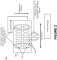
- Figure 2 is a diagram of an inkjet printing system 200 configured to deposit both colored ink and clear ink on a substrate 208.
- Many inkjet printing systems include at least one print head that applies a clear, curable ink or fluid to the substrate 208.
- the inkjet printing system 200 includes a printer carriage 202 that houses print heads 204 that eject clear ink and print heads 206 that eject colored ink.
- conventional inkjet printing systems do not provide the clear ink sufficient time to settle and level out before being cured.
- the print head(s) 204 may be in line with the print heads 206 responsible for ejecting colored ink, may be placed in front of or behind the other print heads 206 (e.g., in a separate row), or may be attached to the front or back of the printer carriage 202.
- print heads 204, 206 in a printer carriage 202 are arranged in multiple rows, it is possible to print multiple layers on top of one another (i.e., produce a multilayer print) in a single pass of the substrate 208 through the printing system 200.
- printing systems whose carriages shuttle back and forth laterally across a substrate may use a first row of print head(s) to print a color layer (e.g., an image or text) and a second row of print head(s) to print a clear layer.
- the clear layer may cover some or all of the color layer. For example, clear ink may only be deposited on a portion of a color image.
- a section of a curing lamp 210 may be covered or disabled. More specifically, the colored ink can be deposited on a segment of substrate that is exposed to an active area of the curing lamp 210 immediately or very soon after printing. However, the curing lamp 210 may be blocked or turned off in an inactive area that passes over the clear ink. Eventually, as the substrate 208 advances through the printing system 200, the clear ink moves past the inactive area of the curing lamp 210 and reaches a position where the clear ink is exposed to sufficient radiation to initiate the curing process. The duration of time during which the clear ink is not exposed to radiation (also referred to as "time-to-lamp”) is sufficiently large to allow the individual droplets of clear ink to flow together and level out, which yields a higher gloss than would otherwise occur.
- Time-to-lamp for the clear ink can also be increased incrementally by curing with a lamp that leads the print heads 204, 206 and the carriage 202 as it traverses the media 208 and by printing uni-directionally.
- a lamp that leads the print heads 204, 206 and the carriage 202 as it traverses the media 208 and by printing uni-directionally.
- the top layer could include patches of both clear ink and colored inks or only patches of clear ink, or could be a flood coat of clear ink.
- the top layer could include patches of both clear ink and colored inks or only patches of clear ink, or could be a flood coat of clear ink.
- Figure 3 depicts the underside of an inkjet printing system 300 that is able to cure ink deposited on a substrate using one or more curing assemblies 308a-b.
- Colored inks are initially deposited on the substrate by one or more colored ink print heads 304, and at least partially cured by active sections of the curing assemblies 308a-b.
- the colored ink print head(s) 304 may be arranged in a row as shown in Figure 3 .
- the curing assemblies 308a-b meanwhile, could be curing lamps that are disposed on opposite sides of the printer carriage 302.
- clear ink can be deposited on top of the color image by one or more clear ink print heads 306.
- the clear ink could be deposited by a second row of print head(s) or a subset of the print heads in the second row (e.g., only the outermost print heads on each end).
- a portion of each curing assembly 308a-b is blocked (as shown by crosshatched areas 310a-b) so that the section of substrate between the dashed lines is not exposed to any radiation from the curing assemblies 308a-b.
- the clear ink can be cured by radiation emitted by the curing assemblies 308a-b.
- the inkjet printing system 300 is configured to transport the substrate at a particular speed so that the clear ink is provided sufficient time to settle before being exposed to the curing assemblies 308a-b.
- a conveyor may advance the substrate at a particular speed while depositing ink on the substrate, and then decrease the speed of advancement (or halt advancement entirely) when the section of the substrate resides within the dead zone.
- the colored ink(s) and the clear ink(s) deposited onto the substrate may be, for example, a solid curable ink, a water-based curable ink, or a solvent-based curable ink.
- the curing assemblies 308a-b could include fluorescent bulbs, light emitting diodes, low pressure bulbs, or exited dimer (excimer) lamps and/or lasers.
- the curing assemblies 308a-b may be low-pressure mercury vapor lamps configured to emit UV radiation.
- the curing assemblies 308a-b may be configured to emit wavelengths of electromagnetic radiation subtype A (UVA), subtype B (UVB), subtype C (UVC), subtype V (UW), or some combination thereof.
- UW wavelengths generally measure between 395 nm and 445 nm.
- UVA wavelengths generally measure between 315 nanometers (nm) and 395 nm.
- UVB wavelengths generally measure between 280 nm and 315 nm.
- UVC wavelengths generally measure between 100 nm and 280 nm.
- UVC subtype V
- UVC wavelengths generally measure between 100 nm and 280 nm.
- some embodiments may characterize wavelengths of 285 nm as UVC..
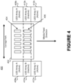
- Figure 4 depicts the underside of an inkjet printing system 400 that is able to cure ink deposited on a substrate using a segmented array of LEDs.
- the inkjet printing system 400 can include a printer carriage 402 that houses one or more colored ink print heads 404 and one or more clear ink print heads 406.
- the colored ink print head(s) 404 and the clear ink print head(s) 406 are housed within separate printer carriages.
- the colored ink print head(s) 404 can initially deposit colored ink on the substrate that is at least partially cured by the first LED array(s) 408a-b.
- the first LED array 408 could be disposed on one or both sides of the printer carriage 402.
- clear ink can be deposited on the substrate by the clear ink print head(s) 406.
- the second LED array(s) 410a-b is inactive, the section of substrate that is disposed between the dashed lines is not exposed to any radiation (and thus is not cured). The lack of radiation provides the clear ink sufficient time to settle and level out so that the gloss can be maximized.
- both the colored layer and the clear layer can be cured by the third LED array(s) 412a-b.
- the end result is a multilayer image that includes at least a color layer (e.g., a colored image) that is disposed beneath a clear layer.
- the clear layer can cover some or all of the colored layer. For example, clear ink may only be deposited on particular segments of the colored layer as a spot gloss.
- Each array of LEDs could be configured to emit radiation having a particular wavelength.
- the first LED array(s) 408a-b may emit UVC wavelengths
- the third LED array(s) 412a-b may emit UVA wavelengths.
- one or more of the LED arrays are mixed light sources that includes multiple light sources (e.g., fluorescent bulbs or light emitting diodes) that are configured to emit two different types of electromagnetic radiation.
- Figures 5A-C are bottom, side, and end views of a curing assembly 500 that includes a shielding bracket 504, which blocks radiation in a particular area. More specifically, the shielding bracket 504 can be attached the housing 502 of the curing assembly 500 using one or more fasteners.
- the fasteners can include magnets, mechanical clips/tracks, or some kind of adhesive. Additionally or alternatively, the shielding bracket 504 and/or the housing 502 may include holes or indentations that are suitable for screws, nuts and bolts, etc.
- the shielding bracket 504 need not be made of any particular material so long as the shielding bracket 504 is able to prevent radiation that is emitted by the curing assembly 500 from reaching ink that has been deposited on a substrate disposed beneath the curing assembly 500. But the shielding bracket 504 could be comprised of a metal or plastic that is readily cleanable and suffers limited degradation over time.
- the shielding bracket 504 can be attached to the housing 502 to create a dead zone where the substrate is left undisturbed. More specifically, the shielding bracket 504 ensures that only certain segments of the substrate are exposed to the radiation emitted by the curing assembly at a given point in time.
- the shielding bracket 504 could be disposed near the front, middle, or back of the curing assembly 500.
- the position of the shielding bracket 504 may be determined based on the position of the print head(s) responsible for depositing clear ink on the media.
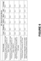
- Figure 6 is a table that shows a comparison of gloss values for different color blocks onto which a clear overcoat has been printed using various embodiments described herein and conventional printer setups.
- the sets of color blocks were printed using a Vutek H2000 Pro with light smoothing, double shutters, medium cure, and standard speed.
- the gloss values illustrate the effectiveness of the systems and techniques described herein in achieving high gloss. More specifically, the gloss values illustrate the importance of providing clear ink sufficient time to settle before being cured.
- Figure 7 shows an inkjet printing system 700 that includes fixed print heads 702, 706 for depositing color inks and clear ink and curing systems 704, 708 for curing the ink deposited on a substrate 710.
- a conveyor 712 may be responsible for advancing the substrate 710 through the inkjet printing system 700.
- drying systems are included instead or, or in addition to, the curing systems 704, 708.
- the inkjet printing system 700 also includes a dead zone where no light or radiation (e.g., actinic UV radiation) is permitted to reach the substrate 710.
- the dead zone is typically created by making structural adjustments to the inkjet printing system 700.
- a shielding bracket could be affixed to a curing system as shown by Figure 6 .
- a barrier could be erected the prevents radiation emitted by the curing system 704 for the color layer from passing a certain point.
- the time that a section of the substrate 710 spends within the dead zone may be based on numerous factors. For example, the segment may travel through the dead zone slowly if a moderate amount of clear ink is deposited by the clear ink print head(s) 706, while the segment may stop in dead zone entirely if a large amount of clear ink is deposited by the clear ink print head(s) 706.
- the conveyor 712 may advance the substrate through the dead zone unimpeded if a small amount of clear ink (or no clear ink at all) was deposited on the segment by the clear ink print head(s) 706.
- Numerous embodiments are also amenable to performing water-based drying in a similar fashion. That is, drying and/or heating could be performed rather than energy-based (e.g., UV) curing.
- the curing assemblies may be replaced by heating assemblies that include arc lamps, LEDs, infrared (IR) lamps, ceramic heaters, etc.
- the heating assembling can be blocked or removed entirely from an area adjacent to the clear ink print head(s) 706 so that the clear ink has sufficient time to settle.
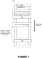
- Figure 8 depicts a process 800 for curing a multilayer image that includes a layer of colored ink and a layer of clear ink.
- Printing instructions are initially received by an inkjet printing system from a source (step 801).
- the source may communicate printing instructions through a local physical connection (e.g., via a universal serial bus (USB) connection) and/or a remotely connection (e.g. via a local Wi-Fi network, Bluetooth peer to peer connection, or an Internet service provider (ISP) coupled to the local Wi-Fi network via a router).
- a local physical connection e.g., via a universal serial bus (USB) connection
- a remotely connection e.g. via a local Wi-Fi network, Bluetooth peer to peer connection, or an Internet service provider (ISP) coupled to the local Wi-Fi network via a router.
- ISP Internet service provider
- the inkjet printing system then begins the printing process by depositing colored ink on a substrate to form a color layer in accordance with the printing instructions (step 802).
- the color layer is then at least partially cured by being exposed to a first curing assembling (step 803).
- the first curing assembly could include, for example, LEDs configured to emit UV radiation at a particular wavelength that is based at least in part on the composition of the colored ink,
- the color layer could be partially or entirely cured by the curing assembly during this step.
- the inkjet printing system then deposits clear ink on at least a portion of the color layer to form a clear layer (step 804).
- the clear layer can act as a protective overcoat (e.g., for outdoor weathering, abrasion resistance, or anti-graffiti), a gloss flood coat or varnish, or a spot gloss.
- the inkjet printing system is designed so that the clear ink has sufficient time to settle before being cured (step 805). This can be done in multiple ways. For example, a shielding bracket could be affixed to the curing assembly that prevents radiation from reaching the substrate. As another example, sufficient space may exist between the first curing assembly and the clear ink print head(s) such that radiation does not affect clear ink deposited onto the substrate.
- the clear layer is then at least partially cured by a second curing assembly (step 806).
- the first and second curing assemblies are part of the same curing assembly.
- a shielding bracket may separate a single curing assembly into multiple segments that emit radiation.
- the first and second curing assemblies could instead be distinct curing assemblies.
- the distinct curing assemblies could be configured to emit the same or different types of radiation.
- a clear layer could be initially deposited by the clear ink print head(s) onto the substrate as a clear primer that is disposed beneath the color layer.
- steps described here could be altered in a variety of ways. For instance, the order of the steps may be rearranged, sub-steps may be performed in parallel, some illustrated steps may be omitted, other steps may be included, etc.
- certain steps may be consolidated into a single step and the actions represented by a single step may be alternatively represented as a collection of sub-steps.
- the clear, radiation-curable inks described above preferably comprise the following components at the certain composition levels, which are listed below:
- FIG. 9 is a block diagram of a processing system 900 that may be used to implement certain features of some of the embodiments described herein.
- the processing system 900 may include or be part of a server, a personal computer, a tablet, a personal digital assistant (PDA), a mobile phone, a network-connected (“smart”) device, or another electronic device capable of providing instructions to a printing system.
- PDA personal digital assistant
- smart network-connected
- the processing system 900 may include one or more central processing units (“processors”) 902, memory 904, a communication device 906, and an input/output device 908 (e.g., keyboards, pointing devices, and touch-sensitive displays) that are connected to an interconnect 910.
- processors central processing units
- memory 904 volatile and non-volatile memory
- communication device 906 non-volatile memory
- input/output device 908 e.g., keyboards, pointing devices, and touch-sensitive displays
- the interconnect 910 is illustrated as an abstraction that represents any one or more separate physical buses, point-to-point connections, or both connected by appropriate bridges, adapters, or controllers.
- the interconnect 910 may include, for example a system bus, a peripheral component interconnect (PCI) bus or PCI-Express bus, a HyperTransport or industry standard architecture (ISA) bus, a small computer system interface (SCSI) bus, a universal serial bus (USB), IIC (12C) bus, or an Institute of Electrical and Electronics Engineers (IEEE) standard 1394 bus, also referred to as "Firewire.”
- PCI peripheral component interconnect
- ISA industry standard architecture
- SCSI small computer system interface
- USB universal serial bus
- IIC (12C) IIC
- IEEE Institute of Electrical and Electronics Engineers
- the memory 904 is computer-readable storage media that may store instructions that implement at least portions of the various embodiments.
- the data structures and message structures may be stored or transmitted via a data transmission medium (e.g., a signal on a communications link).
- a data transmission medium e.g., a signal on a communications link.
- Various communications links may be used, such as the Internet, a local area network, a wide area network, or a point-to-point dial-up connection.
- computer readable media can include computer-readable storage media (e.g., non-transitory media) and computer-readable transmission media.
- the instructions stored in memory 904 can be implemented as software and/or firmware to program one or more processors 902 to carry out the actions described above.
- such software or firmware may be initially provided to the processor 902 by downloading it from a remote system through the communication device 906, such as an Ethernet adapter, cable modem, Wi-Fi adapter, cellular transceiver, or Bluetooth transceiver.
- programmable circuitry e.g., one or more microprocessors
- software and/or firmware entirely in special-purpose hardwired (i.e., non-programmable, circuitry), or in a combination of such forms.
- Special-purpose hardwired circuitry may be in the form of, for example, one or more ASICs, PLDs, FPGAs, etc.
Landscapes
- Health & Medical Sciences (AREA)
- General Health & Medical Sciences (AREA)
- Toxicology (AREA)
- Physics & Mathematics (AREA)
- Electromagnetism (AREA)
- Engineering & Computer Science (AREA)
- Mechanical Engineering (AREA)
- Plasma & Fusion (AREA)
- Ink Jet (AREA)
- Laminated Bodies (AREA)
Claims (14)
- Système d'impression (100, 200, 300, 400, 700), comprenant:
un chariot (102, 202, 302, 402) qui comporteune première tête d'impression (204, 206, 304, 306, 404, 406, 702, 706) qui dépose de l'encre colorée sur un substrat (104, 208, 710), etune deuxième tête d'impression (204, 206, 304, 306, 404, 406, 702, 706) qui dépose de l'encre claire sur le substrat (104, 208, 710),dans lequel la deuxième tête d'impression (204, 206, 304, 306, 404, 406, 702, 706) est disposée en aval de la première tête d'impression (204, 206, 304, 306, 404, 406, 702, 706) dans la direction d'alimentation de support;une source de lumière qui est configurée pour émettre un rayonnement pour durcir l'encre déposée sur le substrat (104, 208, 710),
dans lequel la source de lumière est disposée le long d'un côté du chariot (102, 202, 302, 402); etun support (504) qui est fixé de manière statique aux côtés opposés d'un boîtier de la source de lumière de sorte que le support recouvre une partie de la source de lumière pour empêcher temporairement que le rayonnement n'atteigne un segment du substrat (104, 208, 710) sur lequel a été déposée l'encre claire, etdans lequel le support (504) est positionné sensiblement de manière alignée sur la deuxième tête d'impression (204, 206, 304, 306, 404, 406, 702, 706) de sorte que l'encre claire déposée sur le segment du substrat (104, 208, 710) ne soit pas immédiatement exposée au rayonnement émis par la source de lumière pendant un laps de temps pendant lequel il est permis à l'encre claire de se stabiliser, etdans lequel le laps de temps est basé sur une largeur du support. - Système d'impression (100, 200, 300, 400, 700) selon la revendication 1, dans lequel l'encre colorée et l'encre claire sont des encres durcissables aux rayons ultraviolets.
- Système d'impression (100, 200, 300, 400, 700) selon la revendication 1, dans lequel l'encre colorée est une encre diluée à base d'eau ou une encre diluée à base de solvant qui est au moins partiellement durcie par la source de lumière immédiatement après avoir été déposée sur le substrat (104, 208, 710) par la première tête d'impression (204, 206, 304, 306, 404, 406, 702, 706).
- Système d'impression (100, 200, 300, 400, 700) selon la revendication 1, dans lequel l'encre colorée comprend un premier photo-initiateur adapté pour absorber une première plage de longueurs d'onde émises par la source de lumière.
- Système d'impression (100, 200, 300, 400, 700) selon la revendication 4, dans lequel l'encre claire comprend un deuxième photo-initiateur adapté pour absorber une deuxième plage de longueurs d'onde émises par la source de lumière.
- Système d'impression (100, 200, 300, 400, 700) selon la revendication 5, dans lequel la source de lumière est une source de lumière mixte qui comporte une pluralité de diodes électroluminescentes qui sont configurées pour émettre la première plage de longueurs d'onde et la deuxième plage de longueurs d'onde, dans lequel les première et deuxième plages de longueurs d'onde correspondent à un rayonnement électromagnétique de sous-type A (UVA), de sous-type B (UVB), de sous-type C (UVC) ou de sous-type V (UW), et dans lequel la source de lumière émet le rayonnement à partir d'une ampoule fluorescente, d'une diode électroluminescente, d'une ampoule de basse pression, d'une ampoule de moyenne pression, d'une lampe excimère ou d'un laser excimère.
- Procédé comprenant le fait de:retenir un substrat (104, 208, 710) sur un transporteur (712) qui déplace le substrat (104, 208, 710) à travers un système d'impression à jet d'encre (100, 200, 300, 400, 700);déposer de l'encre colorée sur le substrat (104, 208, 710) à l'aide d'une première tête d'impression (204, 206, 304, 306, 404, 406, 702, 706) pour former une couche colorée;laisser durcir au moins une partie de la couche colorée en exposant l'encre colorée à une première source de lumière,dans laquelle la première source de lumière est configurée pour émettre des longueurs d'onde de rayonnement ultraviolet;déposer de l'encre claire sur au moins une partie de la couche colorée à l'aide d'une deuxième tête d'impression (204, 206, 304, 306, 404, 406, 702, 706);permettre que l'encre claire se stabilise pour former une couche claire avant d'initier un processus de durcissement en retardant le transporteur immédiatement après que l'encre claire soit déposée sur le substrat,dans lequel ledit retardement amène l'encre claire à être disposée sous une source de lumière inactive ou un support qui empêche que le rayonnement n'atteigne le substrat; etlaisser durcir au moins une partie de la couche claire en exposant l'encre claire à une deuxième source de lumière,
dans lequel la deuxième source de lumière est configurée pour émettre des longueurs d'onde de rayonnement ultraviolet. - Procédé selon la revendication 7, dans lequel on laisse l'encre claire se stabiliser pendant un laps de temps particulier avant de l'exposer à la deuxième source de lumière, dans lequel le laps de temps particulier est basé sur une largeur du support (504) ou de la source de lumière inactive, et dans lequel les longueurs d'onde de rayonnement des première et deuxième sources de lumière comprennent un rayonnement électromagnétique de sous-type A (UVA), de sous-type B (UVB), de sous-type C (UVC) ou de sous-type V (UVV).
- Procédé selon la revendication 7, comprenant par ailleurs le fait de:
sécher l'encre colorée et l'encre claire à l'aide d'un ou plusieurs séchoirs disposés en aval des première et deuxième têtes d'impression (204, 206, 304, 306, 404, 406, 702, 706) dans la direction d'alimentation de support. - Procédé selon la revendication 9, dans lequel le laps de temps particulier est basé sur la composition de l'encre claire, la superficie totale de l'au moins une partie de la couche colorée sur laquelle est déposée l'encre claire, la quantité totale d'encre claire déposée sur le substrat (104, 208, 710), ou une certaine combinaison de ces dernières.
- Système d'impression (100, 200, 300, 400, 700), comprenant:un transporteur (712) qui fait avancer un substrat (104, 208, 710) à travers le système d'impression (100, 200, 300, 400, 700) dans une direction d'alimentation de support;une première tête d'impression fixe (204, 206, 304, 306, 404, 406, 702, 706) qui dépose de l'encre colorée sur le substrat (104, 208, 710) pour former une couche colorée;un premier système de durcissement (704, 708) qui durcit au moins partiellement la couche colorée,
dans lequel le premier système de durcissement (704, 708) est disposé en aval de la première tête d'impression fixe (204, 206, 304, 306, 404, 406, 702, 706) dans la direction d'alimentation de support;une barrière sous laquelle le transporteur est à même de faire avancer le substrat dans la direction d'alimentation de support,dans lequel la barrière empêche que le rayonnement émis par le premier système de durcissement ne passe par un point donné dans la direction d'alimentation de support;une deuxième tête d'impression fixe (204, 206, 304, 306, 404, 406, 702, 706) qui dépose de l'encre claire sur le substrat (104, 208, 710) pour former une couche claire,
dans lequel la deuxième tête d'impression fixe (204, 206, 304, 306, 404, 406, 702, 706) est disposée en aval du point donné dans la direction d'alimentation de support, pour assurer que l'encre claire ne soit pas exposée au rayonnement émis par le premier système de durcissement;un deuxième système de durcissement (704, 708) qui durcit au moins partiellement la couche transparente,
dans lequel le deuxième système de durcissement (704, 708) est décalé par rapport à la deuxième tête d'impression fixe (204, 206, 304, 306, 404, 406, 702, 706) d'une distance suffisante pour assurer que l'encre claire ait le temps de se stabiliser avant d'être exposée au rayonnement émis par le deuxième système de durcissement (704, 708). - Système d'impression (100, 200, 300, 400, 700) selon la revendication 11, dans lequel la première tête d'impression (204, 206, 304, 306, 404, 406, 702, 706) est l'une parmi de multiples têtes d'impression (204, 206, 304, 306, 404, 406, 702, 706) configurées pour déposer des encres colorées sur le substrat (104, 208, 710).
- Système d'impression (100, 200, 300, 400, 700) selon la revendication 11, dans lequel les premier et deuxième systèmes de durcissement (704, 708) sont configurés pour émettre un rayonnement électromagnétique de différentes longueurs d'onde.
- Système d'impression (100, 200, 300, 400, 700) selon la revendication 11, dans lequel le transporteur (712) ralentit l'avancement du substrat (104, 208, 710) dans la direction d'alimentation de support ou s'arrête entièrement après que l'encre claire ait été déposée sur le substrat (104, 208, 710) pour donner à l'encre claire le temps de se stabiliser.
Applications Claiming Priority (3)
| Application Number | Priority Date | Filing Date | Title |
|---|---|---|---|
| US201562144754P | 2015-04-08 | 2015-04-08 | |
| US15/093,678 US10000075B2 (en) | 2015-04-08 | 2016-04-07 | Multilayer imaging with a high-gloss clear ink layer |
| PCT/US2016/026822 WO2016164849A1 (fr) | 2015-04-08 | 2016-04-08 | Imagerie multicouche dotée d'une couche d'encre transparente à brillant élevé |
Publications (3)
| Publication Number | Publication Date |
|---|---|
| EP3280592A1 EP3280592A1 (fr) | 2018-02-14 |
| EP3280592A4 EP3280592A4 (fr) | 2019-02-27 |
| EP3280592B1 true EP3280592B1 (fr) | 2023-04-19 |
Family
ID=57073387
Family Applications (1)
| Application Number | Title | Priority Date | Filing Date |
|---|---|---|---|
| EP16777445.4A Active EP3280592B1 (fr) | 2015-04-08 | 2016-04-08 | Imagerie multicouche dotée d'une couche d'encre transparente à brillant élevé |
Country Status (5)
| Country | Link |
|---|---|
| US (2) | US10000075B2 (fr) |
| EP (1) | EP3280592B1 (fr) |
| CN (1) | CN107614263B (fr) |
| ES (1) | ES2950483T3 (fr) |
| WO (1) | WO2016164849A1 (fr) |
Families Citing this family (15)
| Publication number | Priority date | Publication date | Assignee | Title |
|---|---|---|---|---|
| FR3033506B1 (fr) * | 2015-03-11 | 2020-02-21 | Reydel Automotive B.V. | Procede et installation de revetement d'un corps avec formation d'une surface structuree |
| US10000075B2 (en) * | 2015-04-08 | 2018-06-19 | Electronics For Imaging, Inc. | Multilayer imaging with a high-gloss clear ink layer |
| US10180248B2 (en) | 2015-09-02 | 2019-01-15 | ProPhotonix Limited | LED lamp with sensing capabilities |
| US10313556B1 (en) * | 2018-01-16 | 2019-06-04 | Xerox Corporation | Method and system for production quality gloss marks |
| CN108891131B (zh) * | 2018-07-07 | 2019-12-27 | 东莞市图创智能制造有限公司 | 透明油墨固化方法、装置、设备及存储介质 |
| CN108544858A (zh) * | 2018-07-07 | 2018-09-18 | 东莞市图创智能制造有限公司 | 采用光固化油墨的喷墨打印机 |
| JP7149764B2 (ja) * | 2018-08-10 | 2022-10-07 | ローランドディー.ジー.株式会社 | 印刷装置 |
| JP2020062834A (ja) * | 2018-10-18 | 2020-04-23 | 株式会社ミマキエンジニアリング | 印刷装置、印刷方法、パウダリング装置、及びパウダリング方法 |
| WO2020111199A1 (fr) * | 2018-11-30 | 2020-06-04 | Ricoh Company, Ltd. | Dispositif d'éjection de liquide, programme, et procédé de commande d'éjection |
| JP7415431B2 (ja) | 2018-11-30 | 2024-01-17 | 株式会社リコー | 液体吐出装置、プログラムおよび吐出制御方法 |
| JP7243275B2 (ja) * | 2019-02-20 | 2023-03-22 | 株式会社リコー | 液体吐出装置、液体吐出装置における照射制御方法、及び照射制御プログラム |
| JP7305983B2 (ja) * | 2019-02-27 | 2023-07-11 | セイコーエプソン株式会社 | 記録装置および記録方法 |
| JP2022010609A (ja) * | 2020-06-29 | 2022-01-17 | ローランドディー.ジー.株式会社 | インクジェットプリンタ |
| JP2022021648A (ja) * | 2020-07-22 | 2022-02-03 | ブラザー工業株式会社 | 液体吐出装置、液体吐出方法、および液体吐出プログラム |
| CN112622444A (zh) * | 2020-12-31 | 2021-04-09 | 东莞市图创智能制造有限公司 | 打印设备 |
Citations (2)
| Publication number | Priority date | Publication date | Assignee | Title |
|---|---|---|---|---|
| WO2011099557A1 (fr) * | 2010-02-10 | 2011-08-18 | 株式会社ミマキエンジニアリング | Imprimante à jet d'encre |
| US20130100220A1 (en) * | 2009-07-02 | 2013-04-25 | Seiko Epson Corporation | Liquid ejecting apparatus |
Family Cites Families (26)
| Publication number | Priority date | Publication date | Assignee | Title |
|---|---|---|---|---|
| US6550906B2 (en) | 2001-01-02 | 2003-04-22 | 3M Innovative Properties Company | Method and apparatus for inkjet printing using UV radiation curable ink |
| US6739716B2 (en) * | 2002-06-10 | 2004-05-25 | Océ Display Graphics Systems, Inc. | Systems and methods for curing a fluid |
| JP3864903B2 (ja) * | 2002-12-13 | 2007-01-10 | コニカミノルタホールディングス株式会社 | インクジェットプリンタ |
| US20060075917A1 (en) * | 2004-10-08 | 2006-04-13 | Edwards Paul A | Smooth finish UV ink system and method |
| EP1849603B1 (fr) * | 2005-02-18 | 2011-03-30 | Konica Minolta Medical & Graphic, Inc. | Dispositif d'enregistrement à jet d'encre et procédé d'enregistrement à jet d'encre |
| JP4779541B2 (ja) * | 2005-09-29 | 2011-09-28 | コニカミノルタエムジー株式会社 | インクジェット記録装置及び記録方法 |
| JP5028862B2 (ja) * | 2006-05-24 | 2012-09-19 | コニカミノルタエムジー株式会社 | インクジェット記録装置 |
| US7673965B2 (en) | 2006-06-22 | 2010-03-09 | Electronics For Imaging, Inc. | Apparatus and methods for full-width wide format inkjet printing |
| US9132638B2 (en) * | 2008-11-28 | 2015-09-15 | Roland Dg Corporation | Inkjet printer |
| JP5604790B2 (ja) * | 2009-02-04 | 2014-10-15 | セイコーエプソン株式会社 | 印刷方法及び印刷装置 |
| JP5112360B2 (ja) * | 2009-02-27 | 2013-01-09 | 株式会社ミマキエンジニアリング | インクジェットプリンタ及びプリント方法 |
| GB2470067B (en) * | 2009-05-08 | 2013-07-17 | Inca Digital Printers Ltd | Method of printing |
| JP2012066441A (ja) * | 2010-09-22 | 2012-04-05 | Seiko Epson Corp | インクジェット記録装置 |
| JP5702191B2 (ja) * | 2010-10-22 | 2015-04-15 | 株式会社ミマキエンジニアリング | インクジェット記録装置、及び印刷方法 |
| CN103269860B (zh) * | 2010-10-22 | 2016-01-06 | 株式会社御牧工程 | 喷墨记录装置 |
| JP5790234B2 (ja) * | 2010-12-13 | 2015-10-07 | セイコーエプソン株式会社 | 紫外線硬化型インクジェット用インク組成物、これを用いたインクジェット記録装置、これを用いたインクジェット記録方法、及びインクセット |
| JP5653818B2 (ja) * | 2011-03-29 | 2015-01-14 | 富士フイルム株式会社 | インクジェット記録装置及び画像形成方法 |
| US8684511B2 (en) | 2011-08-25 | 2014-04-01 | Electronics For Imaging, Inc. | Ink jet UV pinning for control of gloss |
| US8833922B2 (en) | 2011-11-22 | 2014-09-16 | Electronics For Imaging, Inc. | Printing system for application of a patterned clear layer for reducing gloss banding |
| JP5807544B2 (ja) * | 2011-12-26 | 2015-11-10 | セイコーエプソン株式会社 | 印刷装置、及び、印刷方法 |
| EP2956309B1 (fr) * | 2013-02-15 | 2018-04-25 | Hewlett-Packard Development Company, L.P. | Formation de zones à niveaux de brillance ayant une finition brillante et une finition mate dans une image |
| JP5955275B2 (ja) * | 2013-06-12 | 2016-07-20 | 富士フイルム株式会社 | 画像形成方法、加飾シートの製造方法、成形加工方法、加飾シート成形物の製造方法、インモールド成形品の製造方法 |
| US9757960B2 (en) * | 2014-01-27 | 2017-09-12 | Agfa Graphics Nv | Inkjet printer with UV bulb shutter system including more than one movable shutter |
| US20150273868A1 (en) * | 2014-03-28 | 2015-10-01 | New System S.R.L. | Printing unit and printing apparatus |
| US10000075B2 (en) * | 2015-04-08 | 2018-06-19 | Electronics For Imaging, Inc. | Multilayer imaging with a high-gloss clear ink layer |
| EP3318404B1 (fr) * | 2015-06-30 | 2020-03-04 | Komori Corporation | Dispositif d'impression |
-
2016
- 2016-04-07 US US15/093,678 patent/US10000075B2/en active Active
- 2016-04-08 ES ES16777445T patent/ES2950483T3/es active Active
- 2016-04-08 EP EP16777445.4A patent/EP3280592B1/fr active Active
- 2016-04-08 WO PCT/US2016/026822 patent/WO2016164849A1/fr active Application Filing
- 2016-04-08 CN CN201680033238.1A patent/CN107614263B/zh active Active
-
2018
- 2018-06-18 US US16/011,306 patent/US10752022B2/en active Active
Patent Citations (2)
| Publication number | Priority date | Publication date | Assignee | Title |
|---|---|---|---|---|
| US20130100220A1 (en) * | 2009-07-02 | 2013-04-25 | Seiko Epson Corporation | Liquid ejecting apparatus |
| WO2011099557A1 (fr) * | 2010-02-10 | 2011-08-18 | 株式会社ミマキエンジニアリング | Imprimante à jet d'encre |
Also Published As
| Publication number | Publication date |
|---|---|
| CN107614263B (zh) | 2019-08-27 |
| EP3280592A4 (fr) | 2019-02-27 |
| US20160297210A1 (en) | 2016-10-13 |
| WO2016164849A1 (fr) | 2016-10-13 |
| US10000075B2 (en) | 2018-06-19 |
| US10752022B2 (en) | 2020-08-25 |
| CN107614263A (zh) | 2018-01-19 |
| EP3280592A1 (fr) | 2018-02-14 |
| US20180304647A1 (en) | 2018-10-25 |
| ES2950483T3 (es) | 2023-10-10 |
Similar Documents
| Publication | Publication Date | Title |
|---|---|---|
| EP3280592B1 (fr) | Imagerie multicouche dotée d'une couche d'encre transparente à brillant élevé | |
| US10350911B2 (en) | Selective ink cure | |
| US6457823B1 (en) | Apparatus and method for setting radiation-curable ink | |
| US8702225B2 (en) | Inkjet recording apparatus and image forming method | |
| KR101399027B1 (ko) | 화상 형성 장치 및 화상 형성 방법 | |
| WO2010140294A1 (fr) | Encre, imprimante à jet d'encre, et procédé d'impression | |
| CN104290449B (zh) | 印刷装置及印刷方法 | |
| JP2012526001A5 (fr) | ||
| KR102351102B1 (ko) | Uv 램프 차단 장치를 구비하는 uv 잉크젯 프린터의 경화 시스템 및 그 방법 | |
| JP2012076247A5 (fr) | ||
| US9079427B2 (en) | Staggered ultra-violet curing systems, structures and processes for inkjet printing | |
| JP2012197385A (ja) | 鋼板加飾用紫外線硬化型インクおよび鋼板加飾方法および加飾された化粧鋼板 | |
| JP2013230600A5 (fr) | ||
| US7261408B2 (en) | Printing device with radiation source | |
| CN109649019B (zh) | 打印流体干燥组件、方法和系统 | |
| JP2015100945A (ja) | インク吐出装置 | |
| EP3412471B1 (fr) | Ensemble d'imprimante à jet d'encre avec controle de l'irradiation uv et son procédé de fonctionnement | |
| JP6162548B2 (ja) | プリンタにおける紫外線照射装置 | |
| KR101081711B1 (ko) | Uv 라벨프린터용 잉크경화장치 | |
| JP2010042542A (ja) | 印刷装置及び印刷方法 | |
| JP6955319B2 (ja) | インクジェットプリンターおよびインクジェット印刷方法 | |
| JP2015193089A (ja) | 光源ユニット | |
| KR102441179B1 (ko) | 잉크 경화의 오프타임을 조절하며 잉크의 색감과 질감을 선명하게 하는 uv 프린터용 헤드 | |
| US10449784B2 (en) | Printing device and printing method | |
| US11780166B2 (en) | Preheat build materials with preheating sources |
Legal Events
| Date | Code | Title | Description |
|---|---|---|---|
| STAA | Information on the status of an ep patent application or granted ep patent |
Free format text: STATUS: THE INTERNATIONAL PUBLICATION HAS BEEN MADE |
|
| PUAI | Public reference made under article 153(3) epc to a published international application that has entered the european phase |
Free format text: ORIGINAL CODE: 0009012 |
|
| STAA | Information on the status of an ep patent application or granted ep patent |
Free format text: STATUS: REQUEST FOR EXAMINATION WAS MADE |
|
| 17P | Request for examination filed |
Effective date: 20171006 |
|
| AK | Designated contracting states |
Kind code of ref document: A1 Designated state(s): AL AT BE BG CH CY CZ DE DK EE ES FI FR GB GR HR HU IE IS IT LI LT LU LV MC MK MT NL NO PL PT RO RS SE SI SK SM TR |
|
| AX | Request for extension of the european patent |
Extension state: BA ME |
|
| DAV | Request for validation of the european patent (deleted) | ||
| DAX | Request for extension of the european patent (deleted) | ||
| RIC1 | Information provided on ipc code assigned before grant |
Ipc: B32B 38/14 20060101ALI20181012BHEP Ipc: B41M 7/00 20060101ALI20181012BHEP Ipc: B32B 37/06 20060101ALI20181012BHEP Ipc: B41J 11/00 20060101ALI20181012BHEP Ipc: B41J 2/21 20060101ALI20181012BHEP Ipc: B32B 37/00 20060101AFI20181012BHEP |
|
| A4 | Supplementary search report drawn up and despatched |
Effective date: 20190124 |
|
| RIC1 | Information provided on ipc code assigned before grant |
Ipc: B41M 7/00 20060101ALI20190118BHEP Ipc: B41J 11/00 20060101ALI20190118BHEP Ipc: B32B 37/06 20060101ALI20190118BHEP Ipc: B32B 37/00 20060101AFI20190118BHEP Ipc: B41J 2/21 20060101ALI20190118BHEP Ipc: B32B 38/14 20060101ALI20190118BHEP |
|
| STAA | Information on the status of an ep patent application or granted ep patent |
Free format text: STATUS: EXAMINATION IS IN PROGRESS |
|
| 17Q | First examination report despatched |
Effective date: 20220117 |
|
| RAP3 | Party data changed (applicant data changed or rights of an application transferred) |
Owner name: ELECTRONICS FOR IMAGING, INC. |
|
| REG | Reference to a national code |
Ref country code: DE Ref legal event code: R079 Ref document number: 602016078903 Country of ref document: DE Free format text: PREVIOUS MAIN CLASS: B32B0037000000 Ipc: B41J0011000000 |
|
| GRAP | Despatch of communication of intention to grant a patent |
Free format text: ORIGINAL CODE: EPIDOSNIGR1 |
|
| STAA | Information on the status of an ep patent application or granted ep patent |
Free format text: STATUS: GRANT OF PATENT IS INTENDED |
|
| RIC1 | Information provided on ipc code assigned before grant |
Ipc: B32B 38/14 20060101ALI20220927BHEP Ipc: B32B 37/06 20060101ALI20220927BHEP Ipc: B32B 37/00 20060101ALI20220927BHEP Ipc: B41M 7/00 20060101ALI20220927BHEP Ipc: B41J 2/21 20060101ALI20220927BHEP Ipc: B41J 11/00 20060101AFI20220927BHEP |
|
| INTG | Intention to grant announced |
Effective date: 20221025 |
|
| GRAS | Grant fee paid |
Free format text: ORIGINAL CODE: EPIDOSNIGR3 |
|
| GRAA | (expected) grant |
Free format text: ORIGINAL CODE: 0009210 |
|
| STAA | Information on the status of an ep patent application or granted ep patent |
Free format text: STATUS: THE PATENT HAS BEEN GRANTED |
|
| AK | Designated contracting states |
Kind code of ref document: B1 Designated state(s): AL AT BE BG CH CY CZ DE DK EE ES FI FR GB GR HR HU IE IS IT LI LT LU LV MC MK MT NL NO PL PT RO RS SE SI SK SM TR |
|
| REG | Reference to a national code |
Ref country code: GB Ref legal event code: FG4D |
|
| REG | Reference to a national code |
Ref country code: CH Ref legal event code: EP |
|
| REG | Reference to a national code |
Ref country code: DE Ref legal event code: R096 Ref document number: 602016078903 Country of ref document: DE |
|
| REG | Reference to a national code |
Ref country code: IE Ref legal event code: FG4D |
|
| REG | Reference to a national code |
Ref country code: AT Ref legal event code: REF Ref document number: 1560905 Country of ref document: AT Kind code of ref document: T Effective date: 20230515 |
|
| P01 | Opt-out of the competence of the unified patent court (upc) registered |
Effective date: 20230526 |
|
| REG | Reference to a national code |
Ref country code: LT Ref legal event code: MG9D |
|
| REG | Reference to a national code |
Ref country code: NL Ref legal event code: MP Effective date: 20230419 |
|
| REG | Reference to a national code |
Ref country code: AT Ref legal event code: MK05 Ref document number: 1560905 Country of ref document: AT Kind code of ref document: T Effective date: 20230419 |
|
| PG25 | Lapsed in a contracting state [announced via postgrant information from national office to epo] |
Ref country code: NL Free format text: LAPSE BECAUSE OF FAILURE TO SUBMIT A TRANSLATION OF THE DESCRIPTION OR TO PAY THE FEE WITHIN THE PRESCRIBED TIME-LIMIT Effective date: 20230419 |
|
| REG | Reference to a national code |
Ref country code: ES Ref legal event code: FG2A Ref document number: 2950483 Country of ref document: ES Kind code of ref document: T3 Effective date: 20231010 |
|
| PG25 | Lapsed in a contracting state [announced via postgrant information from national office to epo] |
Ref country code: SE Free format text: LAPSE BECAUSE OF FAILURE TO SUBMIT A TRANSLATION OF THE DESCRIPTION OR TO PAY THE FEE WITHIN THE PRESCRIBED TIME-LIMIT Effective date: 20230419 Ref country code: PT Free format text: LAPSE BECAUSE OF FAILURE TO SUBMIT A TRANSLATION OF THE DESCRIPTION OR TO PAY THE FEE WITHIN THE PRESCRIBED TIME-LIMIT Effective date: 20230821 Ref country code: NO Free format text: LAPSE BECAUSE OF FAILURE TO SUBMIT A TRANSLATION OF THE DESCRIPTION OR TO PAY THE FEE WITHIN THE PRESCRIBED TIME-LIMIT Effective date: 20230719 Ref country code: AT Free format text: LAPSE BECAUSE OF FAILURE TO SUBMIT A TRANSLATION OF THE DESCRIPTION OR TO PAY THE FEE WITHIN THE PRESCRIBED TIME-LIMIT Effective date: 20230419 |
|
| PG25 | Lapsed in a contracting state [announced via postgrant information from national office to epo] |
Ref country code: RS Free format text: LAPSE BECAUSE OF FAILURE TO SUBMIT A TRANSLATION OF THE DESCRIPTION OR TO PAY THE FEE WITHIN THE PRESCRIBED TIME-LIMIT Effective date: 20230419 Ref country code: PL Free format text: LAPSE BECAUSE OF FAILURE TO SUBMIT A TRANSLATION OF THE DESCRIPTION OR TO PAY THE FEE WITHIN THE PRESCRIBED TIME-LIMIT Effective date: 20230419 Ref country code: LV Free format text: LAPSE BECAUSE OF FAILURE TO SUBMIT A TRANSLATION OF THE DESCRIPTION OR TO PAY THE FEE WITHIN THE PRESCRIBED TIME-LIMIT Effective date: 20230419 Ref country code: LT Free format text: LAPSE BECAUSE OF FAILURE TO SUBMIT A TRANSLATION OF THE DESCRIPTION OR TO PAY THE FEE WITHIN THE PRESCRIBED TIME-LIMIT Effective date: 20230419 Ref country code: IS Free format text: LAPSE BECAUSE OF FAILURE TO SUBMIT A TRANSLATION OF THE DESCRIPTION OR TO PAY THE FEE WITHIN THE PRESCRIBED TIME-LIMIT Effective date: 20230819 Ref country code: HR Free format text: LAPSE BECAUSE OF FAILURE TO SUBMIT A TRANSLATION OF THE DESCRIPTION OR TO PAY THE FEE WITHIN THE PRESCRIBED TIME-LIMIT Effective date: 20230419 Ref country code: GR Free format text: LAPSE BECAUSE OF FAILURE TO SUBMIT A TRANSLATION OF THE DESCRIPTION OR TO PAY THE FEE WITHIN THE PRESCRIBED TIME-LIMIT Effective date: 20230720 Ref country code: AL Free format text: LAPSE BECAUSE OF FAILURE TO SUBMIT A TRANSLATION OF THE DESCRIPTION OR TO PAY THE FEE WITHIN THE PRESCRIBED TIME-LIMIT Effective date: 20230419 |
|
| PG25 | Lapsed in a contracting state [announced via postgrant information from national office to epo] |
Ref country code: FI Free format text: LAPSE BECAUSE OF FAILURE TO SUBMIT A TRANSLATION OF THE DESCRIPTION OR TO PAY THE FEE WITHIN THE PRESCRIBED TIME-LIMIT Effective date: 20230419 |
|
| PG25 | Lapsed in a contracting state [announced via postgrant information from national office to epo] |
Ref country code: SK Free format text: LAPSE BECAUSE OF FAILURE TO SUBMIT A TRANSLATION OF THE DESCRIPTION OR TO PAY THE FEE WITHIN THE PRESCRIBED TIME-LIMIT Effective date: 20230419 |
|
| REG | Reference to a national code |
Ref country code: DE Ref legal event code: R097 Ref document number: 602016078903 Country of ref document: DE |
|
| PG25 | Lapsed in a contracting state [announced via postgrant information from national office to epo] |
Ref country code: SM Free format text: LAPSE BECAUSE OF FAILURE TO SUBMIT A TRANSLATION OF THE DESCRIPTION OR TO PAY THE FEE WITHIN THE PRESCRIBED TIME-LIMIT Effective date: 20230419 Ref country code: SK Free format text: LAPSE BECAUSE OF FAILURE TO SUBMIT A TRANSLATION OF THE DESCRIPTION OR TO PAY THE FEE WITHIN THE PRESCRIBED TIME-LIMIT Effective date: 20230419 Ref country code: RO Free format text: LAPSE BECAUSE OF FAILURE TO SUBMIT A TRANSLATION OF THE DESCRIPTION OR TO PAY THE FEE WITHIN THE PRESCRIBED TIME-LIMIT Effective date: 20230419 Ref country code: EE Free format text: LAPSE BECAUSE OF FAILURE TO SUBMIT A TRANSLATION OF THE DESCRIPTION OR TO PAY THE FEE WITHIN THE PRESCRIBED TIME-LIMIT Effective date: 20230419 Ref country code: DK Free format text: LAPSE BECAUSE OF FAILURE TO SUBMIT A TRANSLATION OF THE DESCRIPTION OR TO PAY THE FEE WITHIN THE PRESCRIBED TIME-LIMIT Effective date: 20230419 Ref country code: CZ Free format text: LAPSE BECAUSE OF FAILURE TO SUBMIT A TRANSLATION OF THE DESCRIPTION OR TO PAY THE FEE WITHIN THE PRESCRIBED TIME-LIMIT Effective date: 20230419 |
|
| PLBE | No opposition filed within time limit |
Free format text: ORIGINAL CODE: 0009261 |
|
| STAA | Information on the status of an ep patent application or granted ep patent |
Free format text: STATUS: NO OPPOSITION FILED WITHIN TIME LIMIT |
|
| 26N | No opposition filed |
Effective date: 20240122 |
|
| PGFP | Annual fee paid to national office [announced via postgrant information from national office to epo] |
Ref country code: GB Payment date: 20240229 Year of fee payment: 9 |
|
| PG25 | Lapsed in a contracting state [announced via postgrant information from national office to epo] |
Ref country code: SI Free format text: LAPSE BECAUSE OF FAILURE TO SUBMIT A TRANSLATION OF THE DESCRIPTION OR TO PAY THE FEE WITHIN THE PRESCRIBED TIME-LIMIT Effective date: 20230419 |