US8833922B2 - Printing system for application of a patterned clear layer for reducing gloss banding - Google Patents
Printing system for application of a patterned clear layer for reducing gloss banding Download PDFInfo
- Publication number
- US8833922B2 US8833922B2 US13/302,872 US201113302872A US8833922B2 US 8833922 B2 US8833922 B2 US 8833922B2 US 201113302872 A US201113302872 A US 201113302872A US 8833922 B2 US8833922 B2 US 8833922B2
- Authority
- US
- United States
- Prior art keywords
- clear layer
- ink
- image file
- clear
- carriage
- Prior art date
- Legal status (The legal status is an assumption and is not a legal conclusion. Google has not performed a legal analysis and makes no representation as to the accuracy of the status listed.)
- Active, expires
Links
- 238000007639 printing Methods 0.000 title claims abstract description 24
- 239000000758 substrate Substances 0.000 claims abstract description 38
- 238000000034 method Methods 0.000 claims abstract description 25
- 238000007641 inkjet printing Methods 0.000 claims description 21
- 238000000151 deposition Methods 0.000 claims description 12
- 238000009877 rendering Methods 0.000 claims 4
- 230000003213 activating effect Effects 0.000 claims 1
- 230000000694 effects Effects 0.000 abstract description 9
- 239000000976 ink Substances 0.000 description 138
- 230000008569 process Effects 0.000 description 8
- 239000003086 colorant Substances 0.000 description 7
- 230000008901 benefit Effects 0.000 description 6
- 238000009472 formulation Methods 0.000 description 5
- 239000000203 mixture Substances 0.000 description 5
- 238000013459 approach Methods 0.000 description 4
- 238000000576 coating method Methods 0.000 description 4
- 238000000059 patterning Methods 0.000 description 4
- 239000011248 coating agent Substances 0.000 description 3
- 238000010586 diagram Methods 0.000 description 3
- 230000005670 electromagnetic radiation Effects 0.000 description 3
- 230000006870 function Effects 0.000 description 3
- 239000003349 gelling agent Substances 0.000 description 3
- 239000007788 liquid Substances 0.000 description 3
- 239000004094 surface-active agent Substances 0.000 description 3
- 230000000007 visual effect Effects 0.000 description 3
- 239000013078 crystal Substances 0.000 description 2
- 230000006872 improvement Effects 0.000 description 2
- 230000003287 optical effect Effects 0.000 description 2
- 239000007787 solid Substances 0.000 description 2
- 238000010521 absorption reaction Methods 0.000 description 1
- 230000015572 biosynthetic process Effects 0.000 description 1
- 239000003990 capacitor Substances 0.000 description 1
- 230000001413 cellular effect Effects 0.000 description 1
- 238000010276 construction Methods 0.000 description 1
- 230000007547 defect Effects 0.000 description 1
- 230000008021 deposition Effects 0.000 description 1
- 238000005516 engineering process Methods 0.000 description 1
- 239000003623 enhancer Substances 0.000 description 1
- 238000002474 experimental method Methods 0.000 description 1
- 230000007274 generation of a signal involved in cell-cell signaling Effects 0.000 description 1
- 238000005286 illumination Methods 0.000 description 1
- 230000003116 impacting effect Effects 0.000 description 1
- 230000010354 integration Effects 0.000 description 1
- 239000004973 liquid crystal related substance Substances 0.000 description 1
- 230000000873 masking effect Effects 0.000 description 1
- 230000007246 mechanism Effects 0.000 description 1
- 229910044991 metal oxide Inorganic materials 0.000 description 1
- 150000004706 metal oxides Chemical class 0.000 description 1
- 239000000049 pigment Substances 0.000 description 1
- 230000008092 positive effect Effects 0.000 description 1
- 230000000644 propagated effect Effects 0.000 description 1
- 239000004065 semiconductor Substances 0.000 description 1
- 239000002904 solvent Substances 0.000 description 1
- 230000003068 static effect Effects 0.000 description 1
- 239000000126 substance Substances 0.000 description 1
Images


Classifications
-
- B—PERFORMING OPERATIONS; TRANSPORTING
- B41—PRINTING; LINING MACHINES; TYPEWRITERS; STAMPS
- B41J—TYPEWRITERS; SELECTIVE PRINTING MECHANISMS, i.e. MECHANISMS PRINTING OTHERWISE THAN FROM A FORME; CORRECTION OF TYPOGRAPHICAL ERRORS
- B41J2/00—Typewriters or selective printing mechanisms characterised by the printing or marking process for which they are designed
- B41J2/005—Typewriters or selective printing mechanisms characterised by the printing or marking process for which they are designed characterised by bringing liquid or particles selectively into contact with a printing material
- B41J2/01—Ink jet
- B41J2/21—Ink jet for multi-colour printing
- B41J2/2107—Ink jet for multi-colour printing characterised by the ink properties
- B41J2/2114—Ejecting transparent or white coloured liquids, e.g. processing liquids
-
- B—PERFORMING OPERATIONS; TRANSPORTING
- B41—PRINTING; LINING MACHINES; TYPEWRITERS; STAMPS
- B41J—TYPEWRITERS; SELECTIVE PRINTING MECHANISMS, i.e. MECHANISMS PRINTING OTHERWISE THAN FROM A FORME; CORRECTION OF TYPOGRAPHICAL ERRORS
- B41J11/00—Devices or arrangements of selective printing mechanisms, e.g. ink-jet printers or thermal printers, for supporting or handling copy material in sheet or web form
- B41J11/0015—Devices or arrangements of selective printing mechanisms, e.g. ink-jet printers or thermal printers, for supporting or handling copy material in sheet or web form for treating before, during or after printing or for uniform coating or laminating the copy material before or after printing
- B41J11/002—Curing or drying the ink on the copy materials, e.g. by heating or irradiating
- B41J11/0021—Curing or drying the ink on the copy materials, e.g. by heating or irradiating using irradiation
- B41J11/00212—Controlling the irradiation means, e.g. image-based controlling of the irradiation zone or control of the duration or intensity of the irradiation
-
- B—PERFORMING OPERATIONS; TRANSPORTING
- B41—PRINTING; LINING MACHINES; TYPEWRITERS; STAMPS
- B41J—TYPEWRITERS; SELECTIVE PRINTING MECHANISMS, i.e. MECHANISMS PRINTING OTHERWISE THAN FROM A FORME; CORRECTION OF TYPOGRAPHICAL ERRORS
- B41J11/00—Devices or arrangements of selective printing mechanisms, e.g. ink-jet printers or thermal printers, for supporting or handling copy material in sheet or web form
- B41J11/0015—Devices or arrangements of selective printing mechanisms, e.g. ink-jet printers or thermal printers, for supporting or handling copy material in sheet or web form for treating before, during or after printing or for uniform coating or laminating the copy material before or after printing
- B41J11/002—Curing or drying the ink on the copy materials, e.g. by heating or irradiating
- B41J11/0021—Curing or drying the ink on the copy materials, e.g. by heating or irradiating using irradiation
- B41J11/00218—Constructional details of the irradiation means, e.g. radiation source attached to reciprocating print head assembly or shutter means provided on the radiation source
-
- B—PERFORMING OPERATIONS; TRANSPORTING
- B41—PRINTING; LINING MACHINES; TYPEWRITERS; STAMPS
- B41M—PRINTING, DUPLICATING, MARKING, OR COPYING PROCESSES; COLOUR PRINTING
- B41M7/00—After-treatment of prints, e.g. heating, irradiating, setting of the ink, protection of the printed stock
- B41M7/0081—After-treatment of prints, e.g. heating, irradiating, setting of the ink, protection of the printed stock using electromagnetic radiation or waves, e.g. ultraviolet radiation, electron beams
Definitions
- the invention relates to ultraviolet inkjet printing. More specifically, the invention relates to the application of a visually clear, low print density after-layer of high gloss ink.
- Inkjet printing involves depositing droplets of liquid ink onto a printing medium from one or more printer heads.
- the printer heads are coupled with a container containing ink.
- Ink is ejected from one or more nozzles of the print heads when a piezoelectric crystal in the print head is actuated.
- the piezoelectric crystal generates a pulse in the ink so that the ink expels through the nozzle as a droplet.
- a carriage which holds one or more print heads scans or traverses across the printing medium, while the print heads deposit ink as the printing medium moves.
- Gloss finishes come in various reflective intensities measured in Gloss Number. Gloss Number measures how much light is reflected at a given position. In today's art, gloss finishes are commonplace with solvent based SWF printers, but a high gloss finish is not available on today's UV printers due to the fact that the curing of the droplets of UV ink leaves a matte surface structure, rather than a very smooth finish. The relatively matte looking prints can and do suffer from a print artifact (gloss banding) which is often undesirable for many customer applications.
- Gloss banding is defined as a variation in gloss between subsequent print bands on wide and super-wide format printers. This gloss variation is very visible to the eye and has a directionality component, i.e. the effect changes with viewing angle. The gloss variation is visibly most prominent when the overall gloss of the print is neither very high or very low, i.e. above gloss number value of 10 and below around 60. There have been a variety of methods employed to improve or solve gloss banding.
- Another approach is to provide gloss control on an image via a curing process, in which a curable ink formulation has a variable cure by virtue of a patterned mask placed between the light source and the uncured print. The partially cured image is then fully cured via a flood lamp. The variable gloss is created due to the formation of a rough surface, caused by the variable initial cure.
- the image usually comes out as high gloss from the printing process and the micro-patterning reduces the gloss to become more matte. Therefore, the degree of gloss is controlled by the number and size of the holes in the mask.
- Critical to this approach is the use of a gelling agent.
- the gelling agent ensures the ink is solid at temperatures below about 60° C. to reduce the absorption into paper or other absorptive substrates. Therefore, either the exposed areas become liquid during the UV mask curing or the non-exposed become liquid before they become solid in the final cure, thereby providing the pattern.
- the invention solves the problem of the “gloss banding” defect at the highest print speeds, whilst maintaining a large color gamut.
- the invention involves application of a clear, low print-density after-layer of high gloss ink onto a printed substrate to reduce or eliminate negative printing effects, such as gloss banding.
- Some embodiments of the invention involve a modified printer carriage configured with a plurality of groups of print heads configured for applying colored ink and clear ink after-layers. Some embodiments of the invention involve one or more curing lamps associated with the modified carriage for curing the layers of ink as they are applied.
- Some embodiments of the invention involve a printer system configured with a rail system and a carriage that traverses back-and-forth along the rail as a substrate is moved beneath the rail.
- Other embodiments involve an in-line printing system.
- Some embodiments of the invention involve a method of applying colored ink, curing the colored ink, applying a clear ink layer in a pattern, and curing the clear layer. Some embodiments of the invention involve applying the clear ink layer in preprogrammed pattern. Other embodiments of the invention involve gathering clear ink layer pattern information from the source file itself and applying the clear ink layer as specified. Other embodiments of the invention involve accepting user specifications for the application of the clear ink layer and applying the clear ink layer as specified by the user.
- FIG. 1 illustrates an isometric view of a common printing system adapted for printing images on a variety of substrates
- FIG. 2A illustrates a top down view of an inkjet printer carriage containing ink heads having layout pattern according to some embodiments of the invention
- FIG. 2B illustrates an in-line inkjet printing apparatus configured to deposit a colored ink layer and a clear ink top layer that are cured with a UV light source according to some embodiments of the invention
- FIG. 2C illustrates an in-line inkjet printing apparatus configured to deposit a colored ink layer and a clear ink top layer that are individually cured with multiple UV light sources according to some embodiments of the invention
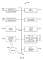
- FIG. 3 illustrates a method of depositing colored ink, curing the colored ink, depositing a clear top coat, and curing the top coat according to some embodiments of the invention
- FIG. 4 illustrates a graph of gloss as a function of clear coat density for a two-coat gloss data with varying mask densities
- FIG. 5 illustrates and example of graphics editing program according to some embodiments of the invention.
- FIG. 6 is a block schematic diagram of a machine in the exemplary form of a computer system within which a set of instructions may be programmed to cause the machine to execute the logic steps of the invention according to some embodiments of the invention.
- the invention is designed to essentially resolve the problem of gloss banding, without negatively impacting other critical features, such as color gamut.
- the invention also allows the customer to control the level of gloss such that the print artifacts are minimized.
- FIG. 1 is an isometric view of a prior art printing system 10 , adapted for printing images on a variety of substrates.
- the printing system 10 includes a base 12 , a transport belt 14 which moves the substrate through the printing system, a rail system 16 attached to the base 12 , and a carriage 18 coupled to the rail system 16 .
- the carriage 18 holds a series of inkjet print heads (not shown) and is attached to a belt 20 which wraps around a pair of pulleys (not shown) positioned on either end of the rail system 16 .
- a carriage motor is coupled to one of the pulleys and rotates the pulley during the printing process. As such, when the carriage motor causes the pulley to rotate, the carriage moves linearly back and forth along the rail system 16 .
- the inkjet print heads deposit ink onto the substrate.
- the carriage 18 moves along the rail system 16 , depositing ink on the substrate as it traverses the rail system 16 .
- the substrate steps ahead by movement of the transport belt 14 to position the substrate for a return traversal and subsequent ink deposit.
- the carriage passes over the same area multiple times, laying down swaths of image pixels each time, building an image consecutively.
- the carriage 18 holds a group of print heads configured to individually jet out colors onto the substrate during a multi-pass printing application. According to the prior art, print heads jetting glossy ink create images that oftentimes suffer from the gloss banding effect.
- one or more extra set of print heads are added to the print carriage as well as one or more curing lamp.
- the one or more extra print heads provide the ability to print a clear UV formulation on top of the colored print in order to reduce or eliminate the gloss banding effect while the curing lamp cures the deposited ink with electromagnetic radiation.
- FIG. 2A illustrates a top down view of an inkjet printer carriage containing ink heads having layout pattern according to some embodiments of the invention.
- the inkjet printer carriage 200 traverses a printer base (not shown) via a rail (not shown) in the left-to-right and right-to-left directions, as indicated by the arrow labeled “Direction of carriage travel”.
- the media (not shown) being printed upon is moved in a ⁇ y direction beneath the carriage, as indicated by the arrow labeled “Direction of media travel”.
- the print heads deposit ink as the carriage traverses back and forth.
- the print heads deposit UV-curable ink.
- the inkjet printer carriage 200 is also configured with one or more curing lamps 250 , 260 .
- the curing lamp 250 exposes the deposited ink with electromagnetic radiation as the carriage 200 traverses the media from right to left.
- the curing lamp 260 exposes the deposited ink with electromagnetic radiation as the carriage 200 traverses the media from left to right.
- the curing lamps 250 , 260 are configured to emit light in the ultraviolet (UV) range.
- UV ultraviolet
- those with ordinary skill in the art having the benefit of this disclosure will readily appreciate that a number of other visible and invisible colors and level of brightness are equally applicable to achieve the invention, as disclosed broadly herein.
- the one or more curing lamps 250 , 260 comprise one or more light emitting diodes (LEDs).
- LEDs light emitting diodes
- an additional curing lamp (not shown) is placed downstream, in the direction of media transport, from the printer heads for further curing the ink.
- the curing lamp is at least the full width of the carriage.
- the print heads are grouped in the carriage 200 in various configurations.
- the print heads of FIG. 2A are configured in six groups.
- First, four groups 202 , 204 , 206 , and 208 of colored ink print heads are placed on the portion of the print carriage 200 that first passes over the media. Accordingly, the media first encounters the colored ink print heads during its transport through the printing system.
- the groups 202 , 204 , 206 , and 208 of colored print heads are arranged in color clusters defining a standard color model.
- the groups 202 , 204 , 206 , and 208 contain colors defining the CMYK color model.
- the carriage 200 contains at least one additional print head for depositing a clear overcoat of ink.
- the print carriage 200 of FIG. 2A contains four curable, clear ink print heads 211 , 221 , 231 , 241 .
- These clear ink print heads 211 , 221 , 231 , 241 are situated on a back portion of the print carriage 200 , such that the media encounters the clear ink print heads 211 , 221 , 231 , 241 after being printed in with the colored ink print heads. Accordingly, the clear ink is printed on top of the colored ink.
- the clear ink is UV-curable.
- this layout pattern is achieved by increasing the width (on the y-axis) of a standard printer carriage, such that the final print pass is that of the clear ink only.
- the colored inks are put down in a number of passes by the first row or rows of heads.
- groups 202 and 204 deposit ink onto a first portion of the media while groups 206 and 208 deposit ink onto a second portion.
- groups 202 and 204 deposit ink on a first portion of media during a first traversal of the carriage 200 while groups 206 and 208 deposit an overcoat onto the same portion during a return traversal of the carriage 200 , and so on.
- the deposited inks are cured on each successive print pass by the two UV lamps 250 , 260 at the end of the carriage 200 .
- the clear ink formulation is deposited onto the already cured colors and then subsequently cured itself.
- FIG. 2B illustrates an in-line inkjet printing apparatus 299 configured to deposit a colored ink layer and a clear ink top layer that are cured with a UV light source according to some embodiments of the invention.
- substrate 298 traverses a platen 297 , as indicated by an arrow, and directed through a series of print applicators.
- the substrate 298 is first exposed to a set of colored print heads 296 for applying colored ink to the substrate.
- the colored print heads 296 contain ink defining the CMYK color model.
- other color models now known or later developed, are equally applicable to accomplish the invention, as disclosed broadly herein.
- the substrate 298 is transported beneath a set of clear ink print heads 295 for applying a clear ink top-layer to the substrate 298 .
- Some embodiments of the invention involve applying the clear ink layer in preprogrammed pattern.
- Other embodiments of the invention involve gathering clear ink layer pattern information from the source file itself and applying the clear ink layer as specified.
- Other embodiments of the invention involve accepting user specifications for the application of the clear ink layer and applying the clear ink layer as specified by the user.
- the curing region includes at least one curing lamp 294 for exposing the substrate 298 with electromagnetic illumination, thereby curing the deposited ink.
- the ink is a ultraviolet (UV) curable ink and the curing lamp comprises light-emitting diodes (LEDs) in the ultraviolet range.
- UV ultraviolet
- LEDs light-emitting diodes
- Some other embodiments of the invention involve an in-line inkjet printing apparatus configured to deposit colored ink layers and a clear ink top layer that are individually cured with multiple UV light sources.
- FIG. 2C illustrates an in-line inkjet printing apparatus 289 configured to deposit colored ink layers and a clear ink top layer that are individually cured with multiple UV light sources according to some embodiments of the invention.
- substrate 288 traverses a platen 287 , as indicated by an arrow, and directed through a series of print applicators.
- the substrate 288 is exposed to a first set of colored print heads 286 and at least one additional set of colored print heads 285 for applying colored ink to the substrate.
- the colored ink is then transported beneath a curing lamp 284 for hardening the deposited colored ink.
- the substrate 288 with cured, colored ink is transported beneath one or more clear print heads 283 configured for depositing a pattern of a clear top coat ink layer.
- the patterned clear top coat ink is then transported beneath an additional curing lamp 282 for hardening the top coat layer of ink.
- FIG. 3 illustrates a method 300 of depositing colored ink, curing the colored ink, depositing a clear top coat, and curing the top coat according to some embodiments of the invention.
- the method 300 begins with ink heads depositing a first application of colored ink onto a substrate during a first forward traversal of printer carriage 301 .
- the first application of colored ink is exposed to light from trailing curing lamp 302 .
- the media steps forward 303 and an additional application of colored ink is deposited onto said substrate during a return traversal of printer carriage 304 .
- the additional deposition application of colored ink is exposed with light from trailing curing lamp 305 .
- the media steps forward 306 and an application of clear ink is deposited onto the applications of colored ink during a subsequent forward traversal of printer carriage 307 .
- the clear application of ink is cured with light from trailing curing lamp 308 . If the image is not entirely built 309 , then the method 300 continues with stepping the media forward 303 and depositing an additional application of colored ink 304 ; however, if the entire image is built 309 , then the method ends.
- the clear ink is printed in a random pattern.
- the random pattern is created by a Raster Image Processor (RIP), which is used in the printing process to convert an image file (BITMAP, etc) into a series of droplets and target locations.
- RIP Raster Image Processor
- the Raster Image Processor is configured in firmware, hardware, or software versions.
- a firmware RIP is built-in to the device, such as the PostScript RIP built-in to many desktop printers.
- a hardware RIP is a dedicated piece of hardware configured to process digital files.
- a hardware RIP often comes with specific types of devices, such as an imagesetter.
- a software RIP is an independent program that can work with many types of devices.
- the clear ink patterning is processed with a RIP having a topcoat patterning module incorporated therein.
- Some other embodiments involve a standalone topcoat processing module operatively coupled with a RIP.
- Some other embodiments involve a topcoat processing applet available for incorporating into software.
- topcoat processing software is available as a network-based topcoat processing servlet.
- Some embodiments of the invention involve configuring a RIP to output a raster with a certain percentage of clear ink droplet placement.
- the RIP is also used to add some noise and randomness into the drop placement, and to improve the visual print quality by ensuring unwanted patterns do not arise and distort the quality.
- the RIP is configured as to a given percentage of clear ink to print over colored ink by information contained within the source image file itself (explained in more detail below). In some other embodiments, the RIP may be automatically set to print a given value.
- FIG. 4 illustrates a graph of gloss number, the reflectiveness of the ink, as a function of clear coat density for a two-coat gloss data with varying mask densities. According to FIG. 4 , each mask density is tested from two viewing angles, wherein two viewing angles are represented by a discrete bar plotted at each mark density.
- the clear ink is printed in a random pattern and it is this randomness of drop placement that ensures that there are no patterns visible.
- Some embodiments of the invention involve precisely programming the RIP to adjust the application of a clear top coat layer of ink.
- the RIP can be programmed to provide certain levels of UV clear coverage, depending upon the amount of color and number of colors (CYMK) being applied. This can be used to fine tune and automate the process to provide the lowest gloss banding for any image.
- the RIP can use data from the file to create specific areas of low and high gloss. This patterning can be used to provide customers with visual effects that cannot be printed with prior RIP processors due to inherent gloss banding pitfalls.
- the RIP is configured to process clear coat data while taking into account the source image itself.
- the RIP is configured to modulate clear ink coverage by image data color density.
- the RIP is configured to place more clear ink in higher percentages in areas of high color density or ink areas rich in one or more particular color.
- the RIP is configured to ensure that the clear ink is only printed in areas where there has been a color printed beneath it. This is to ensure that the clear does not impact the visual look of the substrate. It is optional to allow the clear to print on the substrate if required for some purpose.
- Some embodiments of the invention involve controlling the size and placement of the clear ink mounds that are deposited onto the colored ink.
- the size of the mounds, or bumps, of clear ink impact the way in which light scatters, diffuse reflection, and impacts the creation of less glossy finish. For example, a Gloss No. of less than 10 is good, and a Gloss No. of less than 6 is preferred.
- the inventors have found that when UV-curable clear ink is printed onto an application of color ink, previous applied and cured, the spread of the clear ink droplet varies with a number of factors including: the surface quality of the ink onto which it is printed; the chemical formulation of the UV-curable clear ink; and the time between when the clear ink is deposited and the time in which the clear ink is exposed to a curing lamp, i.e. “time to lamp”.
- the clear print heads and the curing lamps are positioned such that that the clear ink has a very short time to lamp.
- the ink droplet will spread after printing, but it is the time to lamp which dictates the amount of time the ink has to spread.
- the inks and UV clear are formulated such that the droplet does not spread rapidly.
- the surfactants are chosen and the levels in the colors and clears are adjusted to control spread. Therefore, preferred embodiments of the invention involve controlling the levels of surfactants in such as way that the clear does not spread too much, such that the droplet can form a distinct bump on the colored ink.
- Some embodiments of the invention involve controlling the clear ink droplet size by controlling the time between when the clear ink is deposited and the time in which the clear ink is exposed to a curing lamp, i.e. “time to lamp”.
- a uniform low gloss top surface covers up any gloss banding patterns in the print, which were the cause of gloss banding, creating a very uniform, low gloss print.
- the clear ink print heads can be located immediately after the color print heads in the print process, or spaced some distance away from the color print heads so that the clear layer is laid down on a different step boundary.
- the clear coating solution of the present invention allows a wider color gamut than normal printing without a resulting print that suffers from negative gloss banding effects.
- a higher color gamut is achieved by allowing the colored inks to spread to a greater extent than usual. In normal circumstances, this would create a glossy print, with various portions of the print having a very high gloss differential, and hence would look very poor due to gloss banding.
- the clear coating process of the invention allows the colored layer to spread and for white space to be minimized, without the use of excess ink. This fact benefits both color gamut and print quality by reducing graininess.
- some embodiments of the invention involve configuring the RIP to allow for a wider color gamut and more ink spread to be offset by the positive effects of clear coating. Although there will be a marginal loss of brightness due to the matte surface and diffuse reflection, this loss is more than compensated for by the increased drop spread of the colors.
- the formulation of the colored inks allows for the spread and the choice of surfactants and flow enhancers is key to allow this spread, not only when ink is printed onto substrate, but more importantly when ink is printed onto cured ink.
- users choose the level of coverage from 0 to 100%. Although gloss banding is most reduced in the 30 to 50% range, where the gloss is lowest, the coverage level can be tuned to produce a much glossier print. Gloss banding will still see some improvement from the randomization of the drop placement. Where the customer application is such that the gloss banding is not an issue, such as distance viewing or with very “busy” images lacking large color fields, the customer can choose to not use the UV clear at all by turning coverage to 0%. Where the customer has a requirement for gloss, this can be maximized.
- the RIP is configured to automatically detect the presence of moiré using Fast Fourier Transform techniques and configured to apply a topcoat thereon to mask the effect.
- an applet is configured for providing a host image creation application with the ability to specify clear coat patterns and densities.
- an image finishing applet for allowing a user to control clear coat patterns and densities is configured to be incorporated via an API into a graphics editing program, a word processing program, etc.
- FIG. 5 illustrates and example of graphics editing program 500 with a clear coat applet loaded therein configured for providing a user with a interface for specifying clear coat print options.
- the “Finishing” tab 510 of the “Printing Preferences” options menu 520 contains a “Clear Coat Options” area 550 for specifying clear coat options.
- FIG. 6 is a block schematic diagram of a machine in the exemplary form of a computer system within which a set of instructions may be programmed to cause the machine to execute the logic steps of the invention.
- FIG. 6 is a block schematic diagram of a machine in the exemplary form of a computer system 600 within which a set of instructions may be programmed to cause the machine to execute the logic steps of the invention.
- the machine may comprise a network router, a network switch, a network bridge, personal digital assistant (PDA), a cellular telephone, a Web appliance or any machine capable of executing a sequence of instructions that specify actions to be taken by that machine.
- PDA personal digital assistant
- the computer system 600 includes a processor 602 , a main memory 604 and a static memory 606 , which communicate with each other via a bus 608 .
- the computer system 600 may further include a display unit 610 , for example, a liquid crystal display (LCD) or a cathode ray tube (CRT).
- the computer system 600 also includes an alphanumeric input device 612 , for example, a keyboard; a cursor control device 614 , for example, a mouse; a disk drive unit 616 , a signal generation device 618 , for example, a speaker, and a network interface device 620 .
- the disk drive unit 616 includes a machine-readable medium 624 on which is stored a set of executable instructions, i.e. software, 626 embodying any one, or all, of the methodologies described herein below.
- the software 626 is also shown to reside, completely or at least partially, within the main memory 604 and/or within the processor 602 .
- the software 626 may further be transmitted or received over a network 628 , 630 by means of a network interface device 620 .
- a different embodiment uses logic circuitry instead of computer-executed instructions to implement processing entities.
- this logic may be implemented by constructing an application-specific integrated circuit (ASIC) having thousands of tiny integrated transistors.
- ASIC application-specific integrated circuit
- Such an ASIC may be implemented with CMOS (complimentary metal oxide semiconductor), TTL (transistor-transistor logic), VLSI (very large systems integration), or another suitable construction.
- DSP digital signal processing chip
- FPGA field programmable gate array
- PLA programmable logic array
- PLD programmable logic device
- a machine-readable medium includes any mechanism for storing or transmitting information in a form readable by a machine, e.g. a computer.
- a machine readable medium includes read-only memory (ROM); random access memory (RAM); magnetic disk storage media; optical storage media; flash memory devices; electrical, optical, acoustical or other form of propagated signals, for example, carrier waves, infrared signals, digital signals, etc.; or any other type of media suitable for storing or transmitting information.
- the printer may be a flat bed printer, in which the substrate is held stationary while the carriage and rail system move the print heads over the substrate to deposit ink thereon and thus form an image.
Abstract
Description
Claims (22)
Priority Applications (5)
| Application Number | Priority Date | Filing Date | Title |
|---|---|---|---|
| US13/302,872 US8833922B2 (en) | 2011-11-22 | 2011-11-22 | Printing system for application of a patterned clear layer for reducing gloss banding |
| EP12851773.7A EP2782758B1 (en) | 2011-11-22 | 2012-11-21 | Printing system for application of a patterned clear layer for reducing gloss banding |
| PCT/US2012/066239 WO2013078297A1 (en) | 2011-11-22 | 2012-11-21 | Printing system for application of a patterned clear layer for reducing gloss banding |
| CN201280066383.1A CN104039555B (en) | 2011-11-22 | 2012-11-21 | For reducing the print system of the patterned clear layer application of gloss band |
| ES12851773T ES2847870T3 (en) | 2011-11-22 | 2012-11-21 | Printing system for applying a patterned clear coat to reduce shiny banding |
Applications Claiming Priority (1)
| Application Number | Priority Date | Filing Date | Title |
|---|---|---|---|
| US13/302,872 US8833922B2 (en) | 2011-11-22 | 2011-11-22 | Printing system for application of a patterned clear layer for reducing gloss banding |
Publications (2)
| Publication Number | Publication Date |
|---|---|
| US20130127960A1 US20130127960A1 (en) | 2013-05-23 |
| US8833922B2 true US8833922B2 (en) | 2014-09-16 |
Family
ID=48426414
Family Applications (1)
| Application Number | Title | Priority Date | Filing Date |
|---|---|---|---|
| US13/302,872 Active 2032-02-11 US8833922B2 (en) | 2011-11-22 | 2011-11-22 | Printing system for application of a patterned clear layer for reducing gloss banding |
Country Status (5)
| Country | Link |
|---|---|
| US (1) | US8833922B2 (en) |
| EP (1) | EP2782758B1 (en) |
| CN (1) | CN104039555B (en) |
| ES (1) | ES2847870T3 (en) |
| WO (1) | WO2013078297A1 (en) |
Cited By (3)
| Publication number | Priority date | Publication date | Assignee | Title |
|---|---|---|---|---|
| US10000075B2 (en) | 2015-04-08 | 2018-06-19 | Electronics For Imaging, Inc. | Multilayer imaging with a high-gloss clear ink layer |
| US10180248B2 (en) | 2015-09-02 | 2019-01-15 | ProPhotonix Limited | LED lamp with sensing capabilities |
| US10730318B2 (en) | 2015-08-07 | 2020-08-04 | Electronics For Imaging, Inc. | Spot gloss and gloss control in an inkjet printing system |
Families Citing this family (23)
| Publication number | Priority date | Publication date | Assignee | Title |
|---|---|---|---|---|
| JP2014083782A (en) * | 2012-10-24 | 2014-05-12 | Mimaki Engineering Co Ltd | Inkjet printing ink and printing method |
| JP5955275B2 (en) * | 2013-06-12 | 2016-07-20 | 富士フイルム株式会社 | Image forming method, decorative sheet manufacturing method, molding method, decorative sheet molded product manufacturing method, in-mold molded product manufacturing method |
| JP6308729B2 (en) * | 2013-06-21 | 2018-04-11 | キヤノン株式会社 | Inkjet recording apparatus and inkjet recording method |
| JP6021777B2 (en) * | 2013-09-30 | 2016-11-09 | 富士フイルム株式会社 | Molding method, method for producing in-mold molded product, and decorative sheet for forming printed product |
| JP6160411B2 (en) * | 2013-09-30 | 2017-07-12 | セイコーエプソン株式会社 | Liquid ejector |
| WO2015137243A1 (en) * | 2014-03-12 | 2015-09-17 | 株式会社ミマキエンジニアリング | Inkjet printing apparatus and inkjet printing method |
| US9272541B2 (en) | 2014-07-28 | 2016-03-01 | Electronics For Imaging, Inc. | Gloss control through selective deposition of transparent ink |
| CN105291619B (en) * | 2014-07-29 | 2017-08-25 | 星云电脑股份有限公司 | UV can be made, which to solidify transparent ink, has the Digital printing Method of printing of transparent color |
| US9067409B1 (en) * | 2014-08-25 | 2015-06-30 | Great Computer Corporation | Digital inkjet printing method capable of imparting transparent color to UV-curable transparent ink |
| JP6435816B2 (en) * | 2014-12-02 | 2018-12-12 | 株式会社リコー | Printing apparatus, printing method, program |
| JP6679243B2 (en) * | 2015-08-27 | 2020-04-15 | キヤノン株式会社 | Image forming apparatus and image forming method |
| EP3356145B1 (en) * | 2015-10-01 | 2021-08-18 | Neolt Asia Pte Ltd. | Method of forming a textured effect on a substrate |
| JP6620561B2 (en) * | 2016-01-14 | 2019-12-18 | 株式会社リコー | Liquid ejection apparatus and liquid ejection method |
| JP6969180B2 (en) * | 2017-07-03 | 2021-11-24 | セイコーエプソン株式会社 | Image processing equipment, printing equipment, image processing methods, and image processing programs |
| JP6370448B2 (en) * | 2017-07-14 | 2018-08-08 | 株式会社ミマキエンジニアリング | Inkjet printing method |
| EP3615345B1 (en) | 2017-09-26 | 2022-07-13 | HP Indigo B.V. | Scratch-off structure production |
| JP2019130781A (en) * | 2018-01-31 | 2019-08-08 | パナソニックIpマネジメント株式会社 | Printing device and printing method |
| CN108638672A (en) * | 2018-07-07 | 2018-10-12 | 东莞市图创智能制造有限公司 | ink curing device and printer with the ink curing device |
| EP3887169A2 (en) * | 2018-11-30 | 2021-10-06 | NIKE Innovate C.V. | Systems and methods of printing on flexible materials |
| CN110126481B (en) * | 2019-04-08 | 2024-02-27 | 上海泰威技术发展股份有限公司 | Digital printing system for plates |
| EP3822085B1 (en) | 2019-11-12 | 2023-06-07 | Canon Production Printing Holding B.V. | Method for controlling gloss in inkjet printing |
| US20230159774A1 (en) * | 2021-11-24 | 2023-05-25 | Electronics For Imaging, Inc. | High elongation liquid laminate printed via inkjet printing process |
| EP4292829A1 (en) | 2022-06-14 | 2023-12-20 | Canon Production Printing Holding B.V. | Printer apparatus and print method for preparing an image having matt portions and glossy portions |
Citations (8)
| Publication number | Priority date | Publication date | Assignee | Title |
|---|---|---|---|---|
| US6064397A (en) | 1994-09-13 | 2000-05-16 | Agfa Gevaert N.V. | Method for creating multiple documents having identical background regions and page specific image regions |
| US6690484B1 (en) * | 1999-02-18 | 2004-02-10 | Hewlett-Packard Development Company, L.P. | Antipatterning printmode for matrix-based scattered-dithered images in incremental printing |
| US20050206678A1 (en) | 2004-03-19 | 2005-09-22 | Konica Minolta Medical & Graphic, Inc. | Inkjet recording apparatus |
| US20070058020A1 (en) * | 2005-09-01 | 2007-03-15 | Oce-Technologies B.V. | Method for printing a substrate with radiation curable ink, and an ink suitable for application in the said method |
| US20100014120A1 (en) | 2008-07-16 | 2010-01-21 | Canon Kabushiki Kaisha | Apparatus and method for image processing |
| US20100227075A1 (en) | 2009-03-09 | 2010-09-09 | Xerox Corporation | Gloss control of uv curable formulations through micro-patterning |
| US20110085013A1 (en) * | 2009-10-13 | 2011-04-14 | Seiko Epson Corporation | Printing apparatus and printing method |
| US20110235069A1 (en) | 2008-11-28 | 2011-09-29 | Roland Dg Corporation | Inkjet printer |
Family Cites Families (4)
| Publication number | Priority date | Publication date | Assignee | Title |
|---|---|---|---|---|
| US5818474A (en) * | 1993-06-30 | 1998-10-06 | Canon Kabushiki Kaisha | Ink-jet recording apparatus and method using asynchronous masks |
| JP2001026099A (en) * | 1999-07-15 | 2001-01-30 | Dainippon Ink & Chem Inc | Decorative plate having jet ink printing layer and production thereof |
| JP2002103780A (en) * | 2000-10-04 | 2002-04-09 | Toppan Forms Co Ltd | Antifalsifying sheet |
| US7878644B2 (en) * | 2005-11-16 | 2011-02-01 | Gerber Scientific International, Inc. | Light cure of cationic ink on acidic substrates |
-
2011
- 2011-11-22 US US13/302,872 patent/US8833922B2/en active Active
-
2012
- 2012-11-21 WO PCT/US2012/066239 patent/WO2013078297A1/en active Application Filing
- 2012-11-21 EP EP12851773.7A patent/EP2782758B1/en active Active
- 2012-11-21 ES ES12851773T patent/ES2847870T3/en active Active
- 2012-11-21 CN CN201280066383.1A patent/CN104039555B/en active Active
Patent Citations (8)
| Publication number | Priority date | Publication date | Assignee | Title |
|---|---|---|---|---|
| US6064397A (en) | 1994-09-13 | 2000-05-16 | Agfa Gevaert N.V. | Method for creating multiple documents having identical background regions and page specific image regions |
| US6690484B1 (en) * | 1999-02-18 | 2004-02-10 | Hewlett-Packard Development Company, L.P. | Antipatterning printmode for matrix-based scattered-dithered images in incremental printing |
| US20050206678A1 (en) | 2004-03-19 | 2005-09-22 | Konica Minolta Medical & Graphic, Inc. | Inkjet recording apparatus |
| US20070058020A1 (en) * | 2005-09-01 | 2007-03-15 | Oce-Technologies B.V. | Method for printing a substrate with radiation curable ink, and an ink suitable for application in the said method |
| US20100014120A1 (en) | 2008-07-16 | 2010-01-21 | Canon Kabushiki Kaisha | Apparatus and method for image processing |
| US20110235069A1 (en) | 2008-11-28 | 2011-09-29 | Roland Dg Corporation | Inkjet printer |
| US20100227075A1 (en) | 2009-03-09 | 2010-09-09 | Xerox Corporation | Gloss control of uv curable formulations through micro-patterning |
| US20110085013A1 (en) * | 2009-10-13 | 2011-04-14 | Seiko Epson Corporation | Printing apparatus and printing method |
Cited By (5)
| Publication number | Priority date | Publication date | Assignee | Title |
|---|---|---|---|---|
| US10000075B2 (en) | 2015-04-08 | 2018-06-19 | Electronics For Imaging, Inc. | Multilayer imaging with a high-gloss clear ink layer |
| US10752022B2 (en) | 2015-04-08 | 2020-08-25 | Electronics For Imaging, Inc. | Multilayer imaging with a high-gloss clear ink layer |
| US10730318B2 (en) | 2015-08-07 | 2020-08-04 | Electronics For Imaging, Inc. | Spot gloss and gloss control in an inkjet printing system |
| US11590771B2 (en) | 2015-08-07 | 2023-02-28 | Electronics For Imaging, Inc. | Spot gloss and gloss control in an inkjet printing system |
| US10180248B2 (en) | 2015-09-02 | 2019-01-15 | ProPhotonix Limited | LED lamp with sensing capabilities |
Also Published As
| Publication number | Publication date |
|---|---|
| EP2782758A4 (en) | 2015-07-29 |
| EP2782758B1 (en) | 2020-12-23 |
| CN104039555B (en) | 2017-03-01 |
| ES2847870T3 (en) | 2021-08-04 |
| CN104039555A (en) | 2014-09-10 |
| US20130127960A1 (en) | 2013-05-23 |
| EP2782758A1 (en) | 2014-10-01 |
| WO2013078297A1 (en) | 2013-05-30 |
Similar Documents
| Publication | Publication Date | Title |
|---|---|---|
| US8833922B2 (en) | Printing system for application of a patterned clear layer for reducing gloss banding | |
| JP5421323B2 (en) | Inkjet recording apparatus and image forming method | |
| US9981485B2 (en) | Printing method and printing device | |
| JP5717705B2 (en) | Inkjet printer and inkjet printing method | |
| JP2010195002A (en) | Ink jet printer and printing method | |
| EP3003726B1 (en) | Multi-layer printing on non-white backgrounds | |
| JP5668462B2 (en) | Printing apparatus and printing method | |
| JP2019151073A (en) | Device for ejecting liquid and method for ejecting liquid | |
| CN114206622B (en) | Liquid discharge apparatus, liquid discharge method, and recording medium | |
| US10442190B2 (en) | Printing method and printing device | |
| US20160001571A1 (en) | Image producing apparatus and image producing method | |
| JP6293151B2 (en) | Method for applying curable liquid and apparatus for performing the method | |
| JP5738613B2 (en) | Inkjet printer and image forming method | |
| US8746872B2 (en) | Method for UV inkjet printer to generate irregular transparent matte particle surface and completed printing object thereof | |
| CN113165381B (en) | Liquid ejecting apparatus, program, and ejection control method | |
| JP2014004786A (en) | Method of manufacturing printed matter, printed matter, and radiation curable type ink jet printer | |
| WO2020111199A1 (en) | Liquid ejection device, program and ejection control method | |
| JP2012106392A (en) | Drawing apparatus and method of controlling the same | |
| JP2011062905A (en) | Printing apparatus | |
| JP2012106362A (en) | Drawing apparatus and method of controlling the same | |
| JP2017105139A (en) | Printing device and printing method | |
| JP2013226481A (en) | Method for forming surface with irregular transparent matting particle by uv inkjet printer and finished printed mater made by uv inkjet printer |
Legal Events
| Date | Code | Title | Description |
|---|---|---|---|
| AS | Assignment |
Owner name: ELECTRONICS FOR IMAGING, INC., CALIFORNIA Free format text: ASSIGNMENT OF ASSIGNORS INTEREST;ASSIGNOR:EDWARDS, PAUL A.;REEL/FRAME:027265/0712 Effective date: 20111121 |
|
| STCF | Information on status: patent grant |
Free format text: PATENTED CASE |
|
| MAFP | Maintenance fee payment |
Free format text: PAYMENT OF MAINTENANCE FEE, 4TH YEAR, LARGE ENTITY (ORIGINAL EVENT CODE: M1551) Year of fee payment: 4 |
|
| AS | Assignment |
Owner name: CITIBANK, N.A., AS ADMINISTRATIVE AGENT, TEXAS Free format text: GRANT OF SECURITY INTEREST IN PATENTS;ASSIGNOR:ELECTRONICS FOR IMAGING, INC.;REEL/FRAME:048002/0135 Effective date: 20190102 |
|
| AS | Assignment |
Owner name: ELECTRONICS FOR IMAGING, INC., CALIFORNIA Free format text: RELEASE OF SECURITY INTEREST IN PATENTS;ASSIGNOR:CITIBANK, N.A., AS ADMINISTRATIVE AGENT;REEL/FRAME:049840/0316 Effective date: 20190723 Owner name: ROYAL BANK OF CANADA, CANADA Free format text: SECURITY INTEREST;ASSIGNOR:ELECTRONICS FOR IMAGING, INC.;REEL/FRAME:049840/0799 Effective date: 20190723 Owner name: DEUTSCHE BANK TRUST COMPANY AMERICAS, NEW YORK Free format text: SECOND LIEN SECURITY INTEREST IN PATENT RIGHTS;ASSIGNOR:ELECTRONICS FOR IMAGING, INC.;REEL/FRAME:049841/0115 Effective date: 20190723 |
|
| MAFP | Maintenance fee payment |
Free format text: PAYMENT OF MAINTENANCE FEE, 8TH YEAR, LARGE ENTITY (ORIGINAL EVENT CODE: M1552); ENTITY STATUS OF PATENT OWNER: LARGE ENTITY Year of fee payment: 8 |
|
| AS | Assignment |
Owner name: ELECTRONICS FOR IMAGING, INC., NEW HAMPSHIRE Free format text: RELEASE BY SECURED PARTY;ASSIGNOR:DEUTSCHE BANK TRUST COMPANY AMERICAS, AS AGENT;REEL/FRAME:066793/0001 Effective date: 20240307 |
|
| AS | Assignment |
Owner name: CERBERUS BUSINESS FINANCE AGENCY, LLC, NEW YORK Free format text: SECURITY INTEREST;ASSIGNORS:ELECTRONICS FOR IMAGING, INC.;FIERY, LLC;REEL/FRAME:066794/0315 Effective date: 20240312 |