EP3279614B2 - Dispositif de mesure de position et son procédé de fonctionnement - Google Patents
Dispositif de mesure de position et son procédé de fonctionnement Download PDFInfo
- Publication number
- EP3279614B2 EP3279614B2 EP17169506.7A EP17169506A EP3279614B2 EP 3279614 B2 EP3279614 B2 EP 3279614B2 EP 17169506 A EP17169506 A EP 17169506A EP 3279614 B2 EP3279614 B2 EP 3279614B2
- Authority
- EP
- European Patent Office
- Prior art keywords
- signal
- scanning
- signals
- unit
- correction unit
- Prior art date
- Legal status (The legal status is an assumption and is not a legal conclusion. Google has not performed a legal analysis and makes no representation as to the accuracy of the status listed.)
- Active
Links
Images

Classifications
-
- G—PHYSICS
- G01—MEASURING; TESTING
- G01B—MEASURING LENGTH, THICKNESS OR SIMILAR LINEAR DIMENSIONS; MEASURING ANGLES; MEASURING AREAS; MEASURING IRREGULARITIES OF SURFACES OR CONTOURS
- G01B21/00—Measuring arrangements or details thereof, where the measuring technique is not covered by the other groups of this subclass, unspecified or not relevant
-
- G—PHYSICS
- G01—MEASURING; TESTING
- G01D—MEASURING NOT SPECIALLY ADAPTED FOR A SPECIFIC VARIABLE; ARRANGEMENTS FOR MEASURING TWO OR MORE VARIABLES NOT COVERED IN A SINGLE OTHER SUBCLASS; TARIFF METERING APPARATUS; MEASURING OR TESTING NOT OTHERWISE PROVIDED FOR
- G01D5/00—Mechanical means for transferring the output of a sensing member; Means for converting the output of a sensing member to another variable where the form or nature of the sensing member does not constrain the means for converting; Transducers not specially adapted for a specific variable
- G01D5/12—Mechanical means for transferring the output of a sensing member; Means for converting the output of a sensing member to another variable where the form or nature of the sensing member does not constrain the means for converting; Transducers not specially adapted for a specific variable using electric or magnetic means
- G01D5/244—Mechanical means for transferring the output of a sensing member; Means for converting the output of a sensing member to another variable where the form or nature of the sensing member does not constrain the means for converting; Transducers not specially adapted for a specific variable using electric or magnetic means influencing characteristics of pulses or pulse trains; generating pulses or pulse trains
- G01D5/245—Mechanical means for transferring the output of a sensing member; Means for converting the output of a sensing member to another variable where the form or nature of the sensing member does not constrain the means for converting; Transducers not specially adapted for a specific variable using electric or magnetic means influencing characteristics of pulses or pulse trains; generating pulses or pulse trains using a variable number of pulses in a train
- G01D5/2454—Encoders incorporating incremental and absolute signals
- G01D5/2455—Encoders incorporating incremental and absolute signals with incremental and absolute tracks on the same encoder
- G01D5/2457—Incremental encoders having reference marks
-
- G—PHYSICS
- G01—MEASURING; TESTING
- G01D—MEASURING NOT SPECIALLY ADAPTED FOR A SPECIFIC VARIABLE; ARRANGEMENTS FOR MEASURING TWO OR MORE VARIABLES NOT COVERED IN A SINGLE OTHER SUBCLASS; TARIFF METERING APPARATUS; MEASURING OR TESTING NOT OTHERWISE PROVIDED FOR
- G01D3/00—Indicating or recording apparatus with provision for the special purposes referred to in the subgroups
- G01D3/08—Indicating or recording apparatus with provision for the special purposes referred to in the subgroups with provision for safeguarding the apparatus, e.g. against abnormal operation, against breakdown
-
- G—PHYSICS
- G01—MEASURING; TESTING
- G01D—MEASURING NOT SPECIALLY ADAPTED FOR A SPECIFIC VARIABLE; ARRANGEMENTS FOR MEASURING TWO OR MORE VARIABLES NOT COVERED IN A SINGLE OTHER SUBCLASS; TARIFF METERING APPARATUS; MEASURING OR TESTING NOT OTHERWISE PROVIDED FOR
- G01D5/00—Mechanical means for transferring the output of a sensing member; Means for converting the output of a sensing member to another variable where the form or nature of the sensing member does not constrain the means for converting; Transducers not specially adapted for a specific variable
- G01D5/12—Mechanical means for transferring the output of a sensing member; Means for converting the output of a sensing member to another variable where the form or nature of the sensing member does not constrain the means for converting; Transducers not specially adapted for a specific variable using electric or magnetic means
- G01D5/244—Mechanical means for transferring the output of a sensing member; Means for converting the output of a sensing member to another variable where the form or nature of the sensing member does not constrain the means for converting; Transducers not specially adapted for a specific variable using electric or magnetic means influencing characteristics of pulses or pulse trains; generating pulses or pulse trains
- G01D5/24471—Error correction
-
- G—PHYSICS
- G08—SIGNALLING
- G08C—TRANSMISSION SYSTEMS FOR MEASURED VALUES, CONTROL OR SIMILAR SIGNALS
- G08C15/00—Arrangements characterised by the use of multiplexing for the transmission of a plurality of signals over a common path
- G08C15/06—Arrangements characterised by the use of multiplexing for the transmission of a plurality of signals over a common path successively, i.e. using time division
-
- G—PHYSICS
- G01—MEASURING; TESTING
- G01D—MEASURING NOT SPECIALLY ADAPTED FOR A SPECIFIC VARIABLE; ARRANGEMENTS FOR MEASURING TWO OR MORE VARIABLES NOT COVERED IN A SINGLE OTHER SUBCLASS; TARIFF METERING APPARATUS; MEASURING OR TESTING NOT OTHERWISE PROVIDED FOR
- G01D5/00—Mechanical means for transferring the output of a sensing member; Means for converting the output of a sensing member to another variable where the form or nature of the sensing member does not constrain the means for converting; Transducers not specially adapted for a specific variable
- G01D5/12—Mechanical means for transferring the output of a sensing member; Means for converting the output of a sensing member to another variable where the form or nature of the sensing member does not constrain the means for converting; Transducers not specially adapted for a specific variable using electric or magnetic means
- G01D5/244—Mechanical means for transferring the output of a sensing member; Means for converting the output of a sensing member to another variable where the form or nature of the sensing member does not constrain the means for converting; Transducers not specially adapted for a specific variable using electric or magnetic means influencing characteristics of pulses or pulse trains; generating pulses or pulse trains
- G01D5/24428—Error prevention
-
- G—PHYSICS
- G01—MEASURING; TESTING
- G01D—MEASURING NOT SPECIALLY ADAPTED FOR A SPECIFIC VARIABLE; ARRANGEMENTS FOR MEASURING TWO OR MORE VARIABLES NOT COVERED IN A SINGLE OTHER SUBCLASS; TARIFF METERING APPARATUS; MEASURING OR TESTING NOT OTHERWISE PROVIDED FOR
- G01D5/00—Mechanical means for transferring the output of a sensing member; Means for converting the output of a sensing member to another variable where the form or nature of the sensing member does not constrain the means for converting; Transducers not specially adapted for a specific variable
- G01D5/12—Mechanical means for transferring the output of a sensing member; Means for converting the output of a sensing member to another variable where the form or nature of the sensing member does not constrain the means for converting; Transducers not specially adapted for a specific variable using electric or magnetic means
- G01D5/244—Mechanical means for transferring the output of a sensing member; Means for converting the output of a sensing member to another variable where the form or nature of the sensing member does not constrain the means for converting; Transducers not specially adapted for a specific variable using electric or magnetic means influencing characteristics of pulses or pulse trains; generating pulses or pulse trains
- G01D5/24471—Error correction
- G01D5/24476—Signal processing
Definitions
- the present invention relates to a position measuring device according to claim 1 or 2, and a method for operating a position measuring device according to claim 4 or 5.
- Incremental position measuring devices are used in automation technology and in particular in machine tools to measure changes in the position of moving parts.
- Incremental rotary encoders measure rotational movements, for example from rotating shafts.
- Incremental linear encoders measure linear displacements of machine parts that are movable in relation to one another.
- a graduation track which consists of regularly arranged code elements, is scanned by a detector unit.
- a wide variety of physical scanning principles can be used, for example optical, magnetic, inductive or capacitive.
- the detector signals resulting from the scanning are preferably largely sinusoidal in the case of uniform movement (constant speed or constant rotational speed).
- the position information can be obtained, for example, by counting the signal periods covered or, if increased resolution is required, additionally by subdividing the signal periods into a number of Length or angle segments (interpolation) can be obtained.
- Directional information can be obtained if, during the scanning, two detector signals are generated which have a phase shift, for example 90°, with respect to one another.
- at least one position generates a reference pulse.
- a suitable graduation structure can be arranged on a separate graduation track, which is also scanned by the detector unit.
- the detector signals obtained by the detector unit are processed in a signal processing unit and adjusted according to a specification of an output interface.
- a known interface for incremental position measuring devices for example, requires a peak-to-peak value of 1V for the incremental signals.
- the signals are largely sinusoidal at constant movement speed (speed) and run symmetrically around a reference potential (usually ground potential 0V).
- the phase shift between the incremental position signals is 90°.
- the reference pulse RI is symmetrical and its maximum is at a defined position in relation to the incremental position signals.
- the signal processing unit can compensate for age-related changes in the detector signals obtained by the detector unit, such as a reduction in the signal amplitudes, within wide limits.
- the disadvantage of this procedure is that when the control limits of the signal processing unit are reached, there is only a short lead time before the position measuring device has to be serviced or replaced.
- the optimization of the detector signals by the signal processing unit makes it more difficult to adjust the detector unit in relation to the measuring graduation, since optimal position signals can already be obtained with a still imprecise addition of detector signals that are subject to severe errors.
- the DE 195 21 252 A1 discloses a position measuring device in which one or more outputs of an output amplifier can be switched to high resistance in the event of a fault. However, this leads to an immediate emergency stop of the system, so that there is no possibility for preventive maintenance.
- the DE 10 2009 024 020 A1 describes a detection system for rotations in which received sensor signals are compared and corrected in a correction unit with stored signals.
- the DE 10 2006 007 871 A1 describes an encoder in which errors in sensor output signals are corrected or eliminated. However, by rendering the sensor output signals ineffective, an emergency stop is forced here as well.
- This object is achieved by a method for operating a position measuring device according to claim 4 or 5.
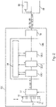
- figure 1 shows a block diagram of a position measuring device 10 according to the invention. It comprises a scanning unit 12 which is suitably designed to scan a measuring graduation on a graduation carrier 14. Graduation carrier 14 and scanning unit 12 are arranged in a known manner so as to be movable relative to one another in a measuring direction, for example by being connected to moving parts of a machine tool whose relative position to one another is to be determined.
- Both linear (length measuring devices) and rotary position measuring devices (rotary encoders or angle measuring devices) can be designed according to the invention.
- the present invention is largely independent of the physical scanning principle. Optical, magnetic, capacitive or inductive scanning can be used.
- the measuring graduation consists of an incremental graduation track 16 and a reference graduation track 17.
- the scanning of the measuring graduation 16, 17 results in scanning signals S0, S90, R, the two incremental signals S0, S90 phase-shifted by 90° from the scanning of the incremental graduation track 16, as well as a Reference signal R from the scanning of the reference graduation track 17 include.
- pure pre-processing of detector signals can take place in the scanning unit 12 to generate the scanning signals S0, S90, for example a conversion of current signals into voltage signals.
- the incremental signals S0, S90 are largely sinusoidal given a uniform movement (corresponding to a constant speed) of the measuring graduation relative to the scanning unit 12.
- the reference signal R is used to supply an absolute reference position for the relative position measurement of the incremental position measuring device 10 that is inherent to the principle.
- the reference signal R has a pulse at at least one defined position (or, in the case of an angle measuring device, at a defined angular position), which is referred to as a reference pulse.
- the scanning signals S0, S90, R are fed to a signal processing unit 20, which processes them into position signals P0, P90, PR.
- the signal processing unit 20 comprises at least one correction unit 20.1, 20.2, 20.3, three in the example shown, each suitable for correcting signal errors in at least one of the scanning signals. Specifically, it is an offset correction unit 20.1, an amplitude correction unit 20.2 and a phase correction unit 20.3.
- the offset correction unit 20.1 serves to correct a signal offset of the incremental signals S0, S90, so that the minimum and maximum values of the sinusoidal signals are arranged symmetrically around a reference potential (usually ground potential 0V). It can also be designed to set a rest potential of the reference signal R, ie the potential that the reference signal R has as long as no reference pulse occurs.
- the amplitude correction unit 20.2 serves to amplify the signal amplitudes of the incremental signals to defined values, for example to a peak-to-peak value of 1V. Amplifier components can be used for this.
- the amplitude correction unit 20.2 can also be designed to set the amplitude of the reference pulse R to a defined value.
- the phase correction unit 20.3 is suitably designed to the phase shift between the Set incremental signals, for example to 90 °, the direction of movement (direction of rotation) determines which of the signals leads or lags.
- the phase correction unit 20.3 can also be provided to set the position of the reference pulse in relation to the incremental signals, for example such that its maximum is at a position at which the incremental signals have positive values and the same instantaneous value.
- the scanning signals corrected in this way are output as position signals P0, P90, PR via a signal interface 50 to subsequent electronics 80, for example a numerical control of a machine tool.
- the position signals P0, P90, PR correspond exactly to the ideal values of the interface specification.
- the signal interface 50 can include driver modules that amplify the position signals P0, P90, PR for output to the subsequent electronics.
- the driver modules can be suitably designed to output the position signals P0, P90, PR both in the polarity generated by the signal processing unit 20 and as inverted position signals P180, P270, IPR.
- a monitoring unit 30 is arranged in the signal processing unit 20 . This is suitably designed to determine whether one of the signal errors of the scanning signals S0, S90, R corrected in the correction units 20.1, 20.2, 20.3 reaches, exceeds or falls below a limit value. If this is the case, the monitoring unit 30 switches to a signaling mode and deactivates at least the correction unit 20.1, 20.2, 20.3 corresponding to this signal error, deactivating in this exemplary embodiment meaning that the corresponding correction unit 20.1, 20.2, 20.3 is in a basic state is switched, i.e. no more correction is carried out. The consequence of this is that the position signals P0, P90, PR have at least the signal error that led to the switchover to the signaling mode.
- the amplitude correction unit 20.2 is deactivated; if the offset of one of the sampling signals S0, S90, R rises above a limit value, the offset correction unit 20.1 is deactivated, etc .
- the limit values are advantageously selected in such a way that the subsequent electronics 80 can still evaluate the position signals P0, P90, PR, i.e. that the machine on which the position measuring device 10 is operated remains functional.
- the monitoring unit 30 deactivates all the correction units 20.1, 20.2, 20.3 in such an error case, so that the scanning signals S0, S90, R are output as the position signals P0, P90, PR.
- Switching means 30.1, 30.2, 30.3 are provided for deactivating the correction units 20.1, 20.2, 20.3.
- a receiver-side monitoring unit 90 is provided on the subsequent electronics 80 side, which monitors the position signals P0, P90, PR and detects the sudden change in one or more error variables caused by the shutdown of one or more correction units 20.1, 20.2, 20.3 and displays it to an operator of the system, for example by issuing a warning message on a monitor.
- the receiver-side monitoring unit 90 can, as in figure 1 shown, be arranged within the subsequent electronics 80, but it can also be a separate device.
- the configuration of a position measuring device 10 has two effects that are relevant in practice: firstly, the subsequent electronics 80 can be signaled in this way that an imminent failure of the position measuring device 10 must be expected, or that the position measuring device 10 must be serviced in order to prevent a failure. In this case, maintenance can mean that the measuring graduation 16, 17 and/or the scanning unit 12 has to be cleaned, or that the position of the scanning unit 12 in relation to the measuring graduation 16, 17 has to be reset. Secondly, the signaling mode can be used to be able to optimally set the position of the scanning unit 12 relative to the measuring graduation 16, 17 when the position measuring device 10 is put into operation in the first place, so that position signals P0, P90, PR that are as precise as possible are obtained even without correction.
- correction units 20.1, 20.1, 20.3 were always active, a rough positioning of the scanning unit 12 relative to the measuring graduation would be sufficient to obtain usable position signals P0, P90, PR. In this case, however, it can happen that one or more of the scanning signals S0, S90, R only just keep to the prescribed limit values. An adjustment with active correction units 20.1, 20.1, 20.3 is therefore not practical.
- Switching to signaling mode can be artificially triggered by attenuating or interrupting the signals used for sampling. This can be achieved by the scanning unit 12 being so far removed from the measuring graduation 16, 17 during commissioning that one or more limit values of signal errors are reached or exceeded or fallen below. This is particularly easy to do with what are known as open length measuring devices, because here the scale (graduation carrier 14) and scanning unit 12 are usually supplied and installed separately. A further possibility is to introduce damping or interrupting means between the scanning unit 12 and the measuring graduation 16 , 17 .
- the light path between a light source and corresponding photodetectors can be interrupted by a film, etc.
- a ferromagnetic material can be introduced between the measuring graduation 16, 17 and the magnetic sensors become, etc.
- deactivated correction units 20.1, 20.2, 20.3 can only be activated again by switching the position measuring device 10 off and on again.
- figure 2 shows another position measuring device 100.
- Components that are already in connection with figure 1 have been described bear the same reference numerals.
- a signal processing unit 120 includes an offset correction unit 120.1, an amplitude correction unit 120.2 and a phase correction unit 120.3.
- the correction units 120.1, 120.2, 120.3 now signal to the monitoring unit 130 that a limit value has been reached or exceeded or fallen below. If this is the case, then the monitoring unit 130 in turn deactivates at least the correction unit 120.1, 120.2, 120.3 corresponding to this signal error or also all correction units 120.1, 120.2, 120.3. However, the deactivation does not take place by switching off or bridging the respective correction unit 120.1, 120.2, 120.3, but by disabling the correction function by storing current control parameters and thus the function of the correction unit 120.1, 120.2, 120.3 is quasi frozen. The consequence of this is that the position signals P0, P90, PR do not change immediately when the signaling mode changes, but a change can only be detected if the signal error increases further.
- signal errors can also be corrected by directly influencing the scanning unit 12.
- the signal amplitude of the scanning signals S0, S90, R can be increased by increasing the current for operating the light source. Even if the scanning signals S0, S90, R are no longer physically measurable in this case, they are still to be understood as meaning the signals that would be generated by the scanning unit 12 without the influence of the correction units 120.1, 120.2, 120.3. Of course, this also applies to the first exemplary embodiment.
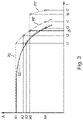
- figure 3 shows the advantages of the two exemplary embodiments based on the example of the signal curve of the amplitude value A of the incremental scanning signal S0 or of the position signal P0 over time figures 1 and 2 were explained.
- the curve drawn in broken lines adjusts the position signal P0 according to the exemplary embodiment figure 1 represents the dot-dash curve the alternative course of the position signal P0 'according to the example of figure 2 .
- the curves shown cover a period of many years.
- the scanning signal S0 (and also the position signal P0) has an initial amplitude A1.
- the amplitude decreases, in particular in the case of an optical scanning principle, as a result of a deterioration in the luminosity of the light source or as a result of continuously increasing contamination of the measuring graduation.
- the limit value A2 is the amplitude value at which the monitoring unit 90 on the receiver side detects a reduction in the amplitude on the part of the subsequent electronics 80 and generates a warning signal.
- the limit value A3 is the amplitude value which, when it is reached or undershot, the monitoring unit 30 switches the position measuring device 10, 100 to the signaling mode.
- limit value A4 is the smallest amplitude value that can still be evaluated by subsequent electronics 80 . Falling below limit value A4 leads to failure of the system in which position-measuring device 10, 100 is operated.
- the scanning signal S0 now reaches the limit value A3 and the position measuring device 10, 100 switches to the signaling mode and deactivates the amplitude correction unit 20.2 or 120.2.
- the position measuring device 10 which according to the embodiment of figure 1 is designed, to a sudden reduction in the position signal P0, which is immediately recognized because the subsequent electronics 80 falls below the limit value A2.
- the position-measuring device 10 can still be operated up to time t3, so that there is sufficient time to service or replace the position-measuring device 10 in the course of a normal maintenance interval.
- the position signal P0′ largely follows the profile of the scanning signal S0 from the point in time of the switchover and only reaches the limit value A2 at a point in time t2.
- the time span between times t2 and t4 is shorter than the time span between times t1 and t3 in the first exemplary embodiment.
- the end of the service life of the position measuring device 10 of the first exemplary embodiment is reached at time t3 earlier than the end of the service life of the position measuring device 100 of the second example.
- the correction unit 20.1, 20.2, 20.3, 120.1, 120.2, 120.3 were operated until it reached its control limit, the time between detecting an imminent malfunction and reaching the end of the service life of the position measuring device 10, 100 would be so short that a reaction in form of maintenance or replacement would no longer be possible within a standard maintenance interval.
- a further improvement of the position measuring device 100 can be achieved if, in the example of FIG figure 2 the monitoring unit 130 is additionally suitably configured, when a second limit value A5 is reached (at time t5), at least the correction unit triggering the event (in the example of figure 3 to activate the amplitude correction unit 120.2) again, specifically with a target value of the regulation, which represents a poorer signal quality of the position signals P0, P90, PR.
- the control setpoint is set to the second limit value A5, resulting in the alternative amplitude curve of the position signal P0" shown as a dotted line.
- the amplitude of the position signal P0" can be at the level of the second limit value A5 up to Reaching the control limit at time t6 are held.
- the amplitude of the position signal P0" drops rapidly and reaches the limit value A4 for safe operation of the system at point in time t7.
- the second limit value A5 can of course also be reached by monitoring the scanning signal S0.
- This method can also be used adapted to other signal errors and can also be mapped to the first exemplary embodiment.
- This procedure leads both to a longer achievable operating time of the position measuring device 100 and to increased reliability when evaluating the position signal P0" in the subsequent electronics 80, since the risk of a processing error in the subsequent electronics 80 increases the higher the amplitude of the position signal P0 " approaches the functional limit A4.
- the signal processing unit 20, 120 is advantageously at least partially in the form of a programmable module (FPGA) or an application-specific integrated circuit (ASIC). It is also advantageous to implement functions of the signal processing unit 20, 120 in whole or in part by using a microprocessor, in particular a signal processor. In addition to the functions described, the signal processing unit 20, 120 can also carry out processing steps.
- FPGA programmable module
- ASIC application-specific integrated circuit
Landscapes
- Physics & Mathematics (AREA)
- General Physics & Mathematics (AREA)
- Transmission And Conversion Of Sensor Element Output (AREA)
- Basic Packing Technique (AREA)
- Body Structure For Vehicles (AREA)
- Vehicle Body Suspensions (AREA)
Claims (7)
- Dispositif de mesure de position, comprenant un support de graduation (14) muni d'une graduation de mesure (16, 17), une unité de balayage (12), qui est disposée de manière mobile dans une direction de mesure par rapport à la graduation de mesure (16, 17), pour générer des signaux de balayage (S0, S90, R) dépendant de la position par balayage de la graduation de mesure (16, 17), une unité de traitement de signaux (20, 120) pour transformer les signaux de balayage (S0, S90, R) en signaux de position (P0, P90, PR) et une interface de signaux (50) qui est adaptée pour émettre les signaux de position (P0, P90, PR) à une électronique de suite (80),dans lequel, dans l'unité de traitement de signaux (20, 120), est agencée au moins une unité de correction (20.1, 20.2, 20.3 ; 120.1, 120.2, 120.3), qui est adaptée pour corriger au moins une erreur de signal d'au moins un signal de balayage (S0, S90, R), ainsi qu'une unité de surveillance (30, 130) qui est adaptée pour déterminer si une valeur limite de l'erreur de signal est atteinte et pour désactiver ensuite au moins l'unité de correction (20.1, 20.2, 20.3 ; 120.1, 120.2, 120.3) correspondant à ladite erreur de signal, etdans lequel l'unité de correction (20.1, 20.2, 20.3) peut être désactivée par l'unité de surveillance (30) en la déconnectant de manière à ce que le signal de balayage (S0, S90, R) soit délivré en tant que signal de position (P0, P90, PR).
- Dispositif de mesure de position, comprenant un support de graduation (14) muni d'une graduation de mesure (16, 17), une unité de balayage (12), qui est disposée de manière mobile dans une direction de mesure par rapport à la graduation de mesure (16, 17), pour générer des signaux de balayage (S0, S90, R) dépendant de la position par balayage de la graduation de mesure (16, 17), une unité de traitement de signaux (20, 120) pour transformer les signaux de balayage (S0, S90, R) en signaux de position (P0, P90, PR) et une interface de signaux (50) qui est adaptée pour émettre les signaux de position (P0, P90, PR) à une électronique de suite (80),dans lequel, dans l'unité de traitement de signaux (20, 120), est agencée au moins une unité de correction (20.1, 20.2, 20.3 ; 120.1, 120.2, 120.3), qui est adaptée pour corriger au moins une erreur de signal d'au moins un signal de balayage (S0, S90, R), ainsi qu'une unité de surveillance (30, 130) qui est adaptée pour déterminer si une valeur limite de l'erreur de signal est atteinte et pour désactiver ensuite au moins l'unité de correction (20.1, 20.2, 20.3 ; 120.1, 120.2, 120.3) correspondant à ladite erreur de signal, en particulier selon la revendication 1, etdans lequel l'unité de surveillance (30, 130) est en outre adaptée pour réactiver au moins l'unité de correction (20.1, 20.2, 20.3 ; 120.1, 120.2, 120.3) qui déclenche l'événement lorsqu'une deuxième valeur limite (A5) est atteinte et cela, en utilisant une valeur de consigne de la régulation qui est adaptée pour atteindre une moins bonne qualité de signal des signaux de position (P0, P90, PR) qu'avec la régulation jusqu'à la première valeur limite.
- Dispositif de mesure de position selon l'une des revendications précédentes, dans lequel ladite au moins une unité de correction (20.1, 20.2, 20.3 ; 120.1, 120.2, 120.3) est une unité de correction de décalage (20.1, 120.1), une unité de correction d'amplitude (20.2, 120.2) ou une unité de correction de phase (20.3, 120.3).
- Procédé de fonctionnement d'un dispositif de mesure de position, comprenant un support de graduation (14) muni d'une graduation de mesure (16, 17), une unité de balayage (12), qui est disposée de manière mobile dans une direction de mesure par rapport à la graduation de mesure (16, 17), et au moyen de laquelle des signaux de balayage (S0, S90, R) dépendant de la position sont générés par balayage de la graduation de mesure (16, 17), une unité de traitement de signaux (20, 120) dans laquelle des signaux de balayage (S0, S90, R) sont transformés en signaux de position (P0, P90, PR) et une interface de signaux (50) au moyen de laquelle les signaux de position (P0, P90, PR) sont émis à une électronique de suite (80),dans lequel, dans l'unité de traitement de signaux (20, 120), est agencée au moins une unité de correction (20.1, 20.2, 20.3 ; 120.1, 120.2, 120.3), au moyen de laquelle au moins une erreur de signal d'au moins un signal de balayage (S0, S90, R) est corrigée, ainsi qu'une unité de surveillance (30, 130) au moyen de laquelle il est déterminé si une valeur limite de l'erreur de signal est atteinte et ensuite au moins l'unité de correction (20.1, 20.2, 20.3 ; 120.1, 120.2, 120.3) correspondant à ladite erreur de signal est désactivée, etdans lequel l'unité de surveillance (30) désactive l'unité de correction (20.1, 20.2, 20.3) en la déconnectant de manière à ce que le signal de balayage (S0, S90, R) soit émis en tant que signal de position (P0, P90, PR).
- Procédé de fonctionnement d'un dispositif de mesure de position, comprenant un support de graduation (14) muni d'une graduation de mesure (16, 17), une unité de balayage (12), qui est disposée de manière mobile dans une direction de mesure par rapport à la graduation de mesure (16, 17), et au moyen de laquelle des signaux de balayage (S0, S90, R) dépendant de la position sont générés par balayage de la graduation de mesure (16, 17), une unité de traitement de signaux (20, 120) dans laquelle des signaux de balayage (S0, S90, R) sont transformés en signaux de position (P0, P90, PR) et une interface de signaux (50) au moyen de laquelle les signaux de position (P0, P90, PR) sont émis à une électronique de suite (80),dans lequel, dans l'unité de traitement de signaux (20, 120), est agencée au moins une unité de correction (20.1, 20.2, 20.3 ; 120.1, 120.2, 120.3), au moyen de laquelle au moins une erreur de signal d'au moins un signal de balayage (S0, S90, R) est corrigée, ainsi qu'une unité de surveillance (30, 130) au moyen de laquelle il est déterminé si une valeur limite de l'erreur de signal est atteinte et ensuite au moins l'unité de correction (20.1, 20.2, 20.3 ; 120.1, 120.2, 120.3) correspondant à ladite erreur de signal est désactivée, en particulier selon la revendication 4, etdans lequel au moins l'unité de correction (20.1, 20.2, 20.3 ; 120.1, 120.2, 120.3) qui déclenche l'événement est réactivée par l'unité de surveillance (30, 130) lorsqu'une deuxième valeur limite (A5) est atteinte et cela, en utilisant une valeur de consigne de la régulation qui est adaptée pour atteindre une moins bonne qualité de signal des signaux de position (P0, P90, PR) qu'avec la régulation jusqu'à la première valeur limite.
- Procédé selon l'une des revendications 4 ou 5, dans lequel ladite au moins une unité de correction désactivée (20.1, 20.2, 20.3 ; 120.1, 120.2, 120.3) est réactivée par déconnexion et reconnexion du dispositif de mesure de position (10, 100).
- Système de transmission de signaux comportant un dispositif de mesure de position (10, 100) selon l'une des revendications 1 à 3, relié à une électronique de suite (80), dans lequel une unité de surveillance (90) côté récepteur est disposée du côté de l'électronique de suite (80), qui est adaptée pour déterminer si une valeur limite d'au moins un signal de position (P0, P90, PR) est atteinte.
Applications Claiming Priority (1)
| Application Number | Priority Date | Filing Date | Title |
|---|---|---|---|
| DE102016214456.1A DE102016214456A1 (de) | 2016-08-04 | 2016-08-04 | Positionsmesseinrichtung und Verfahren zum Betreiben einer Positionsmesseinrichtung |
Publications (3)
| Publication Number | Publication Date |
|---|---|
| EP3279614A1 EP3279614A1 (fr) | 2018-02-07 |
| EP3279614B1 EP3279614B1 (fr) | 2019-08-28 |
| EP3279614B2 true EP3279614B2 (fr) | 2022-10-12 |
Family
ID=58669736
Family Applications (1)
| Application Number | Title | Priority Date | Filing Date |
|---|---|---|---|
| EP17169506.7A Active EP3279614B2 (fr) | 2016-08-04 | 2017-05-04 | Dispositif de mesure de position et son procédé de fonctionnement |
Country Status (6)
| Country | Link |
|---|---|
| US (1) | US10260908B2 (fr) |
| EP (1) | EP3279614B2 (fr) |
| JP (1) | JP7017878B2 (fr) |
| CN (1) | CN107687829B (fr) |
| DE (1) | DE102016214456A1 (fr) |
| ES (1) | ES2759440T5 (fr) |
Families Citing this family (4)
| Publication number | Priority date | Publication date | Assignee | Title |
|---|---|---|---|---|
| DE102018209136A1 (de) * | 2018-06-08 | 2019-12-12 | Dr. Johannes Heidenhain Gmbh | Positionsmesseinrichtung und Verfahren zum Betreiben einer Positionsmesseinrichtung |
| CN113138417B (zh) * | 2020-01-20 | 2023-11-28 | 中国石油天然气集团有限公司 | 一种基于力信号反馈的扫描信号自动校正方法及装置 |
| US11550001B2 (en) * | 2020-02-12 | 2023-01-10 | Infineon Technologies Ag | Safety mechanism monitoring of autocalibrated compensation parameters |
| US20220314963A1 (en) * | 2021-03-31 | 2022-10-06 | Sensata Technologies, Inc. | Accurate error estimation in e-motor sensors |
Citations (3)
| Publication number | Priority date | Publication date | Assignee | Title |
|---|---|---|---|---|
| DE4400482A1 (de) † | 1993-04-23 | 1994-10-27 | Bosch Gmbh Robert | Korrekturverfahren zwischen dem elektrischen Phasenwinkel und dem mechanischen Abtriebswinkel eines Schrittmotors |
| DE19853452C1 (de) † | 1998-11-19 | 2000-02-03 | Daniel Bonk | Robotervorrichtung |
| WO2015004472A2 (fr) † | 2013-07-12 | 2015-01-15 | Trw Limited | Encodeur rotatif |
Family Cites Families (27)
| Publication number | Priority date | Publication date | Assignee | Title |
|---|---|---|---|---|
| AT396631B (de) * | 1984-07-06 | 1993-10-25 | Rsf Elektronik Gmbh | Inkrementales messsystem |
| ES2124407T3 (es) * | 1994-01-11 | 1999-02-01 | Bosch Gmbh Robert | Procedimiento de correccion entre el angulo de fase electrico y el angulo de salida mecanico de un motor paso a paso. |
| DE19521252C5 (de) | 1995-06-10 | 2011-05-05 | Dr. Johannes Heidenhain Gmbh | Anordnung zum Übertragen von Positionsmeßsignalen |
| WO1999042790A1 (fr) * | 1998-02-21 | 1999-08-26 | Dr. Johannes Heidenhain Gmbh | Procede permettant de faire fonctionner un systeme de mesure de position et systeme de mesure de position approprie |
| JP4582955B2 (ja) | 2001-05-30 | 2010-11-17 | 日本電産サンキョー株式会社 | エンコーダ |
| CN1250933C (zh) * | 2001-09-04 | 2006-04-12 | 约翰尼斯海登海恩博士股份有限公司 | 位置测量装置及运行位置测量装置的方法 |
| DE10201496A1 (de) * | 2002-01-17 | 2003-07-31 | Heidenhain Gmbh Dr Johannes | Maßstab und Positionsmesseinrichtung zur absoluten Positionsbestimmung |
| US7129858B2 (en) * | 2003-10-10 | 2006-10-31 | Hewlett-Packard Development Company, L.P. | Encoding system |
| JP4518786B2 (ja) | 2003-12-12 | 2010-08-04 | 株式会社ミツトヨ | 内挿誤差補正方法及び装置 |
| DE102006007871A1 (de) * | 2005-03-03 | 2006-09-21 | Continental Teves Ag & Co. Ohg | Sensor und Verfahren zur Erfaasung von Ortsverschiebungen und Drehbewegungen |
| DE102005029553A1 (de) * | 2005-06-25 | 2007-01-04 | Dr. Johannes Heidenhain Gmbh | Positionsmesseinrichtung und Verfahren zur Kontrolle von Abtastsignalen der Positionsmesseinrichtung |
| JP4277887B2 (ja) | 2006-08-22 | 2009-06-10 | パナソニック株式会社 | エンコーダ信号の補正回路 |
| DE102007023300A1 (de) * | 2007-05-16 | 2008-11-20 | Dr. Johannes Heidenhain Gmbh | Positionsmesseinrichtung und Anordnung derselben |
| DE102007061287A1 (de) * | 2007-12-19 | 2009-06-25 | Dr. Johannes Heidenhain Gmbh | Positionsmesseinrichtung und Verfahren zur absoluten Positionsbestimmung |
| DE102008022027A1 (de) * | 2008-05-02 | 2009-11-05 | Dr. Johannes Heidenhain Gmbh | Positionsmesseinrichtung |
| US8886471B2 (en) * | 2008-06-26 | 2014-11-11 | Infineon Technologies Ag | Rotation sensing method and system |
| DE102008049140A1 (de) | 2008-09-26 | 2010-04-01 | Dr. Johannes Heidenhain Gmbh | Anordnung und Verfahren zur Erzeugung eines Referenzimpulses für ein Positionsmessgerät |
| DE102011075286A1 (de) * | 2011-05-05 | 2012-11-08 | Dr. Johannes Heidenhain Gmbh | Optische Positionsmesseinrichtung |
| DE102011079961A1 (de) | 2011-07-28 | 2013-01-31 | Dr. Johannes Heidenhain Gmbh | Vorrichtung und Verfahren zur Winkelmessung |
| JP6057530B2 (ja) * | 2012-04-06 | 2017-01-11 | ハイデンハイン株式会社 | エンコーダの出力信号監視システムおよびエンコーダの出力信号監視方法 |
| JP2016001103A (ja) | 2012-10-18 | 2016-01-07 | 三菱電機株式会社 | 位置検出装置 |
| JP6149254B2 (ja) | 2013-06-20 | 2017-06-21 | パナソニックIpマネジメント株式会社 | モータ位置検出器 |
| DE102014209004A1 (de) * | 2014-05-13 | 2015-11-19 | Dr. Johannes Heidenhain Gmbh | Positionsmesseinrichtung |
| FR3033051B1 (fr) * | 2015-02-24 | 2017-02-10 | Continental Automotive France | Procede et dispositif de traitement d'un signal produit par un capteur de rotation d'une cible tournante |
| ES2742705T3 (es) * | 2015-07-30 | 2020-02-17 | Heidenhain Gmbh Dr Johannes | Dispositivo de medición de posición |
| US10184807B2 (en) * | 2016-09-26 | 2019-01-22 | Infineon Technologies Ag | True-power-on and diagnostic-capable incremental interface for angular sensors |
| JP6875923B2 (ja) * | 2017-04-27 | 2021-05-26 | Dmg森精機株式会社 | スケール装置および二軸変位検出装置 |
-
2016
- 2016-08-04 DE DE102016214456.1A patent/DE102016214456A1/de not_active Withdrawn
-
2017
- 2017-05-04 ES ES17169506T patent/ES2759440T5/es active Active
- 2017-05-04 EP EP17169506.7A patent/EP3279614B2/fr active Active
- 2017-06-19 CN CN201710466577.5A patent/CN107687829B/zh active Active
- 2017-08-02 US US15/667,539 patent/US10260908B2/en active Active
- 2017-08-03 JP JP2017150613A patent/JP7017878B2/ja active Active
Patent Citations (3)
| Publication number | Priority date | Publication date | Assignee | Title |
|---|---|---|---|---|
| DE4400482A1 (de) † | 1993-04-23 | 1994-10-27 | Bosch Gmbh Robert | Korrekturverfahren zwischen dem elektrischen Phasenwinkel und dem mechanischen Abtriebswinkel eines Schrittmotors |
| DE19853452C1 (de) † | 1998-11-19 | 2000-02-03 | Daniel Bonk | Robotervorrichtung |
| WO2015004472A2 (fr) † | 2013-07-12 | 2015-01-15 | Trw Limited | Encodeur rotatif |
Non-Patent Citations (1)
| Title |
|---|
| ANONYMOUS: "iC-TW8 16-BIT SIN/COS Interpolator with Auto-Calibration", IC HAUS, 3 August 2015 (2015-08-03), pages 1 - 67, Retrieved from the Internet <URL:https://web.archive.org/web/20150803194954/http:/www.ichaus.de/product/iCTW8> † |
Also Published As
| Publication number | Publication date |
|---|---|
| CN107687829A (zh) | 2018-02-13 |
| US10260908B2 (en) | 2019-04-16 |
| ES2759440T3 (es) | 2020-05-11 |
| CN107687829B (zh) | 2022-07-08 |
| EP3279614A1 (fr) | 2018-02-07 |
| JP7017878B2 (ja) | 2022-02-09 |
| EP3279614B1 (fr) | 2019-08-28 |
| DE102016214456A1 (de) | 2018-02-08 |
| ES2759440T5 (es) | 2023-03-06 |
| US20180038715A1 (en) | 2018-02-08 |
| JP2018021913A (ja) | 2018-02-08 |
Similar Documents
| Publication | Publication Date | Title |
|---|---|---|
| EP3279614B2 (fr) | Dispositif de mesure de position et son procédé de fonctionnement | |
| EP2283322B1 (fr) | Procédé et circuiterie de surveillance d'un capteur d'angle de rotation | |
| DE102006003362A1 (de) | Koordinatenmessgerät und Verfahren zum Betreiben eines Koordinatenmessgeräts | |
| EP2504900B1 (fr) | Circuit de sécurité et méthode pour une surveillance sûre d'un mouvement | |
| EP2274656A1 (fr) | Appareil de mesure comportant une électronique de mesure et d'exploitation pour le contrôle d'un signal de mesure | |
| DE102017219448B4 (de) | Signalprotokoll-Störungserkennungssystem und -verfahren | |
| DE102006009181A1 (de) | Sichere Überwachung der Geschwindigkeit bei Koordinatenmessgeräten | |
| DE4330823A1 (de) | Antriebsvorrichtung mit einer Sicherheitseinrichtung für den Sonderbetrieb | |
| EP1387463B1 (fr) | Procédé et dispositif pour reconnaitre avec certitude la position d'un interrupteur rotatif | |
| EP0204897B1 (fr) | Méthode et dispositif pour contrôler le facteur d'utilisation des impulsions d'un signal électrique | |
| EP1313664A1 (fr) | Systeme de securite redondant d'un vehicule | |
| EP2017678A1 (fr) | Procédé et dispositif de transmission de signaux d'un dispositif de mesure de position vers une unité d'évaluation | |
| DE102010051873B4 (de) | Integrierte Schaltungsanordnung und Verfahren zur Signalüberwachung | |
| EP3577422B1 (fr) | Procédé et dispositif pour surveiller les signaux de voie d'un capteur de changement de position | |
| EP1166047B1 (fr) | Procede et circuit pour la correction de signaux periodiques d'un systeme de mesure de position incrementiel | |
| DE102004019284A1 (de) | Vorrichtung zum Betrieb eines Synchronmotors | |
| EP3296184B1 (fr) | Dispositif et procede destine a surveiller l'arret de vehicules, en particulier des vehicules sur rails | |
| EP3540380B1 (fr) | Dispositif de surveillance pour une installation | |
| EP2603772B1 (fr) | Circuiterie de régulation et de surveillance d'un courant de signal et transducteur de mesure comprenant une telle circuiterie | |
| EP3851806A1 (fr) | Dispositif capteur et procédé de fonctionnement d'un dispositif capteur | |
| EP3483675A1 (fr) | Circuit d'entrée permettant une lecture protégée contre les erreurs d'un signal d'entrée analogique | |
| DE102011122363A1 (de) | Elektrische Ansteuerung für Elektromagnete | |
| EP2518464A2 (fr) | Capteur de pression à sécurité intrinsèque | |
| DE102005005653B4 (de) | Vorrichtung zum Einstellen und Überwachen des Drucks in einem Fluid | |
| WO2019038238A1 (fr) | Dispositif et procédé de transmission d'une grandeur physique à l'aide de signaux analogiques destinés à une commande de véhicule |
Legal Events
| Date | Code | Title | Description |
|---|---|---|---|
| PUAI | Public reference made under article 153(3) epc to a published international application that has entered the european phase |
Free format text: ORIGINAL CODE: 0009012 |
|
| STAA | Information on the status of an ep patent application or granted ep patent |
Free format text: STATUS: REQUEST FOR EXAMINATION WAS MADE |
|
| 17P | Request for examination filed |
Effective date: 20170504 |
|
| AK | Designated contracting states |
Kind code of ref document: A1 Designated state(s): AL AT BE BG CH CY CZ DE DK EE ES FI FR GB GR HR HU IE IS IT LI LT LU LV MC MK MT NL NO PL PT RO RS SE SI SK SM TR |
|
| AX | Request for extension of the european patent |
Extension state: BA ME |
|
| STAA | Information on the status of an ep patent application or granted ep patent |
Free format text: STATUS: EXAMINATION IS IN PROGRESS |
|
| 17Q | First examination report despatched |
Effective date: 20180207 |
|
| RBV | Designated contracting states (corrected) |
Designated state(s): AL AT BE BG CH CY CZ DE DK EE ES FI FR GB GR HR HU IE IS IT LI LT LU LV MC MK MT NL NO PL PT RO RS SE SI SK SM TR |
|
| GRAP | Despatch of communication of intention to grant a patent |
Free format text: ORIGINAL CODE: EPIDOSNIGR1 |
|
| STAA | Information on the status of an ep patent application or granted ep patent |
Free format text: STATUS: GRANT OF PATENT IS INTENDED |
|
| RIC1 | Information provided on ipc code assigned before grant |
Ipc: G01D 3/08 20060101ALI20190417BHEP Ipc: G08C 15/06 20060101ALI20190417BHEP Ipc: G01D 5/244 20060101AFI20190417BHEP Ipc: G01D 5/245 20060101ALI20190417BHEP |
|
| INTG | Intention to grant announced |
Effective date: 20190516 |
|
| GRAS | Grant fee paid |
Free format text: ORIGINAL CODE: EPIDOSNIGR3 |
|
| GRAA | (expected) grant |
Free format text: ORIGINAL CODE: 0009210 |
|
| STAA | Information on the status of an ep patent application or granted ep patent |
Free format text: STATUS: THE PATENT HAS BEEN GRANTED |
|
| AK | Designated contracting states |
Kind code of ref document: B1 Designated state(s): AL AT BE BG CH CY CZ DE DK EE ES FI FR GB GR HR HU IE IS IT LI LT LU LV MC MK MT NL NO PL PT RO RS SE SI SK SM TR |
|
| REG | Reference to a national code |
Ref country code: GB Ref legal event code: FG4D Free format text: NOT ENGLISH |
|
| REG | Reference to a national code |
Ref country code: CH Ref legal event code: EP |
|
| REG | Reference to a national code |
Ref country code: CH Ref legal event code: NV Representative=s name: ICB INGENIEURS CONSEILS EN BREVETS SA, CH |
|
| REG | Reference to a national code |
Ref country code: AT Ref legal event code: REF Ref document number: 1172969 Country of ref document: AT Kind code of ref document: T Effective date: 20190915 |
|
| REG | Reference to a national code |
Ref country code: IE Ref legal event code: FG4D Free format text: LANGUAGE OF EP DOCUMENT: GERMAN |
|
| REG | Reference to a national code |
Ref country code: DE Ref legal event code: R096 Ref document number: 502017002124 Country of ref document: DE |
|
| REG | Reference to a national code |
Ref country code: NL Ref legal event code: MP Effective date: 20190828 |
|
| REG | Reference to a national code |
Ref country code: LT Ref legal event code: MG4D |
|
| PG25 | Lapsed in a contracting state [announced via postgrant information from national office to epo] |
Ref country code: HR Free format text: LAPSE BECAUSE OF FAILURE TO SUBMIT A TRANSLATION OF THE DESCRIPTION OR TO PAY THE FEE WITHIN THE PRESCRIBED TIME-LIMIT Effective date: 20190828 Ref country code: PT Free format text: LAPSE BECAUSE OF FAILURE TO SUBMIT A TRANSLATION OF THE DESCRIPTION OR TO PAY THE FEE WITHIN THE PRESCRIBED TIME-LIMIT Effective date: 20191230 Ref country code: NO Free format text: LAPSE BECAUSE OF FAILURE TO SUBMIT A TRANSLATION OF THE DESCRIPTION OR TO PAY THE FEE WITHIN THE PRESCRIBED TIME-LIMIT Effective date: 20191128 Ref country code: SE Free format text: LAPSE BECAUSE OF FAILURE TO SUBMIT A TRANSLATION OF THE DESCRIPTION OR TO PAY THE FEE WITHIN THE PRESCRIBED TIME-LIMIT Effective date: 20190828 Ref country code: FI Free format text: LAPSE BECAUSE OF FAILURE TO SUBMIT A TRANSLATION OF THE DESCRIPTION OR TO PAY THE FEE WITHIN THE PRESCRIBED TIME-LIMIT Effective date: 20190828 Ref country code: BG Free format text: LAPSE BECAUSE OF FAILURE TO SUBMIT A TRANSLATION OF THE DESCRIPTION OR TO PAY THE FEE WITHIN THE PRESCRIBED TIME-LIMIT Effective date: 20191128 Ref country code: NL Free format text: LAPSE BECAUSE OF FAILURE TO SUBMIT A TRANSLATION OF THE DESCRIPTION OR TO PAY THE FEE WITHIN THE PRESCRIBED TIME-LIMIT Effective date: 20190828 Ref country code: LT Free format text: LAPSE BECAUSE OF FAILURE TO SUBMIT A TRANSLATION OF THE DESCRIPTION OR TO PAY THE FEE WITHIN THE PRESCRIBED TIME-LIMIT Effective date: 20190828 |
|
| PG25 | Lapsed in a contracting state [announced via postgrant information from national office to epo] |
Ref country code: IS Free format text: LAPSE BECAUSE OF FAILURE TO SUBMIT A TRANSLATION OF THE DESCRIPTION OR TO PAY THE FEE WITHIN THE PRESCRIBED TIME-LIMIT Effective date: 20191228 Ref country code: GR Free format text: LAPSE BECAUSE OF FAILURE TO SUBMIT A TRANSLATION OF THE DESCRIPTION OR TO PAY THE FEE WITHIN THE PRESCRIBED TIME-LIMIT Effective date: 20191129 Ref country code: RS Free format text: LAPSE BECAUSE OF FAILURE TO SUBMIT A TRANSLATION OF THE DESCRIPTION OR TO PAY THE FEE WITHIN THE PRESCRIBED TIME-LIMIT Effective date: 20190828 Ref country code: AL Free format text: LAPSE BECAUSE OF FAILURE TO SUBMIT A TRANSLATION OF THE DESCRIPTION OR TO PAY THE FEE WITHIN THE PRESCRIBED TIME-LIMIT Effective date: 20190828 Ref country code: LV Free format text: LAPSE BECAUSE OF FAILURE TO SUBMIT A TRANSLATION OF THE DESCRIPTION OR TO PAY THE FEE WITHIN THE PRESCRIBED TIME-LIMIT Effective date: 20190828 |
|
| PG25 | Lapsed in a contracting state [announced via postgrant information from national office to epo] |
Ref country code: TR Free format text: LAPSE BECAUSE OF FAILURE TO SUBMIT A TRANSLATION OF THE DESCRIPTION OR TO PAY THE FEE WITHIN THE PRESCRIBED TIME-LIMIT Effective date: 20190828 |
|
| PG25 | Lapsed in a contracting state [announced via postgrant information from national office to epo] |
Ref country code: DK Free format text: LAPSE BECAUSE OF FAILURE TO SUBMIT A TRANSLATION OF THE DESCRIPTION OR TO PAY THE FEE WITHIN THE PRESCRIBED TIME-LIMIT Effective date: 20190828 Ref country code: PL Free format text: LAPSE BECAUSE OF FAILURE TO SUBMIT A TRANSLATION OF THE DESCRIPTION OR TO PAY THE FEE WITHIN THE PRESCRIBED TIME-LIMIT Effective date: 20190828 Ref country code: RO Free format text: LAPSE BECAUSE OF FAILURE TO SUBMIT A TRANSLATION OF THE DESCRIPTION OR TO PAY THE FEE WITHIN THE PRESCRIBED TIME-LIMIT Effective date: 20190828 Ref country code: EE Free format text: LAPSE BECAUSE OF FAILURE TO SUBMIT A TRANSLATION OF THE DESCRIPTION OR TO PAY THE FEE WITHIN THE PRESCRIBED TIME-LIMIT Effective date: 20190828 |
|
| REG | Reference to a national code |
Ref country code: ES Ref legal event code: FG2A Ref document number: 2759440 Country of ref document: ES Kind code of ref document: T3 Effective date: 20200511 |
|
| REG | Reference to a national code |
Ref country code: DE Ref legal event code: R026 Ref document number: 502017002124 Country of ref document: DE |
|
| PG25 | Lapsed in a contracting state [announced via postgrant information from national office to epo] |
Ref country code: SM Free format text: LAPSE BECAUSE OF FAILURE TO SUBMIT A TRANSLATION OF THE DESCRIPTION OR TO PAY THE FEE WITHIN THE PRESCRIBED TIME-LIMIT Effective date: 20190828 Ref country code: IS Free format text: LAPSE BECAUSE OF FAILURE TO SUBMIT A TRANSLATION OF THE DESCRIPTION OR TO PAY THE FEE WITHIN THE PRESCRIBED TIME-LIMIT Effective date: 20200224 Ref country code: SK Free format text: LAPSE BECAUSE OF FAILURE TO SUBMIT A TRANSLATION OF THE DESCRIPTION OR TO PAY THE FEE WITHIN THE PRESCRIBED TIME-LIMIT Effective date: 20190828 |
|
| PLBI | Opposition filed |
Free format text: ORIGINAL CODE: 0009260 |
|
| PLAX | Notice of opposition and request to file observation + time limit sent |
Free format text: ORIGINAL CODE: EPIDOSNOBS2 |
|
| 26 | Opposition filed |
Opponent name: BAUMER INNOTEC AG Effective date: 20200520 |
|
| PG2D | Information on lapse in contracting state deleted |
Ref country code: IS |
|
| PG25 | Lapsed in a contracting state [announced via postgrant information from national office to epo] |
Ref country code: SI Free format text: LAPSE BECAUSE OF FAILURE TO SUBMIT A TRANSLATION OF THE DESCRIPTION OR TO PAY THE FEE WITHIN THE PRESCRIBED TIME-LIMIT Effective date: 20190828 |
|
| PLBB | Reply of patent proprietor to notice(s) of opposition received |
Free format text: ORIGINAL CODE: EPIDOSNOBS3 |
|
| PG25 | Lapsed in a contracting state [announced via postgrant information from national office to epo] |
Ref country code: MC Free format text: LAPSE BECAUSE OF FAILURE TO SUBMIT A TRANSLATION OF THE DESCRIPTION OR TO PAY THE FEE WITHIN THE PRESCRIBED TIME-LIMIT Effective date: 20190828 |
|
| REG | Reference to a national code |
Ref country code: BE Ref legal event code: MM Effective date: 20200531 |
|
| PG25 | Lapsed in a contracting state [announced via postgrant information from national office to epo] |
Ref country code: LU Free format text: LAPSE BECAUSE OF NON-PAYMENT OF DUE FEES Effective date: 20200504 |
|
| PG25 | Lapsed in a contracting state [announced via postgrant information from national office to epo] |
Ref country code: FR Free format text: LAPSE BECAUSE OF NON-PAYMENT OF DUE FEES Effective date: 20200531 Ref country code: IE Free format text: LAPSE BECAUSE OF NON-PAYMENT OF DUE FEES Effective date: 20200504 |
|
| PG25 | Lapsed in a contracting state [announced via postgrant information from national office to epo] |
Ref country code: BE Free format text: LAPSE BECAUSE OF NON-PAYMENT OF DUE FEES Effective date: 20200531 |
|
| PLAB | Opposition data, opponent's data or that of the opponent's representative modified |
Free format text: ORIGINAL CODE: 0009299OPPO |
|
| R26 | Opposition filed (corrected) |
Opponent name: BAUMER INNOTEC AG Effective date: 20200520 |
|
| APBM | Appeal reference recorded |
Free format text: ORIGINAL CODE: EPIDOSNREFNO |
|
| APBP | Date of receipt of notice of appeal recorded |
Free format text: ORIGINAL CODE: EPIDOSNNOA2O |
|
| APAH | Appeal reference modified |
Free format text: ORIGINAL CODE: EPIDOSCREFNO |
|
| APBU | Appeal procedure closed |
Free format text: ORIGINAL CODE: EPIDOSNNOA9O |
|
| PG25 | Lapsed in a contracting state [announced via postgrant information from national office to epo] |
Ref country code: MT Free format text: LAPSE BECAUSE OF FAILURE TO SUBMIT A TRANSLATION OF THE DESCRIPTION OR TO PAY THE FEE WITHIN THE PRESCRIBED TIME-LIMIT Effective date: 20190828 Ref country code: CY Free format text: LAPSE BECAUSE OF FAILURE TO SUBMIT A TRANSLATION OF THE DESCRIPTION OR TO PAY THE FEE WITHIN THE PRESCRIBED TIME-LIMIT Effective date: 20190828 |
|
| PG25 | Lapsed in a contracting state [announced via postgrant information from national office to epo] |
Ref country code: MK Free format text: LAPSE BECAUSE OF FAILURE TO SUBMIT A TRANSLATION OF THE DESCRIPTION OR TO PAY THE FEE WITHIN THE PRESCRIBED TIME-LIMIT Effective date: 20190828 |
|
| PUAH | Patent maintained in amended form |
Free format text: ORIGINAL CODE: 0009272 |
|
| STAA | Information on the status of an ep patent application or granted ep patent |
Free format text: STATUS: PATENT MAINTAINED AS AMENDED |
|
| 27A | Patent maintained in amended form |
Effective date: 20221012 |
|
| AK | Designated contracting states |
Kind code of ref document: B2 Designated state(s): AL AT BE BG CH CY CZ DE DK EE ES FI FR GB GR HR HU IE IS IT LI LT LU LV MC MK MT NL NO PL PT RO RS SE SI SK SM TR |
|
| REG | Reference to a national code |
Ref country code: DE Ref legal event code: R102 Ref document number: 502017002124 Country of ref document: DE |
|
| REG | Reference to a national code |
Ref country code: ES Ref legal event code: DC2A Ref document number: 2759440 Country of ref document: ES Kind code of ref document: T5 Effective date: 20230306 |
|
| REG | Reference to a national code |
Ref country code: AT Ref legal event code: MM01 Ref document number: 1172969 Country of ref document: AT Kind code of ref document: T Effective date: 20220504 |
|
| PG25 | Lapsed in a contracting state [announced via postgrant information from national office to epo] |
Ref country code: AT Free format text: LAPSE BECAUSE OF NON-PAYMENT OF DUE FEES Effective date: 20220504 |
|
| PGFP | Annual fee paid to national office [announced via postgrant information from national office to epo] |
Ref country code: IT Payment date: 20230526 Year of fee payment: 7 Ref country code: DE Payment date: 20220620 Year of fee payment: 7 Ref country code: CZ Payment date: 20230425 Year of fee payment: 7 Ref country code: CH Payment date: 20230602 Year of fee payment: 7 |
|
| PGFP | Annual fee paid to national office [announced via postgrant information from national office to epo] |
Ref country code: GB Payment date: 20230524 Year of fee payment: 7 Ref country code: ES Payment date: 20230725 Year of fee payment: 7 |