EP3279477B1 - Verdrängerpumpe mit laufschaufelrotor - Google Patents
Verdrängerpumpe mit laufschaufelrotor Download PDFInfo
- Publication number
- EP3279477B1 EP3279477B1 EP17184197.6A EP17184197A EP3279477B1 EP 3279477 B1 EP3279477 B1 EP 3279477B1 EP 17184197 A EP17184197 A EP 17184197A EP 3279477 B1 EP3279477 B1 EP 3279477B1
- Authority
- EP
- European Patent Office
- Prior art keywords
- channel
- rotor
- fluid
- pump according
- radially
- Prior art date
- Legal status (The legal status is an assumption and is not a legal conclusion. Google has not performed a legal analysis and makes no representation as to the accuracy of the status listed.)
- Active
Links
Images


Classifications
-
- F—MECHANICAL ENGINEERING; LIGHTING; HEATING; WEAPONS; BLASTING
- F04—POSITIVE - DISPLACEMENT MACHINES FOR LIQUIDS; PUMPS FOR LIQUIDS OR ELASTIC FLUIDS
- F04C—ROTARY-PISTON, OR OSCILLATING-PISTON, POSITIVE-DISPLACEMENT MACHINES FOR LIQUIDS; ROTARY-PISTON, OR OSCILLATING-PISTON, POSITIVE-DISPLACEMENT PUMPS
- F04C14/00—Control of, monitoring of, or safety arrangements for, machines, pumps or pumping installations
- F04C14/18—Control of, monitoring of, or safety arrangements for, machines, pumps or pumping installations characterised by varying the volume of the working chamber
- F04C14/22—Control of, monitoring of, or safety arrangements for, machines, pumps or pumping installations characterised by varying the volume of the working chamber by changing the eccentricity between cooperating members
- F04C14/223—Control of, monitoring of, or safety arrangements for, machines, pumps or pumping installations characterised by varying the volume of the working chamber by changing the eccentricity between cooperating members using a movable cam
- F04C14/226—Control of, monitoring of, or safety arrangements for, machines, pumps or pumping installations characterised by varying the volume of the working chamber by changing the eccentricity between cooperating members using a movable cam by pivoting the cam around an eccentric axis
-
- F—MECHANICAL ENGINEERING; LIGHTING; HEATING; WEAPONS; BLASTING
- F04—POSITIVE - DISPLACEMENT MACHINES FOR LIQUIDS; PUMPS FOR LIQUIDS OR ELASTIC FLUIDS
- F04C—ROTARY-PISTON, OR OSCILLATING-PISTON, POSITIVE-DISPLACEMENT MACHINES FOR LIQUIDS; ROTARY-PISTON, OR OSCILLATING-PISTON, POSITIVE-DISPLACEMENT PUMPS
- F04C2/00—Rotary-piston machines or pumps
- F04C2/30—Rotary-piston machines or pumps having the characteristics covered by two or more groups F04C2/02, F04C2/08, F04C2/22, F04C2/24 or having the characteristics covered by one of these groups together with some other type of movement between co-operating members
- F04C2/34—Rotary-piston machines or pumps having the characteristics covered by two or more groups F04C2/02, F04C2/08, F04C2/22, F04C2/24 or having the characteristics covered by one of these groups together with some other type of movement between co-operating members having the movement defined in groups F04C2/08 or F04C2/22 and relative reciprocation between the co-operating members
- F04C2/344—Rotary-piston machines or pumps having the characteristics covered by two or more groups F04C2/02, F04C2/08, F04C2/22, F04C2/24 or having the characteristics covered by one of these groups together with some other type of movement between co-operating members having the movement defined in groups F04C2/08 or F04C2/22 and relative reciprocation between the co-operating members with vanes reciprocating with respect to the inner member
- F04C2/3441—Rotary-piston machines or pumps having the characteristics covered by two or more groups F04C2/02, F04C2/08, F04C2/22, F04C2/24 or having the characteristics covered by one of these groups together with some other type of movement between co-operating members having the movement defined in groups F04C2/08 or F04C2/22 and relative reciprocation between the co-operating members with vanes reciprocating with respect to the inner member the inner and outer member being in contact along one line or continuous surface substantially parallel to the axis of rotation
- F04C2/3442—Rotary-piston machines or pumps having the characteristics covered by two or more groups F04C2/02, F04C2/08, F04C2/22, F04C2/24 or having the characteristics covered by one of these groups together with some other type of movement between co-operating members having the movement defined in groups F04C2/08 or F04C2/22 and relative reciprocation between the co-operating members with vanes reciprocating with respect to the inner member the inner and outer member being in contact along one line or continuous surface substantially parallel to the axis of rotation the surfaces of the inner and outer member, forming the working space, being surfaces of revolution
-
- F—MECHANICAL ENGINEERING; LIGHTING; HEATING; WEAPONS; BLASTING
- F04—POSITIVE - DISPLACEMENT MACHINES FOR LIQUIDS; PUMPS FOR LIQUIDS OR ELASTIC FLUIDS
- F04C—ROTARY-PISTON, OR OSCILLATING-PISTON, POSITIVE-DISPLACEMENT MACHINES FOR LIQUIDS; ROTARY-PISTON, OR OSCILLATING-PISTON, POSITIVE-DISPLACEMENT PUMPS
- F04C2/00—Rotary-piston machines or pumps
- F04C2/30—Rotary-piston machines or pumps having the characteristics covered by two or more groups F04C2/02, F04C2/08, F04C2/22, F04C2/24 or having the characteristics covered by one of these groups together with some other type of movement between co-operating members
- F04C2/34—Rotary-piston machines or pumps having the characteristics covered by two or more groups F04C2/02, F04C2/08, F04C2/22, F04C2/24 or having the characteristics covered by one of these groups together with some other type of movement between co-operating members having the movement defined in groups F04C2/08 or F04C2/22 and relative reciprocation between the co-operating members
- F04C2/344—Rotary-piston machines or pumps having the characteristics covered by two or more groups F04C2/02, F04C2/08, F04C2/22, F04C2/24 or having the characteristics covered by one of these groups together with some other type of movement between co-operating members having the movement defined in groups F04C2/08 or F04C2/22 and relative reciprocation between the co-operating members with vanes reciprocating with respect to the inner member
- F04C2/3446—Rotary-piston machines or pumps having the characteristics covered by two or more groups F04C2/02, F04C2/08, F04C2/22, F04C2/24 or having the characteristics covered by one of these groups together with some other type of movement between co-operating members having the movement defined in groups F04C2/08 or F04C2/22 and relative reciprocation between the co-operating members with vanes reciprocating with respect to the inner member the inner and outer member being in contact along more than one line or surface
Definitions
- the present invention relates to a positive displacement pump with a blade rotor.
- the pump is preferably but not necessarily used for lubricating motors.
- Positive displacement pumps with blade rotors comprise a rotor provided with radial slots in which the blades are positioned.
- the pump further comprises an aspirating conduit, a fluid delivery conduit and a stator internally of which the rotor rotates.
- the rotor is arranged eccentrically with respect to the stator. During use the blades are pushed against the stator.
- the space interposed between two blades is usually defined the "compartment".
- the compartment rotates together with the rotor.
- the compartment When the compartment is placed in communication with the aspirating conduit it increases its own volume; when the compartment is placed in communication with the delivery conduit the compartment reduces its own volume, forcing the fluid to exit from the stator.
- the stator comprises an annular collar which identifies a chamber housing the rotor.
- This chamber is delimited not only by the external collar but also by two opposite walls in which an inlet mouth and an outlet mouth of the liquid are fashioned.
- the collar can comprise, in proximity of the inlet mouth, a channel which facilitates introduction of the fluid. This channel, where present, reduces the axial thickness of the collar of the stator.
- the technical task on which the present invention is based is to provide a positive displacement pump with a blade rotor which enables increasing the quantity of fluid that can be introduced internally of the stator while at the same time optimising the fluid-dynamics.
- a further object of the present invention, strictly related to the preceding object, is to improve the cavitation behaviour of the pump and the fluid-dynamic performance thereof.
- a further object of the present invention is to reduce noise levels.
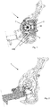
- reference numeral 1 denotes a variable-volume positive displacement pump which interacts with a fluid (a liquid), for example lubricating oil.
- the rotor 2 can rotate about a rotation axis 20.
- the rotor 2 comprises a plurality of slots 33 each housing one of said blades 32. Typically the slots 33 extend radially.
- the pump 1 further comprises a stator 3.
- the stator 3 comprises a collar 30 internally of which the rotor 2 can rotate.
- the collar 30 is also known in the technical sector as the external ring.
- the collar 30 surrounds the rotor 2, in particular surrounds the rotation axis 20.
- the stator 3 defines a housing chamber 34 of the rotor 2.
- the chamber 34 is advantageously cylindrical.
- the pump 1 comprises a first and a second plane 311, 312 (see for example figure 11 ) which are transversal to the rotation axis 20 and which occlude the chamber 34, together with the collar 30.
- the rotor 2 and the stator 3 are eccentric.
- the stator 3 and a rotation axis 20 of the rotor 2 are mobile with respect to one another so as to vary the volume of the pump 1.
- the position of an axis of cylindrical symmetry of the chamber 34 can be varied relative to the position of the rotation axis 20 of the rotor 2.
- the rotation axis 20 preferably remains fixed and the position of the stator 3 is modified.
- the stator 3 can advantageously rotate about a hinged zone or can translate.
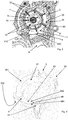
- the stator 3 (collar 30) defines at least a first channel 4 which contributes to an introduction of fluid between the rotor 2 and the stator 3.
- the first channel 4 is a dip or a groove.
- the first channel 4 in a zone in which it is fashioned, reduces an axial thickness of the collar 30 (the axial thickness of the collar is assessed axially, i.e. parallel to the rotation axis 20).
- the pump 1 appropriately comprises a supply conduit 9 of the fluid which opens into the chamber 34.
- the supply conduit 9 opens into the chamber 34 at least through an aspirating opening 90 afforded in the first plane 311.
- the first channel 4 faces and is located at said aspirating opening 90.
- the supply conduit 9 comprises a deflector 900 which generates a first and a second lane 901, 902 for the fluid current.
- the first and second lane 901, 902 diverge from one another.
- the first and/or the second lane 901, 902 have a reduction of the transversal crossing section.
- This deflector 900 is a narrowing member of the conduit 9, which functions as a distributor of the fluid along the first and the second lane 901, 902, facilitating the entrance of the fluid to the chamber 34.
- the aspirating opening 90 extends between a first and a second end 903, 904 (see for example figure 13 ); the first and the second end 903, 904 determine the phasing of the pump 1.
- the first end 903 faces a circumferential portion of the rotor 2 which is more downstream than the circumferential portion faced by the second end 904 (in this case upstream and downstream are calculated with respect to the rotation direction of the rotor 2).
- the first lane 901 terminates at the first end 903 of the aspirating opening 90; the second lane 902 terminates at the second end 904 of the aspirating opening 90.
- the first lane 901 has a larger passage section with respect to the second lane 902 (see for example figure 13 ).
- the first lane 901 reduces the misalignment of the fluid with the fluid present in the chamber 34.
- the first lane 901 increases a component of the fluid motion which is orientated towards the rotation direction of the rotor 2.
- the component of motion of the fluid perpendicular to a radial direction or in equivalent terms tangential to an internal circumference of the chamber 34 and coaxial to the rotation axis 20) increases.
- the second lane 902 enables not altering the phasing of the pump 1 and directing the smallest possible quantity of fluid into the volume.
- the supply conduit 9 is profiled so as to eliminate or in any case minimise the presence of live edges. This is so as to most effectively guide the fluid, reducing fluid-dynamic losses and therefore the possibility of incurring cavitation phenomena.
- the first channel 4 advantageously directs the fluid so as to reduce a misalignment between a first flow of the fluid which comes from said first channel 4 and a second flow of fluid which intercepts the first flow and transits, drawn by the rotor 2, between the first channel 4 and the rotor 2.
- the second flow is the short-circuited fluid already present in the stator 3.
- the first flow of fluid is denoted by reference letter "a” and the second flow of fluid is denoted by reference letter "b".
- the first channel 4 increases the fluid component orientated in the rotation direction of the rotor 2 (in particular the tangential component perpendicular to the radial direction).
- the first channel 4 comprises a first and a second wall 41, 42 which are reciprocally facing. There is advantageously at least a straight segment which connects the first and the second wall 41, 42 without intercepting the rotor 2.
- the fact that the first and the second wall 41, 42 are facing one another is important as it means that the distance between the first and the second wall 41, 42 is limited; this enables appropriately guiding and directing the fluid (if the distance between the first and the second wall 41, 42 were excessive the first channel 4 would not succeed in effectively channelling the fluid in the desired direction).
- the first channel 4 comprises a base surface 43 for connecting the first and the second wall 41, 42.
- the first and the second wall 41, 42 are connected without live edges to the base surface 43.
- a live edge is present between the base surface 43 and the first wall 41; likewise a live edge is present between the base surface 43 and the second wall 42.
- the collar 30 comprises an annular surface 31 which faces and surrounds the rotor 2.
- the minimum distance between the first and the second wall 41, 42 measured along the annular surface 31 is less than 1/3 of the minimum length of a line which, lying entirely on the annular surface 31, surrounds the rotor 2.
- the minimum distance between the first and the second wall 41, 42 measured along a circumference defined by the annular surface 31 is less than 1/3 of the circumference.
- the blades 32 are advantageously radially interposed between a centring ring 5 and the annular surface 31.
- the centring ring 5 limits the maximum insertion of the blades 32 in the slots 33.
- the centring ring 5 advantageously remains coaxial to the annular surface 31 as it is in contact with the radially more internal part of the blades 32.
- the second wall 42 can be connected to the annular surface 31.
- the second wall 42 and the annular surface 31 are advantageously tangential at a common join zone 91 (indicated for example in figure 3 ).
- the annular surface 31 extends along a circle.
- the first channel 4 defines an outlet mouth 44 of the fluid in a zone interposed between the rotor 2 and the stator 3.
- the mouth 44 is preferably subtended by two planes 93, 94 which between them form an angle of less than 100 ° (see for example figures 5 and 9 ).
- the intersection between the two planes 93, 94 lies along a straight line that:
- outlet mouth 44 involves a limited portion of a circumferential extension of the collar 30 enables directing the operating fluid into a predetermined zone.
- the first channel 4 When displacing from a radially more external position 991 towards a radially more internal position 992, the first channel 4 advantageously comprises a ramp 99.
- the ramp 99 reduces the depth of the first channel 4 (the depth is measured parallel to the rotation axis 20).
- the depth of the first channel 4, measured parallel to the rotation axis 20 is on average smaller at the outlet mouth 44 than at the radially more external opening 450.
- the depth of the first channel 4 (measured parallel to the rotation axis 20 of the rotor 2) is nil or in any case tends to 0 at the annular surface 31.
- the extension of the annular surface 31 able to face the end of the blades 32 is increased, thus increasing the volumetric performance, the fluid-dynamic performance and the pump 1 performance.
- the depth of the first channel 4 is progressively reduced.
- the base surface 43 when displacing from a radially more external position towards a radially more internal position, progressively reduces the depth of the first channel 4. This advantageously occurs over the whole radial extension of the first channel 4.
- line 95 indicates a change of slope.
- the axial thickness of the collar 30 progressively increases as it passes from the first to the second wall 41, 42.
- the axial thickness of the collar 30 at the base surface 43 progressively increases as it passes from the first to the second wall 41, 42. This also enables better guiding of the fluid, directing it as schematically indicated in figure 7 .
- the first channel 4 crosses the collar 30 between a radially more external opening 450 and the radially more internal outlet mouth 44.
- the radially more external opening 450 comprises a guide entry 451 for inlet of the fluid. It is advantageously fashioned along a perimeter edge of the opening 450.
- This guide entry 451 further facilitates the inlet of the fluid.
- the guide entry 451 comprises a convexity.
- the guide entry 451 comprises an arched bevel.
- the collar 30 develops in thickness in a radial direction.
- the thickness of the collar 30 is not constant along the first channel 4. As for example illustrated by way of example in figure 5 , the thickness is smaller in a predetermined section interposed between the first and the second wall 41, 42. The thickness progressively increases as it displaces towards the first and the second wall 41, 42.
- the collar 30 comprises a first and a second face 301, 302 which are at least in part parallel to one another and between which the annular surface 31 facing and surrounding the rotor 2 extends.
- the first and second wall 301, 302 are preferably flat.
- the first channel 4 crosses the collar 30 radially.
- the outlet mouth 44 is defined by an opening afforded on the annular surface 31.
- the depth of the first channel 4 tends to nil at the annular surface 31.
- the first channel 4 starting from the first face 301, projects towards the inside of the collar 30, reducing the axial thickness thereof in that portion (note that as mentioned in the foregoing the axial thickness of the collar, as indicated in the foregoing, should be measured axially i.e. parallel to the rotation axis 20).
- first and the second wall 41, 42 are reciprocally asymmetric.
- a terminal portion, radially more internal, of the first and the second wall 41, 42, are reciprocally convergent.
- first wall 41 between the radially more external opening 450 and the outlet mouth 44, extends along a first straight direction 410.
- the second wall 42 between the radially more external opening 450 and the outlet mouth 44, extends along an arched line.
- the first wall 41 and a terminal portion of the second wall 42 diverge.
- a particular application of the present pump 1 is linked to the lubrication of internal combustion engines of vehicles.
- the collar 30 advantageously comprises a second channel 6 which contributes to an introduction of fluid between the rotor 2 and the stator 3.
- the first and second channel 4, 6 are advantageously reciprocally symmetrical. This symmetry is observed with respect to an intermediate plane perpendicular to the rotation axis 20 of the rotor 2.
- the second channel 6 involves only a part of the collar 30 and, where present, reduces the axial thickness of the collar 30 (as previously explained the axial thickness of the collar 30 should be measured parallel to the direction of the rotation axis 20).
- the second channel 6 directs the fluid so as to reduce a misalignment between the first flow of the fluid and the second flow of fluid, already defined in the foregoing, (i.e. a flow that transits in the stator 3 in front of the first channel 4 and is drawn by the rotor 2).
- the second channel 6 advantageously comprises two lateral walls 96, 97 and a connecting surface 98 of the two lateral walls 96, 97. While radially displacing from a more external position to a more internal position, the base surface 43 of the first channel 4 and the connecting surface 98 of the second channel 6 are reciprocally divergent.
- the collar 30 advantageously externally defines a leading edge which separates the fluid flow and guides it towards the first and second channel 4, 6.
- the collar 30 advantageously externally defines a leading edge which separates the fluid flow and guides it towards the first and second channel 4, 6.
- the optimal condition of maximum volume almost all the fluid aspirated by the pump 1 transits through the first and second channel 4, 6. Moving away from the optimal condition of maximum volume increases the quantity of fluid that might also by-pass the first and second channel 4, 6.
- the stator 3 illustrated in the version of figures 1-7 is advantageously typically made of a metal material.
- the stator of figures 8-10 has a shape such that it might also be made of a plastic material.
- the object of the present invention is therefore a system comprising:
- Tests carried out by the Applicant have evidenced a 4% improvement in fluid-dynamic performance of the pump and a reduction in the noise levels if compared to pumps having conventional design and lacking in the claimed specifications.
- the pump of the present invention can be used for lubricating internal combustion engines, enabling a reduction in emissions and preventing power losses.
- the ever-greater attention to this area of problems (especially, but not only, in the automotive sector) in recent years has led to analysing and optimising all pump components.
Landscapes
- Engineering & Computer Science (AREA)
- Mechanical Engineering (AREA)
- General Engineering & Computer Science (AREA)
- Structures Of Non-Positive Displacement Pumps (AREA)
- Rotary Pumps (AREA)
- Compressor (AREA)
Claims (15)
- Verdrängerpumpe mit veränderlicher Verdrängung, umfassend:- einen Blattrotor (2),- einen Stator (3), der einen Bund (30) umfasst, in dessen Innerem sich der Rotor (2) drehen kann, wobei der Stator (3) und eine Drehachse (20) des Rotors (2) so in Bezug zueinander bewegbar sind, dass das Volumen der Pumpe (1) verändert wird,wobei der Bund (30) wenigstens einen ersten Kanal (4) festlegt, um eine Einleitung von Fluid zwischen dem Rotor (2) und dem Stator (3) zu ermöglichen oder dazu beizutragen, wobei der erste Kanal (4) eine axiale Dicke des Bunds (30) in einem Bereich, in dem er ausgebildet ist, reduziert,
dadurch gekennzeichnet, dass
beim Verdrängen von einer radial eher äußeren Position (991) zu einer radial eher inneren Position (992) der erste Kanal (4) eine Rampe (99) festlegt, die die Tiefe des ersten Kanals (4) reduziert, wobei die Tiefe parallel zu der Drehachse (20) gemessen ist. - Pumpe nach Anspruch 1, dadurch gekennzeichnet, dass der erste Kanal (4) den Bund (30) zwischen einer radial eher äußeren Öffnung (450) und einer radial eher inneren Auslassöffnung (44) radial quert.
- Pumpe nach Anspruch 2, dadurch gekennzeichnet, dass die Tiefe des ersten Kanals (4), parallel zu der Drehachse (20) gemessen, im Durchschnitt an der Auslassöffnung (44) kleiner als an der radial eher äußeren Öffnung (450) ist.
- Pumpe nach Anspruch 2 oder 3, dadurch gekennzeichnet, dass die radial eher äußere Öffnung (450) einen Führungseingang (451) zum Einlassen des Fluids umfasst.
- Pumpe nach Anspruch 4, dadurch gekennzeichnet, dass der Führungseingang (451) eine Verbindung umfasst, die eine Ausbuchtung festlegt, die entlang einem Umfangsrand der radial eher äußeren Öffnung (450) entsteht.
- Pumpe nach einem der vorhergehenden Ansprüche, dadurch gekennzeichnet, dass der erste Kanal (4) eine erste und eine zweite Wand (41, 42) umfasst, die wechselseitig einander zugewandt sind.
- Pumpe nach Anspruch 6, dadurch gekennzeichnet, dass der Bund (30) eine ringförmige Fläche (31) umfasst, die dem Rotor (2) zugewandt ist und diesen umgibt, wobei der Mindestabstand zwischen der ersten und der zweiten Wand (41, 42), entlang der ringförmigen Fläche (31) gemessen, kleiner als 1/3 der Mindestlänge einer Linie ist, die vollständig auf der ringförmigen Fläche (31) liegt und den Rotor (2) umgibt.
- Pumpe nach Anspruch 7, dadurch gekennzeichnet, dass die zweite Wand (42) gebogen und tangential mit der ringförmigen Fläche (31) verbunden ist.
- Pumpe nach Anspruch 7 oder 8, dadurch gekennzeichnet, dass die Tiefe des ersten Kanals (4), parallel zu der Drehachse (20) gemessen, an der ringförmigen Fläche (31) Null ist.
- Pumpe nach einem der Ansprüche 6 bis 9, dadurch gekennzeichnet, dass die erste und die zweite Wand (41, 42) wechselseitig asymmetrisch sind.
- Pumpe nach einem der Ansprüche 6 bis 10, dadurch gekennzeichnet, dass sie eine Grundfläche (43) umfasst, die die erste und die zweite Fläche (41, 42) verbindet, wobei die axiale Dicke des Bunds (30) an der Grundfläche (43) zunehmend größer wird, während sie von der ersten zu der zweiten Wand (41, 42) führt.
- Pumpe nach einem der Ansprüche 5 bis 10, dadurch gekennzeichnet, dass der erste Kanal (4) eine Grundfläche (43) zum Verbinden der ersten und der zweiten Wand (41, 42) umfasst, wobei die Pumpe (1) einen zweiten Kanal (6) umfasst, der wiederum zwei Seitenwände (96, 97) und eine Verbindungsfläche (98) der zwei Seitenwände (96, 97) umfasst, wobei beim Verdrängen von einer eher äußeren Position zu einer eher inneren Position die Grundfläche (43) des ersten Kanals (4) und die Verbindungsfläche (98) des zweiten Kanals (6) wechselseitig voneinander abweichen und ein Leiten des Fluids bewirken.
- Pumpe nach einem der vorhergehenden Ansprüche, dadurch gekennzeichnet, dass der Stator (3) eine Gehäusekammer (34) des Rotors (2) festlegt, wobei der Stator (3) eine erste und eine zweite Ebene (311, 312) umfasst, die quer zu der Drehachse (20) verlaufen und zusammen mit dem Bund (30) die Kammer (34) verschließen, wobei die Pumpe (1) eine Versorgungsleitung (9) für das Fluid umfasst, die in die Kammer (34) mündet, wobei die Versorgungsleitung (9) durch eine in der ersten Ebene (311) vorhandene Ansaugöffnung (90) in die Kammer (34) mündet, wobei der erste Kanal (4) der Ansaugöffnung (90) zugewandt ist und sich bei dieser befindet.
- Pumpe nach Anspruch 13, dadurch gekennzeichnet, dass die Versorgungsleitung (9) ein Ablenkblech (900) umfasst, das auf Seiten desselben eine erste und eine zweite Bahn (901, 902) für den Fluidstrom erzeugt, wobei die erste und die zweite Bahn (901, 902) voneinander abweichen, wobei sich die Ansaugöffnung (90) zwischen einem ersten und einem zweiten Ende (903, 904) erstreckt, wobei das erste Ende (903) einem umlaufenden Abschnitt des Rotors (2) zugewandt ist, der in Bezug auf die Drehrichtung des Rotors (2) weiter stromabwärts als der umlaufende Abschnitt, dem das zweite Ende (904) zugewandt ist, gelegen ist, wobei die erste Bahn (901) an dem ersten Ende (903) der Ansaugöffnung (90) endet, wobei die zweite Bahn (902) an dem zweiten Ende (904) der Ansaugöffnung (90) endet, wobei die erste Bahn (901) einen größeren Durchgangsabschnitt in Bezug auf die zweite Bahn (902) aufweist, wobei die erste Bahn (901) einen Bestandteil der die Leitung (9) durchquerenden Fluidbewegung vergrößert, der zu der Drehrichtung des Rotors (2) ausgerichtet ist.
- Pumpe nach einem der vorhergehenden Ansprüche, dadurch gekennzeichnet, dass der erste Kanal (4) das Fluid zum Vergrößern des in die Drehrichtung des Rotors (2) ausgerichteten Fluidbestandteils leitet, um eine Fehlausrichtung zwischen dem ersten Strom des Fluids, der von dem ersten Kanal (4) kommt, und einem zweiten Strom von Fluid, der den ersten Strom unterbricht, vor dem ersten Kanal (4) durchquert und von dem Rotor (2) angezogen wird, zu verringern.
Applications Claiming Priority (1)
| Application Number | Priority Date | Filing Date | Title |
|---|---|---|---|
| IT102016000082659A IT201600082659A1 (it) | 2016-08-04 | 2016-08-04 | Pompa volumetrica a palette |
Publications (2)
| Publication Number | Publication Date |
|---|---|
| EP3279477A1 EP3279477A1 (de) | 2018-02-07 |
| EP3279477B1 true EP3279477B1 (de) | 2019-04-10 |
Family
ID=57610307
Family Applications (1)
| Application Number | Title | Priority Date | Filing Date |
|---|---|---|---|
| EP17184197.6A Active EP3279477B1 (de) | 2016-08-04 | 2017-08-01 | Verdrängerpumpe mit laufschaufelrotor |
Country Status (3)
| Country | Link |
|---|---|
| EP (1) | EP3279477B1 (de) |
| ES (1) | ES2735208T3 (de) |
| IT (1) | IT201600082659A1 (de) |
Families Citing this family (2)
| Publication number | Priority date | Publication date | Assignee | Title |
|---|---|---|---|---|
| DE102020119893A1 (de) | 2020-07-28 | 2022-02-03 | Schwäbische Hüttenwerke Automotive GmbH | Rotationspumpe mit verstellbarem Fördervolumen |
| DE102021125709A1 (de) | 2021-10-04 | 2023-04-06 | Schwäbische Hüttenwerke Automotive GmbH | Rotationspumpe mit einer Verstelleinrichtung |
Family Cites Families (6)
| Publication number | Priority date | Publication date | Assignee | Title |
|---|---|---|---|---|
| US2466622A (en) * | 1942-11-07 | 1949-04-05 | Hpm Dev Corp | Hydraulic axial vane pump or motor |
| DE4200305C2 (de) * | 1992-01-09 | 1995-06-08 | Glyco Metall Werke | Regelbare Flügelzellenpumpe in kompakter Bauweise |
| JP3112544B2 (ja) * | 1992-03-06 | 2000-11-27 | ジヤトコ・トランステクノロジー株式会社 | 可変容量型ベーンポンプ |
| EP2351934A1 (de) * | 2010-01-11 | 2011-08-03 | Pierburg Pump Technology GmbH | Schmiermittelverstellpumpe |
| JP5364606B2 (ja) * | 2010-01-29 | 2013-12-11 | 日立オートモティブシステムズ株式会社 | ベーンポンプ |
| KR101500372B1 (ko) * | 2013-10-14 | 2015-03-18 | 현대자동차 주식회사 | 가변용량 오일펌프를 구비한 밸런스샤프트 모듈 |
-
2016
- 2016-08-04 IT IT102016000082659A patent/IT201600082659A1/it unknown
-
2017
- 2017-08-01 EP EP17184197.6A patent/EP3279477B1/de active Active
- 2017-08-01 ES ES17184197T patent/ES2735208T3/es active Active
Non-Patent Citations (1)
| Title |
|---|
| None * |
Also Published As
| Publication number | Publication date |
|---|---|
| EP3279477A1 (de) | 2018-02-07 |
| ES2735208T3 (es) | 2019-12-17 |
| IT201600082659A1 (it) | 2018-02-04 |
Similar Documents
| Publication | Publication Date | Title |
|---|---|---|
| RU2628135C2 (ru) | Газотурбинный двигатель | |
| US9297276B2 (en) | Side channel blower, in particular a secondary air blower for an internal combustion machine | |
| CN105874212A (zh) | 中间吸入型隔板以及离心式旋转机械 | |
| EP2474743A2 (de) | Fassartige Mehrstufenpumpe | |
| JP6653326B2 (ja) | 排気タービン式過給機のためのコンプレッサ | |
| EP2447538A2 (de) | System und Verfahren zur Montage eines Überschallverdichtersystems mit Überschallverdichterrotor und Verdichteranordnung | |
| EA031306B1 (ru) | Крыльчатка шламового насоса | |
| EP3279477A1 (de) | Verdrängerpumpe mit laufschaufelrotor | |
| EP3156655B1 (de) | Pumpe zum fördern einer hochviskosen flüssigkeit | |
| EP1532367B1 (de) | Radialrad und pumpvorrichtung | |
| EP3156654B1 (de) | Kreiselpumpe zum fördern einer hochviskosen flüssigkeit | |
| CN107820544B (zh) | 自抽吸的泵组件 | |
| RU2205984C2 (ru) | Лопастный насос с боковым каналом и крышка | |
| RU2677299C1 (ru) | Направляющий аппарат центробежного многоступенчатого насоса | |
| CN110388291B (zh) | 用于内燃机的进气段的进气管的管区段 | |
| EP2495445A2 (de) | System und Verfahren zur Anordnung eines Überschallverdichterrotors mit radialem Strömungskanal | |
| RU2448278C2 (ru) | Лопасть рабочего колеса центробежного насоса | |
| JP2017096196A (ja) | 静止ベーンおよび当該静止ベーンを備えた遠心圧縮機 | |
| RU2676168C1 (ru) | Направляющий аппарат центробежного многоступенчатого насоса | |
| JP2008542612A (ja) | 圧送ユニット | |
| JP2018132021A (ja) | 遠心圧縮機及び遠心圧縮機の使用方法 | |
| RU2677306C1 (ru) | Направляющий аппарат центробежного многоступенчатого насоса | |
| RU105695U1 (ru) | Направляющий аппарат центробежного насоса | |
| RU68059U1 (ru) | Переводник муфты перекрестного потока центробежного газосепаратора погружного скважинного насосного агрегата для добычи нефти (варианты) | |
| RU156941U1 (ru) | Рабочее колесо промежуточной ступени центробежного насоса |
Legal Events
| Date | Code | Title | Description |
|---|---|---|---|
| PUAI | Public reference made under article 153(3) epc to a published international application that has entered the european phase |
Free format text: ORIGINAL CODE: 0009012 |
|
| STAA | Information on the status of an ep patent application or granted ep patent |
Free format text: STATUS: THE APPLICATION HAS BEEN PUBLISHED |
|
| AK | Designated contracting states |
Kind code of ref document: A1 Designated state(s): AL AT BE BG CH CY CZ DE DK EE ES FI FR GB GR HR HU IE IS IT LI LT LU LV MC MK MT NL NO PL PT RO RS SE SI SK SM TR |
|
| AX | Request for extension of the european patent |
Extension state: BA ME |
|
| STAA | Information on the status of an ep patent application or granted ep patent |
Free format text: STATUS: REQUEST FOR EXAMINATION WAS MADE |
|
| 17P | Request for examination filed |
Effective date: 20180807 |
|
| RBV | Designated contracting states (corrected) |
Designated state(s): AL AT BE BG CH CY CZ DE DK EE ES FI FR GB GR HR HU IE IS IT LI LT LU LV MC MK MT NL NO PL PT RO RS SE SI SK SM TR |
|
| RIC1 | Information provided on ipc code assigned before grant |
Ipc: F04C 2/344 20060101AFI20180928BHEP Ipc: F04C 14/22 20060101ALI20180928BHEP |
|
| GRAP | Despatch of communication of intention to grant a patent |
Free format text: ORIGINAL CODE: EPIDOSNIGR1 |
|
| STAA | Information on the status of an ep patent application or granted ep patent |
Free format text: STATUS: GRANT OF PATENT IS INTENDED |
|
| INTG | Intention to grant announced |
Effective date: 20181115 |
|
| GRAS | Grant fee paid |
Free format text: ORIGINAL CODE: EPIDOSNIGR3 |
|
| GRAA | (expected) grant |
Free format text: ORIGINAL CODE: 0009210 |
|
| STAA | Information on the status of an ep patent application or granted ep patent |
Free format text: STATUS: THE PATENT HAS BEEN GRANTED |
|
| AK | Designated contracting states |
Kind code of ref document: B1 Designated state(s): AL AT BE BG CH CY CZ DE DK EE ES FI FR GB GR HR HU IE IS IT LI LT LU LV MC MK MT NL NO PL PT RO RS SE SI SK SM TR |
|
| REG | Reference to a national code |
Ref country code: GB Ref legal event code: FG4D |
|
| REG | Reference to a national code |
Ref country code: CH Ref legal event code: EP Ref country code: AT Ref legal event code: REF Ref document number: 1119030 Country of ref document: AT Kind code of ref document: T Effective date: 20190415 |
|
| REG | Reference to a national code |
Ref country code: IE Ref legal event code: FG4D |
|
| REG | Reference to a national code |
Ref country code: DE Ref legal event code: R096 Ref document number: 602017003185 Country of ref document: DE |
|
| REG | Reference to a national code |
Ref country code: NL Ref legal event code: MP Effective date: 20190410 |
|
| REG | Reference to a national code |
Ref country code: LT Ref legal event code: MG4D |
|
| REG | Reference to a national code |
Ref country code: AT Ref legal event code: MK05 Ref document number: 1119030 Country of ref document: AT Kind code of ref document: T Effective date: 20190410 |
|
| PG25 | Lapsed in a contracting state [announced via postgrant information from national office to epo] |
Ref country code: NL Free format text: LAPSE BECAUSE OF FAILURE TO SUBMIT A TRANSLATION OF THE DESCRIPTION OR TO PAY THE FEE WITHIN THE PRESCRIBED TIME-LIMIT Effective date: 20190410 |
|
| PG25 | Lapsed in a contracting state [announced via postgrant information from national office to epo] |
Ref country code: SE Free format text: LAPSE BECAUSE OF FAILURE TO SUBMIT A TRANSLATION OF THE DESCRIPTION OR TO PAY THE FEE WITHIN THE PRESCRIBED TIME-LIMIT Effective date: 20190410 Ref country code: HR Free format text: LAPSE BECAUSE OF FAILURE TO SUBMIT A TRANSLATION OF THE DESCRIPTION OR TO PAY THE FEE WITHIN THE PRESCRIBED TIME-LIMIT Effective date: 20190410 Ref country code: LT Free format text: LAPSE BECAUSE OF FAILURE TO SUBMIT A TRANSLATION OF THE DESCRIPTION OR TO PAY THE FEE WITHIN THE PRESCRIBED TIME-LIMIT Effective date: 20190410 Ref country code: AL Free format text: LAPSE BECAUSE OF FAILURE TO SUBMIT A TRANSLATION OF THE DESCRIPTION OR TO PAY THE FEE WITHIN THE PRESCRIBED TIME-LIMIT Effective date: 20190410 Ref country code: PT Free format text: LAPSE BECAUSE OF FAILURE TO SUBMIT A TRANSLATION OF THE DESCRIPTION OR TO PAY THE FEE WITHIN THE PRESCRIBED TIME-LIMIT Effective date: 20190910 Ref country code: NO Free format text: LAPSE BECAUSE OF FAILURE TO SUBMIT A TRANSLATION OF THE DESCRIPTION OR TO PAY THE FEE WITHIN THE PRESCRIBED TIME-LIMIT Effective date: 20190710 Ref country code: FI Free format text: LAPSE BECAUSE OF FAILURE TO SUBMIT A TRANSLATION OF THE DESCRIPTION OR TO PAY THE FEE WITHIN THE PRESCRIBED TIME-LIMIT Effective date: 20190410 |
|
| PG25 | Lapsed in a contracting state [announced via postgrant information from national office to epo] |
Ref country code: BG Free format text: LAPSE BECAUSE OF FAILURE TO SUBMIT A TRANSLATION OF THE DESCRIPTION OR TO PAY THE FEE WITHIN THE PRESCRIBED TIME-LIMIT Effective date: 20190710 Ref country code: PL Free format text: LAPSE BECAUSE OF FAILURE TO SUBMIT A TRANSLATION OF THE DESCRIPTION OR TO PAY THE FEE WITHIN THE PRESCRIBED TIME-LIMIT Effective date: 20190410 Ref country code: LV Free format text: LAPSE BECAUSE OF FAILURE TO SUBMIT A TRANSLATION OF THE DESCRIPTION OR TO PAY THE FEE WITHIN THE PRESCRIBED TIME-LIMIT Effective date: 20190410 Ref country code: GR Free format text: LAPSE BECAUSE OF FAILURE TO SUBMIT A TRANSLATION OF THE DESCRIPTION OR TO PAY THE FEE WITHIN THE PRESCRIBED TIME-LIMIT Effective date: 20190711 Ref country code: RS Free format text: LAPSE BECAUSE OF FAILURE TO SUBMIT A TRANSLATION OF THE DESCRIPTION OR TO PAY THE FEE WITHIN THE PRESCRIBED TIME-LIMIT Effective date: 20190410 |
|
| REG | Reference to a national code |
Ref country code: ES Ref legal event code: FG2A Ref document number: 2735208 Country of ref document: ES Kind code of ref document: T3 Effective date: 20191217 |
|
| PG25 | Lapsed in a contracting state [announced via postgrant information from national office to epo] |
Ref country code: AT Free format text: LAPSE BECAUSE OF FAILURE TO SUBMIT A TRANSLATION OF THE DESCRIPTION OR TO PAY THE FEE WITHIN THE PRESCRIBED TIME-LIMIT Effective date: 20190410 Ref country code: IS Free format text: LAPSE BECAUSE OF FAILURE TO SUBMIT A TRANSLATION OF THE DESCRIPTION OR TO PAY THE FEE WITHIN THE PRESCRIBED TIME-LIMIT Effective date: 20190810 |
|
| REG | Reference to a national code |
Ref country code: DE Ref legal event code: R097 Ref document number: 602017003185 Country of ref document: DE |
|
| PG25 | Lapsed in a contracting state [announced via postgrant information from national office to epo] |
Ref country code: EE Free format text: LAPSE BECAUSE OF FAILURE TO SUBMIT A TRANSLATION OF THE DESCRIPTION OR TO PAY THE FEE WITHIN THE PRESCRIBED TIME-LIMIT Effective date: 20190410 Ref country code: CZ Free format text: LAPSE BECAUSE OF FAILURE TO SUBMIT A TRANSLATION OF THE DESCRIPTION OR TO PAY THE FEE WITHIN THE PRESCRIBED TIME-LIMIT Effective date: 20190410 Ref country code: SK Free format text: LAPSE BECAUSE OF FAILURE TO SUBMIT A TRANSLATION OF THE DESCRIPTION OR TO PAY THE FEE WITHIN THE PRESCRIBED TIME-LIMIT Effective date: 20190410 Ref country code: RO Free format text: LAPSE BECAUSE OF FAILURE TO SUBMIT A TRANSLATION OF THE DESCRIPTION OR TO PAY THE FEE WITHIN THE PRESCRIBED TIME-LIMIT Effective date: 20190410 Ref country code: DK Free format text: LAPSE BECAUSE OF FAILURE TO SUBMIT A TRANSLATION OF THE DESCRIPTION OR TO PAY THE FEE WITHIN THE PRESCRIBED TIME-LIMIT Effective date: 20190410 |
|
| PLBE | No opposition filed within time limit |
Free format text: ORIGINAL CODE: 0009261 |
|
| STAA | Information on the status of an ep patent application or granted ep patent |
Free format text: STATUS: NO OPPOSITION FILED WITHIN TIME LIMIT |
|
| PG25 | Lapsed in a contracting state [announced via postgrant information from national office to epo] |
Ref country code: SM Free format text: LAPSE BECAUSE OF FAILURE TO SUBMIT A TRANSLATION OF THE DESCRIPTION OR TO PAY THE FEE WITHIN THE PRESCRIBED TIME-LIMIT Effective date: 20190410 Ref country code: IT Free format text: LAPSE BECAUSE OF FAILURE TO SUBMIT A TRANSLATION OF THE DESCRIPTION OR TO PAY THE FEE WITHIN THE PRESCRIBED TIME-LIMIT Effective date: 20190410 |
|
| 26N | No opposition filed |
Effective date: 20200113 |
|
| PG25 | Lapsed in a contracting state [announced via postgrant information from national office to epo] |
Ref country code: TR Free format text: LAPSE BECAUSE OF FAILURE TO SUBMIT A TRANSLATION OF THE DESCRIPTION OR TO PAY THE FEE WITHIN THE PRESCRIBED TIME-LIMIT Effective date: 20190410 |
|
| PG25 | Lapsed in a contracting state [announced via postgrant information from national office to epo] |
Ref country code: MC Free format text: LAPSE BECAUSE OF FAILURE TO SUBMIT A TRANSLATION OF THE DESCRIPTION OR TO PAY THE FEE WITHIN THE PRESCRIBED TIME-LIMIT Effective date: 20190410 Ref country code: SI Free format text: LAPSE BECAUSE OF FAILURE TO SUBMIT A TRANSLATION OF THE DESCRIPTION OR TO PAY THE FEE WITHIN THE PRESCRIBED TIME-LIMIT Effective date: 20190410 Ref country code: LU Free format text: LAPSE BECAUSE OF NON-PAYMENT OF DUE FEES Effective date: 20190801 |
|
| REG | Reference to a national code |
Ref country code: BE Ref legal event code: MM Effective date: 20190831 |
|
| PG25 | Lapsed in a contracting state [announced via postgrant information from national office to epo] |
Ref country code: IE Free format text: LAPSE BECAUSE OF NON-PAYMENT OF DUE FEES Effective date: 20190801 |
|
| PG25 | Lapsed in a contracting state [announced via postgrant information from national office to epo] |
Ref country code: BE Free format text: LAPSE BECAUSE OF NON-PAYMENT OF DUE FEES Effective date: 20190831 |
|
| PGFP | Annual fee paid to national office [announced via postgrant information from national office to epo] |
Ref country code: ES Payment date: 20200917 Year of fee payment: 4 |
|
| REG | Reference to a national code |
Ref country code: CH Ref legal event code: PL |
|
| PG25 | Lapsed in a contracting state [announced via postgrant information from national office to epo] |
Ref country code: LI Free format text: LAPSE BECAUSE OF NON-PAYMENT OF DUE FEES Effective date: 20200831 Ref country code: CH Free format text: LAPSE BECAUSE OF NON-PAYMENT OF DUE FEES Effective date: 20200831 |
|
| PG25 | Lapsed in a contracting state [announced via postgrant information from national office to epo] |
Ref country code: CY Free format text: LAPSE BECAUSE OF FAILURE TO SUBMIT A TRANSLATION OF THE DESCRIPTION OR TO PAY THE FEE WITHIN THE PRESCRIBED TIME-LIMIT Effective date: 20190410 |
|
| PG25 | Lapsed in a contracting state [announced via postgrant information from national office to epo] |
Ref country code: HU Free format text: LAPSE BECAUSE OF FAILURE TO SUBMIT A TRANSLATION OF THE DESCRIPTION OR TO PAY THE FEE WITHIN THE PRESCRIBED TIME-LIMIT; INVALID AB INITIO Effective date: 20170801 Ref country code: MT Free format text: LAPSE BECAUSE OF FAILURE TO SUBMIT A TRANSLATION OF THE DESCRIPTION OR TO PAY THE FEE WITHIN THE PRESCRIBED TIME-LIMIT Effective date: 20190410 |
|
| PG25 | Lapsed in a contracting state [announced via postgrant information from national office to epo] |
Ref country code: MK Free format text: LAPSE BECAUSE OF FAILURE TO SUBMIT A TRANSLATION OF THE DESCRIPTION OR TO PAY THE FEE WITHIN THE PRESCRIBED TIME-LIMIT Effective date: 20190410 |
|
| REG | Reference to a national code |
Ref country code: ES Ref legal event code: FD2A Effective date: 20220926 |
|
| PG25 | Lapsed in a contracting state [announced via postgrant information from national office to epo] |
Ref country code: ES Free format text: LAPSE BECAUSE OF NON-PAYMENT OF DUE FEES Effective date: 20210802 |
|
| PGFP | Annual fee paid to national office [announced via postgrant information from national office to epo] |
Ref country code: GB Payment date: 20220824 Year of fee payment: 6 |
|
| REG | Reference to a national code |
Ref country code: DE Ref legal event code: R081 Ref document number: 602017003185 Country of ref document: DE Owner name: VHIT S.P.A., IT Free format text: FORMER OWNER: VHIT S.P.A. SOCIETA UNIPERSONALE, OFFANENGO, IT |
|
| P01 | Opt-out of the competence of the unified patent court (upc) registered |
Effective date: 20230522 |
|
| GBPC | Gb: european patent ceased through non-payment of renewal fee |
Effective date: 20230801 |
|
| PG25 | Lapsed in a contracting state [announced via postgrant information from national office to epo] |
Ref country code: GB Free format text: LAPSE BECAUSE OF NON-PAYMENT OF DUE FEES Effective date: 20230801 |
|
| PG25 | Lapsed in a contracting state [announced via postgrant information from national office to epo] |
Ref country code: GB Free format text: LAPSE BECAUSE OF NON-PAYMENT OF DUE FEES Effective date: 20230801 |
|
| PGFP | Annual fee paid to national office [announced via postgrant information from national office to epo] |
Ref country code: DE Payment date: 20250827 Year of fee payment: 9 |
|
| PGFP | Annual fee paid to national office [announced via postgrant information from national office to epo] |
Ref country code: FR Payment date: 20250825 Year of fee payment: 9 |