EP3279419A1 - Ausstellschere für einen treibstangenbeschlag - Google Patents
Ausstellschere für einen treibstangenbeschlag Download PDFInfo
- Publication number
- EP3279419A1 EP3279419A1 EP17179697.2A EP17179697A EP3279419A1 EP 3279419 A1 EP3279419 A1 EP 3279419A1 EP 17179697 A EP17179697 A EP 17179697A EP 3279419 A1 EP3279419 A1 EP 3279419A1
- Authority
- EP
- European Patent Office
- Prior art keywords
- locking pin
- ausstellschere
- striking plate
- locking
- plate
- Prior art date
- Legal status (The legal status is an assumption and is not a legal conclusion. Google has not performed a legal analysis and makes no representation as to the accuracy of the status listed.)
- Granted
Links
Images
Classifications
-
- E—FIXED CONSTRUCTIONS
- E05—LOCKS; KEYS; WINDOW OR DOOR FITTINGS; SAFES
- E05D—HINGES OR SUSPENSION DEVICES FOR DOORS, WINDOWS OR WINGS
- E05D15/00—Suspension arrangements for wings
- E05D15/48—Suspension arrangements for wings allowing alternative movements
- E05D15/52—Suspension arrangements for wings allowing alternative movements for opening about a vertical as well as a horizontal axis
- E05D15/522—Suspension arrangements for wings allowing alternative movements for opening about a vertical as well as a horizontal axis with disconnecting means for the appropriate pivoting parts
- E05D15/523—Suspension arrangements for wings allowing alternative movements for opening about a vertical as well as a horizontal axis with disconnecting means for the appropriate pivoting parts using movable rods
-
- E—FIXED CONSTRUCTIONS
- E05—LOCKS; KEYS; WINDOW OR DOOR FITTINGS; SAFES
- E05D—HINGES OR SUSPENSION DEVICES FOR DOORS, WINDOWS OR WINGS
- E05D15/00—Suspension arrangements for wings
- E05D15/48—Suspension arrangements for wings allowing alternative movements
- E05D15/52—Suspension arrangements for wings allowing alternative movements for opening about a vertical as well as a horizontal axis
- E05D15/5205—Suspension arrangements for wings allowing alternative movements for opening about a vertical as well as a horizontal axis with horizontally-extending checks
-
- E—FIXED CONSTRUCTIONS
- E05—LOCKS; KEYS; WINDOW OR DOOR FITTINGS; SAFES
- E05Y—INDEXING SCHEME ASSOCIATED WITH SUBCLASSES E05D AND E05F, RELATING TO CONSTRUCTION ELEMENTS, ELECTRIC CONTROL, POWER SUPPLY, POWER SIGNAL OR TRANSMISSION, USER INTERFACES, MOUNTING OR COUPLING, DETAILS, ACCESSORIES, AUXILIARY OPERATIONS NOT OTHERWISE PROVIDED FOR, APPLICATION THEREOF
- E05Y2900/00—Application of doors, windows, wings or fittings thereof
- E05Y2900/10—Application of doors, windows, wings or fittings thereof for buildings or parts thereof
- E05Y2900/13—Type of wing
- E05Y2900/148—Windows
Definitions
- the invention relates to a Ausstellschere for an espagnolette fitting of a window, a French window or the like with a frame-side fitting part with a wing-side fitting part Ausstellarm for limiting a Ausstellweite in a tilted position, arranged on a longitudinally displaceable drive rod locking pin and arranged on the Ausstellarm strike plate for receiving the locking pin in a rotational position and a closed position of the espagnolette fitting, wherein the locking pin is held in the rotational position behind a locking edge of the striking plate and wherein the locking edge is guided displaceably along the Ausstellarms, and the locking pin facing in the tilted position of an opening adjacent to the locking edge.
- Such Ausstellschere is from the EP 2 312 103 A2 known.
- a strike plate is mounted on the Ausstellarm.
- the strike plate has an opening for insertion and removal of the lock pin and a locking edge for engaging behind the lock pin.
- a slider disposed within the striker also has an aperture and a locking edge and is controlled by the movement of the striker.
- the locking edge of the slider is arranged in a position in front of the opening and in another position in front of the locking edge of the striking plate, depending on the switching sequence of the espagnolette fitting.
- the openings of the slide and the striking plate overlap exclusively in the tilted position of the espagnolette, so that the locking pin can be inserted or removed exclusively in this position in the strike plate. This can be on the switching sequence of the espagnolette fitting in addition to the closed position, the rotational position and the tilted position also create a gap ventilation position at three switching positions of a handle.
- the invention is based on the problem, so far as to form a Ausstellschere of the type mentioned that it avoids a limitation of the Ausstellweite in night ventilation position on the extension.
- the Ausstellschere designed in accordance with another advantageous embodiment of the invention structurally particularly simple when the locking pin is held in the closed position of the espagnolette behind the same locking edge as in the rotational position.
- the structural complexity of the drive of the strike plate designed according to another advantageous embodiment of the invention structurally particularly simple when the strike plate has two end positions, the strike plate is disposed in the tilted position in one end position and in the night ventilation position in the other end position and if the striker plate is drivable by the locking pin between the end positions.
- the lock plate has control edges against which the locking pin comes to entrain the strike plate.
- the strike plate is suitable according to another advantageous embodiment of the invention for right- and left-hinged window when the strike plate has a continuous transverse groove with the opening and a projecting from the transverse groove, the locking edge having longitudinal groove.
- the guide of the striker designed according to another advantageous embodiment of the invention is particularly simple when the strike plate engages around the stay arm laterally.
- the strike plate has a slot into which engages a bolt mounted in the stay. If the bolt is mushroom-shaped, the strike plate is also secured against falling out.
- the latching means are structurally particularly simple if the oblong hole has an elastically yielding side and the latching means are arranged on the flexible side and cooperate in the end positions with the bolt.
- the locking means contributes according to an advantageous embodiment of the invention, when the locking means cooperate with a recess of the extension arm.
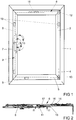
- FIG. 1 shows a window with a frame 1, with a wing 2 and with an espagnolette fitting 3 for locking the wing 2 in the frame 1.
- the wing 2 can be pivoted about a vertical axis 4 relative to the frame 1 in a rotational position D and a horizontal Axis 5 with respect to the frame 1 in a tilted position K tilt.
- the espagnolette fitting 3 can be driven by a handle 7 and has a drive rod 8 for driving a plurality of shutters 9, 10. Some of the closures 10 are arranged in the vertical bars of the window, while other closures 9 are arranged on the lower horizontal rail. Furthermore, in the Ausstellschere 6, a locking pin 11 driven by the drive rod 7.
- the window has a concealed pivot bearing 12 and a corner bearing 13 for supporting the wing 2 on the frame first
- the handle 7 is in the position shown in the position Z, which indicates the closed position in which the wing 2 is located in the frame 1 and is locked on the closures 9, 10.
- the handle 7 can be moved in a rotational position D, in which the wing 2 can be rotated about the vertical axis 4.
- a tilted position K of the handle 7 the wing 2 can tilt about the horizontal axis 5 relative to the frame 1.
- the handle 7 occupy a gap ventilation position L, in which the wing 1 is a gap far from the frame 1 spaced.
- the various positions of the handle 7 are shown in phantom in the drawing.
- the activation of the individual positions of the espagnolette fitting 3 via the switching sequence of the handle 7 marked with arrows.
- the shutters 9, 10 arranged in the vertical stiles and in the lower vertical stile support the wing 2 in front of the frame 1.
- FIG. 2 shows an enlarged view of the Ausstellschere 6 FIG. 1 ,
- the Ausstellschere 6 has a frame-side, attached to the frame 1 fitting part 14 and a wing-side, connected to the wing 2 fitting part 15.
- the fitting parts 14, 15 are connected to each other via a stay 16.
- the fixed on the drive rod 8 locking pin 11 is opposite to a strike plate 17.
- the strike plate 17 is guided longitudinally displaceable on the extension arm 6.
- the Ausstellschere 6 is shown in the gap ventilation position L of the espagnolette fitting 3, in which the wing-side fitting part 15 can be removed from the frame-side fitting part 14 unhindered by locking pin 11 and strike plate 17.
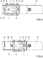
- FIG. 3 shows greatly enlarged a sectional view through a portion of the Ausstellschere 6 FIG. 2 along the line III - III.
- the striking plate 17 has an opening 18 for insertion and removal and a blocking edge 19 for supporting the locking pin 11.
- the strike plate 17 has a continuous transverse groove 20 with the opening 18. Due to the symmetrical design and the continuous design of the transverse groove 20, the strike plate 17 can be used for right and left hand wing. From the transverse groove 20 is at right angles a longitudinal groove 21 from.
- the transverse groove 20 and the longitudinal groove 21 have control edges 22, 23, via which the strike plate 17 can be moved by means of the locking pin 11 along the extension arm 16.
- the handle 7 and thus the espagnolette fitting 3 with the locking pin 11 is in an end position.
- the handle 7 in the rotational position of the locking pin 11 moves into the longitudinal groove 21 behind the locking edge 19.
- the Ausstellschere 6 is blocked and the wing 2 can be rotated about the vertical axis 4.
- This position of the lock pin 11 is in FIG. 3 shown in phantom.
- the positions of the lock pin 11 and the lock plate 17 in the gap ventilation position L and the rotational position D in FIG. 3 characterized.
- the strike plate 17 has latching means 24, with which it cooperates with arranged in the stay 16 recesses 25, 26 and the strike plate 17 in the in FIGS. 3 and 4 holds positions shown.
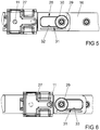
- FIGS. 5 and 6 show the in the FIGS. 3 and 4 illustrated portion of the Ausstellschere 6 with a further embodiment of a strike plate 27.
- the strike plate 27 differs from that of the FIGS. 3 and 4 especially in that it has a slot 28 into which a mounted on the stay 16 bolt 29 penetrates.
- the bolt 29 engages with a mushroom head 30, the strike plate 27 and thus secures it to the stay 16.
- the slot 28 has an elastic side 31 with protruding locking means 32, 33 for latching with the bolt 29.
- the strike plate 27 is like that the FIGS. 3 and 4 constructed and can be from the locking pin 11 between the in the FIGS. 5 and 6 move the displayed end positions.
Landscapes
- Engineering & Computer Science (AREA)
- Mechanical Engineering (AREA)
- Specific Sealing Or Ventilating Devices For Doors And Windows (AREA)
Abstract
Description
- Die Erfindung betrifft eine Ausstellschere für einen Treibstangenbeschlag eines Fensters, einer Fenstertür oder dergleichen mit einem ein rahmenseitiges Beschlagteil mit einem flügelseitigen Beschlagteil verbindenden Ausstellarm zur Begrenzung einer Ausstellweite in einer Kippstellung, mit einem auf einer längsverschieblichen Treibstange angeordneten Schließzapfen und mit einem auf dem Ausstellarm angeordneten Schließblech zur Aufnahme des Schließzapfens in einer Drehstellung und einer Schließstellung des Treibstangenbeschlags, wobei der Schließzapfen in der Drehstellung hinter einer Sperrkante des Schließblechs gehalten ist und wobei die Sperrkante entlang des Ausstellarms verschiebbar geführt ist, und der Schließzapfen in Kippstellung einer Öffnung neben der Sperrkante gegenübersteht.
- Eine solche Ausstellschere ist aus der
EP 2 312 103 A2 bekannt. Bei dieser Ausstellschere ist ein Schließblech auf dem Ausstellarm befestigt. Das Schließblech hat eine Öffnung zum Ein- und Ausführen des Schließzapfens und eine Sperrkante zur Hintergreifung des Schließzapfens. Ein innerhalb des Schließblechs angeordneter Schieber hat ebenfalls eine Öffnung und eine Sperrkante und wird von der Bewegung des Schließzapfens gesteuert. Die Sperrkante des Schiebers ist in Abhängigkeit von der Schaltfolge des Treibstangenbeschlages in einer Stellung vor der Öffnung und in einer anderen Stellung vor der Sperrkante des Schließblechs angeordnet. Die Öffnungen des Schiebers und des Schließblechs überdecken sich ausschließlich in der Kippstellung des Treibstangenbeschlages, so dass der Schließzapfen ausschließlich in dieser Stellung in das Schließblech eingeführt oder entfernt werden kann. Damit lässt sich über die Schaltfolge des Treibstangenbeschlages neben der Schließstellung, der Drehstellung und der Kippstellung auch eine Spaltlüftungsstellung bei drei Schaltstellungen einer Handhabe erzeugen. - In der Spaltlüftungsstellung ist der Schließzapfen bei der bekannten Ausstellschere jedoch in dem Schließblech gehalten. Damit ist die Ausstellweite eines Flügels des Fensters auf die Abmessungen des Schließblechs begrenzt.
- Der Erfindung liegt das Problem zugrunde, eine Ausstellschere der eingangs genannten Art so weiter zu bilden, dass sie eine Begrenzung der Ausstellweite in Spaltlüftungsstellung am Ausstellarm vermeidet.
- Dieses Problem wird erfindungsgemäß dadurch gelöst, dass sämtliche, die Öffnung und die Sperrkante aufweisende Bauteile des Schließblechs verschieblich geführt sind und dass der Schließzapfen in einer Spaltlüftungsstellung der Öffnung im Schließblech gegenübersteht.
- Durch diese Gestaltung sind sämtliche Sperrkanten des Schließblechs verschieblich geführt. Eine Behinderung der Bewegung des Ausstellarms durch unverschiebliche Sperrkanten des Schließblechs wird damit verhindert. Zudem lässt sich der Schließzapfen ausschließlich in der Drehstellung und in der Schließstellung von der einen Sperrkante im Schließblech abstützen. Die Begrenzung der Ausstellweite in der Spaltlüftungsstellung ist von einem anderen Bauteil des Treibstangenbeschlages zu begrenzen und damit der Flügel zu sichern.
- Die Ausstellschere gestaltet sich gemäß einer anderen vorteilhaften Weiterbildung der Erfindung konstruktiv besonders einfach, wenn der Schließzapfen in der Schließstellung des Treibstangenbeschlages hinter der gleichen Sperrkante gehalten ist wie in der Drehstellung.
- Der bauliche Aufwand für den Antrieb des Schließblechs gestaltet sich gemäß einer anderen vorteilhaften Weiterbildung der Erfindung konstruktiv besonders einfach, wenn das Schließblech zwei Endstellungen aufweist, wobei das Schließblech in der Kippstellung in der einen Endstellung und in der Spaltlüftungsstellung in der anderen Endstellung angeordnet ist und wenn das Schließblech von dem Schließzapfen zwischen den Endstellungen antreibbar ist. Vorzugsweise hat das Schließblech Steuerkanten, gegen die der Schließzapfen zur Mitnahme des Schließblechs gelangt.
- Das Schließblech ist gemäß einer anderen vorteilhaften Weiterbildung der Erfindung für rechts- und linksanschlagende Fenster geeignet, wenn das Schließblech eine durchgehende Quernut mit der Öffnung und eine von der Quernut abstehende, die Sperrkante aufweisende Längsnut hat.
- Die Führung des Schließblechs gestaltet sich gemäß einer anderen vorteilhaften Weiterbildung der Erfindung besonders einfach, wenn das Schließblech den Ausstellarm seitlich umgreift.
- Zur weiteren Vereinfachung der Führung des Schließblechs trägt es gemäß einer anderen vorteilhaften Weiterbildung der Erfindung bei, wenn das Schließblech ein Langloch hat, in das ein in dem Ausstellarm befestigter Bolzen eingreift. Wenn der Bolzen pilzkopfförmig gestaltet ist, ist das Schließblech zudem gegen ein Herausfallen gesichert.
- Ein versehentliches Verstellen des Schließblechs lässt sich gemäß einer anderen vorteilhaften Weiterbildung der Erfindung einfach vermeiden, wenn das Schließblech Rastmittel zu seiner Verrastung in den Endstellungen hat.
- Die Rastmittel gestalten sich gemäß einer anderen vorteilhaften Weiterbildung der Erfindung konstruktiv besonders einfach, wenn das Langloch eine elastisch nachgiebige Seite hat und dass die Rastmittel auf der nachgiebigen Seite angeordnet sind und in den Endstellungen mit dem Bolzen zusammenwirken.
- Zur weiteren Vereinfachung des konstruktiven Aufbaus der Rastmittel trägt es gemäß einer vorteilhaften Weiterbildung der Erfindung bei, wenn die Rastmittel mit einer Ausnehmung des Ausstellarms zusammenwirken.
- Die Erfindung lässt zahlreiche Ausführungsformen zu. Zur weiteren Verdeutlichung ihres Grundprinzips sind zwei davon in der Zeichnung dargestellt und werden nachfolgend beschrieben. Diese zeigt in
- Fig. 1
- ein Fenster mit einer erfindungsgemäßen Ausstellschere,
- Fig. 2
- die Ausstellschere aus
Figur 1 in einer vergrößerten Darstellung, - Fig. 3
- stark vergrößert eine Schnittdarstellung durch einen Teilbereich der Ausstellschere mit einer ersten Ausführungsform eines Schließblechs entlang der Linie II - III aus
Figur 2 , - Fig. 4
- das Schließblech aus
Figur 3 in einer Schließstellung, - Fig. 5
- stark vergrößert die Schnittdarstellung aus
Figur 3 mit einer zweiten Ausführungsform eines Schließblechs, - Fig. 6
- das Schließblech aus
Figur 5 in Schließstellung. -
Figur 1 zeigt ein Fenster mit einem Rahmen 1, mit einem Flügel 2 und mit einem Treibstangenbeschlag 3 zur Verriegelung des Flügels 2 in dem Rahmen 1. Der Flügel 2 lässt sich um eine vertikale Achse 4 gegenüber dem Rahmen 1 in eine Drehstellung D verschwenken und um eine horizontale Achse 5 gegenüber dem Rahmen 1 in eine Kippstellung K kippen. Zur Bewegung in die Kippstellung hat der Treibstangenbeschlag 3 eine Ausstellschere 6. Der Treibstangenbeschlag 3 lässt sich über eine Handhabe 7 antreiben und hat eine Treibstange 8 zur Ansteuerung mehrerer Verschlüsse 9, 10. Einige der Verschlüsse 10 sind in den vertikalen Holmen des Fensters angeordnet, während andere Verschlüsse 9 am unteren horizontalen Holm angeordnet sind. Weiterhin ist in der Ausstellschere 6 ein Schließzapfen 11 von der Treibstange 7 antreibbar. Das Fenster hat ein verdeckt angeordnetes Drehlager 12 und ein Ecklager 13 zur Lagerung des Flügels 2 an dem Rahmen 1. - Die Handhabe 7 befindet sich in der dargestellten Stellung in der Position Z, welche die Schließstellung kennzeichnet, in der der Flügel 2 in dem Rahmen 1 liegt und über die Verschlüsse 9, 10 verriegelt ist. Die Handhabe 7 lässt sich in eine Drehstellung D bewegen, in der der Flügel 2 um die vertikale Achse 4 verdreht werden kann. In einer Kippstellung K der Handhabe 7 lässt sich der Flügel 2 um die horizontale Achse 5 gegenüber dem Rahmen 1 kippen. Weiterhin kann die Handhabe 7 eine Spaltlüftungsstellung L einnehmen, in der der Flügel 1 ein Spalt weit von dem Rahmen 1 beabstandet ist. Die verschiedenen Stellungen der Handhabe 7 sind in der Zeichnung strichpunktiert dargestellt. Die Ansteuerung der einzelnen Positionen des Treibstangenbeschlages 3 erfolgt über die mit Pfeilen gekennzeichnete Schaltfolge der Handhabe 7. In der Spaltlüftungsstellung L haltern die in den vertikalen Holmen und die in dem unterem vertikalen Holm angeordneten Verschlüsse 9, 10 den Flügel 2 vor dem Rahmen 1.
-
Figur 2 zeigt eine vergrößerte Darstellung der Ausstellschere 6 ausFigur 1 . Die Ausstellschere 6 hat ein rahmenseitiges, an dem Rahmen 1 befestigtes Beschlagteil 14 und ein flügelseitiges, mit dem Flügel 2 verbundenes Beschlagteil 15. Die Beschlagteile 14, 15 sind über einen Ausstellarm 16 miteinander verbunden. Der auf der Treibstange 8 befestigte Schließzapfen 11 steht einem Schließblech 17 gegenüber. Das Schließblech 17 ist auf dem Ausstellarm 6 längsverschieblich geführt. Die Ausstellschere 6 ist in der Spaltlüftungsstellung L des Treibstangenbeschlages 3 dargestellt, in der das flügelseitige Beschlagteil 15 von dem rahmenseitigen Beschlagteil 14 ungehindert von Schließzapfen 11 und Schließblech 17 entfernt werden kann. -
Figur 3 zeigt stark vergrößert eine Schnittdarstellung durch einen Teilbereich der Ausstellschere 6 ausFigur 2 entlang der Linie III - III. Hierbei ist zu erkennen, dass das Schließblech 17 eine Öffnung 18 zum Ein- und Ausführen und eine Sperrkante 19 zur Abstützung des Schließzapfens 11 hat. Hierzu hat das Schließblech 17 eine durchgehende Quernut 20 mit der Öffnung 18. Durch die symmetrische Gestaltung und die durchgehende Gestaltung der Quernut 20 ist das Schließblech 17 für rechts- und linksanschlagende Flügel einsetzbar. Von der Quernut 20 steht rechtwinklig eine Längsnut 21 ab. Die Quernut 20 und die Längsnut 21 weisen Steuerkanten 22, 23 auf, über die das Schließblech 17 mittels des Schließzapfens 11 entlang des Ausstellarms 16 verschoben werden kann. In der dargestellten Spaltlüftungsstellung befindet sich die Handhabe 7 und damit der Treibstangenbeschlag 3 mit dem Schließzapfen 11 in einer Endstellung. Beim Antrieb der Handhabe 7 in die Drehstellung bewegt sich der Schließzapfen 11 in die Längsnut 21 hinter die Sperrkante 19. Damit ist die Ausstellschere 6 blockiert und der Flügel 2 lässt sich um die vertikale Achse 4 drehen. Diese Stellung des Schließzapfens 11 ist inFigur 3 strichpunktiert dargestellt. Zur Verdeutlichung sind die Positionen des Schließzapfens 11 und des Schließblechs 17 in der Spaltlüftungsstellung L und der Drehstellung D inFigur 3 gekennzeichnet. - Bewegt man ausgehend von der strichpunktiert dargestellten Stellung des Schließzapfens 11 aus
Figur 3 die Handhabe 7 weiter in die Schließstellung Z gelangt der Schließzapfen 11 gegen die eine Steuerkante 22 des Schließblechs 17 und verschiebt dieses in die inFigur 4 dargestellte Stellung. Dies kennzeichnet die Schließstellung Z, in der die Ausstellschere 6 ebenfalls blockiert ist und der Flügel 2 in dem Rahmen 1 verriegelt ist. Ausgehend von der Schließstellung Z kann der Treibstangenbeschlag 3 über die Handhabe 7 in die mit K gekennzeichnete Kippstellung angetrieben werden. In dieser Stellung befindet sich der Schließzapfen 11 außerhalb des Einflussbereichs der Sperrkante 19 in der Quernut 21. Damit kann der Schließzapfen 11 ungehindert aus dem Schließblech 17 entfernt und der Flügel 2 in die Kippstellung K bewegt werden. Die Position des Schließzapfens 11 in Kippstellung ist inFigur 4 strichpunktiert dargestellt. Treibt man den Treibstangenbeschlag 3 ausgehend von der Kippstellung weiter in Richtung Spaltlüftungstellung, gelangt der Schließzapfen 11 gegen die andere Steuerkante 23 und verschiebt das Schließblech 17 in die inFigur 3 dargestellte Stellung. - Das Schließblech 17 hat Rastmittel 24, mit denen es mit in dem Ausstellarm 16 angeordneten Ausnehmungen 25, 26 zusammenwirkt und das Schließblech 17 in den in
Figur 3 und 4 dargestellten Positionen hält. -
Figur 5 und 6 zeigen den in denFiguren 3 und 4 dargestellten Teilbereich der Ausstellschere 6 mit einer weiteren Ausführungsform eines Schließblechs 27. Das Schließblech 27 unterscheidet sich von dem aus denFiguren 3 und 4 vor allem dadurch, dass es ein Langloch 28 hat, in das ein auf dem Ausstellarm 16 befestigter Bolzen 29 eindringt. Der Bolzen 29 übergreift mit einem Pilzkopf 30 das Schließblech 27 und sichert es damit an dem Ausstellarm 16. Weiterhin hat das Langloch 28 eine elastische Seite 31 mit hervorstehenden Rastmitteln 32, 33 zur Verrasterung mit dem Bolzen 29. Ansonsten ist das Schließblech 27 wie das aus denFiguren 3 und 4 aufgebaut und lässt sich von dem Schließzapfen 11 zwischen den in denFiguren 5 und 6 dargestellten Endstellungen verschieben.
Claims (9)
- Ausstellschere (6) für einen Treibstangenbeschlag (3) eines Fensters, einer Fenstertür oder dergleichen mit einem ein rahmenseitiges Beschlagteil (14) mit einem flügelseitigen Beschlagteil (15) verbindenden Ausstellarm (16) zur Begrenzung einer Ausstellweite in einer Kippstellung (K), mit einem auf einer längsverschieblichen Treibstange (8) angeordneten Schließzapfen (11) und mit einem auf dem Ausstellarm (16) angeordneten Schließblech (17, 27) zur Aufnahme des Schließzapfens (11) in einer Drehstellung (D) und einer Schließstellung (Z) des Treibstangenbeschlags (3), wobei der Schließzapfen (11) in der Drehstellung (D) hinter einer Sperrkante (19) des Schließblechs (17, 27) gehalten ist und wobei die Sperrkante (19) entlang des Ausstellarms (16) verschiebbar geführt ist, und der Schließzapfen (11) in Kippstellung (K) einer Öffnung (18) neben der Sperrkante (19) gegenübersteht, dadurch gekennzeichnet, dass sämtliche, die Öffnung (18) und die Sperrkante (19) aufweisende Bauteile des Schließblechs (17, 27) verschieblich geführt sind und dass der Schließzapfen (11) in einer Spaltlüftungsstellung (L) der Öffnung (18) im Schließblech (17, 27) gegenübersteht.
- Ausstellschere nach Anspruch 1, dadurch gekennzeichnet, dass der Schließzapfen (11) in der Schließstellung (Z) des Treibstangenbeschlages (3) hinter der gleichen Sperrkante (19) gehalten ist wie in der Drehstellung (D).
- Ausstellschere nach Anspruch 1 oder 2, dadurch gekennzeichnet, dass das Schließblech (17, 27) zwei Endstellungen aufweist, wobei das Schließblech (17, 27) in der Kippstellung (K) in der einen Endstellung und in der Spaltlüftungsstellung (L) in der anderen Endstellung angeordnet ist und dass das Schließblech (17, 27) von dem Schließzapfen (11) zwischen den Endstellungen antreibbar ist.
- Ausstellschere nach einem der Ansprüche 1 bis 3, dadurch gekennzeichnet, dass das Schließblech (17, 27) eine durchgehende Quernut (20) mit der Öffnung (18) und eine von der Quernut (20) abstehende, die Sperrkante (19) aufweisende Längsnut (21) hat.
- Ausstellschere nach einem der Ansprüche 1 bis 4, dadurch gekennzeichnet, dass das Schließblech (17, 27) den Ausstellarm (16) seitlich umgreift.
- Ausstellschere nach einem der Ansprüche 1 bis 5, dadurch gekennzeichnet, dass das Schließblech (27) ein Langloch (28) hat, in das ein in dem Ausstellarm (16) befestigter Bolzen (29) eingreift.
- Ausstellschere nach einem der Ansprüche 1 bis 6, dadurch gekennzeichnet, dass das Schließblech (17, 27) Rastmittel (24, 32, 33) zu seiner Verrastung in den Endstellungen hat.
- Ausstellschere nach Anspruch 7, dadurch gekennzeichnet, dass das Langloch (28) eine elastisch nachgiebige Seite (31) hat und dass die Rastmittel (32, 33) auf der nachgiebigen Seite (31) angeordnet sind und in den Endstellungen mit dem Bolzen (29) zusammenwirken.
- Ausstellschere nach Anspruch 7, dadurch gekennzeichnet, dass die Rastmittel (24) mit einer Ausnehmung (25, 26) des Ausstellarms (16) zusammenwirken.
Priority Applications (1)
| Application Number | Priority Date | Filing Date | Title |
|---|---|---|---|
| PL17179697T PL3279419T3 (pl) | 2016-08-02 | 2017-07-05 | Wychylny uchwyt nożycowy do okucia zasuwnicy |
Applications Claiming Priority (1)
| Application Number | Priority Date | Filing Date | Title |
|---|---|---|---|
| DE102016214230.5A DE102016214230A1 (de) | 2016-08-02 | 2016-08-02 | Ausstellschere für einen Treibstangenbeschlag |
Publications (2)
| Publication Number | Publication Date |
|---|---|
| EP3279419A1 true EP3279419A1 (de) | 2018-02-07 |
| EP3279419B1 EP3279419B1 (de) | 2019-09-04 |
Family
ID=59298276
Family Applications (1)
| Application Number | Title | Priority Date | Filing Date |
|---|---|---|---|
| EP17179697.2A Active EP3279419B1 (de) | 2016-08-02 | 2017-07-05 | Ausstellschere für einen treibstangenbeschlag |
Country Status (3)
| Country | Link |
|---|---|
| EP (1) | EP3279419B1 (de) |
| DE (1) | DE102016214230A1 (de) |
| PL (1) | PL3279419T3 (de) |
Citations (2)
| Publication number | Priority date | Publication date | Assignee | Title |
|---|---|---|---|---|
| FR1320673A (fr) * | 1962-05-03 | 1963-03-08 | Wilhelm Weidtmann | Fenêtre comportant un battant pouvant, au choix, pivoter autour d'un axe horizontal ou d'un axe vertical |
| EP2312103A2 (de) | 2009-10-15 | 2011-04-20 | Aug. Winkhaus GmbH & Co. KG | Schließvorrichtung mit einem Schließblech zur Aufnahme eines Schließzapfens |
-
2016
- 2016-08-02 DE DE102016214230.5A patent/DE102016214230A1/de not_active Withdrawn
-
2017
- 2017-07-05 PL PL17179697T patent/PL3279419T3/pl unknown
- 2017-07-05 EP EP17179697.2A patent/EP3279419B1/de active Active
Patent Citations (2)
| Publication number | Priority date | Publication date | Assignee | Title |
|---|---|---|---|---|
| FR1320673A (fr) * | 1962-05-03 | 1963-03-08 | Wilhelm Weidtmann | Fenêtre comportant un battant pouvant, au choix, pivoter autour d'un axe horizontal ou d'un axe vertical |
| EP2312103A2 (de) | 2009-10-15 | 2011-04-20 | Aug. Winkhaus GmbH & Co. KG | Schließvorrichtung mit einem Schließblech zur Aufnahme eines Schließzapfens |
Also Published As
| Publication number | Publication date |
|---|---|
| EP3279419B1 (de) | 2019-09-04 |
| DE102016214230A1 (de) | 2018-02-08 |
| PL3279419T3 (pl) | 2020-03-31 |
Similar Documents
| Publication | Publication Date | Title |
|---|---|---|
| DE2547319C3 (de) | Verriegelung für Fenster oder Türen | |
| EP0383003B1 (de) | Feststellvorrichtung für die Flügel von Festern, Türen od. dgl. | |
| DE102008007095B4 (de) | Dreh-Kipp-Beschlag | |
| EP0152791A2 (de) | Stellvorrichtung für Schiebeflügel von Fenstern, Türen od. dgl. | |
| EP3183408B1 (de) | Steuerelement für eine beschlaganordnung | |
| DE102015222116B3 (de) | Ausstellscherenanordnung sowie Schiebetür oder Schiebefenster mit einer solchen Ausstellscherenanordnung | |
| EP3279419B1 (de) | Ausstellschere für einen treibstangenbeschlag | |
| EP2772604B1 (de) | Öffnungsbegrenzer | |
| DE8711496U1 (de) | Verschluß für zweiflügelige Fenster, Türen od. dgl. | |
| DE102005054458B4 (de) | Befestigungseinrichtung für Insektenschutzgitter | |
| EP3371397B1 (de) | Beschlaganordnung | |
| EP1580381B1 (de) | Treibstangenbeschlag | |
| EP2754804A2 (de) | Verschluss für einen Treibstangenbeschlag | |
| DE19906071C2 (de) | Drehbegrenzer für Dreh-Schiebe-Fenster | |
| EP0234213A2 (de) | Treibstangenbeschlag | |
| DE202011103191U1 (de) | Selbstverriegelndes Schloss | |
| DE7520486U (de) | Ausstellvorrichtung für aus Metalloder Kunststoffprofilen zusammengesetzte Fenster und Türen o.dgl | |
| EP1498563B1 (de) | Spaltlüftungsvorrichtung | |
| DE2929382A1 (de) | Kippriegel-verschlussbeschlag fuer kipp-schwenk-fenster, -tueren o.dgl. | |
| DE102014226794A1 (de) | Beschlag zum Einbau zwischen einem Flügel und einem festen Rahmen eines Fensters, einer Tür oder dergleichen sowie Fenster, Tür oder dergleichen mit einem derartigen Beschlag | |
| DE102006035416B4 (de) | Verschluss für einen Treibstangenbeschlag | |
| DE2729394A1 (de) | Verriegelungseinrichtung fuer fenster, tueren o.dgl. | |
| EP1503013A2 (de) | Fenster | |
| EP1580380A2 (de) | Treibstangenbeschlag | |
| DE102004060717A1 (de) | Verschluss zur Verriegelung eines Flügels in einem Rahmen eines Fensters |
Legal Events
| Date | Code | Title | Description |
|---|---|---|---|
| PUAI | Public reference made under article 153(3) epc to a published international application that has entered the european phase |
Free format text: ORIGINAL CODE: 0009012 |
|
| STAA | Information on the status of an ep patent application or granted ep patent |
Free format text: STATUS: THE APPLICATION HAS BEEN PUBLISHED |
|
| AK | Designated contracting states |
Kind code of ref document: A1 Designated state(s): AL AT BE BG CH CY CZ DE DK EE ES FI FR GB GR HR HU IE IS IT LI LT LU LV MC MK MT NL NO PL PT RO RS SE SI SK SM TR |
|
| AX | Request for extension of the european patent |
Extension state: BA ME |
|
| STAA | Information on the status of an ep patent application or granted ep patent |
Free format text: STATUS: REQUEST FOR EXAMINATION WAS MADE |
|
| 17P | Request for examination filed |
Effective date: 20180711 |
|
| RBV | Designated contracting states (corrected) |
Designated state(s): AL AT BE BG CH CY CZ DE DK EE ES FI FR GB GR HR HU IE IS IT LI LT LU LV MC MK MT NL NO PL PT RO RS SE SI SK SM TR |
|
| GRAP | Despatch of communication of intention to grant a patent |
Free format text: ORIGINAL CODE: EPIDOSNIGR1 |
|
| STAA | Information on the status of an ep patent application or granted ep patent |
Free format text: STATUS: GRANT OF PATENT IS INTENDED |
|
| INTG | Intention to grant announced |
Effective date: 20190416 |
|
| GRAS | Grant fee paid |
Free format text: ORIGINAL CODE: EPIDOSNIGR3 |
|
| GRAA | (expected) grant |
Free format text: ORIGINAL CODE: 0009210 |
|
| STAA | Information on the status of an ep patent application or granted ep patent |
Free format text: STATUS: THE PATENT HAS BEEN GRANTED |
|
| AK | Designated contracting states |
Kind code of ref document: B1 Designated state(s): AL AT BE BG CH CY CZ DE DK EE ES FI FR GB GR HR HU IE IS IT LI LT LU LV MC MK MT NL NO PL PT RO RS SE SI SK SM TR |
|
| REG | Reference to a national code |
Ref country code: GB Ref legal event code: FG4D Free format text: NOT ENGLISH |
|
| REG | Reference to a national code |
Ref country code: CH Ref legal event code: EP |
|
| REG | Reference to a national code |
Ref country code: AT Ref legal event code: REF Ref document number: 1175568 Country of ref document: AT Kind code of ref document: T Effective date: 20190915 |
|
| REG | Reference to a national code |
Ref country code: DE Ref legal event code: R096 Ref document number: 502017002188 Country of ref document: DE |
|
| REG | Reference to a national code |
Ref country code: IE Ref legal event code: FG4D Free format text: LANGUAGE OF EP DOCUMENT: GERMAN |
|
| REG | Reference to a national code |
Ref country code: NL Ref legal event code: MP Effective date: 20190904 |
|
| REG | Reference to a national code |
Ref country code: LT Ref legal event code: MG4D |
|
| PG25 | Lapsed in a contracting state [announced via postgrant information from national office to epo] |
Ref country code: HR Free format text: LAPSE BECAUSE OF FAILURE TO SUBMIT A TRANSLATION OF THE DESCRIPTION OR TO PAY THE FEE WITHIN THE PRESCRIBED TIME-LIMIT Effective date: 20190904 Ref country code: LT Free format text: LAPSE BECAUSE OF FAILURE TO SUBMIT A TRANSLATION OF THE DESCRIPTION OR TO PAY THE FEE WITHIN THE PRESCRIBED TIME-LIMIT Effective date: 20190904 Ref country code: SE Free format text: LAPSE BECAUSE OF FAILURE TO SUBMIT A TRANSLATION OF THE DESCRIPTION OR TO PAY THE FEE WITHIN THE PRESCRIBED TIME-LIMIT Effective date: 20190904 Ref country code: BG Free format text: LAPSE BECAUSE OF FAILURE TO SUBMIT A TRANSLATION OF THE DESCRIPTION OR TO PAY THE FEE WITHIN THE PRESCRIBED TIME-LIMIT Effective date: 20191204 Ref country code: FI Free format text: LAPSE BECAUSE OF FAILURE TO SUBMIT A TRANSLATION OF THE DESCRIPTION OR TO PAY THE FEE WITHIN THE PRESCRIBED TIME-LIMIT Effective date: 20190904 Ref country code: NO Free format text: LAPSE BECAUSE OF FAILURE TO SUBMIT A TRANSLATION OF THE DESCRIPTION OR TO PAY THE FEE WITHIN THE PRESCRIBED TIME-LIMIT Effective date: 20191204 |
|
| PG25 | Lapsed in a contracting state [announced via postgrant information from national office to epo] |
Ref country code: RS Free format text: LAPSE BECAUSE OF FAILURE TO SUBMIT A TRANSLATION OF THE DESCRIPTION OR TO PAY THE FEE WITHIN THE PRESCRIBED TIME-LIMIT Effective date: 20190904 Ref country code: ES Free format text: LAPSE BECAUSE OF FAILURE TO SUBMIT A TRANSLATION OF THE DESCRIPTION OR TO PAY THE FEE WITHIN THE PRESCRIBED TIME-LIMIT Effective date: 20190904 Ref country code: GR Free format text: LAPSE BECAUSE OF FAILURE TO SUBMIT A TRANSLATION OF THE DESCRIPTION OR TO PAY THE FEE WITHIN THE PRESCRIBED TIME-LIMIT Effective date: 20191205 Ref country code: LV Free format text: LAPSE BECAUSE OF FAILURE TO SUBMIT A TRANSLATION OF THE DESCRIPTION OR TO PAY THE FEE WITHIN THE PRESCRIBED TIME-LIMIT Effective date: 20190904 Ref country code: AL Free format text: LAPSE BECAUSE OF FAILURE TO SUBMIT A TRANSLATION OF THE DESCRIPTION OR TO PAY THE FEE WITHIN THE PRESCRIBED TIME-LIMIT Effective date: 20190904 |
|
| PG25 | Lapsed in a contracting state [announced via postgrant information from national office to epo] |
Ref country code: NL Free format text: LAPSE BECAUSE OF FAILURE TO SUBMIT A TRANSLATION OF THE DESCRIPTION OR TO PAY THE FEE WITHIN THE PRESCRIBED TIME-LIMIT Effective date: 20190904 Ref country code: EE Free format text: LAPSE BECAUSE OF FAILURE TO SUBMIT A TRANSLATION OF THE DESCRIPTION OR TO PAY THE FEE WITHIN THE PRESCRIBED TIME-LIMIT Effective date: 20190904 Ref country code: RO Free format text: LAPSE BECAUSE OF FAILURE TO SUBMIT A TRANSLATION OF THE DESCRIPTION OR TO PAY THE FEE WITHIN THE PRESCRIBED TIME-LIMIT Effective date: 20190904 Ref country code: IT Free format text: LAPSE BECAUSE OF FAILURE TO SUBMIT A TRANSLATION OF THE DESCRIPTION OR TO PAY THE FEE WITHIN THE PRESCRIBED TIME-LIMIT Effective date: 20190904 Ref country code: PT Free format text: LAPSE BECAUSE OF FAILURE TO SUBMIT A TRANSLATION OF THE DESCRIPTION OR TO PAY THE FEE WITHIN THE PRESCRIBED TIME-LIMIT Effective date: 20200106 |
|
| PG25 | Lapsed in a contracting state [announced via postgrant information from national office to epo] |
Ref country code: SM Free format text: LAPSE BECAUSE OF FAILURE TO SUBMIT A TRANSLATION OF THE DESCRIPTION OR TO PAY THE FEE WITHIN THE PRESCRIBED TIME-LIMIT Effective date: 20190904 Ref country code: SK Free format text: LAPSE BECAUSE OF FAILURE TO SUBMIT A TRANSLATION OF THE DESCRIPTION OR TO PAY THE FEE WITHIN THE PRESCRIBED TIME-LIMIT Effective date: 20190904 Ref country code: IS Free format text: LAPSE BECAUSE OF FAILURE TO SUBMIT A TRANSLATION OF THE DESCRIPTION OR TO PAY THE FEE WITHIN THE PRESCRIBED TIME-LIMIT Effective date: 20200224 Ref country code: CZ Free format text: LAPSE BECAUSE OF FAILURE TO SUBMIT A TRANSLATION OF THE DESCRIPTION OR TO PAY THE FEE WITHIN THE PRESCRIBED TIME-LIMIT Effective date: 20190904 |
|
| REG | Reference to a national code |
Ref country code: DE Ref legal event code: R097 Ref document number: 502017002188 Country of ref document: DE |
|
| PLBE | No opposition filed within time limit |
Free format text: ORIGINAL CODE: 0009261 |
|
| STAA | Information on the status of an ep patent application or granted ep patent |
Free format text: STATUS: NO OPPOSITION FILED WITHIN TIME LIMIT |
|
| PG2D | Information on lapse in contracting state deleted |
Ref country code: IS |
|
| PG25 | Lapsed in a contracting state [announced via postgrant information from national office to epo] |
Ref country code: DK Free format text: LAPSE BECAUSE OF FAILURE TO SUBMIT A TRANSLATION OF THE DESCRIPTION OR TO PAY THE FEE WITHIN THE PRESCRIBED TIME-LIMIT Effective date: 20190904 Ref country code: IS Free format text: LAPSE BECAUSE OF FAILURE TO SUBMIT A TRANSLATION OF THE DESCRIPTION OR TO PAY THE FEE WITHIN THE PRESCRIBED TIME-LIMIT Effective date: 20200105 |
|
| 26N | No opposition filed |
Effective date: 20200605 |
|
| PG25 | Lapsed in a contracting state [announced via postgrant information from national office to epo] |
Ref country code: SI Free format text: LAPSE BECAUSE OF FAILURE TO SUBMIT A TRANSLATION OF THE DESCRIPTION OR TO PAY THE FEE WITHIN THE PRESCRIBED TIME-LIMIT Effective date: 20190904 |
|
| PG25 | Lapsed in a contracting state [announced via postgrant information from national office to epo] |
Ref country code: MC Free format text: LAPSE BECAUSE OF FAILURE TO SUBMIT A TRANSLATION OF THE DESCRIPTION OR TO PAY THE FEE WITHIN THE PRESCRIBED TIME-LIMIT Effective date: 20190904 |
|
| REG | Reference to a national code |
Ref country code: CH Ref legal event code: PL |
|
| REG | Reference to a national code |
Ref country code: BE Ref legal event code: MM Effective date: 20200731 |
|
| PG25 | Lapsed in a contracting state [announced via postgrant information from national office to epo] |
Ref country code: LU Free format text: LAPSE BECAUSE OF NON-PAYMENT OF DUE FEES Effective date: 20200705 Ref country code: LI Free format text: LAPSE BECAUSE OF NON-PAYMENT OF DUE FEES Effective date: 20200731 Ref country code: CH Free format text: LAPSE BECAUSE OF NON-PAYMENT OF DUE FEES Effective date: 20200731 Ref country code: IE Free format text: LAPSE BECAUSE OF NON-PAYMENT OF DUE FEES Effective date: 20200705 Ref country code: FR Free format text: LAPSE BECAUSE OF NON-PAYMENT OF DUE FEES Effective date: 20200731 |
|
| PG25 | Lapsed in a contracting state [announced via postgrant information from national office to epo] |
Ref country code: BE Free format text: LAPSE BECAUSE OF NON-PAYMENT OF DUE FEES Effective date: 20200731 |
|
| GBPC | Gb: european patent ceased through non-payment of renewal fee |
Effective date: 20210705 |
|
| PG25 | Lapsed in a contracting state [announced via postgrant information from national office to epo] |
Ref country code: GB Free format text: LAPSE BECAUSE OF NON-PAYMENT OF DUE FEES Effective date: 20210705 |
|
| PG25 | Lapsed in a contracting state [announced via postgrant information from national office to epo] |
Ref country code: TR Free format text: LAPSE BECAUSE OF FAILURE TO SUBMIT A TRANSLATION OF THE DESCRIPTION OR TO PAY THE FEE WITHIN THE PRESCRIBED TIME-LIMIT Effective date: 20190904 Ref country code: MT Free format text: LAPSE BECAUSE OF FAILURE TO SUBMIT A TRANSLATION OF THE DESCRIPTION OR TO PAY THE FEE WITHIN THE PRESCRIBED TIME-LIMIT Effective date: 20190904 Ref country code: CY Free format text: LAPSE BECAUSE OF FAILURE TO SUBMIT A TRANSLATION OF THE DESCRIPTION OR TO PAY THE FEE WITHIN THE PRESCRIBED TIME-LIMIT Effective date: 20190904 |
|
| PG25 | Lapsed in a contracting state [announced via postgrant information from national office to epo] |
Ref country code: MK Free format text: LAPSE BECAUSE OF FAILURE TO SUBMIT A TRANSLATION OF THE DESCRIPTION OR TO PAY THE FEE WITHIN THE PRESCRIBED TIME-LIMIT Effective date: 20190904 |
|
| P01 | Opt-out of the competence of the unified patent court (upc) registered |
Effective date: 20230516 |
|
| REG | Reference to a national code |
Ref country code: DE Ref legal event code: R081 Ref document number: 502017002188 Country of ref document: DE Owner name: AUG. WINKHAUS SE & CO. KG, DE Free format text: FORMER OWNER: AUG. WINKHAUS GMBH & CO. KG, 48291 TELGTE, DE Ref country code: DE Ref legal event code: R081 Ref document number: 502017002188 Country of ref document: DE Owner name: AUG. WINKHAUS SE, DE Free format text: FORMER OWNER: AUG. WINKHAUS GMBH & CO. KG, 48291 TELGTE, DE |
|
| PGFP | Annual fee paid to national office [announced via postgrant information from national office to epo] |
Ref country code: PL Payment date: 20250624 Year of fee payment: 9 |
|
| REG | Reference to a national code |
Ref country code: DE Ref legal event code: R081 Ref document number: 502017002188 Country of ref document: DE Owner name: AUG. WINKHAUS SE, DE Free format text: FORMER OWNER: AUG. WINKHAUS SE & CO. KG, 48291 TELGTE, DE |
|
| PGFP | Annual fee paid to national office [announced via postgrant information from national office to epo] |
Ref country code: DE Payment date: 20250722 Year of fee payment: 9 |
|
| PGFP | Annual fee paid to national office [announced via postgrant information from national office to epo] |
Ref country code: AT Payment date: 20250721 Year of fee payment: 9 |