EP3277465B1 - Mécanisme de levage pour cloueuse de charpente - Google Patents
Mécanisme de levage pour cloueuse de charpente Download PDFInfo
- Publication number
- EP3277465B1 EP3277465B1 EP16773923.4A EP16773923A EP3277465B1 EP 3277465 B1 EP3277465 B1 EP 3277465B1 EP 16773923 A EP16773923 A EP 16773923A EP 3277465 B1 EP3277465 B1 EP 3277465B1
- Authority
- EP
- European Patent Office
- Prior art keywords
- lifter
- driver member
- driver
- subassembly
- movable arm
- Prior art date
- Legal status (The legal status is an assumption and is not a legal conclusion. Google has not performed a legal analysis and makes no representation as to the accuracy of the status listed.)
- Active
Links
- 230000007246 mechanism Effects 0.000 title claims description 76
- 238000009432 framing Methods 0.000 title description 5
- 230000009471 action Effects 0.000 claims description 12
- 238000004891 communication Methods 0.000 claims description 11
- 230000002159 abnormal effect Effects 0.000 claims description 7
- 238000006073 displacement reaction Methods 0.000 claims description 4
- 238000005516 engineering process Methods 0.000 description 14
- 230000008901 benefit Effects 0.000 description 12
- 230000036316 preload Effects 0.000 description 8
- 238000013461 design Methods 0.000 description 7
- 230000006870 function Effects 0.000 description 5
- 230000002452 interceptive effect Effects 0.000 description 5
- 230000000694 effects Effects 0.000 description 4
- 230000003578 releasing effect Effects 0.000 description 4
- 239000007787 solid Substances 0.000 description 4
- 238000010276 construction Methods 0.000 description 3
- 230000006872 improvement Effects 0.000 description 3
- 230000008878 coupling Effects 0.000 description 2
- 238000010168 coupling process Methods 0.000 description 2
- 238000005859 coupling reaction Methods 0.000 description 2
- 239000006260 foam Substances 0.000 description 2
- 238000012423 maintenance Methods 0.000 description 2
- 239000002023 wood Substances 0.000 description 2
- 230000005355 Hall effect Effects 0.000 description 1
- 238000002485 combustion reaction Methods 0.000 description 1
- 230000006835 compression Effects 0.000 description 1
- 238000007906 compression Methods 0.000 description 1
- 230000005611 electricity Effects 0.000 description 1
- 239000000446 fuel Substances 0.000 description 1
- 238000000034 method Methods 0.000 description 1
- 238000012545 processing Methods 0.000 description 1
- 239000011122 softwood Substances 0.000 description 1
Images


Classifications
-
- B—PERFORMING OPERATIONS; TRANSPORTING
- B25—HAND TOOLS; PORTABLE POWER-DRIVEN TOOLS; MANIPULATORS
- B25C—HAND-HELD NAILING OR STAPLING TOOLS; MANUALLY OPERATED PORTABLE STAPLING TOOLS
- B25C1/00—Hand-held nailing tools; Nail feeding devices
- B25C1/04—Hand-held nailing tools; Nail feeding devices operated by fluid pressure, e.g. by air pressure
- B25C1/047—Mechanical details
-
- B—PERFORMING OPERATIONS; TRANSPORTING
- B25—HAND TOOLS; PORTABLE POWER-DRIVEN TOOLS; MANIPULATORS
- B25C—HAND-HELD NAILING OR STAPLING TOOLS; MANUALLY OPERATED PORTABLE STAPLING TOOLS
- B25C1/00—Hand-held nailing tools; Nail feeding devices
- B25C1/06—Hand-held nailing tools; Nail feeding devices operated by electric power
Definitions
- the technology relates generally to linear fastener driving tools and, more particularly, is directed to portable tools that drive staples, nails, or other linearly driven fasteners.
- At least one embodiment is disclosed as a linear fastener driving tool, in which a cylinder filled with compressed gas is used to quickly force a piston through a driving stroke movement, while also driving a fastener into a workpiece. The piston is then moved back to its starting position during a return stroke by use of a rotary-to-linear lift mechanism, thereby preparing the tool for another driving stroke.
- An elongated driver member is attached to the piston, and has a plurality of spaced-apart protrusions along its longitudinal edges that are used to contact the lift mechanism, which lifts the driver during the return stroke.
- the lift mechanism is pivotable, and is controlled to move into either an interfering position or a non-interfering position with respect to the driver protrusions, and in a "safety mode" also acts as a partial safety device by preventing the driver from making a full driving stroke at an improper time.
- the lift mechanism includes a "pivot arm” that has two ends; the first end is attached to the nailer tool's guide body near the area where the driver member is located, and the first end includes a bearing mounted to a shaft that acts as a pivot point for the entire pivot arm.
- the second end of the pivot arm includes a lifter bearing to which a rotatable lifter gear is attached; the outer region of the rotatable lifter gear has multiple lifter pins that protrude from the gear at right angles, and which are used to engage the protrusions of the driver member.
- the lifter pins of the rotatable lifter gear will force the driver member to undergo a return stroke.
- the second end of the pivot arm is rotated such that the lifter pins are moved away from the driver member, and in that (second) mode of operation, the lifter pins will not interfere with the linear movement of the driver member.
- the driver member is allowed to be forced by the pressurized piston to drive a fastener from the exit end (the bottom) of the nailer tool, which is typically referred to as the driving stroke.
- the driver member has raised areas along its generally planar surface.
- the driver member as noted above, has several spaced-apart protrusions that extend away from its centerline, and in general, the entire driver member is of a uniform thickness, including along its entire longitudinal length and also including the multiple protrusions that are generally at right angles to its longitudinal axis. However, at one or more of the right angle protrusions, there is a small raised area that is designed to make contact with one of the lifter pins of the lift mechanism.
- the open areas between the multiple protrusions of the driver member are the locations where the lifter pins are supposed to move toward and, as the gear at the second end of the pivot arm rotates, the lifter pins should bump against the bottom edge (assuming the tool is pointed downward) of one of the driver member protrusions. That contact forces the driver member upward as the lifter pins continue to rotate through a return stroke.
- the driver member may not be correctly positioned, and the lifter pin might bump against the flat surface of the protrusion of the driver member, instead of bumping against the protrusion's bottom edge (as designed).
- the small raised area of this alternative embodiment suddenly becomes important in that situation; the lifter pin will catch on the lip of that raised area, and will tend to force the driver member to move a small distance.
- the "next" lifter pin (as the gear at the second end of the pivot arm continues to rotate) will then likely find an open area (i.e., between the driver member protrusions) to fit into, and thereby will be able to engage the bottom edge of one of the protrusions and begin a normal lifting cycle to cause a return stroke.
- the lifter pins have cylindrical rollers that can rotate about the arcuate surface of the solid lifter pins. These rollers make the overall structure of the lifter pins somewhat more "slippery,” with respect to making contact with the driver member. This can be important in situations where the driver member is incorrectly positioned at the end of a driving stroke, because if the driver member protrusions end up in a "bad" position, the lifter pins could possibly jam against the driver member. If a jam occurs, then the tool must be deactivated and disassembled so as to un-jam the lifter pins from the driver member.
- the rollers are free to rotate about the outer surface of the otherwise solid lifter pins, and in a situation where the driver member is incorrectly positioned, the rollers will allow the lift mechanism to slip along the surface of the driver member without jamming. At the same time, that action will likely tend to move the driver member upward a small distance, and then the "next" lifter pin will be able to contact the bottom edge of one of the driver member protrusions, forcing the driver upward for a return stroke, and thereby avoiding a jam condition from occurring.
- the lift mechanism is powered by an electric motor that rotates a gear train, which causes a lifter gear at the second end of the pivot arm to rotate.
- a gear train which causes a lifter gear at the second end of the pivot arm to rotate.
- the lifter subassembly will stay in this position until the gear train causes a reverse rotation of a small diameter gear to occur.
- the pivot arm will be pivoted away from the driver member. This action disengages the lifter pins from the protrusions of the driver member, which in turn, clears the driver member from its engagement with the lifter subassembly, thereby freely allowing the pressurized piston to force the driver member downward (assuming the nailer tool is pointing down), and thereby driving a fastener from the bottom of the tool.
- the driving mechanism used in the fastener driving tool disclosed herein includes a pivotable latch that is normally pressed against the driver member.
- a "release solenoid” is controlled by an electronic controller, and when it is time to "drive” a fastener, the release solenoid is energized to move the latch to a second position, where the latch releases from contact with the driver member. This allows the driver member to be quickly pushed by its connecting piston, to drive a fastener that is positioned in the driver track. After the fastener driving stroke is complete, the solenoid de-energizes, and the pivotable latch moves back to its first position where it again contacts the driver member.
- the physical shape and orientation of the latch allows the driver member to move upward (i.e., from its driven position to its ready position), so that it is ready for another driving stroke.
- a fastener driving tool disclosed herein includes an elongated driver member attached to the piston, and has a plurality of spaced-apart protrusions along its longitudinal edges that are used to contact a lift mechanism, which lifts the driver during the return stroke.
- the lift mechanism is pivotable, and is able to float along side the driver member during normal operation; however, the lift mechanism can rotate into a non-interfering position with respect to the driver protrusions, and thereby "release” from making contact with the driver member, when necessary. This release ability allows the lift mechanism to prevent jams in most situations.
- the lift mechanism includes a "pivot arm" that has two ends; the first end is attached to the nailer tool's guide body near the area where the driver member is located, and the first end includes a bearing mounted to a shaft that acts as a pivot point for the entire pivot arm.
- the second end of the pivot arm includes a pair of lifter bearings and a pair of rotatable lifter gears.
- the outer region of the rotatable lifter gear has multiple lifter pins that protrude from each of the lifter gears at right angles, and which are used to engage the protrusions of the driver member. When so engaged (during a first mode of operation), the lifter pins of the rotatable lifter gears will force the driver member to undergo a return stroke.
- the driver member again has raised areas along its generally planar surface.
- the driver member has several spaced-apart protrusions that extend away from its centerline, and in general, the entire driver member is of a uniform thickness, including along its entire longitudinal length and also including the multiple protrusions that are generally at right angles to its longitudinal axis. However, at one or more of the right angle protrusions, there is a small raised area that is designed to make contact with one of the lifter pins of the lift mechanism.
- the open areas between the multiple protrusions of the driver member are the locations where the lifter pins are supposed to move toward and, as the lifter gears at the second end of the pivot arm rotate, the lifter pins should bump against the bottom edge (assuming the tool is pointed downward) of one of the driver member protrusions. That contact forces the driver member upward as the lifter pins continue to rotate through a return stroke.
- the driver member may not be correctly positioned, and the lifter pin might bump against the flat surface of the protrusion of the driver member, instead of bumping against the protrusion's bottom edge (as designed).
- the small raised area of this alternative embodiment suddenly becomes important in that situation; the lifter pin will catch on the lip of that raised area, and will tend to force the driver member to move a small distance.
- the "next" lifter pin (as the gear at the second end of the pivot arm continues to rotate) will then likely find an open area (i.e., between the driver member protrusions) to fit into, and thereby will be able to engage the bottom edge of one of the protrusions and begin a normal lifting cycle to cause a return stroke.
- the lifter pins again have cylindrical rollers that can rotate about the arcuate surface of the solid lifter pins. These rollers make the overall structure of the lifter pins somewhat more slippery, with respect to making contact with the driver member. This can be important in situations where the driver member is incorrectly positioned at the end of a driving stroke, because if the driver member protrusions end up in a "bad" position, the lifter pins could possibly jam against the driver member. If a jam occurs, then the tool must be deactivated and disassembled so as to un-jam the lifter pins from the driver member.
- the rollers are free to rotate about the outer surface of the otherwise solid lifter pins, and in a situation where the driver member is incorrectly positioned, the rollers will allow the lift mechanism to slip along the surface of the driver member without jamming. At the same time, that action will likely tend to move the driver member upward a small distance, and then the "next" lifter pin will be able to contact the bottom edge of one of the driver member protrusions, forcing the driver upward for a return stroke, and thereby avoiding a jam condition from occurring.
- Another air spring fastener driving tool is disclosed in published patent application no. US2006/0180631, by Pedicini , which uses a rack and pinion to move the piston back to its driving position.
- the rack and the pinion gear are decoupled during the drive stroke, and a sensor is used to detect this decoupling.
- the Pedicini tool uses a release valve to replenish the air that is lost between nail drives.
- Senco Brands, Inc. sells a product line of automatic power tools referred to as nailers, including tools that combine the power and the utility of a pneumatic tool with the convenience of a cordless tool.
- nailers One primary feature of such tools is that they use pressurized air to drive a piston that drives the nail.
- pressurized air is re-used, over and over, so there is no need for any compressed air hose, or for a combustion chamber that would require fuel.
- Senco "air tools” are quite reliable and typically can endure thousands of driving cycles without any significant maintenance, they do have wear characteristics for certain components.
- the piston stop (or “bumper”) at the bottom of the drive cylinder can become compressed after thousands of driving cycles, for example.
- the more cycles that a tool is used without any significant maintenance the more compressed the bumper can become, and this compression exhibits a certain mechanical hysteresis which eventually causes the piston to halt at a lower position than it did when the tool was new. Consequently, the driver member (or “driver”) will also stop at a lower position along its longitudinal axis than when the tool was new, and after a time, this can cause variations in operation of the lift mechanism that raises the piston back to its starting position
- a driving mechanism for use in a fastener driving tool is disclosed in US2014/069671 .
- It is another advantage to provide a fastener driving tool that includes a driver member that includes protrusions that are engaged by rotating lifter pins of a lifter subassembly, in which the overall lift mechanism includes a pivot arm that holds the lifter subassembly in an engagement position at times when the driver member is to be lifted, but also allows the lifter subassembly to be pivoted away from the driver member to an open position, at times when the driver member needs to move quickly to drive a fastener.
- a fastener driving tool that includes a latch that engages along the surface of a driver member that is used to drive a fastener, in which the latch will prevent the driving stroke from occurring unless a solenoid is energized to rotate the latch a small distance, thus releasing the latch from its engagement surface against the driver member, and thereby allowing the driver member to drive a fastener.
- a fastener driving tool that includes a driver member having protrusions that are engageable by rotating lifter pins of a lifter subassembly, in which the overall lift mechanism includes a pivot arm that, when located in a first position, holds the lifter subassembly in an engagement position at times when the driver member is to be lifted during normal operating conditions, but also has a degree of freedom such that the pivot arm is movable toward a second position such that, during abnormal operating conditions, the pivot arm is able to automatically release from its first position and allow the lifter subassembly to displace toward the second position, thereby preventing the lifter subassembly and the driver member from jamming.
- a fastener driving tool that includes an elongated driver member having a first contacting surface that are engageable by a second contacting surface of a lifter subassembly, in which the overall lift mechanism includes a movable arm that, when located in a first position, holds the lifter subassembly in an engagement position at times when the driver member is to be lifted during normal operating conditions, but also has a degree of freedom such that the movable arm is movable toward a second position so that, during abnormal operating conditions, the movable arm is able to automatically release from its first position and allow the lifter subassembly to displace toward the second position, thereby preventing the lifter subassembly and the driver member from jamming.
- a driving mechanism for use in a fastener driving tool which comprises: (a) a guide body that receives a fastener that is to be driven from an exit end of the driving mechanism; (b) a movable driver actuation device; (c) an elongated driver member that is in mechanical communication with the movable driver actuation device at a first end of the driver member, the driver member having a second, opposite end that is sized and shaped to push a fastener from the exit end of the driving mechanism, the driver member having a direction of movement between a first end travel location and a second end travel location, the driver member having a first contacting surface between the first end and the second end, the driver member having a ready position proximal to one of the first and second end travel locations; and (d) a lift mechanism which includes a movable arm that exhibits a proximal end and a distal end,
- a driving mechanism for use in a fastener driving tool which comprises: (a) a guide body that receives a fastener that is to be driven from an exit end of the driving mechanism; (b) a movable driver actuation device; (c) an elongated driver member that is in mechanical communication with the movable driver actuation device at a first end of the driver member, the driver member having a second, opposite end that is sized and shaped to push a fastener from the exit end of the driving mechanism, the driver member having a direction of movement between a driven position and a ready position, the driver member having a first contacting surface between the first end and the second end; (d) a lift mechanism which includes a movable arm that exhibits a proximal end and a distal end, the proximal end being in communication with the guide body and the distal end having a lifter subassembly mounted thereto, the lifter subas
- a driving mechanism for use in a fastener driving tool which comprises: (a) a guide body that receives a fastener that is to be driven from an exit end of the driving mechanism; (b) a movable driver actuation device; (c) an elongated driver member that is in mechanical communication with the movable driver actuation device at a first end of the driver member, the driver member having a second, opposite end that is sized and shaped to push a fastener from the exit end of the driving mechanism, the driver member having a direction of movement between a driven position and a ready position, the driver member having at least one longitudinal edge, the driver member having a plurality of spaced-apart protrusions along the at least one longitudinal edge; (d) a lift mechanism which includes a movable arm that exhibits a proximal end and a distal end, the proximal end being movably in communication with the guide body, and the distal
- a driving mechanism for use in a fastener driving tool which comprises: (a) a guide body that receives a fastener that is to be driven from an exit end of the driving mechanism; (b) a movable driver actuation device; (c) an elongated driver member that is in mechanical communication with the movable driver actuation device at a first end of the driver member, the driver member having a second, opposite end that is sized and shaped to push a fastener from the exit end of the driving mechanism, the driver member having a direction of movement between a driven position and a ready position, the driver member having at least one longitudinal edge, the driver member having a plurality of spaced-apart protrusions along the at least one longitudinal edge; (d) a lift mechanism which includes a movable arm that exhibits a proximal end and a distal end, the proximal end being movably in communication with the guide body, and the dis
- first and second preceding an element name, e.g., first inlet, second inlet, etc., are used for identification purposes to distinguish between similar or related elements, results or concepts, and are not intended to necessarily imply order, nor are the terms “first” and “second” intended to preclude the inclusion of additional similar or related elements, results or concepts, unless otherwise indicated.
- Nailer tool 10 includes a pressure chamber 20 that includes a cylinder 30 with a movable driver actuation device, which is a piston 32 in this illustrated embodiment.
- the movable piston 32 is connected to a driver member 90 that, when actuated, drives a fastener from a magazine 42.
- the tool 10 includes a guide body 40, an electric motor 50, a gearbox 52 that receives the output shaft from the electric motor, and several gear train gears 54 that receive the output from the gearbox 52.
- the gear train gears 54 include a first (larger) gear 53, a second (smaller) gear 55, and a third (final) gear 56.
- the second gear is also referred to herein as a "small diameter gear” 55, and the third gear is also referred to herein as a "lifter gear” 56; lifter gear 56 is part of a lifter subassembly 60.
- first gear 53 and second gear 55 are keyed to the same shaft (i.e., pivot shaft 76), so these first and second gears 53 and 55 always rotate together.
- Lifter subassembly 60 includes a lifter shaft 66 that extends from the left side (in the view of FIG. 1 ) to the right side (in this view), and the lifter shaft 66 which is mechanically connected to the lifter gear 56 and to a lifter wheel 64.
- the left side of the lifter subassembly is sometimes referred to as "side A” while the right side in this view is sometimes referred to as "side B," with regard to terminology for the lifter subassembly.
- the lifter gear 56 is, therefore, on side A of the subassembly 60, while the lifter wheel 64 is on side B of that subassembly. Both the lifter wheel and the lifter gear rotate together, via the lifter bearing(s) 58 and lifter shaft 66.
- the electric motor 50 is commanded to rotate by an electronic controller (not shown) when it is desired to lift the combination piston 32 and driver member 90 from their "driven position” to their initial drive or “ready position.”
- an electronic controller not shown
- the lifter gear 56 rotates, via action of the electric motor 50, there are mechanical components that force the driver member 90 upward (in the view of FIG. 1 ), so that the piston is moved further into the pressure chamber 20, which is where the piston will remain at the "ready position,” until it drives the next fastener.
- Both the lifter gear 56 and the lifter wheel 64 have “pins” 62 that protrude from the lifter gear and the lifter shaft at approximately right angles to the circular plane of the wheel 64 or gear 56, respectively.
- These lifter pins 62 are visible on FIG. 1 , and they are illustrated in more detail in some of the other views of these drawings.
- the lifter gear and lifter wheel comprise rotatable disks that each have a plurality of lifter pins extending from a surface of those rotatable disks, and it is the action of these lifter pins 62 that engages the driver member 90 to force it upward, from its driven position to its ready position.
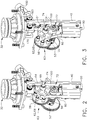
- FIGS. 2 and 3 show the drive assembly without the pressure chamber and cylinder, and without the electric motor and certain other portions of the gear train.
- FIG. 2 illustrates the drive assembly with the lifter subassembly in its "engagement position,” while FIG. 3 shows the same equipment with the lifter subassembly in its "open position.” In FIG. 3 , the opening has been exaggerated for clarity.
- the piston 32 is illustrated at the top of the assembly, showing the piston in its driven position, which means that it is at the bottom of its travel for this tool.
- the lifter pins are illustrated at 62, and there are five of them on each side of the lifter subassembly 60.
- pivot arm 70 which cannot be easily seen on FIGS. 2 and 3 , but can be seen on many other views, especially in the cross-section view of FIG. 7 .
- the pivot arm has a first end at 72, which acts as a pivot axis.
- the second end of the pivot arm is at 74, which is the longitudinal axis for the rotatable lifter shaft 66.
- the second end is the distal end, while the first end is the proximal end, with respect to the guide body 40.
- the lifter subassembly 60 can be swung away from the guide body 40 to become disengaged (as seen in FIG.
- FIGS. 2 and 3 These perspective views of FIGS. 2 and 3 do not readily show the mechanical effects of being engaged or disengaged, but the later views show those effects clearly.
- the pivot arm 70 thus becomes a "movable arm” having displacement that is limited to a maximum travel of between a first position and a second position, inclusive.
- the first position is when the lifter subassembly 60 is engaged (i.e., nested with the guide body 40), and the second position is when the lifter subassembly has been disengaged such that the movable (pivot) arm 70 has displaced (pivoted) its maximum distance away from its engagement (nested) position.
- kicker is a rotatable cam, generally designated by the reference numeral 100, which exhibits a cam profile 104 that can be better seen on FIG. 10 and also FIG. 13 .
- first direction which is the direction required for lifting the driver member 90 from its driven position to its ready position (i.e., for making a return stroke)
- gear train 54 also tends to rotate the rotatable kicker 100 in a clockwise direction as viewed on FIG. 8 .
- FIG. 5 shows an example of how the lifter pins 62 can fit within spaces between the protrusions 92 of the driver member 90.
- the protrusions 92 represent a "first contacting surface”
- the lifter pins 62 represent a "second contacting surface.”
- the driver member 90 must be at its "ready position" before driving a fastener, and the lifter pins 62 are the mechanical devices that previously would have moved the driver member to that ready position. In most circumstances, the lifter pins 62 will remain in contact with the driver member's protrusions 92 before the driving stroke is initiated, even if the motor 50 had previously been turned off for a long time interval. In a typical situation, at the end of the lifting stroke, the driver member 90 will be forced a very short distance downward (as viewed in FIGS. 2-11 ) by air pressure against the top of the piston 32, just as the lifter subassembly 60 stops rotating.
- That small displacement of the driver member will cause the lifter subassembly to rotate slightly in the reverse direction (which would be clockwise as viewed in FIGS. 5 , 7-8 , and 10-11 ), which will cause the lifter wheel 64 to rub against the kicker cam 100, which will slightly rotate the kicker cam 100 counterclockwise (in these same views) until its cam profile 104 comes into play and will lock up further rotation of the lifter wheel 64.
- This "lockup" situation will remain in place to prevent the driver member 90 from moving downward until some other action occurs to disturb the gears of the gear train 54.
- the lifter subassembly 60 When it is time to drive a fastener, the lifter subassembly 60 must literally get out of the way, or the driver member will never be able to move quickly downward to drive the fastener.
- the motor 50 is reversed (rotated in a second direction) for a moment, which causes the second gear 55 to rotate in a counterclockwise direction (as viewed on FIG. 7 ). Since the lifter subassembly 60 typically is locked up at this stage in the operational cycle, the lifter gear 56 cannot rotate; therefore, the entire lifter subassembly 60 will instead be forced to pivot to the left (as viewed in FIG. 7 ), by action of the pivot arm 70 rotating about its pivot axis 72.
- FIGS. 7 and 8 best show this operational mode configuration. (Note: there also are other features that can control the "driving" stroke.)
- the lifter subassembly 60 may not be completely locked up at the beginning of a driving stroke.
- a human user is attempting to drive fasteners as quickly as possible, and perhaps the lifter subassembly 60 has not quite settled down after a return stroke, just as the user pulls the trigger on the nail driving tool to initiate the next driving stroke.
- the motor 50 is reversed for a moment (as per the above description), and the second gear 55 will be rotated (as before) in a counterclockwise direction (as viewed on FIG. 7 ).
- the lifter gear 56 could then slightly rotate in its reverse direction (clockwise on FIG. 7 ), and similarly the lifter wheel 64 will then rotate in the same direction (they are both keyed to the same lifter shaft 66).
- the kicker cam 100 When the lifter wheel rotates in that reversed direction, the kicker cam 100 will rotate counterclockwise (as seen on FIG. 8 ) until its cam profile 104 fully engages against the circumferential outer surface of the lifter wheel 64. As best seen on FIG. 8 , when the kicker wheel 100 rotates a short distance in the counterclockwise direction, its cam profile 104 will be forced against a braking area 106 along the circumferential surface of the lifter wheel 64, which will then lock up the rotation of the lifter wheel 64. When that happens, the pivot arm 70 is forced to rotate in the counterclockwise direction about its pivot axis at its first end 72.
- the output shaft of the electric motor 50 can be stopped and reversed to create the above-discussed reversing action of the lifter subassembly 60.
- an alternative method for reversing the lifter subassembly can be utilized instead of reversing the rotation of the electric motor.
- the gearbox 52 (or some other mechanism) could be provided with parallel shafts, rotating in opposite directions, with a clutch to select which of the parallel shafts will be used to provide mechanical drive to the lifter subassembly 60.
- Other alternative mechanical reversing embodiments are contemplated.
- FIGS. 2 and 3 Another feature readily visible on FIGS. 2 and 3 is a pre-load spring 80.
- the pre-load spring 80 approximates a straight line, which is its normal profile when the lifter subassembly is in its engagement position.
- the pre-load spring 80 is flexible, and as seen in FIG. 3 , it can be bent outward when the lifter subassembly 60 is forced to its open (disengaged) position.
- the pre-load spring 80 exerts a force against the lifter subassembly 60 to ensure that it will stay within its engagement position such that it will not "pop out” from that engagement position during a lifting (return) stroke, unless a jam might otherwise occur.
- the pre-load spring is not necessarily required for this design, because the rotational dynamic forces will tend to keep the lifter subassembly 60 within its engagement position; however the pre-load spring acts as a backup to ensure that function.
- the drive subassembly of the nailer tool is illustrated with the lifter subassembly 60 in its engagement (or engaged) position; this "engagement position” is also sometimes referred to herein as a "first position" of the lifter subassembly 60, and its pivot arm 70.
- the left side in this view is again side A, while the right side of this view is side B.
- the lifter gear 56 is on side A while the lifter wheel 64 is on side B.
- Both of these devices 56 and 64 each have a set of lifter pins 62 that protrude at right angles to the plane of the circular disk profile of either the gear or the wheel.
- the lifter shaft 66 is illustrated in this view.
- the centerline for the first end of the pivot arm is depicted at 72, which acts as the pivot point when seen in a view at a 90 degree angle (such as that of FIG. 5 ).
- FIG. 5 is a section view taken along the line 5-5 of FIG. 4 , and as such, the "side B" portion of the lifter subassembly is not visible. Therefore, the lifter gear 56 can be seen directly, without being blocked by the lifter wheel 64.
- FIG. 5 illustrates the positioning of the lifter pins 62 around the planar surface of the lifter gear 56.
- the lifter pins 62 have rollers 68 that can rotate around the outer surfaces of the lifter pins. These rollers provide a more slippery surface, which can have advantages that will be discussed below.
- the driver member 90 can be seen in FIG. 5 , along with several of its protrusions 92, which in this figure protrude in a direction toward the viewer of this drawing page.
- FIG. 5 also shows one of the lifter pins with roller at 68 fitting between two of the driver member protrusions 92, as would be typical when the lifter subassembly 60 is in its engagement position.
- FIG. 5 also illustrates some of the details of the piston 32 and the piston stop 34.
- the piston stop 34 acts as a bumper, against which the bottom of the piston 32 will strike at the end of a driving stroke.
- the piston 32 is illustrated at its driven position, and as such, will need to be "lifted” upward (in this view) to its ready position before it can act to drive another fastener.
- FIG. 5 Another feature visible in FIG. 5 is a raised area at 94, on one of the driver member protrusions 92.
- the piston stop 34 exhibits significant mechanical hysteresis from wear and tear after many cycles of being struck by the piston 32, then it is possible for the driver member 90 to end up somewhat out of position with respect to where the lifter subassembly would typically engage that driver member.
- the raised area 94 of the protrusion 92 can help to prevent a jam condition of the lifter pins against the driver member. If the driver member 90 ends up at a position such that the lifter pins 62 will miss the bottom edge of one of the protrusions 92, then a lifter pin might solidly impact against the planar surface of the protrusion 92, which potentially could lead to a jam condition. However, the rollers 68 will tend to prevent this jam condition from occurring, since the lifter pins (with the rollers on their surface) of this enhanced embodiment are more slippery, and hence would reduce the chance of a jam occurring in the first place.
- pivot arm 70 itself allows the lifter subassembly 60 to be somewhat moved away (to the left in the view of FIG. 5 ) from the driver member 90 during a lifting (return) stroke.
- the lifter gear 56 happens to begin rotation and a lifter pin 62 strikes one of the driver member protrusions 92 at a point other than along its bottom edge, then the combination of the slight movement of the lifter pin and the fact that the pivot arm 70 can actually rotate about its pivot axis or pivot point 72, allows the entire lifter subassembly 60 to be moved a small distance to the left, thereby tremendously reducing the chance of a jam.
- the features of the improved driver assembly of the technology disclosed herein provide for a more robust system that allows for misalignment between the lifter and the driver "teeth" positions. Moreover, this more robust system is self-correcting with regard to various possible positions of the driver member 90 after it has finished a driving stroke, which often depends on how much wear and tear the piston stop 34 has endured during the lifetime of the nailer tool. The various features that provide for this robustness thus allow for misalignments, and therefore, the improved tool described herein should have an extended lifetime of use without major rebuilds.
- FIGS. 6-8 are all views of the drive assembly in its open or non-engaged position.
- FIG. 7 is a cross-section view taken along the line 7-7 as seen on FIG. 6, and
- FIG. 8 is a side view taken along the line 8-8 as seen on FIG. 6 .
- the lifter subassembly 60 has been rotated a small angular distance in the counterclockwise direction (as seen in these views). Therefore, the lifter pins 62 are out of position from engaging with the driver 90, thereby allowing the driver to be forced downward by the piston 32 and drive a fastener from the exit end of the tool.
- the piston 32 is in its driven position, and it is seated against the top of the piston stop 34.
- the rotation of the pivot arm 70 will occur in this illustrated embodiment because the motor 50 rotation is momentarily reversed, which will cause the rotatable kicker 100 to rotate a small distance in the counterclockwise direction, if it is not already locked up against the lifter wheel 64.
- the cam profile 104 of the kicker 100 will be forced against the circumferential outer surface of the lifter wheel 64, bringing the cam profile 104 hard against the braking area 106 of that lifter wheel surface.
- the lifter wheel will have its rotational movement quickly stopped, and the inertial moment of that rotation is transferred to the pivot arm 70, thereby causing it to rotate in the counterclockwise direction to the position depicted in FIGS. 7 and 8.
- FIG. 8 clearly shows the final position of the cam profile 104 against the braking area surface 106.
- FIG. 8 also illustrates a kicker spring 102 that tends to hold the rotatable kicker 100 in its normal position, which is when the surface of the kicker 100 allows the lifter wheel 64 to slide against their respective surfaces, as the lifter wheel rotates. This occurs while the lifter subassembly 60 is in its engagement position (as seen in FIGS. 4 and 5 ).
- FIGS. 7 and 8 Another feature illustrated in FIGS. 7 and 8 is a pivotable latch 160 that presses against the driver member 90.
- Latch 160 has an engagement extension at 162 that presses directly against one of the surfaces of the driver member 90 and, due to its physical configuration, the latch 160 will allow the driver member to be raised upward (as seen in these views), but will not allow the driver member to be moved downward.
- the latch 160 can act as a safety device in a first mode, and in a second mode, it also acts as a "release device” that allows the driver member to drive a fastener.
- Latch 160 includes an input extension at 164 that is connected to a push rod 152 of a solenoid 150.
- the latch 160 includes a protrusion that acts as a spring mount at 168, to which a latch spring 166 is attached.
- a backup roller 170 that is on the opposite side of the driver member. Backup roller 170 prevents the driver member from deflecting away from the engagement extension 162 of the latch 160. Therefore, when the latch 160 is in its "normal" operating position (as seen in FIG. 7 ), it will be pressed hard against the flat surface of the driver member-on the right hand side as seen in FIG.
- the solenoid 150 is actuated when it is time to drive a fastener.
- the push rod 152 will push against the input extension 164 of the latch, which will then rotate the latch 160 a small amount in the clockwise direction (as seen in FIG. 7 ).
- the engagement extension 162 of the latch will release from the surface of the driver member, thereby allowing the driver to quickly move downward to drive a fastener from the exit end of the tool.
- the lifter subassembly 60 must also be disengaged (moved to its open position), as seen in FIG. 7 , or the driver member 90 will not be able to move quickly downward.
- the lifter subassembly 60 will be in its engagement position, such as that seen in FIGS. 10 and 11 , and the rotation of the lifter gear 56 will tend to push the driver member slightly upward (in these views). This will allow the solenoid 150 to release the latch 160 from the surface of the driver 90, even if the motor had been turned off for a time before beginning this particular driving sequence.
- FIGS. 10 and 11 illustrate the drive assembly of the nailer tool from different angles compared to FIGS. 4 and 5 .
- the lifter subassembly 60 is in its engagement position, which allows the lifter pins to force the driver member 90 upward (in these views) if the lifter subassembly 60 is being rotated.
- the lifter pins 62, the rotatable kicker 100 with its cam profile 104, the pivot arm 70 (in its upright position), and the latch 160 with a solenoid are all depicted.
- FIG. 11 is a cross-section view taken along the lines 11-11, as seen in the top view of FIG. 9 .
- the driver assembly for the nailer tool is depicted in an exploded view that shows most of the component parts as individual items.
- the driver member 90 with its multiple protrusions 92, including protrusions having the raised area 94.
- the various components of the lifter subassembly including the lifter gear 56, the multiple lifter pins 62, the lifter wheel 64, the lifter shaft 66, and the multiple rollers 68 that fit around the lifter pins 62. It should be remembered that the lifter shaft 66 is to be mounted at the second end of the pivot arm, and the pivot arm 70 is visible on FIG. 12 .
- FIG. 12 Also of note on FIG. 12 are the multiple portions of the kicker 100, including a kicker spring 102 and the cam profile 104. Finally, the pre-load spring 80 and the "driving" solenoid 150 are illustrated on FIG. 12 . There are, of course, many fasteners and other parts depicted in this exploded view that have not been described in detail herein.
- the driver assembly can have a variable lift stroke, if desired. This can be accomplished by controlling the number of rotations of the lifter gear 56 during a "lift” (return) stroke.
- a more precise way to control the variable lifting stroke would be to place a sensor proximal to the driver member, and allow the sensor to sense the position of the driver while the driver is being lifted, and then to halt the lifting or return stroke at an appropriate position, which would then become the "ready position" of that driver member for the next driving cycle.
- variable lift stroke can become important. For example, if the type of wood is relatively soft, or if the fastener to be driven is a short nail (relatively speaking), then the amount of power needed to force that nail into the soft wood is reduced compared to larger nails or harder woods. A shorter lifting stroke will save electrical power for the battery pack that provides the electricity for the motor 50, thereby allowing the tool to continue use for a greater number of driving cycles, without changing the battery pack. Of course, if a longer nail or a harder wood is to be the target, then the user would need to inform the nailer tool that more power is needed and the lift stroke should be increased accordingly.
- the lift stroke distance need not be tied directly to a strict number of full rotations of the lifter gear 56; there can be a fractional number of rotations, instead.
- the lifter mechanism was required to stop at a fairly precise rotational position to hold the driver member at a specific place. More to the point, the lifter pins themselves were the actuating devices that held the driver member in place by virtue of the lifter pins directly holding against the bottom edge of the right-angle protrusions of the driver member.
- the latch 160 holds the driver member in place once the lift stroke has been accomplished, and it makes no difference as to exactly how many lifter gear rotations were needed to position of the driver member for that next driving stroke distance.
- the precise position of the driver member when it is moved to its ready position is infinitely variable, and does not depend in the least upon an exact number of lifter rotations (or even an exact fraction of a lifter rotation that correspond to particular positions of the lifter pins 62 at the end of the lift or return stroke). This is another improvement of the new technology disclosed herein.
- FIG. 13 is a perspective view of the rotatable kicker 100.
- the cam profile is clearly visible at 104, and a spring mount extension is visible at 108.
- driver member 90 could be driven toward the exit end by a type of driver actuation device other than a gas spring.
- the piston 32 could have a top circular area that is forced downward (in the view of FIG. 5 ) by a mechanical spring, which could be a fast-acting coil spring, for example, thereby also causing driver member 90 to quickly move downward (in this view).
- a mechanical spring which could be a fast-acting coil spring, for example, thereby also causing driver member 90 to quickly move downward (in this view).
- an alternative driver actuation device could use a different type of mechanical force, for example, applied by compressed foam. In such alternative embodiments, there would be no need for a cylinder at all, and instead the coil spring (or other device) would merely need a mechanical guide to keep it moving in a correct motion.
- Nailer tool 210 includes a pressure chamber 220 that includes a cylinder 230 with a movable driver actuation device, which is a piston 232 in this alternative embodiment.
- the movable piston 232 is connected to a driver member 290 (not seen in this view) that, when actuated, drives a fastener from a magazine (not seen in this view).
- the tool 210 includes a guide body 240, an electric motor with bracket 250, a pinion gear 251 (see FIG.
- the gear train set 254 includes a first bevel gear 253, a second bevel gear 255, and two (smaller) spur gears 256 and 257.
- the two smaller gears 256 and 257 are also referred to herein as "pivot gears," which are part of a pivot arm subassembly 271. Note that the second bevel gear 255 and the two pivot gears, 256 and 257, are all keyed to the same shaft (i.e., a pivot shaft 276), so these gears 255, 256, and 257 always rotate together.
- a lifter subassembly 260 includes a lifter shaft 266 that extends from the left side (in the view of FIG. 1 ) to the right side (in this view); the lifter shaft 266 is mechanically connected to a pair of (larger) lifter gears 263 and 264.
- the left side of the lifter subassembly 260 is sometimes referred to as "side A" while the right side in this view is sometimes referred to as "side B,” with regard to terminology for the lifter subassembly.
- the first pivot gear 256 and first lifter gear 263 are, therefore, on side A of the subassembly 260, while the second pivot gear 257 and second lifter gear 264 are on side B of that subassembly. Both lifter gears 263 and 264 rotate together, via lifter bearing(s) 258 (see FIG. 18 ) and the lifter shaft 266.
- the electric motor 250 is commanded to rotate by an electronic controller (not shown) when it is desired to lift the combination piston 232 and a driver member 290 from their "driven position” to their initial drive or “ready position.”
- an electronic controller not shown
- the lifter gears 263 and 264 rotate, via action of the electric motor 250, there are mechanical components that force the driver member 290 upward (with respect to the view of FIG. 14 ), so that the piston is moved further into the pressure chamber 220, which is where the piston will remain at the "ready position,” until it drives the next fastener.
- Both lifter gear 263 and 264 have “pins” 262 that protrude from the lifter gear and the lifter shaft at approximately right angles to the circular planes of the gear 263 or gear 264, respectively.
- These lifter pins 262 are visible on FIG. 1 , and they are illustrated in more detail in some of the other views of these drawings.
- the lifter gears each comprise rotatable disks that each have a plurality of lifter pins extending from a surface of those rotatable disks, and it is the action of these lifter pins 262 that engages the driver member 290 to force it upward, from its driven position to its ready position.
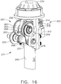
- FIGS. 15 and 16 show the drive assembly without the pressure chamber and cylinder, and without the electric motor and certain other portions of the gear train.
- FIG. 15 illustrates the drive assembly with the lifter subassembly in its "engagement position”
- FIG. 16 shows the same equipment with the lifter subassembly in its "open position.”
- the opening has been exaggerated for clarity.
- the lifter pins are illustrated at 262, and there are three of them on each side of the lifter subassembly 260.
- pivot arm 270 which cannot be easily seen on FIGS. 15 and 16 , but can be seen on many other views, especially in the cross-section view of FIG. 20 .
- the pivot arm has a first end at 272, which acts as a pivot axis.
- the second end of the pivot arm is at 274, which is the longitudinal axis for the rotatable lifter shaft 266.
- the second end is the distal end, while the first end is the proximal end, with respect to the guide body 240.
- the lifter subassembly 260 can be swung away from the guide body 240 to become disengaged (as seen in FIG.
- FIGS. 15 and 16 These perspective views of FIGS. 15 and 16 do not readily show the mechanical effects of being engaged or disengaged, but the later views show those effects clearly.
- the pivot arm 270 thus becomes a "movable arm" having displacement that is limited to a maximum travel of between a first position and a second position, inclusive.
- the first position is when the lifter subassembly 260 is engaged (i.e., nested with the guide body 240), and the second position is when the lifter subassembly has been disengaged such that the movable (pivot) arm 270 has displaced (pivoted) its maximum distance away from its engagement (nested) position.
- the lifter pins 262 tend to engage teeth 292 of the driver member 290, and when the pins 262 actually engage those driver teeth 292, then the driver member 290 is "lifted” from its driven position to its ready position (thereby making a return stroke).
- the driver teeth 292 are often referred to herein as “spaced-apart protrusions.”
- the lifter gears 263 and 264 are rotated in that first direction, which is counterclockwise in the view of FIG.
- FIG. 18 shows an example of how the one of the lifter pins 262 can fit within a space between the protrusions 292 of the driver member 290.
- the protrusions 292 also represent a "first contacting surface”
- the lifter pins 262 also represent a "second contacting surface.”
- the driver member 290 must be at its "ready position" before driving a fastener, and the lifter pins 262 are the mechanical devices that previously would have moved the driver member to that ready position. In most circumstances, the lifter pins 262 will remain in contact with the driver member's protrusions 292 before the driving stroke is initiated, even if the motor 250 had previously been turned off for a long time interval. The lifter pin 262 will remain in contact with one of the driver member's protrusions 292, thereby preventing the driver member 290 from moving downward until the next driving action occurs.
- Latch mechanism 300 that prevents the driver member 290 from moving through a driving stroke under the wrong conditions.
- Latch mechanism 300 includes a solenoid 310 that is controlled by the tool's electronic system controller (not shown), a spring-loaded solenoid plunger (or push rod) 312, a latch push arm 314, a latch shaft 316, and a rotatable latch member 320.
- a coil spring 318 surrounds the plunger 312.
- the latch member 320 is shaped with an extension 322 that is positioned to either "catch” (i.e., engage) the driver member's protrusions 292, or to not catch (i.e., to be disengaged from) those driver member protrusions 292.
- the latch mechanism is engaged, as can be seen by its extension 322 being directly in the path of the driver member protrusions 292, thereby preventing the driver member from "driving.”
- the extension 322 would catch the nearest tooth 292 of the driver member 290, if that driver member started to move unexpectedly downward (in this view), and thus extension 322 would limit the driver member's movement to a very short distance-too short to drive a fastener.
- This safety feature thereby prevents a person being injured in the event that such person might attempt to open the tool (for servicing, for example), or otherwise somehow cause the driver member 290 to slip past the lifter pin 262.
- the latch mechanism 300 has been disengaged (by energizing the solenoid 310), and the latch extension 322 is not in an engagement position, and thus would not catch any of the driver member protrusions 292 if the driver member 290 were to move downward.
- This is the mode of operation that occurs just before a true (i.e., a planned) shot is to occur; the latch has been disengaged, but the lifter pin 262 is still holding one of the driver teeth 292 in place, thereby preventing a downward driving stroke from occurring quite yet.
- the only thing that needs to occur for commencing the driving stroke is to move the lifter pin 262 out of the way.
- both the latch mechanism and the lifter subassembly 260 have been disengaged, and the driver member 290 is, therefore, ready to be pushed downward (in the views of FIGS. 15-24 ) to create a driving stroke of the piston/driver combination.
- the round lifter gear 263 has been rotated counterclockwise (as seen in FIG. 24 ) to the position where the "last" lifter pin 262 has just now cleared out of the way of the prospective downward movement of the driver member 290, by releasing contact between the lifter pin 262 and the driver member's protrusion (or tooth) 292. It will be understood that this view of FIG. 24 only exists for a tiny moment of time, since the pressure against the top of the drive piston 232 will immediately and quickly force downward the driver/piston combination, to drive a fastener in a driving stroke.
- the lifter subassembly 260 When it is time to correctly drive a fastener, the lifter subassembly 260 must literally get out of the way, or the driver member will never be able to move quickly downward to drive the fastener.
- the motor 250 is energized to rotate the gear train 254, which in turn rotates both lifter gears 263 and 264.
- the driver member Once the "final" lifter pin 262 moves to a release position where it clears the prospective path of the driver member 290, the driver member will immediately be allowed to be forced quickly downward by the pressurized air above the piston 232, thereby driving a fastener from the exit end of the tool. (Note: there also are other features that can control the "driving" stroke.)
- FIG. 24 there are three lifter pins 262 per lifter gear 263 (and lifter gear 264, not visible in this view). These three lifter pins 262 are not spaced at equal distances along the outer diameter of the lifter gears. Instead, there is a gap between the "final" lifter pin that is closest to the driver protrusion 292 on FIG. 24 and the "next" lifter pin that would make contact with the driver member 290, if the lifter gear 263 would rotate further in the counterclockwise direction. This gap allows the driver member 290 to "drive” without requiring the lifter subassembly to be pivoted out of the way. In other words, to allow the driver member to undergo a driving stroke, the pivot arm subassembly 271 does not need to "release” or pivot away at all from the guide body 240. This is quite different from the embodiments illustrated in FIGS. 1-13 .
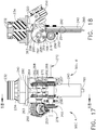
- FIGS. 17 and 18 the drive subassembly of the nailer tool is illustrated with the lifter subassembly 260 in its engaged (or engagement) position; this "engagement position” is also sometimes referred to herein as a "first position" of the lifter subassembly 260, and its pivot arm 270.
- the left side in this view is again side A, while the right side of this view is side B.
- the lifter gear 263 is on side A while the lifter gear 264 is on side B. Both of these gears 263 and 264 each have a set of lifter pins 262 that protrude at right angles to the plane of the circular disk profile of either such gear.
- the lifter shaft 266 is illustrated in this view.
- the centerline for the first end of the pivot arm is depicted at 272, which acts as the pivot point when seen in a view at a 90 degree angle (such as that of FIG. 18 ).
- FIG. 18 is a section view taken along the line 18-18 of FIG. 17 , and as such, the "side B" portion of the lifter subassembly is not visible. Therefore, the lifter gear 263 can be seen directly, without being blocked by the other lifter gear 264.
- FIG. 18 illustrates the positioning of the lifter pins 262 around the planar surface of the lifter gear 263.
- the lifter pins 262 have rollers 268 that can rotate around the outer surfaces of the lifter pins. These rollers provide a more slippery surface, which can have advantages that will be discussed below.
- the driver member 290 can be seen in FIG. 18 , along with several of its protrusions 292, which in this figure protrude in a direction toward the viewer of this drawing page. (See FIG. 25 for a better view of the driver member 290.)
- FIG. 18 also shows one of the lifter pins (with roller at 268) fitting in a space between two of the driver member protrusions 292, as would be typical when the lifter subassembly 260 is in its engagement position. Note that on FIG. 18 , the driver member 290 is illustrated in its "driven” position, after a driving stroke has occurred. Once the driver member moves to this position, it cannot be “fired” again until it has been lifted back to its "ready” position, by way of a return stroke, caused by the lifter subassembly 260.
- FIG. 18 also illustrates some of the details of the piston 232 and the piston stop 234.
- Piston stop 234 acts as a bumper, against which the bottom of the piston 232 will strike at the end of a driving stroke.
- the piston 232 is illustrated at its driven position, and as such, will need to be "lifted” upward (in this view) to its ready position before it can act to drive another fastener. (As will be understood, the piston and driver are mechanically connected in this illustrated embodiment, and as such, always act together.)
- FIG. 18 Another feature visible in FIG. 18 is a raised area at 294, on most of the driver member protrusions 292.
- the piston stop 234 exhibits significant mechanical hysteresis from wear and tear after many cycles of being struck by the piston 232, then it is possible for the driver member 290 to end up somewhat out of position with respect to where the lifter subassembly would typically engage that driver member (at least, as compared to where the driver member 290 used to end up when the entire tool was new).
- the raised area 294 of the protrusions 292 can help to prevent a jam condition of the lifter pins against the driver member. If the driver member 290 ends up at a position such that the lifter pins 262 will miss the bottom edge of one of the protrusions 292, then a lifter pin might solidly impact against the planar surface of the protrusion 292, which potentially could lead to a jam condition. However, the rollers 268 will tend to prevent this jam condition from occurring, since the lifter pins (with the rollers on their surface) of this improved embodiment are more slippery, and hence would reduce the chance of a jam occurring in the first place.
- next lifter pin 262 will tend to fall between those two protrusions and begin a normal lift by catching the bottom edge of the "higher" driver protrusion 292, thereby beginning a return stroke and lifting the driver member 290 back to its ready position.
- pivot arm 270 itself allows the lifter subassembly 260 to be somewhat moved away (to the left in the view of FIG. 18 ) from the driver member 290 during a lifting (return) stroke.
- the pivot arm 270 can actually somewhat rotate about its pivot axis or pivot point 272, allows the entire lifter subassembly 260 to be moved a small distance to the left (as viewed on FIG. 18 ), thereby tremendously reducing the chance of a jam.
- This feature in combination with the rollers 268 and the raised areas 294 of the driver member protrusions 292, will tend to significantly reduce the chances of a jam.
- the features of the improved driver assembly of the technology disclosed herein provide for a more robust system that allows for misalignment between the lifter and the driver "teeth" positions. Moreover, this more robust system is self-correcting with regard to various possible positions of the driver member 290 after it has finished a driving stroke, which often depends on how much wear and tear the piston stop 234 has endured during the lifetime of the nailer tool. The various features that provide for this robustness thus allow for misalignments, and therefore, the improved tool described herein should have an extended lifetime of use without major rebuilds.
- all embodiments of the technology disclosed herein include this more robust feature that allows the lifting mechanism to automatically release from mechanical contact with the driver member, if necessary to prevent a jam, at times when the lifting mechanism is attempting to implement a return stroke by lifting the driver/piston combination from the driven position to the ready position.
- This release condition should not be necessary for "normal operating conditions,” because the lifter pins should readily fit into a space between driver teeth and thereby make initial contact with the bottom edge of one of those driver teeth.
- the driver may have stopped at an improper location along its linear movement, and the driver teeth may thereby be completely out of proper positions as the lifter pins attempt to make contact with those driver teeth.
- This "abnormal operating condition" scenario is precisely what the automatic release function of the lifting mechanism is designed to handle, so that the lifter gears can be automatically pivoted away from the driver member, and almost always prevent a jam or other unstable condition from arising, during an attempted return stroke of the driver/piston combination.
- FIGS. 19-21 are all views of the drive assembly in its open or non-engaged position.
- FIG. 20 is a cross-section view taken along the line 20-20 as seen on FIG. 19, and
- FIG. 21 is a side view taken along the line 21-21 as seen on FIG. 19 .
- the lifter subassembly 260 has been rotated a small angular distance in the counterclockwise direction (as seen in these views). Therefore, the lifter pins 262 are out of position from engaging with the driver 290.
- the piston 232 is in its driven position, and it is seated against the top of the piston stop 234.
- the rotation of the pivot arm 270 will occur in this illustrated alternative if one of the lifter pins 262 is forced "too hard” against the driver member 290.
- the pivot arm subassembly 271 is designed with a mechanical geometry such that the rotational dynamic forces will tend to keep the lifter subassembly 260 engaged within its nested position with respect to the guide body 240.
- the act of "releasing" is what the pivot arm subassembly 271 does when a lifter pin 262 would otherwise jam against the driver member 290 (or one of its teeth 292), or the lifter subassembly 260 is unable to move the driver member 290, and therefore, would try to "slip" along the face of the driver 290, instead of locking and jamming.
- This releasing action occurs when the pivot arm 270 actually pivots (i.e., rotates) about its pivot axis 272.
- pivot arm spring 280 Another feature readily visible on FIGS. 15 and 16 is a pivot arm spring 280.
- the distal (bottom, in this view) portion of pivot arm spring 280 approximates a straight line, which is its normal profile when the lifter subassembly is in its engagement position.
- the pivot arm spring 280 is flexible, and as seen in FIG. 16 , it can be bent outward when the lifter subassembly 260 is forced to its open (disengaged) position.
- the pivot arm spring 280 exerts a force against the lifter subassembly 260 to ensure that it will stay within its engagement position such that it will not “pop out” from that engagement position during a lifting (return) stroke, unless a jam might otherwise occur.
- the driver assembly for the nailer tool is depicted in an exploded view that shows most of the component parts as individual items.
- the driver member 290 with its multiple protrusions 292, including protrusions having the raised area 294.
- the various components of the lifter subassembly including the lifter gears 263 and 264, the multiple lifter pins 262 with their rollers 268, and the lifter shaft 266.
- the lifter shaft 266 is mounted at the second end of the pivot arm 270, which is visible on FIG. 25 .
- Latch solenoid 310 has a plunger 312 that connects to the latch push arm 314, then the latch shaft 316.
- the latch shaft 316 is supported on both ends by latch bushings 315, and also be a mid-shaft bushing 317.
- pivot arm subassembly 271 Further details of the pivot arm subassembly 271 are seen on FIG. 25 .
- the ends of the pivot shaft 276 are supported by roller bearings 275, which are contained within bearing housings 278 and 226.
- the driving gears of pivot arm subassembly 271 are contained within a pair of housing halves 224 and 226.
- the bevel gear 255 has an associated thrust bearing and thrust washer 259.
- a mounting plate subassembly 261 rides the end portions of pivot shaft 276 and lifter shaft 266, and holds a Hall-effect transducer or similar position sensor in place.
- the main gearbox 252 has many internal mechanical components, which can be seen in FIG. 25 .
- a pinion gear 251 is visible, which receives the output rotational motion from the motor 250 (not seen on FIG. 25 ), and transmits that motion to the gearbox 252.
- the gearbox housing 222 is also depicted on FIG. 25 .
- FIG. 25 Further details of the main drive cylinder and piston are seen on FIG. 25 .
- the outer surface of the cylinder 230 is visible, which includes several internal components when assembled.
- the main piston 232 has a bearing ring 231 and an O-ring 233 on its "upper” portion (in this view).
- Another O-ring 235 seals the pressure chamber to the cylinder.
- the lower portion of the piston connects to the driver 290, when assembled.
- the piston stop 234 is visible on FIG. 25 , although it is not shown as being inline with the main piston drive train. Instead, it is positioned just above the guide body 240, which is correct. It will be understood that the driver 290 and the piston 232 have centerlines that line up with the piston stop 234, and that the driver glides along the guide body 240 when moving between its ready and driven positions.
- driver member 290 could be driven toward the exit end by a type of driver actuation device other than a gas spring.
- the piston 232 could have a top circular area that is forced downward (in the view of FIG. 18 ) by a mechanical spring, which could be a fast-acting coil spring, for example, thereby also causing driver member 290 to quickly move downward (in this view).
- a mechanical spring which could be a fast-acting coil spring, for example, thereby also causing driver member 290 to quickly move downward (in this view).
- an alternative driver actuation device could use a different type of mechanical force, for example, applied by compressed foam. In such alternative embodiments, there would be no need for a cylinder at all, and instead the coil spring (or other device) would merely need a mechanical guide to keep it moving in a correct motion.
- the driver members 90 or 290 could be typically stopped at a "holding" position that is either at (or proximal to) a first end travel location or a second end travel location (e.g., at the top or bottom) of the driver member's travel.
- a holding position is at the top (as illustrated in FIGS. 22-24 , for example)
- a lifting stroke must occur before the holding position (which becomes the "ready” position) is reached by the driver member; but then, the piston is quite ready to be displaced quickly to drive a fastener, upon actuation of the trigger by a user of the tool.
- any type of product described herein that has moving parts, or that performs functions should be considered a “machine,” and not merely as some inanimate apparatus.
- Such “machine” devices should automatically include power tools, printers, electronic locks, and the like, as those example devices each have certain moving parts.
- a computerized device that performs useful functions should also be considered a machine, and such terminology is often used to describe many such devices; for example, a solid-state telephone answering machine may have no moving parts, yet it is commonly called a "machine” because it performs well-known useful functions.
- proximal can have a meaning of closely positioning one physical object with a second physical object, such that the two objects are perhaps adjacent to one another, although it is not necessarily required that there be no third object positioned therebetween.
- a "male locating structure” is to be positioned “proximal” to a “female locating structure.”
- this could mean that the two male and female structures are to be physically abutting one another, or this could mean that they are "mated” to one another by way of a particular size and shape that essentially keeps one structure oriented in a predetermined direction and at an X-Y (e.g., horizontal and vertical) position with respect to one another, regardless as to whether the two male and female structures actually touch one another along a continuous surface.
- two structures of any size and shape may be located somewhat near one another, regardless if they physically abut one another or not; such a relationship could still be termed "proximal.”
- two or more possible locations for a particular point can be specified in relation to a precise attribute of a physical object, such as being “near” or “at” the end of a stick; all of those possible near/at locations could be deemed “proximal” to the end of that stick.
- proximal can also have a meaning that relates strictly to a single object, in which the single object may have two ends, and the “distal end” is the end that is positioned somewhat farther away from a subject point (or area) of reference, and the “proximal end” is the other end, which would be positioned somewhat closer to that same subject point (or area) of reference.
Claims (7)
- Mécanisme d'enfoncement (10, 210) pour l'utilisation dans un outil d'enfoncement d'attaches, ledit mécanisme d'enfoncement comprenant :(a) un corps de guidage (40, 240) qui reçoit une attache qui doit être enfoncée depuis une extrémité de sortie dudit mécanisme d'enfoncement ;(b) un dispositif mobile d'actionnement de dispositif d'enfoncement (32, 232) ;(c) un organe d'enfoncement allongé (90, 290) qui est en communication mécanique avec ledit dispositif mobile d'actionnement de dispositif d'enfoncement à une première extrémité dudit organe d'enfoncement, ledit organe d'enfoncement ayant une deuxième extrémité opposée qui est dimensionnée et formée de manière à pousser une attache depuis ladite extrémité de sortie du mécanisme d'enfoncement, ledit organe d'enfoncement ayant une direction de mouvement entre une position enfoncée et une position prête, ledit organe d'enfoncement ayant au moins deux bords longitudinaux, ledit organe d'enfoncement ayant une pluralité de saillies espacées (92, 292) le long desdits aux moins deux bords longitudinaux ; et(d) un mécanisme de levage qui comporte un sous-ensemble de levage incluant un premier disque rotatif (56, 263), ledit premier disque rotatif étant claveté sur un arbre rotatif (66, 266), ledit premier disque rotatif ayant une première pluralité de goupilles de levage (62, 68, 262, 268) s'étendant depuis une surface du premier disque rotatif,(e) dans lequel, pour déplacer ledit organe d'enfoncement de ladite position enfoncée à ladite position prête :(i) ledit arbre rotatif (66, 266) tourne dans un premier sens, et caractérisé en ce que le sous-ensemble de levage comporte un deuxième disque rotatif (64, 264), ledit deuxième disque rotatif (64, 264) étant claveté à l'arbre rotatif (66, 266), et ledit deuxième disque rotatif (64, 264) ayant une deuxième pluralité de goupilles de levage (62, 68, 262, 268) s'étendant depuis une surface du deuxième disque rotatif (64, 264) ,
et dans lequel(ii) un mouvement de rotation de ladite première pluralité de goupilles de levage (62, 68, 262, 268) ainsi que de ladite deuxième pluralité de goupilles de levage (62, 68, 262, 268) viennent en prise avec ladite pluralité de saillies espacées (92, 292) le long des deux bords desdits aux moins deux bords longitudinaux,(iii) équilibrant ainsi sensiblement les forces de sollicitation mécaniques lors d'une course de retour de ladite position enfoncée à ladite position prête. - Mécanisme d'enfoncement selon la revendication 1, comprenant en outre :a) une pluralité de rouleaux (68, 268) placés sur une surface extérieure desdites goupilles de levage (62, 262) pour les rendre plus glissantes lors du contact avec ladite pluralité de saillies espacées (92, 292) de l'organe d'enfoncement à mesure que ledit arbre rotatif (66, 266) tourne dans ledit premier sens, réduisant ainsi la possibilité d'un coincement contre une saillie mal alignée de ladite pluralité de saillies espacées de l'organe d'enfoncement ;
oub) une zone rehaussée (94, 294) sur au moins l'une de ladite pluralité de saillies espacées (92, 292) dudit organe d'enfoncement (90, 290), de telle sorte que s'il se présente une situation dans laquelle ledit organe d'enfoncement est mal aligné, à mesure que ledit arbre rotatif (66, 266) tourne dans ledit premier sens, une première goupille desdites goupilles de levage vienne en contact avec ladite zone rehaussée pour déplacer légèrement ledit organe d'enfoncement, puis une deuxième goupille desdites goupilles de levage vienne en contact avec un bord inférieur d'une saillie de ladite pluralité de saillies espacées dudit organe d'enfoncement pour amorcer une course de levage pour déplacer ledit organe d'enfoncement de ladite position enfoncée à ladite position prête. - Mécanisme d'enfoncement selon la revendication 1, dans lequel :(a) ledit mécanisme de levage comporte un bras mobile (70, 270) qui présente une extrémité proximale et une extrémité distale, ladite extrémité proximale étant en communication avec ledit corps de guidage et ledit sous-ensemble de levage (60, 260) étant monté sur ladite extrémité distale, ledit bras mobile pouvant être déplacé entre une première position et une deuxième position, ledit bras mobile étant sollicité vers ladite première position, ledit bras mobile ayant une liberté de mouvement mécanique vers ladite deuxième position, et, si ledit bras mobile est dans ladite première position, lesdites première et deuxième pluralités de goupilles de levage du sous-ensemble de levage sont dans une position d'engagement par rapport à ladite pluralité de saillies espacées de l'organe d'enfoncement ;(b) dans lequel, dans des conditions de fonctionnement normal :(i) tandis que ledit bras mobile est dans ladite première position, lesdites première et deuxième pluralités de goupilles de levage du sous-ensemble de levage viennent en contact avec ladite pluralité de saillies espacées de l'organe d'enfoncement et provoquent le déplacement dudit organe d'enfoncement de ladite position enfoncée à ladite position prête ;(ii) tandis que ledit bras mobile est dans ladite première position, après le déplacement dudit organe d'enfoncement à ladite position prête, ledit sous-ensemble de levage retient ledit organe d'enfoncement à ladite position prête jusqu'à ce qu'un utilisateur actionne un mécanisme de déclenchement ; et(iii) tandis que ledit bras mobile est dans ladite première position, si ledit mécanisme de déclenchement est actionné, ledit sous-ensemble de levage provoque la rupture de contact entre lesdites première et deuxième pluralités de goupilles de levage et ladite pluralité de saillies espacées de l'organe d'enfoncement, permettant ainsi au dispositif mobile d'actionnement de dispositif d'enfoncement de forcer ledit organe d'enfoncement à subir une course d'enfoncement de ladite position prête à ladite position enfoncée ; et(c) dans lequel, dans des conditions de fonctionnement anormales :(i) tandis que ledit bras mobile est dans ladite première position, lesdites première et deuxième pluralités de goupilles de levage du sous-ensemble de levage se déplacent et tentent de venir en contact avec ladite pluralité de saillies espacées de l'organe d'enfoncement ;(ii) toutefois, si ledit organe d'enfoncement est positionné de telle sorte que ladite pluralité de saillies espacées ne puisse pas venir en prise avec les première et deuxième pluralités de goupilles de levage pour déplacer ledit organe d'enfoncement à ladite position prête, alors ledit bras mobile se libère automatiquement de ladite première position et permet audit sous-ensemble de levage de se déplacer vers ladite deuxième position.
- Mécanisme d'enfoncement selon la revendication 3, comprenant en outre : un ressort (80, 280) pour retenir ledit bras mobile et limiter ainsi un déplacement dudit bras mobile à une course maximale inclusive entre ladite première position et ladite deuxième position.
- Mécanisme d'enfoncement selon la revendication 1, dans lequel :
(b) (i) lesdits aux moins deux bords longitudinaux de l'organe d'enfoncement comprennent deux bords sensiblement parallèles et chacun desdits deux bords sensiblement parallèles présente une pluralité de saillies espacées (292). - Mécanisme d'enfoncement selon la revendication 1, dans lequel :(a) ledit mécanisme de levage comporte un bras mobile (70) qui présente une extrémité proximale et une extrémité distale, ladite extrémité proximale étant en communication mobile avec ledit corps de guidage, et ledit sous-ensemble de levage (60) étant monté sur ladite extrémité distale, ledit bras mobile pouvant être déplacé entre une première position et une deuxième position et(b) une came rotative (100) qui force ledit bras mobile à se déplacer de ladite première position vers ladite deuxième position, de telle sorte que ledit organe d'enfoncement puisse se déplacer rapidement de ladite position prête à ladite position enfoncée, et à ainsi enfoncer une attache depuis ladite extrémité de sortie dudit mécanisme d'enfoncement ;
dans lequel :(i) si ledit bras mobile est dans ladite première position, ledit sous-ensemble de levage est mis en prise mécaniquement avec au moins l'une de ladite pluralité de saillies espacées dudit organe d'enfoncement ;(ii) si ledit bras mobile est dans ladite deuxième position, ledit sous-ensemble de levage est mécaniquement désengagé de ladite au moins une de ladite pluralité de saillies espacées dudit organe d'enfoncement ;(iii) tandis que ledit bras mobile est dans ladite première position, pour déplacer ledit organe d'enfoncement de ladite position enfoncée à ladite position prête, ledit sous-ensemble de levage tourne dans un premier sens de telle sorte qu'un mouvement de rotation desdites goupilles de levage vienne en contact avec ladite au moins une de ladite pluralité de saillies espacées dudit organe d'enfoncement ;(iv) ledit bras mobile est sollicité vers ladite première position ;(v) toutefois, pour fournir un système robuste qui permette un défaut d'alignement entre lesdites goupilles de levage et ladite pluralité de saillies espacées dudit organe d'enfoncement, ledit bras mobile présente une liberté de mouvement mécanique vers ladite deuxième position, qui permet auxdites goupilles de levage de glisser contre une saillie mal alignée de ladite pluralité de saillies espacées sans se coincer. - Mécanisme d'enfoncement selon la revendication 6, dans lequel :(a) ledit bras mobile (70) est monté de manière pivotante sur ledit corps de guidage (40) au niveau de ladite extrémité proximale ;
ou(b) ledit sous-ensemble de levage (60) tourne dans un deuxième sens qui est opposé audit premier sens, et cette action de rotation amène ladite came rotative (100) à forcer ledit bras mobile à être déplacé de ladite première position vers ladite deuxième position.
Priority Applications (1)
| Application Number | Priority Date | Filing Date | Title |
|---|---|---|---|
| EP21169125.8A EP3888850A1 (fr) | 2015-03-30 | 2016-03-28 | Mécanisme de levage pour cloueuse de charpente |
Applications Claiming Priority (2)
| Application Number | Priority Date | Filing Date | Title |
|---|---|---|---|
| US201562140177P | 2015-03-30 | 2015-03-30 | |
| PCT/US2016/024510 WO2016160699A1 (fr) | 2015-03-30 | 2016-03-28 | Mécanisme de levage pour cloueuse de charpente |
Related Child Applications (1)
| Application Number | Title | Priority Date | Filing Date |
|---|---|---|---|
| EP21169125.8A Division EP3888850A1 (fr) | 2015-03-30 | 2016-03-28 | Mécanisme de levage pour cloueuse de charpente |
Publications (3)
| Publication Number | Publication Date |
|---|---|
| EP3277465A1 EP3277465A1 (fr) | 2018-02-07 |
| EP3277465A4 EP3277465A4 (fr) | 2019-02-13 |
| EP3277465B1 true EP3277465B1 (fr) | 2021-04-21 |
Family
ID=57007143
Family Applications (2)
| Application Number | Title | Priority Date | Filing Date |
|---|---|---|---|
| EP21169125.8A Pending EP3888850A1 (fr) | 2015-03-30 | 2016-03-28 | Mécanisme de levage pour cloueuse de charpente |
| EP16773923.4A Active EP3277465B1 (fr) | 2015-03-30 | 2016-03-28 | Mécanisme de levage pour cloueuse de charpente |
Family Applications Before (1)
| Application Number | Title | Priority Date | Filing Date |
|---|---|---|---|
| EP21169125.8A Pending EP3888850A1 (fr) | 2015-03-30 | 2016-03-28 | Mécanisme de levage pour cloueuse de charpente |
Country Status (6)
| Country | Link |
|---|---|
| US (3) | US10549412B2 (fr) |
| EP (2) | EP3888850A1 (fr) |
| AU (1) | AU2016243144B2 (fr) |
| CA (2) | CA3051194C (fr) |
| NZ (2) | NZ735578A (fr) |
| WO (1) | WO2016160699A1 (fr) |
Families Citing this family (42)
| Publication number | Priority date | Publication date | Assignee | Title |
|---|---|---|---|---|
| EP3000560A1 (fr) * | 2014-09-25 | 2016-03-30 | HILTI Aktiengesellschaft | Appareil d'enfoncement à ressort à gaz |
| WO2016127101A1 (fr) | 2015-02-06 | 2016-08-11 | Milwaukee Electric Tool Corporation | Dispositif d'entraînement de fixation alimenté par ressort à gaz |
| EP3308907B1 (fr) * | 2015-06-10 | 2021-04-14 | Koki Holdings Co., Ltd. | Machine d'entraînement |
| CN105818099B (zh) * | 2016-05-26 | 2017-11-17 | 杭州科龙电器工具股份有限公司 | 使用气弹簧的电动钉枪 |
| CA2969392C (fr) | 2016-06-08 | 2022-11-22 | Tti (Macao Commercial Offshore) Limited | Entraineur d'agrafeuse a ressort entraine par un gaz |
| US11400574B2 (en) | 2016-06-21 | 2022-08-02 | Techtronic Power Tools Technology Limited | Gas spring fastener driver |
| US10569403B2 (en) | 2016-06-21 | 2020-02-25 | Tti (Macao Commercial Offshore) Limited | Gas spring fastener driver |
| US10786891B2 (en) * | 2016-06-30 | 2020-09-29 | Koki Holding Co., Ltd. | Driver |
| TWI781941B (zh) * | 2016-07-29 | 2022-11-01 | 日商工機控股股份有限公司 | 釘打機 |
| CA2985110C (fr) | 2016-11-09 | 2023-05-09 | Tti (Macao Commercial Offshore) Limited | Mecanisme de soulevement et de liberation de bourrage destine a un mecanisme d'entrainement de source de gaz |
| EP3321037B1 (fr) | 2016-11-09 | 2020-10-07 | TTI (Macao Commercial Offshore) Limited | Système de commande pour un dispositif d'entraînement de fixation de ressort à gaz |
| US11198211B2 (en) * | 2016-11-30 | 2021-12-14 | Koki Holdings Co., Ltd. | Driver |
| EP3348368B1 (fr) * | 2017-01-13 | 2021-02-03 | Illinois Tool Works, Inc. | Module d'entraînement pourvu de chargeur amélioré |
| US10974378B2 (en) * | 2017-02-03 | 2021-04-13 | Tricord Solutions, Inc. | Fastener driving apparatus |
| JP6928457B2 (ja) * | 2017-02-17 | 2021-09-01 | 株式会社マキタ | 打込み工具 |
| US11491629B2 (en) | 2017-04-26 | 2022-11-08 | Koki Holdings Co., Ltd. | Driver, striking mechanism, and moving mechanism |
| US11446801B2 (en) | 2017-04-28 | 2022-09-20 | Koki Holdings Co., Ltd. | Driver |
| JP6897789B2 (ja) * | 2017-10-31 | 2021-07-07 | 工機ホールディングス株式会社 | 打込機 |
| TWI744560B (zh) * | 2017-11-02 | 2021-11-01 | 鑽全實業股份有限公司 | 氣壓式釘槍及其撞針裝置 |
| WO2019199605A1 (fr) * | 2018-04-13 | 2019-10-17 | Milwaukee Electric Tool Corporation | Mécanisme de poussée destiné à un dispositif d'entraînement d'éléments de fixation motorisé |
| NZ768772A (en) | 2018-04-20 | 2022-09-30 | Kyocera Senco Ind Tools Inc | Improved lift mechanism for framing nailer |
| CN110450108A (zh) * | 2018-05-08 | 2019-11-15 | 创科(澳门离岸商业服务)有限公司 | 气动工具 |
| EP3648932A4 (fr) * | 2018-06-11 | 2021-08-04 | Milwaukee Electric Tool Corporation | Dispositif d'entraînement d'élément de fixation alimenté par ressort à gaz |
| CN110757413B (zh) | 2018-07-26 | 2022-08-26 | 创科无线普通合伙 | 气动工具 |
| WO2020059666A1 (fr) * | 2018-09-21 | 2020-03-26 | 工機ホールディングス株式会社 | Machine d'entraînement |
| AU2019360114B2 (en) | 2018-10-17 | 2022-08-11 | Kyocera Senco Industrial Tools, Inc. | Working cylinder for power tool with piston lubricating system |
| CN215358270U (zh) * | 2018-10-25 | 2021-12-31 | 米沃奇电动工具公司 | 紧固件驱动器 |
| EP3887096A4 (fr) * | 2018-11-27 | 2022-08-17 | Milwaukee Electric Tool Corporation | Ensemble dispositif de levage pour un dispositif d'entraînement d'élément de fixation motorisé |
| EP3670088A1 (fr) * | 2018-12-20 | 2020-06-24 | Hilti Aktiengesellschaft | Appareil de pose |
| CN217394880U (zh) * | 2019-06-14 | 2022-09-09 | 米沃奇电动工具公司 | 动力紧固件驱动器 |
| US11951601B2 (en) | 2019-06-14 | 2024-04-09 | Milwaukee Electric Tool Corporation | Lifter mechanism for a powered fastener driver |
| US20220219301A1 (en) | 2019-06-14 | 2022-07-14 | Milwaukee Electric Tool Corporation | Lifter mechanism for a powered fastener driver |
| TWI826668B (zh) * | 2020-03-17 | 2023-12-21 | 鑽全實業股份有限公司 | 電動釘槍 |
| EP4126461A1 (fr) | 2020-03-25 | 2023-02-08 | Milwaukee Electric Tool Corporation | Dispositif d'entraînement d'élément de fixation alimenté en énergie |
| JP7332522B2 (ja) * | 2020-03-31 | 2023-08-23 | 株式会社マキタ | 打ち込み工具 |
| US11772250B2 (en) * | 2020-04-16 | 2023-10-03 | Nanjing Chervon Industry Co., Ltd. | Nail gun |
| CN115515754A (zh) | 2020-05-06 | 2022-12-23 | 米沃奇电动工具公司 | 用于动力式紧固件驱动器的推动机构 |
| US20220176530A1 (en) * | 2020-12-08 | 2022-06-09 | Dongguan Good-Tech Design Consulting Co., Ltd. | Fastener driving machine |
| US11667019B2 (en) * | 2020-12-16 | 2023-06-06 | Uniwisdom Technology (Suzhou) Co., Ltd | Driving mechanism for fastener driving machine |
| US20230202011A1 (en) * | 2021-12-23 | 2023-06-29 | Milwaukee Electric Tool Corporation | Unbalanced roller on lifting mechanism |
| US20230330825A1 (en) * | 2022-04-18 | 2023-10-19 | Kyocera Senco Industrial Tools, Inc. | Lifter for fastener driving tool |
| US20230383580A1 (en) * | 2022-05-31 | 2023-11-30 | Techtronic Cordless Gp | Peg driver |
Family Cites Families (58)
| Publication number | Priority date | Publication date | Assignee | Title |
|---|---|---|---|---|
| US277802A (en) * | 1883-05-15 | Gear-wheel | ||
| US472972A (en) * | 1892-04-19 | john f | ||
| US119683A (en) * | 1871-10-03 | Improvement in cog-gearing | ||
| US860536A (en) | 1906-11-24 | 1907-07-16 | Robert W Ellingham | Roller-pinion. |
| US1774967A (en) | 1929-08-03 | 1930-09-02 | James T Ellis | Piston for slush pumps |
| US2575455A (en) | 1945-12-12 | 1951-11-20 | Bocjl Corp | Impact tool |
| US2814041A (en) | 1955-03-14 | 1957-11-26 | Emmett L Haley | Power devices |
| US2933290A (en) | 1958-07-03 | 1960-04-19 | Jr Harold E Ryder | Rack shaft locking means |
| US3150488A (en) | 1961-11-22 | 1964-09-29 | Emmett L Haley | Power devices |
| DE1510164A1 (de) | 1965-09-07 | 1970-02-26 | Drahtseilwerk Wurzen Veb | Vorrichtung zum Vorformen von Litzen oder Draehten fuer Drahtseile |
| US3589588A (en) | 1969-07-14 | 1971-06-29 | George O Vasku | Impact tool |
| JPS519199B2 (fr) | 1972-04-03 | 1976-03-24 | ||
| US3847322A (en) | 1973-09-10 | 1974-11-12 | H Smith | Power driven hammer |
| GB1559571A (en) | 1976-09-24 | 1980-01-23 | Avon Ind Polymers | Piston means for piston cylinder arrangements |
| US4215808A (en) | 1978-12-22 | 1980-08-05 | Sollberger Roger W | Portable electric fastener driving apparatus |
| US5069379A (en) * | 1983-03-17 | 1991-12-03 | Duo-Fast Corporation | Fastener driving tool |
| US4986164A (en) | 1983-06-13 | 1991-01-22 | Senco Products, Inc. | Pneumatic gun having improved firing valve |
| DE3321708A1 (de) * | 1983-06-16 | 1984-12-20 | Závody silnoproudé elektrotechniky koncern Praha MEZ Mohelnice, koncernový podnik, Mohelnice | Getriebe mit einer vorrichtung fuer einen beschaedigungsfreien eingriff eines zahnrades |
| US4530455A (en) | 1983-08-11 | 1985-07-23 | Senco Products, Inc. | Piston and driver |
| US4679719A (en) | 1985-12-27 | 1987-07-14 | Senco Products, Inc. | Electronic control for a pneumatic fastener driving tool |
| US4741518A (en) | 1986-08-26 | 1988-05-03 | Wallis Bernard J | Self contained gas spring interchangeable with coil spring |
| DE8711784U1 (fr) | 1987-08-31 | 1987-11-05 | Demba Metallwarenfabrik Gmbh, 2072 Bargteheide, De | |
| AU637367B2 (en) | 1990-04-24 | 1993-05-27 | Regitar Power Tools Co Ltd | A transmission mechanism for an electric stapling gun |
| US5199627A (en) | 1991-03-29 | 1993-04-06 | Christensen Jeffrey M | Self powered magazine hammer |
| JP2568736Y2 (ja) | 1993-12-06 | 1998-04-15 | マックス株式会社 | 可搬形電動ステープル打機 |
| US5595251A (en) * | 1994-08-10 | 1997-01-21 | The United States Of America As Represented By The Administrator Of The National Aeronautics And Space Administration | Displaceable gear torque controlled driver |
| US5572905A (en) * | 1994-08-10 | 1996-11-12 | The United States Of America As Represented By The Administrator Of The National Aeronautics And Space Administration | Displaceable spur gear torque controlled driver amd method |
| JPH09507172A (ja) | 1994-10-21 | 1997-07-22 | センコ プロダクツ、インコーポレーテッド | 圧縮空気駆動のファスナ打込機/その電子制御システム |
| US5557905A (en) | 1995-01-31 | 1996-09-24 | Harding; Kay J. | Bit for administering animal medication |
| JP3676879B2 (ja) | 1995-07-25 | 2005-07-27 | 株式会社マキタ | 締結具打込み工具 |
| JP3133005B2 (ja) * | 1996-12-25 | 2001-02-05 | 加茂精工株式会社 | 回転運動と直線運動の変換装置 |
| US5927585A (en) | 1997-12-17 | 1999-07-27 | Senco Products, Inc. | Electric multiple impact fastener driving tool |
| DE10222338A1 (de) | 2002-05-21 | 2003-12-04 | Hilti Ag | Brennkraftbetriebenes Setzgerät |
| DE10297712T5 (de) | 2002-07-25 | 2006-03-02 | Yih Kai Enterprise Co., Ltd., Yung Kang | Handliche elektrische Nagelpistole |
| US6533156B1 (en) | 2002-09-09 | 2003-03-18 | We-Chou Chang | Pneumatic nail gun |
| DE10325920B4 (de) | 2003-06-07 | 2005-09-01 | Hilti Ag | Über expandierbare Gase antreibbares Setzgerät |
| EP1584418B1 (fr) | 2004-04-02 | 2008-05-07 | BLACK & DECKER INC. | Outil de fixation avec interrupteur pour sélectioner le mode |
| US7040521B2 (en) | 2004-09-01 | 2006-05-09 | Illinois Tool Works Inc. | Gas driven actuation feed tube for combustion powered fastener-driving tool |
| US20060180631A1 (en) | 2005-02-16 | 2006-08-17 | Chris Pedicini | Electric motor driven energy storage device for impacting |
| US7225962B2 (en) | 2005-02-18 | 2007-06-05 | Illinois Tool Works Inc. | Nail advancement systems for nail arrays disposed within nailing tool magazines |
| AU2006247703B2 (en) | 2005-05-12 | 2011-05-26 | Stanley Fastening Systems, L.P. | Fastener driving device |
| DE102005000107B4 (de) | 2005-08-25 | 2014-03-13 | Hilti Aktiengesellschaft | Pneumatisch betriebenes Setzgerät |
| US7225961B1 (en) | 2006-05-11 | 2007-06-05 | Samson Power Tool Co., Ltd. | Air path arrangement for pneumatic nail gun |
| WO2007142997A2 (fr) | 2006-05-31 | 2007-12-13 | Stanley Fastening Systems, L.P. | Moyen d'entraînement d'éléments de fixation |
| JP2008068356A (ja) | 2006-09-14 | 2008-03-27 | Hitachi Koki Co Ltd | 電動式打込機 |
| DE102006035460A1 (de) * | 2006-11-27 | 2008-05-29 | Hilti Ag | Handgeführtes Eintreibgerät |
| US8875969B2 (en) | 2007-02-09 | 2014-11-04 | Tricord Solutions, Inc. | Fastener driving apparatus |
| US20080190986A1 (en) * | 2007-02-09 | 2008-08-14 | Chin-Hsiung Chang | Electric Nailing Mechanism |
| US7943273B2 (en) * | 2007-04-20 | 2011-05-17 | Photronics, Inc. | Photomask with detector for optimizing an integrated circuit production process and method of manufacturing an integrated circuit using the same |
| US8011547B2 (en) | 2007-10-05 | 2011-09-06 | Senco Brands, Inc. | Fastener driving tool using a gas spring |
| US8763874B2 (en) | 2007-10-05 | 2014-07-01 | Senco Brands, Inc. | Gas spring fastener driving tool with improved lifter and latch mechanisms |
| ATE505301T1 (de) * | 2008-05-30 | 2011-04-15 | Black & Decker Inc | Werkzeug zum antreiben von befestigungselementen |
| KR100945192B1 (ko) * | 2009-06-10 | 2010-03-03 | 주식회사 세진아이지비 | 동력전달장치 |
| JP2013036488A (ja) * | 2011-08-04 | 2013-02-21 | Kamo Seiko Kk | ピンローラ形ピニオン装置 |
| US9522463B2 (en) * | 2012-07-25 | 2016-12-20 | Worktools Inc. | Compact electric spring energized desktop stapler |
| JP6260944B2 (ja) * | 2014-05-30 | 2018-01-17 | 日立工機株式会社 | 打込機 |
| TWI607839B (zh) * | 2014-06-05 | 2017-12-11 | Basso Ind Corp | Portable power tool and impact block resetting device |
| CN107249823A (zh) | 2015-02-26 | 2017-10-13 | 日立工机株式会社 | 打入机 |
-
2016
- 2016-03-28 AU AU2016243144A patent/AU2016243144B2/en active Active
- 2016-03-28 NZ NZ735578A patent/NZ735578A/en unknown
- 2016-03-28 WO PCT/US2016/024510 patent/WO2016160699A1/fr active Application Filing
- 2016-03-28 CA CA3051194A patent/CA3051194C/fr active Active
- 2016-03-28 EP EP21169125.8A patent/EP3888850A1/fr active Pending
- 2016-03-28 NZ NZ751224A patent/NZ751224A/en unknown
- 2016-03-28 US US15/082,584 patent/US10549412B2/en active Active
- 2016-03-28 EP EP16773923.4A patent/EP3277465B1/fr active Active
- 2016-03-28 CA CA2981167A patent/CA2981167C/fr active Active
-
2019
- 2019-12-24 US US16/726,488 patent/US11491624B2/en active Active
-
2022
- 2022-09-30 US US17/957,467 patent/US11890734B2/en active Active
Non-Patent Citations (1)
| Title |
|---|
| None * |
Also Published As
| Publication number | Publication date |
|---|---|
| CA3051194A1 (fr) | 2016-10-06 |
| CA2981167C (fr) | 2019-10-08 |
| US20200156228A1 (en) | 2020-05-21 |
| US20160288305A1 (en) | 2016-10-06 |
| NZ735578A (en) | 2019-03-29 |
| NZ751224A (en) | 2020-01-31 |
| US11491624B2 (en) | 2022-11-08 |
| WO2016160699A4 (fr) | 2016-11-17 |
| US20230024447A1 (en) | 2023-01-26 |
| AU2016243144B2 (en) | 2018-12-13 |
| CA3051194C (fr) | 2021-06-01 |
| CA2981167A1 (fr) | 2016-10-06 |
| US10549412B2 (en) | 2020-02-04 |
| WO2016160699A1 (fr) | 2016-10-06 |
| EP3277465A4 (fr) | 2019-02-13 |
| EP3888850A1 (fr) | 2021-10-06 |
| EP3277465A1 (fr) | 2018-02-07 |
| US11890734B2 (en) | 2024-02-06 |
| AU2016243144A1 (en) | 2017-10-12 |
Similar Documents
| Publication | Publication Date | Title |
|---|---|---|
| US11491624B2 (en) | Lift mechanism for framing nailer | |
| AU2019255473B2 (en) | Improved lift mechanism for framing nailer | |
| US11633842B2 (en) | Gas spring-powered fastener driver | |
| TWI677410B (zh) | 打釘機 | |
| US11724376B2 (en) | Lifter assembly for a powered fastener driver | |
| US20220143796A1 (en) | Single motion magazine retention for fastening tools | |
| AU2021267838B2 (en) | Power driving tool with latch position sensor | |
| JP2022179287A (ja) | 打ち込み工具 |
Legal Events
| Date | Code | Title | Description |
|---|---|---|---|
| STAA | Information on the status of an ep patent application or granted ep patent |
Free format text: STATUS: THE INTERNATIONAL PUBLICATION HAS BEEN MADE |
|
| PUAI | Public reference made under article 153(3) epc to a published international application that has entered the european phase |
Free format text: ORIGINAL CODE: 0009012 |
|
| STAA | Information on the status of an ep patent application or granted ep patent |
Free format text: STATUS: REQUEST FOR EXAMINATION WAS MADE |
|
| 17P | Request for examination filed |
Effective date: 20170927 |
|
| AK | Designated contracting states |
Kind code of ref document: A1 Designated state(s): AL AT BE BG CH CY CZ DE DK EE ES FI FR GB GR HR HU IE IS IT LI LT LU LV MC MK MT NL NO PL PT RO RS SE SI SK SM TR |
|
| AX | Request for extension of the european patent |
Extension state: BA ME |
|
| DAV | Request for validation of the european patent (deleted) | ||
| DAX | Request for extension of the european patent (deleted) | ||
| A4 | Supplementary search report drawn up and despatched |
Effective date: 20190116 |
|
| RIC1 | Information provided on ipc code assigned before grant |
Ipc: B25C 1/04 20060101AFI20190110BHEP |
|
| RAP1 | Party data changed (applicant data changed or rights of an application transferred) |
Owner name: KYOCERA SENCO INDUSTRIAL TOOLS, INC. |
|
| GRAP | Despatch of communication of intention to grant a patent |
Free format text: ORIGINAL CODE: EPIDOSNIGR1 |
|
| STAA | Information on the status of an ep patent application or granted ep patent |
Free format text: STATUS: GRANT OF PATENT IS INTENDED |
|
| INTG | Intention to grant announced |
Effective date: 20201030 |
|
| GRAS | Grant fee paid |
Free format text: ORIGINAL CODE: EPIDOSNIGR3 |
|
| GRAA | (expected) grant |
Free format text: ORIGINAL CODE: 0009210 |
|
| STAA | Information on the status of an ep patent application or granted ep patent |
Free format text: STATUS: THE PATENT HAS BEEN GRANTED |
|
| AK | Designated contracting states |
Kind code of ref document: B1 Designated state(s): AL AT BE BG CH CY CZ DE DK EE ES FI FR GB GR HR HU IE IS IT LI LT LU LV MC MK MT NL NO PL PT RO RS SE SI SK SM TR |
|
| REG | Reference to a national code |
Ref country code: GB Ref legal event code: FG4D |
|
| REG | Reference to a national code |
Ref country code: CH Ref legal event code: EP |
|
| REG | Reference to a national code |
Ref country code: DE Ref legal event code: R096 Ref document number: 602016056524 Country of ref document: DE |
|
| REG | Reference to a national code |
Ref country code: IE Ref legal event code: FG4D |
|
| REG | Reference to a national code |
Ref country code: AT Ref legal event code: REF Ref document number: 1384131 Country of ref document: AT Kind code of ref document: T Effective date: 20210515 |
|
| REG | Reference to a national code |
Ref country code: SE Ref legal event code: TRGR |
|
| REG | Reference to a national code |
Ref country code: FI Ref legal event code: FGE |
|
| REG | Reference to a national code |
Ref country code: LT Ref legal event code: MG9D |
|
| REG | Reference to a national code |
Ref country code: AT Ref legal event code: MK05 Ref document number: 1384131 Country of ref document: AT Kind code of ref document: T Effective date: 20210421 |
|
| REG | Reference to a national code |
Ref country code: NL Ref legal event code: MP Effective date: 20210421 |
|
| PG25 | Lapsed in a contracting state [announced via postgrant information from national office to epo] |
Ref country code: BG Free format text: LAPSE BECAUSE OF FAILURE TO SUBMIT A TRANSLATION OF THE DESCRIPTION OR TO PAY THE FEE WITHIN THE PRESCRIBED TIME-LIMIT Effective date: 20210721 Ref country code: AT Free format text: LAPSE BECAUSE OF FAILURE TO SUBMIT A TRANSLATION OF THE DESCRIPTION OR TO PAY THE FEE WITHIN THE PRESCRIBED TIME-LIMIT Effective date: 20210421 Ref country code: HR Free format text: LAPSE BECAUSE OF FAILURE TO SUBMIT A TRANSLATION OF THE DESCRIPTION OR TO PAY THE FEE WITHIN THE PRESCRIBED TIME-LIMIT Effective date: 20210421 Ref country code: NL Free format text: LAPSE BECAUSE OF FAILURE TO SUBMIT A TRANSLATION OF THE DESCRIPTION OR TO PAY THE FEE WITHIN THE PRESCRIBED TIME-LIMIT Effective date: 20210421 Ref country code: LT Free format text: LAPSE BECAUSE OF FAILURE TO SUBMIT A TRANSLATION OF THE DESCRIPTION OR TO PAY THE FEE WITHIN THE PRESCRIBED TIME-LIMIT Effective date: 20210421 |
|
| PG25 | Lapsed in a contracting state [announced via postgrant information from national office to epo] |
Ref country code: IS Free format text: LAPSE BECAUSE OF FAILURE TO SUBMIT A TRANSLATION OF THE DESCRIPTION OR TO PAY THE FEE WITHIN THE PRESCRIBED TIME-LIMIT Effective date: 20210821 Ref country code: GR Free format text: LAPSE BECAUSE OF FAILURE TO SUBMIT A TRANSLATION OF THE DESCRIPTION OR TO PAY THE FEE WITHIN THE PRESCRIBED TIME-LIMIT Effective date: 20210722 Ref country code: LV Free format text: LAPSE BECAUSE OF FAILURE TO SUBMIT A TRANSLATION OF THE DESCRIPTION OR TO PAY THE FEE WITHIN THE PRESCRIBED TIME-LIMIT Effective date: 20210421 Ref country code: PT Free format text: LAPSE BECAUSE OF FAILURE TO SUBMIT A TRANSLATION OF THE DESCRIPTION OR TO PAY THE FEE WITHIN THE PRESCRIBED TIME-LIMIT Effective date: 20210823 Ref country code: NO Free format text: LAPSE BECAUSE OF FAILURE TO SUBMIT A TRANSLATION OF THE DESCRIPTION OR TO PAY THE FEE WITHIN THE PRESCRIBED TIME-LIMIT Effective date: 20210721 Ref country code: PL Free format text: LAPSE BECAUSE OF FAILURE TO SUBMIT A TRANSLATION OF THE DESCRIPTION OR TO PAY THE FEE WITHIN THE PRESCRIBED TIME-LIMIT Effective date: 20210421 Ref country code: RS Free format text: LAPSE BECAUSE OF FAILURE TO SUBMIT A TRANSLATION OF THE DESCRIPTION OR TO PAY THE FEE WITHIN THE PRESCRIBED TIME-LIMIT Effective date: 20210421 |
|
| REG | Reference to a national code |
Ref country code: DE Ref legal event code: R097 Ref document number: 602016056524 Country of ref document: DE |
|
| PG25 | Lapsed in a contracting state [announced via postgrant information from national office to epo] |
Ref country code: EE Free format text: LAPSE BECAUSE OF FAILURE TO SUBMIT A TRANSLATION OF THE DESCRIPTION OR TO PAY THE FEE WITHIN THE PRESCRIBED TIME-LIMIT Effective date: 20210421 Ref country code: DK Free format text: LAPSE BECAUSE OF FAILURE TO SUBMIT A TRANSLATION OF THE DESCRIPTION OR TO PAY THE FEE WITHIN THE PRESCRIBED TIME-LIMIT Effective date: 20210421 Ref country code: CZ Free format text: LAPSE BECAUSE OF FAILURE TO SUBMIT A TRANSLATION OF THE DESCRIPTION OR TO PAY THE FEE WITHIN THE PRESCRIBED TIME-LIMIT Effective date: 20210421 Ref country code: SK Free format text: LAPSE BECAUSE OF FAILURE TO SUBMIT A TRANSLATION OF THE DESCRIPTION OR TO PAY THE FEE WITHIN THE PRESCRIBED TIME-LIMIT Effective date: 20210421 Ref country code: SM Free format text: LAPSE BECAUSE OF FAILURE TO SUBMIT A TRANSLATION OF THE DESCRIPTION OR TO PAY THE FEE WITHIN THE PRESCRIBED TIME-LIMIT Effective date: 20210421 Ref country code: RO Free format text: LAPSE BECAUSE OF FAILURE TO SUBMIT A TRANSLATION OF THE DESCRIPTION OR TO PAY THE FEE WITHIN THE PRESCRIBED TIME-LIMIT Effective date: 20210421 Ref country code: ES Free format text: LAPSE BECAUSE OF FAILURE TO SUBMIT A TRANSLATION OF THE DESCRIPTION OR TO PAY THE FEE WITHIN THE PRESCRIBED TIME-LIMIT Effective date: 20210420 |
|
| PLBE | No opposition filed within time limit |
Free format text: ORIGINAL CODE: 0009261 |
|
| STAA | Information on the status of an ep patent application or granted ep patent |
Free format text: STATUS: NO OPPOSITION FILED WITHIN TIME LIMIT |
|
| 26N | No opposition filed |
Effective date: 20220124 |
|
| PG25 | Lapsed in a contracting state [announced via postgrant information from national office to epo] |
Ref country code: IS Free format text: LAPSE BECAUSE OF FAILURE TO SUBMIT A TRANSLATION OF THE DESCRIPTION OR TO PAY THE FEE WITHIN THE PRESCRIBED TIME-LIMIT Effective date: 20210821 Ref country code: AL Free format text: LAPSE BECAUSE OF FAILURE TO SUBMIT A TRANSLATION OF THE DESCRIPTION OR TO PAY THE FEE WITHIN THE PRESCRIBED TIME-LIMIT Effective date: 20210421 |
|
| PG25 | Lapsed in a contracting state [announced via postgrant information from national office to epo] |
Ref country code: IT Free format text: LAPSE BECAUSE OF FAILURE TO SUBMIT A TRANSLATION OF THE DESCRIPTION OR TO PAY THE FEE WITHIN THE PRESCRIBED TIME-LIMIT Effective date: 20210421 |
|
| PG25 | Lapsed in a contracting state [announced via postgrant information from national office to epo] |
Ref country code: MC Free format text: LAPSE BECAUSE OF FAILURE TO SUBMIT A TRANSLATION OF THE DESCRIPTION OR TO PAY THE FEE WITHIN THE PRESCRIBED TIME-LIMIT Effective date: 20210421 |
|
| REG | Reference to a national code |
Ref country code: CH Ref legal event code: PL |
|
| REG | Reference to a national code |
Ref country code: BE Ref legal event code: MM Effective date: 20220331 |
|
| PG25 | Lapsed in a contracting state [announced via postgrant information from national office to epo] |
Ref country code: LU Free format text: LAPSE BECAUSE OF NON-PAYMENT OF DUE FEES Effective date: 20220328 Ref country code: LI Free format text: LAPSE BECAUSE OF NON-PAYMENT OF DUE FEES Effective date: 20220331 Ref country code: IE Free format text: LAPSE BECAUSE OF NON-PAYMENT OF DUE FEES Effective date: 20220328 Ref country code: CH Free format text: LAPSE BECAUSE OF NON-PAYMENT OF DUE FEES Effective date: 20220331 |
|
| PG25 | Lapsed in a contracting state [announced via postgrant information from national office to epo] |
Ref country code: BE Free format text: LAPSE BECAUSE OF NON-PAYMENT OF DUE FEES Effective date: 20220331 |
|
| PGFP | Annual fee paid to national office [announced via postgrant information from national office to epo] |
Ref country code: FR Payment date: 20230208 Year of fee payment: 8 |
|
| PGFP | Annual fee paid to national office [announced via postgrant information from national office to epo] |
Ref country code: SE Payment date: 20230210 Year of fee payment: 8 Ref country code: GB Payment date: 20230202 Year of fee payment: 8 Ref country code: DE Payment date: 20230131 Year of fee payment: 8 |
|
| PGFP | Annual fee paid to national office [announced via postgrant information from national office to epo] |
Ref country code: FI Payment date: 20231219 Year of fee payment: 9 |
|
| PG25 | Lapsed in a contracting state [announced via postgrant information from national office to epo] |
Ref country code: HU Free format text: LAPSE BECAUSE OF FAILURE TO SUBMIT A TRANSLATION OF THE DESCRIPTION OR TO PAY THE FEE WITHIN THE PRESCRIBED TIME-LIMIT; INVALID AB INITIO Effective date: 20160328 |
|
| PG25 | Lapsed in a contracting state [announced via postgrant information from national office to epo] |
Ref country code: MK Free format text: LAPSE BECAUSE OF FAILURE TO SUBMIT A TRANSLATION OF THE DESCRIPTION OR TO PAY THE FEE WITHIN THE PRESCRIBED TIME-LIMIT Effective date: 20210421 Ref country code: CY Free format text: LAPSE BECAUSE OF FAILURE TO SUBMIT A TRANSLATION OF THE DESCRIPTION OR TO PAY THE FEE WITHIN THE PRESCRIBED TIME-LIMIT Effective date: 20210421 |
|
| PGFP | Annual fee paid to national office [announced via postgrant information from national office to epo] |
Ref country code: DE Payment date: 20240130 Year of fee payment: 9 Ref country code: GB Payment date: 20240108 Year of fee payment: 9 |