EP3277457B1 - Schweissanordnung zum dauerhaften fügen eines ersten rohrförmigen bauteils mit einem zweiten bauteil - Google Patents
Schweissanordnung zum dauerhaften fügen eines ersten rohrförmigen bauteils mit einem zweiten bauteil Download PDFInfo
- Publication number
- EP3277457B1 EP3277457B1 EP16711209.3A EP16711209A EP3277457B1 EP 3277457 B1 EP3277457 B1 EP 3277457B1 EP 16711209 A EP16711209 A EP 16711209A EP 3277457 B1 EP3277457 B1 EP 3277457B1
- Authority
- EP
- European Patent Office
- Prior art keywords
- welding
- module
- welding assembly
- assembly according
- component
- Prior art date
- Legal status (The legal status is an assumption and is not a legal conclusion. Google has not performed a legal analysis and makes no representation as to the accuracy of the status listed.)
- Active
Links
Images





Classifications
-
- B—PERFORMING OPERATIONS; TRANSPORTING
- B23—MACHINE TOOLS; METAL-WORKING NOT OTHERWISE PROVIDED FOR
- B23K—SOLDERING OR UNSOLDERING; WELDING; CLADDING OR PLATING BY SOLDERING OR WELDING; CUTTING BY APPLYING HEAT LOCALLY, e.g. FLAME CUTTING; WORKING BY LASER BEAM
- B23K37/00—Auxiliary devices or processes, not specially adapted for a procedure covered by only one of the other main groups of this subclass
- B23K37/02—Carriages for supporting the welding or cutting element
- B23K37/0276—Carriages for supporting the welding or cutting element for working on or in tubes
-
- B—PERFORMING OPERATIONS; TRANSPORTING
- B23—MACHINE TOOLS; METAL-WORKING NOT OTHERWISE PROVIDED FOR
- B23K—SOLDERING OR UNSOLDERING; WELDING; CLADDING OR PLATING BY SOLDERING OR WELDING; CUTTING BY APPLYING HEAT LOCALLY, e.g. FLAME CUTTING; WORKING BY LASER BEAM
- B23K37/00—Auxiliary devices or processes, not specially adapted for a procedure covered by only one of the other main groups of this subclass
- B23K37/02—Carriages for supporting the welding or cutting element
- B23K37/0211—Carriages for supporting the welding or cutting element travelling on a guide member, e.g. rail, track
- B23K37/0217—Carriages for supporting the welding or cutting element travelling on a guide member, e.g. rail, track the guide member being fixed to the workpiece
-
- B—PERFORMING OPERATIONS; TRANSPORTING
- B23—MACHINE TOOLS; METAL-WORKING NOT OTHERWISE PROVIDED FOR
- B23K—SOLDERING OR UNSOLDERING; WELDING; CLADDING OR PLATING BY SOLDERING OR WELDING; CUTTING BY APPLYING HEAT LOCALLY, e.g. FLAME CUTTING; WORKING BY LASER BEAM
- B23K37/00—Auxiliary devices or processes, not specially adapted for a procedure covered by only one of the other main groups of this subclass
- B23K37/02—Carriages for supporting the welding or cutting element
- B23K37/0241—Attachments between the welding or cutting element and the carriage
-
- B—PERFORMING OPERATIONS; TRANSPORTING
- B23—MACHINE TOOLS; METAL-WORKING NOT OTHERWISE PROVIDED FOR
- B23K—SOLDERING OR UNSOLDERING; WELDING; CLADDING OR PLATING BY SOLDERING OR WELDING; CUTTING BY APPLYING HEAT LOCALLY, e.g. FLAME CUTTING; WORKING BY LASER BEAM
- B23K37/00—Auxiliary devices or processes, not specially adapted for a procedure covered by only one of the other main groups of this subclass
- B23K37/02—Carriages for supporting the welding or cutting element
- B23K37/0252—Steering means
-
- B—PERFORMING OPERATIONS; TRANSPORTING
- B23—MACHINE TOOLS; METAL-WORKING NOT OTHERWISE PROVIDED FOR
- B23K—SOLDERING OR UNSOLDERING; WELDING; CLADDING OR PLATING BY SOLDERING OR WELDING; CUTTING BY APPLYING HEAT LOCALLY, e.g. FLAME CUTTING; WORKING BY LASER BEAM
- B23K37/00—Auxiliary devices or processes, not specially adapted for a procedure covered by only one of the other main groups of this subclass
- B23K37/02—Carriages for supporting the welding or cutting element
- B23K37/0282—Carriages forming part of a welding unit
-
- B—PERFORMING OPERATIONS; TRANSPORTING
- B23—MACHINE TOOLS; METAL-WORKING NOT OTHERWISE PROVIDED FOR
- B23K—SOLDERING OR UNSOLDERING; WELDING; CLADDING OR PLATING BY SOLDERING OR WELDING; CUTTING BY APPLYING HEAT LOCALLY, e.g. FLAME CUTTING; WORKING BY LASER BEAM
- B23K37/00—Auxiliary devices or processes, not specially adapted for a procedure covered by only one of the other main groups of this subclass
- B23K37/04—Auxiliary devices or processes, not specially adapted for a procedure covered by only one of the other main groups of this subclass for holding or positioning work
- B23K37/053—Auxiliary devices or processes, not specially adapted for a procedure covered by only one of the other main groups of this subclass for holding or positioning work aligning cylindrical work; Clamping devices therefor
- B23K37/0533—External pipe alignment clamps
-
- B—PERFORMING OPERATIONS; TRANSPORTING
- B23—MACHINE TOOLS; METAL-WORKING NOT OTHERWISE PROVIDED FOR
- B23K—SOLDERING OR UNSOLDERING; WELDING; CLADDING OR PLATING BY SOLDERING OR WELDING; CUTTING BY APPLYING HEAT LOCALLY, e.g. FLAME CUTTING; WORKING BY LASER BEAM
- B23K9/00—Arc welding or cutting
- B23K9/02—Seam welding; Backing means; Inserts
- B23K9/032—Seam welding; Backing means; Inserts for three-dimensional [3D] seams
-
- B—PERFORMING OPERATIONS; TRANSPORTING
- B23—MACHINE TOOLS; METAL-WORKING NOT OTHERWISE PROVIDED FOR
- B23K—SOLDERING OR UNSOLDERING; WELDING; CLADDING OR PLATING BY SOLDERING OR WELDING; CUTTING BY APPLYING HEAT LOCALLY, e.g. FLAME CUTTING; WORKING BY LASER BEAM
- B23K9/00—Arc welding or cutting
- B23K9/16—Arc welding or cutting making use of shielding gas
- B23K9/173—Arc welding or cutting making use of shielding gas and of a consumable electrode
-
- B—PERFORMING OPERATIONS; TRANSPORTING
- B23—MACHINE TOOLS; METAL-WORKING NOT OTHERWISE PROVIDED FOR
- B23K—SOLDERING OR UNSOLDERING; WELDING; CLADDING OR PLATING BY SOLDERING OR WELDING; CUTTING BY APPLYING HEAT LOCALLY, e.g. FLAME CUTTING; WORKING BY LASER BEAM
- B23K9/00—Arc welding or cutting
- B23K9/32—Accessories
-
- B—PERFORMING OPERATIONS; TRANSPORTING
- B23—MACHINE TOOLS; METAL-WORKING NOT OTHERWISE PROVIDED FOR
- B23K—SOLDERING OR UNSOLDERING; WELDING; CLADDING OR PLATING BY SOLDERING OR WELDING; CUTTING BY APPLYING HEAT LOCALLY, e.g. FLAME CUTTING; WORKING BY LASER BEAM
- B23K9/00—Arc welding or cutting
- B23K9/32—Accessories
- B23K9/327—Means for transporting supplies
-
- B—PERFORMING OPERATIONS; TRANSPORTING
- B23—MACHINE TOOLS; METAL-WORKING NOT OTHERWISE PROVIDED FOR
- B23K—SOLDERING OR UNSOLDERING; WELDING; CLADDING OR PLATING BY SOLDERING OR WELDING; CUTTING BY APPLYING HEAT LOCALLY, e.g. FLAME CUTTING; WORKING BY LASER BEAM
- B23K2101/00—Articles made by soldering, welding or cutting
- B23K2101/04—Tubular or hollow articles
-
- B—PERFORMING OPERATIONS; TRANSPORTING
- B23—MACHINE TOOLS; METAL-WORKING NOT OTHERWISE PROVIDED FOR
- B23K—SOLDERING OR UNSOLDERING; WELDING; CLADDING OR PLATING BY SOLDERING OR WELDING; CUTTING BY APPLYING HEAT LOCALLY, e.g. FLAME CUTTING; WORKING BY LASER BEAM
- B23K2103/00—Materials to be soldered, welded or cut
- B23K2103/02—Iron or ferrous alloys
- B23K2103/04—Steel or steel alloys
Definitions
- the invention relates to a welding arrangement for the permanent joining of a first tubular component with a second component along a two- or three-dimensional intersection curve, along which touch both components, with a fastening arrangement for releasably fixed joining on a side facing away from the Verschneidungskurve the tubular end of the first component , a manipulator unit pivotally mounted on the fastening arrangement about a pipe longitudinal axis assigned to the first component, with a freely positionable manipulator end, and a welding tool attached to the freely positionable manipulator end.
- connection of two structural steel tubes mostly this is to the connection of a pipe socket to a larger diameter sized base pipe, takes place due to the dimensions relevant here by welding.
- the preparation of the seam and the most precise possible cutting of the pipe components to be joined together along the three-dimensional intersection curve, along which both components touch, are of central importance for the weld quality and dimensional accuracy.
- the document discloses DE 33 13 230 A1 a method and a device for automatically welding a pipe socket to a larger base pipe element, the latter is rotatably mounted thereto.
- a mounting arrangement is mounted on the pipe socket, on the rotatable about the pipe longitudinal axis of the pipe socket a Sch Strukturarman extract is articulated, which is axially bidirectionally deflected in addition to the rotational movement about the pipe axis, so as to move a welding tool exactly along the three-dimensional Verschneidungskurve can. Due to the dimensions of the known, to be attached to the pipe stub weld assembly, this is only suitable for joining pipe socket to a base pipe section with each orthogonal oriented pipe axes.
- the known device uses on the one hand the advantage that the welding operation is always carried out in so-called "tub position" by the rotatable mounting of the base pipe section, whereby a maximum welding speed and a very high welding quality can be achieved, however, there is the disadvantage that the handling of joining pipe components due to their size and weight
- pipe hubs with a total weight of 30 tons and more and pipe lengths of typically up to 10 meters and diameters of the order of 1 to 3 meters are to be handled.
- pipe nodes throw with pipe angle constellations in which the tube longitudinal axis of the pipe socket to be welded relative to the tube longitudinal axis of the base tube includes an angle of less than 90 °, preferably less than 45 °, space problems to the effect that a free rotation of the welding tool 360 ° about the pipe longitudinal axis of the pipe socket to be welded due to the radially projecting design is not possible.
- the publication DE 10 2011 118 615 A1 describes a device for welding a pipe socket along a base pipe section whose pipe axes enclose an acute angle.
- a bidirectionally deflectable welding robot is mounted on a linear axis, which, however, is only able to process a portion of the intersection curve.
- For complete welding at least two, preferably three, such welding robots are to be arranged around the pipe components to be joined together.
- the publication EP 2 311 595 A1 describes a submerged arc welding machine for joining two workpieces along a common intersection curve, wherein the welding machine together with the components required for the welding process, such as welding wire feed, control unit are mounted on a platform which are rotatably arranged together with the welding tool about an axis to the Welding tool for welding along the complete Weld is turned.
- the arrangement is suitable for welding two pipe sections whose pipe longitudinal axes are oriented perpendicular to each other.
- a comparable to the above welding arrangement welding arrangement is the document EP 0 049 037 A1 can be seen, with which the production of a welded joint of two pipe sections is possible, the tube longitudinal axes are oriented orthogonal to each other.
- the welding assembly is detachably secured to a smaller length of pipe oriented vertically to a larger diameter pipe and capable of rotating about the longitudinal axis, while a vertically lowered weld nozzle is capable of closing a gap between the two lengths of pipe by the welding process. Also in this case all components required for the welding process are arranged on the rotatably arranged welding arrangement.
- JP 57195583 A is to remove a welding arrangement for welding a pipe socket to a main pipe which is rotatably mounted about a horizontal axis.
- the welding assembly is attached to the pipe stub end and has a rotatably guided around the longitudinal axis of the pipe socket welding tool whose position along the weld is always held vertically above the forming nugget, while the main pipe rotates about its horizontally oriented pipe longitudinal axis.
- the invention is based on the object, a welding assembly for permanently joining a first tubular member with a second, preferably also tubular member along a two- or three-dimensional intersection curve, along which touch both components, with a mounting arrangement for releasably fixed joining on one of the intersection curve remote from the tubular end of the first component, a medium or directly on the mounting assembly about a first component associated longitudinally pivotally mounted manipulator unit with a freely positionable manipulator end and a mounted on the freely positionable manipulator end welding tool so to further develop that the welding arrangement should be as flexible, compact and lightweight designed to perform welding tasks in particular for the production of pipe knots on site, without the participating joining partners require a separate storage.
- any pipe node constellations with at least one pipe socket whose pipe longitudinal axis with the pipe longitudinal axis of a base pipe section includes an acute angle of 45 ° and less.
- the welding assembly should also open up the possibility to pivot at least one welding tool at least 360 ° about the pipe longitudinal axis of the pipe socket, preferably infinitely to pivot about the pipe axis to form in this way at least a completely continuous, homogeneous weld along the Verschneidungskurve and this without the risk of collision with surrounding pipe wall areas.
- weld large wall thicknesses up to several centimeters thick and a large weld seam filling volume associated with it with each other.
- weld beads fill the weld seam filling volume completely by passing over the weld as often as possible.
- the welding assembly should be releasably fixed to pipe socket without further assembly effort, the pipe diameters are each different.
- a welding arrangement for the permanent joining of a first tubular component with a second component along a two- or three-dimensional intersection curve, along which both components touch, with the features of the preamble of claim 1 is characterized in that the manipulator unit has a 6-axis open kinematic chain in the form of a vertical articulated robot and is attached to one end of the structure. Furthermore, a supply module is provided on which at least one of the following Components is mounted: a control unit, an electrical power unit, at least one reservoir for the welding process relevant materials, including welding wire and process gas.
- At least one of the above components is connected via a connecting line with the welding tool, wherein the supply module is rotatably mounted so that it can perform simultaneous rotational movement for moving the welding tool about the pipe longitudinal axis to allow infinite many rotations of the welding tool about the pipe longitudinal axis.
- the supply module is articulated freely positionable on a supporting structure which is separately formed for the welding arrangement, at least along one plane.
- manipulator unit a kinematic chain that provides a system of rigid bodies connected by joints.
- the joints can have different degrees of freedom.
- the joints can be designed both as hinges with at least one axis of rotation, as well as sliding or sliding joints.
- the kinematic chain in the case of the welding arrangement is designed as a 6-axis, open kinematic chain in the form of a vertical articulated robot.
- the welding arrangement is based with its fastening arrangement exclusively on the tubular first component.
- the clamping module associated with the clamping module is inserted end face into the one-sided open, first tubular member axially.
- the fastening arrangement with the pipe inner wall enters into an axially fixed and non-rotating force and frictional connection.
- the clamping module occurs here via radially deflectable friction with the inner tube wall of the first tubular member in operative connection, wherein the radial exposure of the individual friction elements can be made variable, so that depending on the design and dimensioning of the friction radially disigning, actuated actuator lever mechanism and the same Clamp module for attachment to tubular components, each with different inner tube diameters can be used, for example, can differ from each other up to one meter.
- the mounting arrangement has a mechanical energy storage unit, which supports the radially acting clamping force generated by the actuator-driven lever mechanism so that in a thermally induced radial expansion of the first tubular member, as in cases of a long-lasting welding process be the case can be radially adjusted according to the friction elements acted upon by force, whereby the radial clamping force is maintained and in this way always a secure hold of the welding assembly is ensured at the respective first tubular member.
- the clamping module is further connected to a support platform, which is directly or indirectly brought into contact with the axially frontal, tubular end of the first component and provides for an axial support of the mounting arrangement on the first component.
- the support platform for receiving the support ring module, which is mounted axially fixed relative to the support platform and rotatable about an axis of rotation, which coincides in the assembled state of the clamping module within the first tubular member with the pipe longitudinal axis.
- the carrier ring module For rotatably supporting the carrier ring module relative to the support platform, the carrier ring module preferably has at least one carrier ring, which has a ring member rotatably arranged to the carrier ring, which is axially and rotationally fixed to the support platform releasably fixed.
- a servo motor For rotatably deflecting the at least one support ring relative to the fixedly connected to the support platform ring member is a servo motor, on the one hand firmly connected to the support ring and on the other hand via a gear mechanism with the ring member is engaged.
- the at least one support ring of the carrier ring module which is rotatably mounted relative to the motor module relative to the clamping module advantageously has a circular peripheral edge along which at least one holding device is mounted, which engages with a linear support structure in such a way linear support structure actuated actuator, relative to the holding device along a linear axis is bidirectionally deflectable.
- the linear axis of the linear supporting structure extends parallel to the tube longitudinal axis of the tubular first component, wherein the linear supporting structure occupies the smallest possible radial distance to the outer wall of the first tubular component.
- the actuator drive of the linear support structure is realized by a motor-driven spindle mechanism which is in engagement with the holding device mounted on the support module for controlled bi-directional deflection of the linear support structure.
- the linear support structure preferably consists of a truss-like stiffening construction, which has a very high rigidity and, associated therewith, a very low static deflection.
- the linear support structure can have up to 4 meters in length, at the one-sided end of which the manipulator unit is arranged in the form of a kinematic chain, namely in the form of a 6-axis vertical articulated-arm robot for further spatial positioning of the welding tool mounted on the free kinematic chain end.
- the spatially small articulated robot has a dead weight of less than 100 kg, preferably about 60 kg, and is thus spatially freely swiveled and positioned. In this way, the articulated robot and the attached thereto welding tool as close as possible pivot on the outer wall of the pipe socket completely around the pipe socket, so that a continuous weld formation along the joining contour without collision with surrounding wall parts is possible.
- the supply module has a module carrier to which all supply units for the welding tool are attached, for example a control unit for activating and activating the welding tool, an electrical energy supply unit and at least one reservoir for the welding process relevant materials, such as. Welding wire, process gas, etc. ,
- the individual supply units are connected via corresponding connecting lines with the welding tool. In order to avoid rotational complications occurring along the connecting lines, it is necessary to turn the supply unit synchronously with the welding tool.
- the supply module is mounted separately from the welding arrangement on a separate support structure.
- the support structure preferably projects beyond the pipe parts to be welded, so that the supply module is spatially movable and rotatably mounted on the support structure and can be moved spatially.
- the support structure with the supply module attached thereto can also be used for mounting and dismounting the welding arrangement on the pipe socket.
- the solution according trained welding arrangement allows in a preferred manner, the joining of so-called pipe nodes in which pipe sockets with almost any diameter to be welded to a base pipe, the pipe socket can be arranged at almost any angle relative to the pipe longitudinal axis of the base tube.
- a possible problem of the collision between the welding arrangement and the pipe socket can be excluded, especially since the welding arrangement is compact and small construction feasible.
- two, three or more linear support structures, each attached thereto manipulator units and attached thereto welding tools on the support ring module can be attached, whereby the welding time required for a total welding of a pipe socket to a base pipe can be significantly reduced.
- FIG. 1 shows a schematic representation of a tubular node with a pipe socket designated as the first tubular component 1, which is one end connected to a second tubular member 2, hereinafter base tube, along a three-dimensional intersection curve 3 by means of welding technology or is.
- the base tube 2 has over the pipe socket 1 a larger pipe diameter.
- the Indian FIG. 1 illustrated pipe socket 1 has a tube longitudinal axis 1R, which forms an angle of less than 90 °, preferably ⁇ 45 ° with the tube longitudinal axis 2R of the base tube 2.
- the welding-technical joining process takes place with the aid of the welding arrangement 4 fastened exclusively to the pipe socket 1, i. for the welding process, a separate storage of the base tube 2 is not required.
- the welding assembly 4 is based exclusively on the pipe socket 1 and allows the spatial positioning or guiding the welding tool 6 to the pipe socket 1 in close proximity to and along the three-dimensional intersection curve 3.
- the welding tool 6 is attached to the kinematic end of a manipulator unit 7, which is preferably in the form of a hinged robot arm, preferably a 6-axis vertical articulated robot arm.
- the manipulator unit 7 allows the spatial fine positioning of the welding tool 6 along and around at least six axes.
- the manipulator unit 7 in turn is attached to the end of a linear support structure 8, which is connected via a holding device 9 with a fastening device 5.
- the linear support structure 8 is mounted so as to be bidirectionally bidirectional along its longitudinal extension relative to the holding device 9.
- the fastening device 5 ensures a secure detachably fixed mounting of the entire welding assembly exclusively on the pipe socket 1.
- the fastening assembly 5 a motor rotatably driven support ring module 5.1, which is a complete bypass of the welding tool 6 to the tube axis 1R of the pipe socket 1 and thus along the full extent of the three-dimensional intersection curve 3 allows.
- the carrier ring module 5.1 is with a not in FIG. 1 apparent clamping module 5.2 connected, which ensures by means of a spreading mechanism against the pipe inner wall of the pipe socket 1 for a releasably tight fit and the entire welding assembly is supported on pipe socket 1.
- the solution according to welding assembly 4 is characterized by its compact and close fitting to the pipe socket 1 construction, which allows a spatial positioning of the welding tool 6 even in confined spaces joint. Only for the sake of completeness it should be mentioned that the in FIG. 1 illustrated pipe node 2 has further pipe socket 1 ', 1 ", of which the pipe socket 1' has an orthogonal axis alignment and the other pipe socket 1" has an acute-angled Rohrachsenausraum relative to the pipe axis 2R. Due to its compact and modular construction, the welding arrangement constructed in accordance with the invention permits the welding-technical joining of virtually arbitrarily inclined and dimensioned pipe sockets to a respective joining body designated as a second, preferably tubular component.
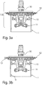
- FIG. 3a the clamping module is illustrated in a partial longitudinal sectional view in a relaxed state within a support tube 1.
- FIG. 3b shows a corresponding partial longitudinal sectional view of the clamping module 5.2 in a tensioned state, are placed in the friction elements 10 kraftbeaufschlagt in radial engagement with the pipe inner wall 1i.
- the clamping module 5.2 can, as from the FIGS. 3a and b can be used over the front end of the pipe socket 1 in the interior of the pipe socket 1, wherein guide rollers 11 simplify the threading of the clamping module 5.2 in the pipe socket 1.
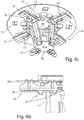
- the clamping module 5.2 on a support platform 12 which is annular plate-shaped and has a pipe socket 1 facing bottom 13, are distributed to the ring circumferentially equally distributed support elements 14 (see FIGS.
- each having a radial extent, along which at least partially an electrically insulating element 15 is attached, is ensured by the thermal and in particular electrical insulation of the clamping module 5.2 to the pipe socket 1 to isolate welding currents relative to the clamping module.
- the front end of the pipe socket 1 comes to rest on the electrically and preferably thermally insulating elements 15 of the support elements 14, which define the abutment plane 16 of the support platform 12.
- the support elements 14 each have a radial extent, which is dimensioned such that the front ends of the pipe socket come to rest respectively with differently dimensioned pipe inner diameter or outer diameter on the support elements 14 in centric alignment of the annular plate-shaped support platform 12 relative to the pipe socket. Radially along each support element 14 are provided for purposes of easier Grobzentri proceedings the support platform 12 relative to the front end of the pipe socket 1 spacers 17, which can be positioned radially according to the pipe dimensions.
- guide rollers 11 are mounted, which simplify the threading process of the clamping module to be explained below in the respective pipe socket.
- four guide rollers 11 are provided, which are connected for mutual stabilization via a common connection plate 19, which occupies a fixed predetermined distance from the support platform 12.
- the annular plate-shaped support platform 12 has a central opening through which, as will be explained below, a motor-driven spindle mechanism protrudes, for driving a friction elements 10 radially deflecting lever mechanism, see Fig. 4c , d.
- the outer ring diameter of the support platform 12 is in each case dimensioned larger than the pipe outer diameter of the pipe socket 1, so that the bearing elements 14 mounted on the underside 13 of the support platform 12 also have a greater radial extent than the outer diameter of each pipe socket to be joined.
- the friction element assembly 20 each includes a guide rail 21, along which a slide 22 is mounted bidirectionally deflectable, on which the friction element 10 is mounted.
- the guide rail 21 extends as it were the support elements 14 radially to the pipe socket axis and is mounted relative to the contact plane 16 inclined to the support platform 12.
- the guide rail 21 is inclined relative to the abutment plane 16 by an angle ⁇ , for which is 0 ° ⁇ ⁇ 10 °, preferably 5 °.
- All Reibelementan glovesen 20 are each connected to an actuator designed as a lever actuator in operative connection through which the Friction element assemblies 20 from a first position in which the Reibelementan extracten 20 each occupy a distance from the pipe inner wall of the pipe socket can be converted into a second position in which the Reibelementan extracten each have a relation to the first distance greater second distance from the axis, so that the friction elements 10th the respective friction element assemblies 20 each form a force and frictional engagement with the pipe inner wall.
- the passing with the pipe inner wall 1i in contact friction elements 10 can be exchanged for adaptation to the inner diameter of the respective pipe socket 1.
- the friction elements 10 are made of the same insulating material as the insulating elements 15 along the support elements 14.
- the carriage 22 is dimensioned and formed so that the friction elements 10, which come into contact with the pipe inner wall 1i, have a certain axial distance to the guide rail 21 and thus also an axial distance to the front-side open end of the pipe socket in the joined state ,
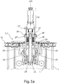
- FIGS. 5 a . b For radial deflection of the Reibelementanssenen 20 is a common actuator unit, which is in each case via a lever mechanism with the individual Reibelementan effet 20 in operative connection.
- common actuator unit is on the FIGS. 5 a . b directed.
- FIG. 5a shows a longitudinal section through a self-contained in a pipe socket clamping module 5.2.
- FIG. 5b shows the common actuator unit with the lever mechanism in solo view.
- the further descriptions relate equally to both representations. So the sled 22 is everyone Friction element assembly 20 hingedly connected to a coupling member 23 (see also Figure 4c .
- each guide rod 28 is connected on one side, on the other hand articulated on a spindle nut 24 which is guided along a spindle 25.
- the spindle 25 is connected to a drive motor 26 at its upper spindle end.
- the motor 26 is connected via a holding frame 27 'fixed to a motor plate 27, projecting through the four guide rods 28 each slidably.
- the sliding support of each guide rod 28 is realized by a ball sleeve 27 "integrated in the motor plate 27.
- the guide rods 28 are fixedly connected at their lower rod ends to the connection plate 19.
- a spring element 30 preferably in the form of a disc spring package, which supports the motor 26 together with the holding frame 27 'and motor plate 27.
- the guide rods 28 likewise project through the base plate 29 in a sliding manner.
- the spindle nut 24 is moved vertically upward with suitable rotation of the spindle 25, whereby the carriage 22 of the Reibelementan extract 20 by means of the coupling members 23 are moved radially outwardly to engage the pipe wall 1i.
- the length of the individual coupling members 23 is preferably dimensioned such that in the clamped state, the coupling members 23 with the spindle longitudinal axis 25 S form an angle, preferably between 80 ° and 85 °. In order to ensure this angle for different pipe socket inner diameter, the lengths of the individual coupling members 23 can be adjusted. In a preferred embodiment for the realization of the coupling elements 23, these exist, see FIG.
- the mechanical clamping energy cached in the plate spring assembly 30 ensures compensation of the thermal pipe socket expansion by kraftbeetztes tracking the carriage 22 against the pipe socket inner wall.
- the drive motor 26 which is typically not designed as a servomotor, proximity or limit switches are used to ensure that the motor moves as far until the plate spring package 30 is stretched to the desired extent. The drive motor gets so after triggering the limit switch a signal and is then stopped. In the case of the formation of the drive motor 26 as a servomotor can be dispensed with the limit switch, yet to ensure that the spindle 25 can be driven position-controlled motor.
- the carrier ring module 5.1 is mounted on the top of the support platform 12.
- the support ring module 5.1 has a fixed to the support platform 12 connected ring member 31 on which the support ring module 5.1, preferably via a rolling bearing W is rotatably mounted, see also Fig. 4d ,
- FIG. 6 shows a perspective view of the carrier ring module 5.1 from below.
- a drive wheel 32 'of a fixed to the support ring module 5.1 connected servo motor 32 is engaged.
- the support ring module 5.1 has two fixedly connected via a bracing structure 33 support ring plates 34.1 and 34.2, at the peripheral edge of each two peripherally flattened contact portions 35 are provided, which are diametrically opposed to the peripheral edge of both support ring plates 34.1, 34.2 and to each of which a holding device 9, not in FIG. 6 shown, see Fig. 2a, b , is mounted for the attachment of each of a linear support structure 8.
- the diameter of the carrier ring module 5.1 should correspond approximately to the pipe socket diameter, d. H. at least by not too great a degree to keep the radial extent over the pipe socket as low as possible so as to weld pipe socket constellations can, in which the pipe socket longitudinal axis with the main pipe longitudinal axis forms an angle less than 45 °.
- the along the holding device 9 bidirectionally guided linear support structure 8, see Fig. 2a, b such as Fig. 7a, b, c is composed in an advantageous embodiment of three parallel longitudinal struts 36 together, each of which may have a length of several meters, ie up to 3 to 5 m, see FIGS. 2a, b .
- the Figure 7a shows a single representation of a linear support structure 8
- FIG. 7b shows a single view of a holding device 9
- FIG. 7c shows a cross section through a holding device 9 with an inner linear support structure. 8
- the three longitudinal struts 36 of the linear support structure 8 are firmly connected to one another via an internal truss structure 37, for example by means of gluing, and thus form a rigid structural structure which superimposes loads in the way Vertical and horizontal movements can be withstood without significant deformations. Also runs parallel to the longitudinal struts 36 a driven by means of a drive motor 38 spindle 39, in engagement with a spindle nut 39 ', see FIG. 7c is, which is firmly connected to the holding device 9.
- the longitudinal struts 36 are slidably guided along the support structure 9, so that the entire linear support structure 8 can be moved bidirectionally by the explained spindle drive, ie in the sense of FIGS.
- the three longitudinal struts 36 which at the same time serve as guide rails, run through half-opened ball bushings 40, which are integrated in the holding device 9, so that the stiffening framework structure 37 can be moved without collision to the holding device 9.
- the construction is very easy and also opens the possibility to lead cables, welding wire or other supply lines 41 through the stiffening structure of the linear support structure 8.
- the mentioned manipulator unit 7 is mounted, which is supplied via both the power supply and material attached to the linear structure 8, which is required for the welding operation. In the case of in FIG.
- the supply units 42 are attached to the lower end of the linear support structure 8, in the case of in Figure 7a illustrated embodiment at the upper end of the supporting structure 8.
- the manipulator unit 7 is preferably formed as a six-axis vertical articulated robot, the fine welding tool 6 attached thereto using appropriately provided sensors against the three-dimensional Verschneidungskurve 3 along the pipe socket.
- a sensor unit 54 for contact-free detection of the shape and / or size of an interspace along the intersecting curve or a groove-shaped recess, which is or to fill in the way of welding.
- the sensor unit 54 is designed as a line-cutting sensor with which the real cross-section of the weld seam to be filled is measured prior to welding each weld layer. Based on this information, the path planning and then how the next welding position is placed in the corresponding weld cross-section.
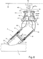
- FIG. 8 illustrated schematically, in which the welding assembly 4 is frontally attached to a pipe socket 1, the tube longitudinal axis is inclined relative to the tube longitudinal axis of a base tube 2 by 45 °.
- the welding arrangement 4 has two welding tools 6 attached to the carrier ring module 5.1, which faces the three-dimensional intersection curve 3 and is attached at each end to the linearly movable structures 8 which are articulated on the carrier ring module 5.1.
- the suspension device 52 for the supply module 43 on the support structure 44 allows both a vertical (z-axis) and horizontal (x, y-axis) positioning as well as a rotation of the supply module 43 about the vertical axis (z-axis).
- the supply module 43 has a module carrier 45, on which all logistics components relevant for the welding process are accommodated. These relate per welding tool in each case a control unit 46.1, 46.2 a welding wire storage with corresponding motor wire feed 47.1, 47.2.
- the power supply of the separate supply module, in particular the control units 46.1 and 46.2 is preferably carried out via an external Cable feed 48, which connects via a centrally arranged on the supply module 43 slip ring coupling 49. If necessary, a further external supply line 50 is provided, via which welding gas is supplied to the supply module 43.
- the connection of the welding gas supply 50 to the supply module 43 also takes place via a fluid-tight slip ring coupling 49 '. In this way, external energy sources as well as gas reservoirs, for example. In the form of gas cylinders, stored in easily accessible places in the region of the pipe node and used accordingly.
- connection lines 51 are provided, via which ultimately the welding tools are supplied with energy as well as the materials required for the welding process.
- the module carrier 45 of the supply module 43 in a suitable manner on the support structure 44, which is formed, for example. Galgenförmig or in the manner of a three- or four leg and the welding assembly 4 together with the pipe socket to be welded vertically projecting, spatially freely positioned suspended and in particular to the Vertical axis z rotatably mounted.
- the supply module 43 serves by means of the stable and load-carrying trained module carrier 45 as a kind of crane element to which the welding assembly 4 is integrally releasably attached. With the help of mounted on the module carrier 45, motor-driven pulleys 53 to run the cables, the welding assembly 4 can be discharged for assembly purposes and raised for disassembly purposes.
- the described welding arrangement it is thus possible to weld pipe sockets of any diameter and angle between the base pipe and pipe socket.
- the problem of a collision between welding manipulator and pipe socket is not or hardly given.
- the novel welding arrangement is much less expensive than portal-based, inevitably stationary welding systems and also easy to scale in terms of processing time due to the modular structure.
- two, three or more welding tools can be fastened to the support edge module via respective linear supports, as a result of which the required welding time can be significantly reduced.
- Another important advantage is the compactness of the welding arrangement. While portal-based solutions are tied to the machining site, the solution weld assembly can be brought to the pipe node and welded on site.
Landscapes
- Engineering & Computer Science (AREA)
- Physics & Mathematics (AREA)
- Mechanical Engineering (AREA)
- Optics & Photonics (AREA)
- Plasma & Fusion (AREA)
- Butt Welding And Welding Of Specific Article (AREA)
- Manipulator (AREA)
- Arc Welding In General (AREA)
- Lining Or Joining Of Plastics Or The Like (AREA)
Description
- Die Erfindung bezieht sich auf eine Schweißanordnung zum dauerhaften Fügen eines ersten rohrförmigen Bauteils mit einem zweiten Bauteil längs einer zwei- oder dreidimensionalen Verschneidungskurve, längs der sich beide Bauteile berühren, mit einer Befestigungsanordnung zum lösbar festen Fügen an einem der Verschneidungskurve abgewandten rohrförmigen Ende des ersten Bauteils, einer mittel- oder unmittelbar an der Befestigungsanordnung um eine dem ersten Bauteil zugeordneten Rohrlängsachse schwenkbar gelagerten Manipulatoreinheit mit einem frei positionierbaren Manipulatorende, sowie einem an dem frei positionierbaren Manipulatorende angebrachten Schweißwerkzeug.
- Der Ausbau erneuerbarer Energiequellen führt zu einem wachsenden Bedarf an Offshore-Windenergieanlagen, zu deren Befestigung am oder im Meeresboden Ressourcen schonende Gründungsstrukturen in Form so genannter Jackets, Tripiles oder Tripods erforderlich sind, die sich allesamt durch Baustahlrohr-Konstruktionen mit Rohrknoten auszeichnen, die stahlbauliche Verbindungselemente von sich kreuzenden Rohren darstellen. Aufgrund verschiedener Typen von Gründungsstrukturen kommen unterschiedliche Rohrknoten in X-, Y-, K- und doppel-K-Bauweise zum Einsatz. Innerhalb dieser Bauweise unterscheiden sich die Rohrknotenverbindungen in Anschlusswinkel, Positionierung der Rohrstutzen, Baustahlrohrdicken sowie auch Durchmesser, so dass eine sehr große Anzahl verschiedener Knotentypen auch innerhalb einer Gerüstkonstruktion zum Einsatz kommen kann. Die Verbindung zweier Baustahlrohre, zumeist handelt es sich hierbei um die Verbindung eines Rohrstutzens an ein im Durchmesser größer bemessenes Basisrohr, erfolgt aufgrund der hier relevanten Dimensionen durch Schweißen. Dabei sind die Nahtvorbereitung sowie ein möglichst genauer Zuschnitt beider miteinander zu fügenden Rohrbauteile längs der dreidimensionalen Verschneidungskurve, längs der sich beide Bauteile berühren, von zentraler Bedeutung für die Schweißnahtqualität sowie Maßhaltigkeit.
- Sowohl die Nahtvorbereitung als auch der Schweißfügeprozess von Rohrknotenverbindungen erfolgt in den häufigsten Fällen aufgrund der großen Abmessungen und Massen der beteiligten Fügepartner manuell, wodurch die Fertigung langwierig, ineffizient und teuer ist. Problematisch für den Einsatz von Schweißautomaten für die Herstellung derartiger Rohrknoten ist die große Menge an unterschiedlichen Rohrverbindungen, die bisher nicht mit einer einzigen automatisierten Universalschweißanordnung bewältigt werden kann.
- In diesem Zusammenhang offenbart die Druckschrift
DE 33 13 230 A1 ein Verfahren sowie eine Vorrichtung zum automatischen Anschweißen eines Rohrstutzens an ein größeres Basisrohrelement, letzteres ist dazu drehbar gelagert. Nach Anheften des Rohrelementes an das Basisrohr wird am Rohrstutzen eine Befestigungsanordnung angebracht, an der drehbar um die Rohrlängsachse des Rohrstutzens eine Schweißarmanordnung angelenkt ist, die zusätzlich zur Drehbewegung um die Rohrlängsachse axial bidirektional auslenkbar ist, um so ein Schweißwerkzeug exakt längs der dreidimensionalen Verschneidungskurve verfahren zu können. Aufgrund der Ausmaße der bekannten, am Rohrstutzen anzubringenden Schweißanordnung eignet sich diese lediglich zum Fügen von Rohrstutzen an einem Basisrohrabschnitt mit jeweils orthogonal zueinander orientierten Rohrachsen. - Die bekannte Vorrichtung nutzt zum einen den Vorteil, dass durch die drehbare Lagerung des Basisrohrabschnittes der Schweißvorgang stets in so genannter "Wannenlage" erfolgt, wodurch eine größtmögliche Schweißgeschwindigkeit und eine sehr hohe Schweißqualität erzielt werden kann, gleichwohl besteht der Nachteil, dass das Handling der zu fügenden Rohrbauteile aufgrund deren Größe und Gewicht begrenzt ist, eingedenk der Tatsache, dass insbesondere beim Fertigen von Offshore-Plattformen Rohrknoten mit einem Gesamtgewicht von 30 Tonnen und mehr sowie Rohrlängen von typischerweise bis zu 10 Metern und Durchmessern in der Größenordnung von 1 bis 3 Metern handzuhaben sind. Darüber hinaus werfen Rohrknoten mit Rohrwinkelkonstellationen, bei denen die Rohrlängsachse des anzuschweißenden Rohrstutzens relativ zur Rohrlängsachse des Basisrohres einen Winkel kleiner 90°, vorzugsweise kleiner 45° einschließt, Raumprobleme dahingehend auf, dass ein freies Verdrehen des Schweißwerkzeuges um 360° um die Rohrlängsachse des anzuschweißenden Rohrstutzens aufgrund der radial ausladenden Bauweise nicht möglich ist.
- Sehr ähnliche Schweißvorrichtungen zum Fügen zweier rohrförmiger Bauteile, deren Rohrlängsachsen jeweils orthogonal zueinander orientiert sind, sind in den folgenden Druckschriften offenbart:
EP 0060382 A1 ,EP 1811047 A1 ,JP 60203370 A DE 10 2009 043 021 B3 ,DE 30 05 153 A1 sowieEP 0133411 A1 . - Die Druckschrift
DE 10 2011 118 615 A1 beschreibt eine Vorrichtung zum Schweißen eines Rohrstutzens längs eines Basisrohrabschnittes, deren Rohrachsen einen spitzen Winkel einschließen. Zum Schweißen beider Rohrteile längs der dreidimensionalen Verschneidungskurve ist ein an einer Linearachse bidirektional auslenkbarer Schweißroboter angebracht, der jedoch nur einen Teilabschnitt der Verschneidungskurve zu bearbeiten vermag. Zum vollständigen Verschweißen sind wenigstens zwei, vorzugsweise drei derartiger Schweißroboter um die miteinander zu fügenden Rohrbauteile anzuordnen. - Die Druckschrift
EP 2 311 595 A1 beschreibt ein Unterpulver-Schweißgerät zum Verbinden zweier Werkstücke längs einer gemeinsamen Verschneidungskurve, wobei das Schweißgerät samt der für den Schweißprozess erforderlichen Komponenten, wie Schweißdrahtzuführung, Steuergerät auf einer Plattform montiert sind, die gemeinsam mit dem Schweißwerkzeug um eine Achse drehbar angeordnet sind, um die das Schweißwerkzeug zum Schweißen längs der vollständigen Schweißnaht gedreht wird. Die Anordnung ist geeignet zum Schweißen zweier Rohrstücke, deren Rohrlängsachsen senkrecht zueinander orientiert sind. - Eine zur vorstehenden Schweißanordnung vergleichbare Schweißanordnung ist der Druckschrift
EP 0 049 037 A1 zu entnehmen, mit der die Herstellung einer Schweißverbindung zweier Rohrstücke möglich ist, deren Rohrlängsachsen orthogonal zueinander orientiert sind. Die Schweißanordnung ist an ein kleineres Rohrstück, das vertikal zu einem im Durchmesser größeren Rohrstück orientiert ist, abnehmbar fest gefügt und vermag Drehungen um die Rohlängsachse auszuführen, während eine vertikal absenkbare Schweißdüse einen Spalt zwischen beiden Rohrstücken im Wege des Schweißprozesses zu schließen vermag. Auch in diesem Fall sind sämtliche für den Schweißprozeß erforderlichen Komponenten auf der drehbar angeordneten Schweißanordnung angeordnet. - Aus der Druckschrift
JP 57195583 A - Aus der Druckschrift
JP 2005-219124 A - Der Erfindung liegt die Aufgabe zugrunde, eine Schweißanordnung zum dauerhaften Fügen eines ersten rohrförmigen Bauteils mit einem zweiten, vorzugsweise ebenfalls rohrförmigen Bauteil längs einer zwei- oder dreidimensionalen Verschneidungskurve, längs der sich beide Bauteile berühren, mit einer Befestigungsanordnung zum lösbar festen Fügen an einem der Verschneidungskurve abgewandten rohrförmigen Ende des ersten Bauteils, einer mittel- oder unmittelbar an der Befestigungsanordnung um eine dem ersten Bauteil zugeordneten Rohrlängsachse schwenkbar gelagerten Manipulatoreinheit mit einem frei positionierbaren Manipulatorende sowie einem an dem frei positionierbaren Manipulatorende angebrachten Schweißwerkzeug derart weiterzubilden, dass die Schweißanordnung möglichst flexibel, kompakt und leicht ausgebildet sein soll, um Schweißaufgaben insbesondere zur Herstellung von Rohrknoten vor Ort durchführen zu können, ohne dass die beteiligten Fügepartner einer gesonderten Lagerung bedürfen. Insbesondere soll es möglich sein, beliebige Rohrknotenkonstellationen zu schweißen, mit wenigstens einem Rohrstutzen, dessen Rohrlängsachse mit der Rohrlängsachse eines Basisrohrabschnittes einen spitzen Winkel einschließt von 45° und weniger. Die Schweißanordnung soll darüber hinaus die Möglichkeit eröffnen, wenigstens ein Schweißwerkzeug um wenigstens 360° um die Rohrlängsachse des Rohrstutzens zu verschwenken, vorzugsweise unendlich oft um die Rohrlängsachse zu verschwenken, um auf diese Weise zumindest eine vollständig durchgängige, homogene Schweißnaht längs der Verschneidungskurve ausbilden zu können und dies ohne die Gefahr einer Kollision mit umliegenden Rohrwandbereichen. Durch unendliche Drehungen des Schweißwerkzeuges um die Rohrlängsachse soll es zudem möglich sein, große Wandstärken mit bis zu mehreren Zentimetern Dicke und einem damit verbundenen großen Schweißnaht-Füllvolumen mit einander zu schweißen. Hierbei sollen durch beliebig häufiges Überfahren der Schweißnaht mehrere einzelne, sogenannte Schweißraupen das Schweißnaht-Füllvolumen vollständigen füllen. Ferner soll die Schweißanordnung ohne weiteren montagetechnischen Aufwand an Rohrstutzen lösbar fest anbringbar sein, deren Rohrdurchmesser sich jeweils unterscheiden.
- Die Lösung der der Erfindung zugrunde liegenden Aufgabe ist im Anspruch 1 angegeben. Vorteilhafte Weiterbildungen sind Gegenstand der Unteransprüche sowie der weiteren Beschreibung unter Bezugnahme auf die Figuren zu entnehmen.
- Lösungsgemäß zeichnet sich eine Schweißanordnung zum dauerhaften Fügen eines ersten rohrförmigen Bauteils mit einem zweiten Bauteil längs einer zwei- oder dreidimensionalen Verschneidungskurve, längs der sich beide Bauteile berühren, mit den Merkmalen des Oberbegriffes des Anspruches 1 derart aus, dass die Manipulatoreinheit eine 6-achsige offene kinematische Kette in Form eines vertikalen Knickarmroboters ist und an einem Ende des Tragwerks angebracht ist. Ferner ist ein Versorgungsmodul vorgesehen, an dem wenigstens eine der folgenden Komponenten angebracht ist: eine Steuereinheit, eine elektrische Energieversorgungseinheit, wenigstens ein Reservoir für den Schweißprozeß relevante Materialien, umfassend Schweißdraht und Prozessgas. Wenigstens eine der vorstehenden Komponente ist über eine Verbindungsleitung mit dem Schweißwerkzeug verbunden, wobei das Versorgungsmodul drehbar gelagert ist, so dass es zur Bewegung des Schweißwerkzeugs um die Rohrlängsachse simultane Drehbewegung ausführen kann, um unendlich viele Drehungen des Schweißwerkzeuges um die Rohrlängsachse zu ermöglichen. Das Versorgungsmodul ist an einer zur Schweißanordnung separat ausgebildeten Tragstruktur zumindest längs einer Ebene frei positionierbar angelenkt.
- Unter dem Begriff "Manipulatoreinheit" ist eine kinematische Kette zu verstehen, die ein System aus starren Körpern vorsieht, die durch Gelenke verbunden sind. Die Gelenke können dabei unterschiedliche Freiheitsgrade haben. Die Gelenke können sowohl als Drehgelenke mit wenigstens einer Drehachse, als auch als Schiebe- oder Schubgelenke ausgebildet sein. Die kinematische Kette im Falle der Schweißanordnung ist als eine 6-achsige, offene kinematische Kette in Form eines vertikalen Knickarmroboters ausgebildet.
- Die Schweißanordnung stützt sich mit ihrer Befestigungsanordnung ausschließlich am rohrförmigen ersten Bauteil ab. Hierzu wird das der Befestigungsanordnung zugeordnete Klemmmodul stirnseitig in das einseitig offen ausgebildete, erste rohrförmige Bauteil axial eingesetzt. Im Wege einer darauffolgenden radialen Spreizung des Klemmmoduls geht die Befestigungsanordnung mit der Rohrinnenwand eine axial feste und verdrehsichere Kraft- und Reibschlussverbindung ein. Das Klemmmodul tritt hierbei über radial auslenkbare Reibelemente mit der Rohrinnenwand des ersten rohrförmigen Bauteils in Wirkverbindung, wobei die radiale Ausstellung der einzelnen Reibelemente variabel vorgenommen werden kann, so dass je nach Ausgestaltung und Dimensionierung eines die Reibelemente radial austellenden, aktorisch angetriebenen Hebelmechanismus ein und das gleiche Klemmmodul zur Befestigung an rohrförmigen Bauteilen mit jeweils unterschiedlichen Rohrinnendurchmessern eingesetzt werden kann, die sich bspw. bis zu einem Meter voneinander unterscheiden können.
- In einer bevorzugten Ausführungsform verfügt die Befestigungsanordnung über eine mechanische Energiespeichereinheit, die die seitens des aktorisch angetriebenen Hebelmechanismus erzeugte radial wirkende Klemmkraft derart unterstützt, so dass bei einer thermisch bedingten radialen Aufweitung des ersten rohrförmigen Bauteils, wie dies in Fällen eines lang andauernden Schweißprozesses der Fall sein kann, die Reibelemente entsprechend kraftbeaufschlagt radial nachgeführt werden, wodurch die radiale Klemmkraft aufrechterhalten wird und auf diese Weise stets ein sicherer Halt der Schweißanordnung am jeweils ersten rohrförmigen Bauteil gewährleistet ist.
- Das Klemmmodul ist ferner mit einer Abstützplattform verbunden, die mittel- oder unmittelbar in Anlage an das axial stirnseitige, rohrförmige Ende des ersten Bauteils bringbar ist und für eine axiale Abstützung der Befestigungsanordnung an dem ersten Bauteil sorgt. Zudem dient die Abstützplattform zur Aufnahme des Trägerringmoduls, das gegenüber der Abstützplattform axialfest und drehbar um eine Drehachse gelagert ist, die im gefügten Zustand des Klemmmoduls innerhalb des ersten rohrförmigen Bauteils mit der Rohrlängsachse zusammenfällt.
- Zur drehbaren Lagerung des Trägerringmoduls relativ zur Abstützplattform weist das Trägerringmodul vorzugsweise wenigstens einen Trägerring auf, der einen drehbar zum Trägerring angeordneten Ringteil besitzt, der axial und drehfest mit der Abstützplattform lösbar fest verbunden ist. Zur drehbeweglichen Auslenkung des wenigstens einen Trägerringes relativ zum fest mit der Abstützplattform verbundenen Ringteil dient ein Servomotor, der einerseits fest mit dem Trägerring verbunden ist und andererseits über einen Getriebemechanismus mit dem Ringteil in Eingriff steht.
- Der wenigstens eine Trägerring des motorisch relativ zum Klemmmodul drehbar angeordneten Trägerringmoduls verfügt in vorteilhafter Weise über einen kreisförmig ausgebildeten peripheren Umfangsrand, längs dem wenigstens eine Haltevorrichtung angebracht ist, die mit einem linearen Tragwerk derart in Eingriff steht, so dass das lineare Tragwerk aktorisch angetrieben, relativ zur Haltevorrichtung längs einer Linearachse bidirektional auslenkbar ist. Im Falle eines in das erste rohrförmige Bauteil eingesetzten Klemmmoduls erstreckt sich die Linearachse des linearen Tragwerks parallel zur Rohrlängsachse des rohrförmig ausgebildeten ersten Bauteils, wobei das lineare Tragwerk einen möglichst minimalen radialen Abstand zur Außenwand des ersten rohrförmigen Bauteils einnimmt. Wie die weiteren Ausführungen zeigen werden, ist der aktorische Antrieb des linearen Tragwerkes durch einen motorisch angetriebenen Spindelmechanismus realisiert, der zur kontrollierten bidirektionalen Auslenkung des linearen Tragwerkes in Eingriff mit der am Trägermodul angebrachten Haltevorrichtung steht. Das lineare Tragwerk besteht vorzugsweise aus einer fachwerkartig ausgebildeten Versteifungskonstruktion, die über eine sehr hohe Steifigkeit und damit verbunden über eine sehr geringe statische Durchbiegung verfügt. Das lineare Tragwerk kann bis zu 4 Meter Länge aufweisen, an dessen einseitigem Ende die Manipulatoreinheit in Form einer kinematischen Kette, nämlich in Form eines 6-achsigen, vertikalen Knickarmroboters, zur weiteren Raumpositionierung des am freien kinematischen Kettenende angebrachten Schweißwerkzeuges angeordnet ist. Der räumlich kleinbauende Knickarmroboter weist ein Eigengewicht von unter 100 kg, vorzugsweise ca. 60 kg auf, und ist somit räumlich frei verschwenk- und positionierbar. Auf diese Weise lassen sich der Knickarmroboter sowie das an diesem angebrachte Schweißwerkzeug möglichst enganliegend an der Außenwand des Rohrstutzens vollständig um den Rohrstutzen verschwenken, so dass eine kontinuierliche Schweißnahtausbildung längs der Fügekontur ohne Kollision mit umgebenden Wandteilen möglich ist.
- Vornehmlich aus Gründen der drehbeweglichen Lagerung des Schweißwerkzeuges um das fest innerhalb des Rohrstutzens gefügte Klemmmodul derart, so dass das Schweißwerkzeug mit einheitlicher Drehrichtung mehrfach um die Rohrachse des Rohrstutzens zur Ausbildung einer unterbrechungsfrei, vollständig umlaufenden Schweißnaht, die sich u.U. aus mehrlagigen Schweißlagen zusammensetzt, gedreht werden kann, gilt es für eine kontinuierliche Energie- und Materialversorgung für das Schweißwerkzeug und die Manipulatoreinheit zu sorgen. Eine bevorzugte Ausführungsform sieht hierzu ein Versorgungsmodul in Form einer konstruktiv eigenständigen Baueinheit vor. Das Versorgungsmodul verfügt hierzu über einen Modulträger, an dem sämtliche Versorgungseinheiten für das Schweißwerkzeug angebracht sind, bspw. eine Steuereinheit zur Aktivierung und Ansteuerung des Schweißwerkzeuges, eine elektrische Energieversorgungseinheit sowie wenigstens ein Reservoir für den Schweißprozeß relevante Materialien, wie bspw. Schweißdraht, Prozessgas etc..
Die einzelnen Versorgungseinheiten sind über entsprechende Verbindungsleitungen mit dem Schweißwerkzeug verbunden. Um zu vermeiden, dass drehbedingte Komplikationen längs der Verbindungsleitungen auftreten, gilt es die Versorgungseinheit synchron mit dem Schweißwerkzeug mitzudrehen. - In einer bevorzugten lösungsgemäßen Ausführungsvariante ist das Versorgungsmodul getrennt zur Schweißanordnung an einer separaten Tragstruktur drehbar gelagert. Die Tragstruktur überragt vorzugsweise die zu schweißenden Rohrteile, so dass das Versorgungsmodul räumlich verfahr- und drehbar an der Tragstruktur befestigt ist und räumlich bewegt werden kann. Vorzugsweise kann die Tragstruktur mit dem daran angebrachten Versorgungsmodul auch zur Montage sowie Demontage der Schweißanordnung an den Rohrstutzen genutzt werden.
- Die lösungsgemäß ausgebildete Schweißanordnung ermöglicht in bevorzugter Weise das Zusammenfügen so genannter Rohrknoten, bei denen Rohrstutzen mit nahezu beliebigem Durchmesser an ein Basisrohr zu schweißen sind, wobei die Rohrstutzen unter nahezu beliebige Winkel relativ zur Rohrlängsachse des Basisrohres angeordnet sein können. Eine mögliche Problematik der Kollision zwischen der Schweißanordnung und dem Rohrstutzen kann ausgeschlossen werden, zumal die Schweißanordnung kompakt und kleinbauend realisierbar ist. Durch den modularen Aufbau der lösungsgemäßen Schweißanordnung können zwei, drei oder mehr lineare Tragwerke mit jeweils daran befestigten Manipulatoreinheiten und den daran angebrachten Schweißwerkzeugen am Trägerringmodul befestigt werden, wodurch die für ein gesamtheitliches Schweißen eines Rohrstutzen an einem Basisrohr erforderliche Schweißzeit erheblich reduziert werden kann.
- Die Erfindung wird nachstehend ohne Beschränkung des allgemeinen Erfindungsgedankens anhand von Ausführungsbeispielen unter Bezugnahme auf die Zeichnungen exemplarisch beschrieben. Es zeigen:
- Fig. 1
- Perspektivische Gesamtdarstellung der lösungsgemäß ausgebildeten Schweißanordnung an einem Rohrknoten,
- Fig. 2a, b
- Anordnungen der Schweißanordnung innerhalb eines Rohrknotens mit a) kleinem Durchmesser und b) größerem Durchmesser,
- Fig. 3a, b
- Darstellung des Klemmmechanismus in a) entspannter Stellung und b) verspannter Stellung mit der Rohrinnenwand,
- Fig. 4a, b, c
- Detaildarstellungen zum Klemmmodul:
- a) illustrierte perspektivische Schrägansicht auf die Unterseite der Abstützplattform
- b) Teillängsschnittdarstellung durch die Abstützplattform des Klemmmoduls,
- Fig. 5a, b
- Darstellungen des Klemmmoduls,
- Fig. 6
- Ansicht des Trägerringmoduls,
- Fig. 7a-c
- a) Darstellung des linearen Tragwerks, b) der Haltevorrichtung sowie c) Querschnittdarstellung durch Haltevorrichtung mit Tragwerk und
- Fig. 8
- Schweißanordnung mit einem an einer Tragstruktur angebrachtem Versorgungsmodul.
-
Figur 1 zeigt eine schematisierte Darstellung eines Rohrknotens mit einem als erstes rohrförmiges Bauteil 1 bezeichneten Rohrstutzen, der einseitig stirnseitig mit einem zweiten rohrförmigen Bauteil 2, im Weiteren Basisrohr, längs einer dreidimensionalen Verschneidungskurve 3 mittels Schweißtechnik verbunden ist bzw. wird. Das Basisrohr 2 weist gegenüber dem Rohrstutzen 1 einen größeren Rohrdurchmesser auf. Selbstverständlich ist es möglich, dass die Rohrdurchmesser von Rohrstutzen und Basisrohr gleich bemessen sind. Der in derFigur 1 illustrierte Rohrstutzen 1 weist eine Rohrlängsachse 1R auf, die mit der Rohrlängsachse 2R des Basisrohrs 2 einen Winkel kleiner 90°, vorzugsweise ≤ 45° einschließt. - Der schweißtechnische Fügevorgang, mit dem der Rohrstutzen 1 mit dem Basisrohr 2 verbunden wird, erfolgt mit Hilfe der ausschließlich am Rohrstutzen 1 befestigten Schweißanordnung 4, d.h. für den Schweißvorgang ist auch eine gesonderte Lagerung des Basisrohrs 2 nicht erforderlich. Die Schweißanordnung 4 stützt sich ausschließlich am Rohrstutzen 1 ab und ermöglicht die räumliche Positionierung bzw. Führung des Schweißwerkzeuges 6 um den Rohrstutzen 1 in räumlich unmittelbarer Nähe zur und längs der dreidimensionalen Verschneidungskurve 3. Hierzu ist das Schweißwerkzeug 6 am kinematischen Ende einer Manipulatoreinheit 7 angebracht, die vorzugsweise in Form eines gelenkig ausgebildeten Roboterarms, vorzugsweise eines 6-achsigen vertikalen Knickroboterarms, ausgebildet ist. Die Manipulatoreinheit 7 ermöglicht die räumliche Feinpositionierung des Schweißwerkzeuges 6 längs und um wenigstens sechs Achsen. Die Manipulatoreinheit 7 ihrerseits ist endseitig an einem linearen Tragwerk 8 befestigt, das über eine Haltevorrichtung 9 mit einer Befestigungsvorrichtung 5 verbunden ist. Das lineare Tragwerk 8 ist motorisch bidirektional längs seiner Längserstreckung relativ zur Haltevorrichtung 9 auslenkbar gelagert.
- Die Befestigungsvorrichtung 5 sorgt für eine sichere lösbar feste Lagerung der gesamten Schweißanordnung ausschließlich am Rohrstutzen 1. Hierzu weist die Befestigungsanordnung 5 ein motorisch drehbar angetriebenes Trägerringmodul 5.1 auf, das eine vollständige Umfahrung des Schweißwerkzeuges 6 um die Rohrachse 1R des Rohrstutzens 1 und somit längs der vollständigen Erstreckung der dreidimensionalen Verschneidungskurve 3 ermöglicht. Das Trägerringmodul 5.1 ist mit einem nicht in
Figur 1 ersichtlichen Klemmmodul 5.2 verbunden, das mittels eines Spreizmechanismus gegen die Rohrinnenwand des Rohrstutzens 1 für einen lösbar festen Sitz sorgt und die gesamte Schweißanordnung an Rohrstutzen 1 abstützt. Die lösungsgemäße Schweißanordnung 4 zeichnet sich durch ihren kompakten und eng am Rohrstutzen 1 anliegenden Aufbau aus, der eine räumliche Positionierung des Schweißwerkzeuges 6 selbst in räumlich beengten Fügebereichen ermöglicht. Nur der Vollständigkeit halber sei erwähnt, dass der inFigur 1 illustrierte Rohrknoten 2 über weitere Rohrstutzen 1', 1" verfügt, von denen der Rohrstutzen 1' eine orthogonale Achsausrichtung sowie der weitere Rohrstutzen 1" eine spitzwinklige Rohrachsenausrichtung relativ zur Rohrachse 2R besitzt. Die lösungsgemäße ausgebildete Schweißanordnung ermöglicht aufgrund ihres kompakten und modularen Aufbaus das schweißtechnische Fügen von nahezu beliebig geneigten und dimensionierten Rohrstutzen an jeweils ein als zweites, vorzugsweise rohrförmiges Bauteil bezeichneten Fügekörper. - Anhand der
Figuren 2 a und b ist die variable Einsetzbarkeit ein und derselben lösungsgemäßen Schweißanordnung 4 an Rohrstutzen 1 mit jeweils einem unterschiedlichen Rohrinnendurchmesser dargestellt. Ebenfalls kann aus den Illustrationen neben den bereits erläuterten Komponenten der Schweißanordnung 4, die, um Wiederholungen zu vermeiden, mit den vorstehend eingeführten Bezugszeichen versehen sind, das Klemmmodul 5.2 ersehen werden, das vermittels eines motorisch angetriebenen Hebelmechanismus eine axial- und drehfeste Fügung mit der Rohrinnenwand des jeweiligen Rohrstutzens 1 ermöglicht. Aufgrund der kontinuierlichen radialen Spreizung von am Klemmmodul 5.2 vorgesehenen Reibelementen 10, auf die im Weiteren näher eingegangen wird, kann das Klemmmodul 5.1 zur lösbar festen Fixierung in Rohrstutzen mit Rohrinnendurchmessern RD zwischen 1 m, sieheFigur 2a und 1,50 m, sieheFigur 2b , befestigt werden. - In
Figur 3a ist das Klemmmodul in einer Teillängsschnittdarstellung in einem entspannten Zustand innerhalb eines Stützrohrs 1 illustriert.Figur 3b zeigt eine entsprechende Teillängsschnittdarstellung des Klemmmoduls 5.2 in gespanntem Zustand, bei dem Reibelemente 10 kraftbeaufschlagt im radialen Eingriff mit der Rohrinnenwand 1i gebracht sind. - Das Klemmmodul 5.2 kann, wie aus den
Figuren 3a und b ersichtlich, über das stirnseitige Ende des Rohrstutzens 1 in das Innere des Rohrstutzens 1 eingesetzt werden, wobei Führungsrollen 11 das Einfädeln des Klemmmoduls 5.2 in den Rohrstutzen 1 vereinfachen. Zu Zwecken der axialen Abstützung des Klemmmoduls 5.2 am stirnseitigen Ende des Rohrstutzens 1 weist das Klemmmodul 5.2 eine Abstützplattform 12 auf, die ringplattenförmig ausgebildet ist und eine dem Rohrstutzen 1 zugewandte Unterseite 13 aufweist, an der in Ringumfangsrichtung gleich verteilt Auflagerelemente 14 angebracht sind (sieheFiguren 4a, b ), die jeweils eine radiale Erstreckung aufweisen, längs der zumindest abschnittsweise ein elektrisch isolierendes Element 15 angebracht ist, durch das eine thermische sowie insbesondere auch elektrische Isolierung des Klemmmoduls 5.2 zum Rohrstutzen 1 gewährleistet wird, um Schweißströme gegenüber dem Klemmmodul zu isolieren. - So kommt das stirnseitige Ende des Rohrstutzens 1 auf den elektrisch und vorzugsweise thermisch isolierenden Elementen 15 der Auflagerelemente 14 zu liegen, die die Anlageebene 16 der Abstützplattform 12 definieren. Die Auflagerelemente 14 verfügen jeweils über eine radiale Erstreckung, die derart dimensioniert ist, so dass die stirnseitigen Enden der Rohrstutzen mit jeweils unterschiedlich dimensionierten Rohrinnendurchmesser bzw. Außendurchmesser jeweils auf den Auflagerelementen 14 bei zentrischer Ausrichtung der ringplattenförmig ausgebildeten Abstützplattform 12 relativ zum Rohrstutzen zu liegen kommen. Radial längs jedes einzelnen Auflagerelementes 14 sind zu Zwecken einer leichteren Grobzentrierung der Abstützplattform 12 relativ zum stirnseitigen Ende des Rohrstutzens 1 Abstandhalter 17 vorgesehen, die entsprechend den Rohrdimensionen radial positioniert werden können.
- Wie bereits erwähnt, sind an der Abstützplattform 12 axial zu dieser über Tragstreben 18 beabstandet, Führungsrollen 11 angebracht, die den Einfädelvorgang des im Weiteren zu erläuternden Klemmmoduls in den jeweiligen Rohrstutzen vereinfachen. Im Ausführungsbeispiel sind jeweils vier Führungsrollen 11 vorgesehen, die zur gegenseitigen Stabilisierung über eine gemeinsame Verbindungsplatte 19 verbunden sind, die einen fest vorgegebenen Abstand zur Abstützplattform 12 einnimmt.
- Wie aus
Figur 4a ersichtlich, weist die ringplattenförmig ausgebildete Abstützplattform 12 eine mittige Öffnung auf, durch die, wie im Weiteren erläutert wird, ein motorisch angetriebener Spindelmechanismus hindurchragt, zum Antrieb eines die Reibelemente 10 radial auslenkenden Hebelmechanismus, sieheFig. 4c , d. Der Außenringdurchmesser der Abstützplattform 12 ist jeweils größer bemessen als der Rohraußendurchmesser des Rohrstutzens 1, so dass die an der Unterseite 13 der Abstützplattform 12 montierten Auflagerelemente 14 ebenfalls eine größere radiale Erstreckung als der Außendurchmesser des jeweils zu fügenden Rohrstutzens besitzen. - Ferner ist jeweils in Umfangsrichtung der ringplattenförmig ausgebildeten Abstützplattform 12 zwischen zwei Auflagerelementen 14 eine sog. Reibelementanordnung 20 angebracht, die in
Figur 4 a aus Gründen der Übersicht nicht dargestellt ist, jedoch in denFiguren 4c und d.
Die Reibelementanordnung 20 umfasst jeweils eine Führungsschiene 21, längs der ein Schlitten 22 bidirektional auslenkbar gelagert ist, an dem das Reibelement 10 montiert ist. Die Führungsschiene 21 erstreckt sich gleichsam den Auflagerelementen 14 radial zur Rohrstutzenachse und ist gegenüber der Anlageebene 16 geneigt an der Abstützplattform 12 montiert. Vorzugsweise ist die Führungsschiene 21 relativ zur Anlageebene 16 um einen Winkel α geneigt, für den gilt 0° < α ≤ 10°, vorzugsweise 5°. - Sämtliche Reibelementanordnungen 20 stehen jeweils mit einer als Hebelmechanismus ausgebildeten Aktoreinheit in Wirkverbindung, durch die die Reibelementanordnungen 20 aus einer ersten Position, in der die Reibelementanordnungen 20 jeweils einen Abstand zur Rohrinnenwand des Rohrstutzens einnehmen, in eine zweite Position überführbar sind, in der die Reibelementanordnungen jeweils einen gegenüber dem ersten Abstand größeren zweiten Abstand zur Achse aufweisen, so dass die Reibelemente 10 der jeweiligen Reibelementanordnungen 20 jeweils eine Kraft- und Reibschlussverbindung mit der Rohrinnenwand ausbilden. Durch die vorstehend erläuterte Neigung der Führungsschienen 21 relativ zur Anlageebene 16 erzeugen die mit der Rohrinnenwand in Kraft- und Reibschluss tretenden Reibelemente 10 zusätzlich zu der radial wirkenden Haltekraft eine das Klemmmodul 5.2 axial in Richtung des Rohrstutzens 1 hineinziehende, axial Zugkraft.
- Die mit der Rohrinnenwand 1i in Kontakt tretenden Reibelemente 10 können zur Anpassung an den Innendurchmesser des jeweiligen Rohrstutzens 1 ausgetauscht werden. In vorteilhafter Weist sind die Reibelemente 10 aus dem gleichen isolierenden Werkstoff gefertigt, wie die isolierenden Elemente 15 längs der Auflageelemente 14.
- In vorteilhafter Weise ist der Schlitten 22 derart dimensioniert und ausgebildet, so dass die Reibelemente 10, die mit der Rohrinnenwand 1i in Kontakt treten, einen gewissen axialen Abstand zur Führungsschiene 21 und somit auch einen axialen Abstand zum stirnseitigen offenen Ende des Rohrstutzens im gefügten Zustand besitzen.
- Zur radialen Auslenkung der Reibelementanordnungen 20 dient eine gemeinsame Aktoreinheit, der jeweils über einen Hebelmechanismus mit den einzelnen Reibelementanordnungen 20 in Wirkverbindung steht. Zur Erläuterung der als Linearaktor ausgebildeten, gemeinsamen Aktoreinheit sei auf die
Figuren 5 a ,b verwiesen.Figur 5a zeigt einen Längsschnitt durch ein in einem Rohrstutzen einsitzenden Klemmmodul 5.2.Figur 5b zeigt die gemeinsame Aktoreinheit mit dem Hebelmechanismus in Alleindarstellung. Die weiteren Beschreibungen beziehen sich auf beide Darstellungen gleichermaßen. So ist der Schlitten 22 jeder Reibelementanordnung 20 gelenkig mit einem Koppelglied 23 (siehe auchFigur 4c ,5b ) einseitig verbunden, das andererseits an einer Spindelmutter 24 angelenkt ist, die längs einer Spindel 25 geführt ist. Die Spindel 25 ist an ihrem oberen Spindelende mit einem Antriebsmotor 26 verbunden. Der Motor 26 ist über einen Halterahmen 27' fest mit einer Motorplatte 27 verbunden, durch die vier Führungsstangen 28 jeweils gleitend gelagert hindurchragen. Die gleitende Lagerung jeder Führungsstange 28 ist jeweils durch eine in der Motorplatte 27 integrierte Kugelbüchse 27" realisiert. Die Führungsstangen 28 sind an ihren unteren Stangenenden mit der Verbindungsplatte 19 fest verbunden. Zwischen der Motorplatte 27 und einer fest mit der Abstützplattform 12 verbundenen Grundplatte 29 ist ein Federelement 30, vorzugsweise in Form eines Tellerfedernpaketes eingebracht, das den Motor 26 nebst Halterahmen 27' und Motorplatte 27 abstützt. Die Führungsstangen 28 durchragen die Grundplatte 29 ebenfalls gleitend. - Ausgehend von der in
Figur 5a illustrierten Konstellation wird bei geeigneter Drehung der Spindel 25 die Spindelmutter 24 vertikal nach oben bewegt, wodurch die Schlitten 22 der Reibelementanordnungen 20 vermittels der Koppelglieder 23 radial nach außen bewegt werden, um in Eingriff mit der Rohrinnwand 1i zu gelangen. Die Länge der einzelnen Koppelglieder 23 ist vorzugsweise derart bemessen, dass im verspannten Zustand die Koppelglieder 23 mit der Spindellängsachse 25S einen Winkel, vorzugsweise zwischen 80° und 85° einschließen. Um diesen Winkel für verschiedene Rohrstutzeninnendurchmesser zu gewährleisten, können die Längen der einzelnen Koppelglieder 23 angepasst werden. In einer bevorzugten Ausführungsvariante zur Realisierung der Koppelglieder 23 bestehen diese, sieheFigur 5b untere Darstellung aus einer Hülse 23H, in deren Endbereiche jeweils entgegengesetzt orientierte Innengewinde eingebracht sind. In diese Innengewinde wird beidseitig jeweils ein Bolzenelement mit Auge 23B1, 23B2 eingeschraubt, dessen Einschraubtiefe jeweils die Gesamtlänge des Koppelgliedes 23 vorzugeben vermag. - Aufgrund der geneigten Anordnung der Führungsschienen 21 jeder einzelnen Reibelementanordnung 20 wird eine axial in Richtung des Rohrstutzens 1 hineinziehende Zugkraft generiert, sobald die Reibelemente 10 der Reibelementanordnungen 20 kraftbeaufschlagt gegen die Rohrinnenwand 1i gepresst werden. Diese Zugkraft vermag das Tellerfederpaket 30 zusätzlich zu der auf diesem lastenden Eigengewichtskraft des Motor 26 nebst Halterahmen 27' und Motorplatte 28 zu komprimieren. Auf diese Weise wird mechanische Spannenergie im Tellerfederpaket 30 zwischengespeichert. Da sich der jeweils zu fügende Rohrstutzen 1 während des Schweißvorganges aufgrund der Wärmeeinbringung thermisch ausdehnen kann, gilt es die Reibelementanordnungen 20 unter Beibehaltung der Klemmkraft radial entsprechend nachzuführen. Um zu vermeiden, dass hierzu der Spindelantrieb motorisch erneut aktiviert wird, gewährleistet die im Tellerfederpaket 30 zwischengespeicherte mechanische Spannenergie eine Kompensation der thermischen Rohrstutzenausdehnung durch kraftbeaufschlagtes Nachführen der Schlitten 22 gegen die Rohrstutzeninnenwand. Zur Aktivierung des Antriebmotors 26, der typischerweise nicht als Servomotor ausgebildet ist, werden Näherungs- oder Endschalter benutzt, um sicherzustellen, dass der Motor genauso weit verfährt, bis das Tellerfederpaket 30 im gewünschten Maße gespannt ist. Der Antriebsmotor bekommt also nach Auslösen des Endschalters ein Signal und wird daraufhin angehalten.
Im Falle der Ausbildung des Antriebmotors 26 als Servomotor kann auf die Endschalter verzichtet werden, um dennoch sicherzustellen, dass die Spindel 25 motorisch lagegeregelt angetrieben werden kann. - Anhand der
Figuren 2a und 2b ist ersichtlich, dass das Trägerringmodul 5.1 an der Oberseite der Abstützplattform 12 montiert ist. Zur drehbaren Lagerung des Trägerringmoduls 5.1 relativ zur Abstützplattform 12 um eine mit der Rohrstützenlängsachse zusammenfallenden Drehachse D weist das Trägerringmodul 5.1 einen fest mit der Abstützplattform 12 verbundenen Ringteil 31 auf, an dem das Trägerringmodul 5.1, vorzugsweise über ein Wälzlager W drehbar gelagert ist, siehe auchFig. 4d . Eine weitere diesbezügliche Darstellung ist inFigur 6 gezeigt, die eine perspektivische Ansicht des Trägerringmoduls 5.1 von unten zeigt. An der Ringinnenseite des Ringteils 31 ist eine nicht weiter dargestellte Innenverzahnung eingebracht, in die ein Antriebsrad 32' eines fest mit dem Trägerringmodul 5.1 verbundenen Servomotors 32 in Eingriff steht. - Das Trägerringmodul 5.1 weist zwei fest über eine Verstrebungsstruktur 33 verbundene Trägerringplatten 34.1 sowie 34.2 auf, an deren Umfangsrand jeweils zwei peripher abgeflachte Kontaktabschnitte 35 vorgesehen sind, die sich diametral am Umfangsrand beider Trägerringplatten 34.1, 34.2 gegenüberliegen und an denen jeweils eine Haltevorrichtung 9, nicht in
Figur 6 dargestellt, sieheFig. 2a, b , für die Anbringung jeweils eines linearen Tragwerkes 8 montiert ist. Durch Vorsehen zweier, am drehbar relativ zum Klemmmodul 5.2 gelagerten Trägerringmodul 5.1 angebrachter linearer Tragwerke 8 mit den damit verbundenen Schweißwerkzeugen, kann die Schweißaufgabe in signifikant kürzerer Zeit durchgeführt werden, als mit Hilfe jeweils eines einzelnen Schweißwerkzeuges. - Der Durchmesser des Trägerringmoduls 5.1 sollte in etwa dem Rohrstutzendurchmesser entsprechen, d. h. zumindest um ein nicht zu großes Maß überschreiten, um die radiale Ausdehnung über den Rohrstutzen möglichst gering zu halten, um so auch Rohrstutzenkonstellationen schweißen zu können, bei denen die Rohrstutzenlängsachse mit der Hauptrohrlängsachse einen Winkel kleiner 45° einschließt.
- Das längs der Haltevorrichtung 9 bidirektional geführte lineare Tragwerk 8, siehe
Fig. 2a, b sowieFig. 7a, b, c setzt sich in einer vorteilhaften Ausführungsform aus drei parallel geführten Längsstreben 36 zusammen, die jeweils eine Länge von mehreren Metern, d. h. bis zu 3 bis 5 m besitzen können, sieheFiguren 2a, b ,Fig. 7a .. DieFigur 7a zeigt eine Einzeldarstellung eines linearen Tragwerkes 8,Figur 7b zeigt eine Einzelbetrachtung einer Haltevorrichtung 9 undFigur 7c zeigt einen Querschnitt durch eine Haltevorrichtung 9 mit einem innengeführten linearen Tragwerk 8. - Die drei Längsstreben 36 des linearen Tragwerkes 8 sind über eine innenliegende Fachwerkstruktur 37 fest, bspw. mittels Klebung, miteinander verbunden und bilden somit eine biegesteife Tragwerkstruktur, die Belastungen im Wege überlagerter Vertikal- und Horizontalbewegungen ohne nennenswerte Eigenverformungen standzuhalten vermag. Ebenfalls verläuft parallel zu den Längsstreben 36 eine mit Hilfe eines Antriebsmotors 38 angetriebene Spindel 39, die in Eingriff mit einer Spindelmutter 39', siehe
Figur 7c steht, die fest mit der Haltevorrichtung 9 verbunden ist. Die Längsstreben 36 sind gleitend längs zur Haltestruktur 9 geführt, so dass durch den erläuterten Spindelradantrieb das gesamte lineare Tragwerk 8 bidirektional verfahrbar ist, d. h. im Sinne der inFigur 2a und b dargestellten Situation angehoben oder abgesenkt werden kann. Hierzu verlaufen die drei Längsstreben 36, die zugleich als Führungsschienen dienen, durch halbgeöffnete Kugelbüchsen 40, die in der Haltevorrichtung 9 integriert sind, damit die versteifende Fachwerkstruktur 37 kollisionsfrei zur Haltevorrichtung 9 bewegt werden kann. Die Konstruktion baut sehr leicht und eröffnet zudem die Möglichkeit Kabel, Schweißdraht oder sonstige Versorgungsleitungen 41 durch die Versteifungsstruktur des linearen Tragwerkes 8 zu führen. Am unteren Ende, das dem Antriebsmotor 38 gegenüberliegt, ist die erwähnte Manipulatoreinheit 7 angebracht, die über am linearen Tragwerk 8 angebrachte Versorgungseinheiten 42 sowohl mit Energie als auch Material versorgt wird, das für den Schweißvorgang erforderlich ist. Im Falle des inFigur 2a, b illustrierten Ausführungsbeispiels sind die Versorgungseinheiten 42 am untere Ende des linearen Tragwerkes 8 angebracht, im Falle des inFigur 7a illustrierten Ausführungsbeispiels am oberen Ende des Tragwerkes 8. Die Manipulatoreinheit 7 ist vorzugsweise als sechsachsiger vertikaler Knickarmroboter ausgebildet, der das daran angebrachte Schweißwerkzeug 6 unter Nutzung geeignet vorgesehener Sensorik gegenüber der dreidimensionalen Verschneidungskurve 3 längs des Rohrstutzens fein positioniert. In vorteilhafter Weise ist am frei positionierbaren Manipulatorende eine Sensoreinheit 54 zur berührungslosen Erfassung von Form und/oder Größe eines längs der Verschneidungskurve bestehenden Zwischenraumes oder einer nutförmigen Ausnehmung, den oder die es gilt im Wege des Schweißens zu füllen. In vorteilhafter Weise ist die Sensoreinheit 54 als ein Linienschnittsensor ausgebildet, mit dem der reale Querschnitt der zu füllenden Schweißnaht vor dem Schweißen jeder Schweißlage vermessen wird. Auf Basis dieser Information erfolgt dann die Bahnplanung und wie die nächste Schweißlage in den entsprechenden Schweißnaht-Querschnitt gelegt wird. - Im Falle von Energie- und Materialaufwändigen Schweißprozessen, bei denen das Scheißwerkzeug vielfach um die Rohrstutzenlängsachse zur Ausbildung einer mehrlagigen Schweißraupe längs der Schweißnaht geführt wird, bedarf es einer kontinuierlichen externen Zuführung von Energie sowie Schweißmaterialien in die unmittelbar am linearen Tragwerk 8 angebrachten Versorgungseinheiten 42.
- Hierzu dient eine vorzugsweise zur Schweißanordnung 4 separate Baueinheit in Form eines Versorgungsmoduls 43. Die Schweißanordnung 4 sowie das Versorgungsmodul 43 ist in
Figur 8 schematisiert illustriert, in der die Schweißanordnung 4 an einen Rohrstutzen 1 stirnseitig befestigt ist, dessen Rohrlängsachse relativ zur Rohrlängsachse eines Basisrohrs 2 um 45° geneigt ist. Die Schweißanordnung 4 verfügt über zwei am Trägerringmodul 5.1 angebrachte Schweißwerkzeuge 6, die der dreidimensionalen Verschneidungskurve 3 zugewandt, jeweils endseitig an den linear beweglich, am Trägerringmodul 5.1 angelenkten, linearen Tragwerken 8 angebracht sind. - Die Versorgung der Schweißwerkzeuge 6 mit elektrischer Energie sowie insbesondere mit für den Schweißprozess relevanten Materialien, wie bspw. Schweißdraht sowie auch Schweißgas, erfolgt über das separat ausgebildete Versorgungsmodul 43, das an einer separaten Tragstruktur 44 räumlich weitgehend frei positionierbar angelenkt ist. Die Aufhängevorrichtung 52 für das Versorgungsmodul 43 an der Tragstruktur 44 ermöglicht sowohl eine vertikale (z-Achse) und horizontale (x-, y-Achse) Positionierung sowie auch eine Rotation des Versorgungsmoduls 43 um die Vertikalachse (z-Achse).
- Das Versorgungsmodul 43 weist einen Modulträger 45 auf, an dem sämtliche, für den Schweißprozess relevante Logistikkomponenten untergebracht sind. Diese betreffen pro Schweißwerkzeug jeweils eine Steuereinheit 46.1, 46.2 einen Schweißdrahtspeicher mit entsprechender motorischer Drahtzuführung 47.1, 47.2. Die Energieversorgung des separaten Versorgungsmoduls, insbesondere der Steuereinheiten 46.1 sowie 46.2 erfolgt vorzugsweise über eine externe Kabelzuführung 48, die über eine zentral am Versorgungsmodul 43 angeordnete Schleifringkupplung 49 ankoppelt. Bedarfsweise ist eine weitere externe Zuführleitung 50 vorgesehen, über die Schweißgas dem Versorgungsmodul 43 zugeführt wird. Die Anbindung der Schweißgaszuführung 50 an das Versorgungsmodul 43 erfolgt ebenfalls über eine fluiddichte Schleifringkupplung 49'. Auf diese Weise können externe Energiequellen sowie auch Gasreservoirs, bspw. in Form von Gasflaschen, an leicht zugänglichen Stellen im Bereich des Rohrknotens bevorratet und entsprechend genutzt werden.
- Zwischen dem Versorgungsmodul 43 und den Versorgungseinheiten 42 sind entsprechend flexibel ausgebildete Verbindungsleitungen 51 vorgesehen, über die letztlich die Schweißwerkzeuge mit Energie sowie auch den für den Schweißprozess erforderlichen Materialien versorgt werden.
- Aufgrund der vermittels des Trägerringmoduls 5.1 drehbaren Anordnung der Schweißwerkzeuge 6 um die Rohrlängsachse des Rohrstutzens 1 ist es erforderlich das Versorgungsmodul 43 gleichförmig zur Drehbewegung der Schweißwerkzeuge 6 um die Rohrlängsachse mitzudrehen, um so zu verhindern, dass die Verbindungsleitungen 51 verdrillen und somit Schaden nehmen. Hierzu ist der Modulträger 45 des Versorgungsmoduls 43 in geeigneter Weise an der Tragstruktur 44, die bspw. galgenförmig oder in Art eines Drei- oder Vierbeins ausgebildet ist und die Schweißanordnung 4 samt den zu verschweißenden Rohrstutzen vertikal überragt, räumlich frei positionierbar aufgehängt und insbesondere um die Hochachse z drehbar gelagert.
- Zusätzlich dient das Versorgungsmodul 43 vermittels des stabil und lasttragend ausgebildeten Modulträgers 45 als eine Art Kranelement, an das die Schweißanordnung 4 gesamtheitlich lösbarfest anbringbar ist. Mit Hilfe von an dem Modulträger 45 angebrachten, motorisch angetriebenen Umlenkrollen 53, um die Seilzüge laufen, kann die Schweißanordnung 4 zu Montagezwecken abgelassen und zu Demontagezwecken angehoben werden.
- Durch den modularen Aufbau der lösungsgemäß ausgebildeten Schweißanordnung können unterschiedlich dimensionierte Rohrknotenkonstruktionen geschweißt werden. So ist es möglich Systembaugruppen der Schweißanordnung dimensionsangepasst an die jeweils zu lösende Schweißaufgabe auszutauschen und mit anderen Gruppen zu kombinieren. Bspw. können unterschiedlich dimensionierte Trägerringmodule 5.1 sowie auch unterschiedlich dimensionierte Klemmmodule 5.2 vorgesehen und miteinander kombiniert werden. Auch können unterschiedlich lange lineare Tragwerke 8 in die Haltevorrichtung 9 eingesetzt werden. Auch ist es möglich, unterschiedliche groß und stark ausgebildete Manipulatoreinheiten 7 vorzusehen, die in geeigneter Weise ein individuell gewähltes Schweißwerkzeug 6 zur Lösung der jeweiligen Schweißaufgabe räumlich fein positionieren können.
- Mit der beschriebenen Schweißanordnung ist es somit möglich, Rohrstutzen beliebiger Durchmesser und beliebiger Winkel zwischen Basisrohr und Rohrstutzen zu schweißen. Die Problematik einer Kollision zwischen Schweißmanipulator und Rohrstutzen ist nicht oder kaum gegeben. Die neuartige Schweißanordnung ist wesentlich kostengünstiger als portalbasierte, zwangsläufig stationäre Schweißsysteme und darüber hinaus durch den modularen Aufbau hinsichtlich der Bearbeitungszeit einfach zu skalieren. So können bspw. zwei, drei oder mehr Schweißwerkzeuge über jeweilige lineare Träger am Trägerrandmodul befestigt werden, wodurch die erforderliche Schweißzeit signifikant reduziert werden kann. Ein weiterer wesentlicher Vorteil ist die Kompaktheit der Schweißanordnung. Während portalbasierte Lösungen an den Bearbeitungsort gebunden sind, kann die lösungsgemäß Schweißanordnung zum Rohrknoten gebracht und vor Ort geschweißt werden.
-
- 1
- Erstes rohrförmiges Bauteil, Rohrstutzen
- 2
- Zweites Bauteil, Basisrohr
- 3
- Dreidimensionale Verschneidungskurve
- 4
- Schweißanordnung
- 5
- Befestigungsanordnung
- 5.1
- Trägerringmodul
- 5.2
- Klemmmodul
- 6
- Schweißwerkzeug
- 7
- Manipulatoreinheit
- 8
- Lineares Tragwerk
- 9
- Haltevorrichtung
- 10
- Reibelement
- 11
- Führungsrollen
- 12
- Abstützplattform
- 13
- Unterseite der Abstützplattform
- 14
- Auflagerelement
- 15
- Isolierendes Element
- 16
- Anlageebene
- 17
- Abstandshalter
- 18
- Tragstreben
- 19
- Verbindungsplatte
- 20
- Reibelementanordnung
- 21
- Führungsschiene
- 22
- Schlitten
- 23
- Koppelglied
- 23H
- Hülse
- 23B1
- Bolzen mit Auge
- 23B2
- Bolzen mit Auge
- 24
- Spindelmutter
- 25
- Spindel
- 26
- Antriebsmotor
- 27
- Motorplatte
- 27'
- Halterahmen
- 27"
- Kugelbüchse
- 28
- Führungsstangen
- 29
- Grundplatte
- 30
- Mechanischer Energiespeicher, Tellerfederpaket
- 31
- Ringteil
- 32
- Servomotor
- 32'
- Antriebsrad
- 33
- Verstrebungsstruktur
- 34.1, 34.2
- Trägerring
- 35
- Kontaktabschnitt
- 36
- Längsstreben
- 37
- Fachwerkstruktur
- 38
- Aktor
- 39
- Spindel
- 39'
- Spindelmutter
- 40
- Halbgeöffnete Kugelbüchse
- 41
- Versorgungsleitung
- 42
- Versorgungseinheit
- 43
- Versorgungsmodul
- 44
- Tragstruktur
- 45
- Modulträger
- 46.1, 46.2
- Steuereinheit
- 47.1, 47.2
- Reservoir, Schweißdrahtzuführung
- 48
- Externe Kabelzuführung
- 49
- Schleifringanordnung
- 50
- Schweißgaszuführung
- 51
- Verbindungsleitungen
- 52
- Aufhängevorrichtung
- 53
- Umlenkrolle
- 54
- Sensoreinheit
- W
- Wälzlager
- 1i
- Rohrinnenwand
- 1R
- Rohrlängsachse
- D
- Drehachse
- RD
- Rohrstutzendurchmesser
Claims (18)
- Schweißanordnung zum dauerhaften Fügen eines ersten rohrförmigen Bauteils (1) mit einem zweiten Bauteil (2) längs einer zwei- oder dreidimensionalen Verschneidungskurve (3), längs der sich beide Bauteile (1, 2) berühren, mit einer Befestigungsanordnung (5) zum lösbar festen Fügen an einem der Verschneidungskurve (3) abgewandten rohrförmigen Ende des ersten Bauteils, einer mittel- oder unmittelbar an der Befestigungsanordnung (5) um eine dem ersten Bauteil (1) zugeordneten Rohrlängsachse (1R) schwenkbar gelagerten Manipulatoreinheit (7) mit einem frei positionierbaren Manipulatorende, sowie einem an dem frei positionierbaren Manipulatorende angebrachten Schweißwerkzeug (6), wobei die Befestigungsanordnung (5) ein stirnseitig axial in das rohrförmige Ende des ersten Bauteils (1) zumindest teilweise einsetzbares Klemmmodul (5.2), das zum lösbar festen Fügen an eine dem ersten rohrförmigen Bauteil zugeordneten Rohrinnenwand (1i) ausgebildet ist, sowie ein drehbar an das Klemmmodul (5.2) angebrachtes Trägerringmodul (5.1) umfasst, das im gefügten Zustand des Klemmmoduls (5.2) das rohrförmige Ende des ersten Bauteils (1) axial überragt und mit einem Servomotor (32) zum Drehantrieb des Trägerringmoduls (5.1) um die Rohrlängsachse (1R) derart in Wirkverbindung steht, so dass das Trägerringmodul (5.1) unendlich um die Rohrlängsachse (1R) drehbar gelagert ist, und
wobei an dem Trägerringmodul (5.1) wenigstens ein lineares Tragwerk (8) angebracht ist, das vermittels eines Aktors (38) parallel zur Rohrlängsachse (1R) bidirektional auslenkbar gelagert ist, wobei die Manipulatoreinheit (7) eine 6-achsige offene kinematische Kette in Form eines vertikalen Knickarmroboters ist und an einem Ende des Tragwerks (8) angebracht ist,
dass ein Versorgungsmodul (43) vorgesehen ist, an dem wenigstens eine der folgenden Komponenten angebracht ist:eine Steuereinheit (46.1, 46.2) eine elektrische Energieversorgungseinheit, wenigstens ein Reservoir (47.1, 47.2) für den Schweißprozeß relevante Materialien, umfassend Schweißdraht und Prozessgas,dass die wenigstens eine Komponente über eine Verbindungsleitung (51) mit dem Schweißwerkzeug (6) verbunden ist,dass das Versorgungsmodul (43) drehbar gelagert ist, zur Ausübung einer zur Bewegung des Schweißwerkzeugs (6) um die Rohrlängsachse simultanen Drehbewegung, die unendliche Drehungen des Schweißwerkzeuges (6) um die Rohrlängsachse ermöglicht, dadurch gekennzeichnet, dassdas Versorgungsmodul (43) an einer zur Schweißanordnung separat ausgebildeten Tragstruktur (44) zumindest längs einer Ebene frei positionierbar angelenkt ist. - Schweißanordnung nach Anspruch 1,
dadurch gekennzeichnet, dass das Klemmmodul (5.2) eine Abstützplattform (12) aufweist, zur mittel- oder unmittelbaren Anlage an das axial stirnseitige, rohrförmige Ende des ersten Bauteils (1), längs einer der Abstützplattform (12) zugeordneten Anlageebene (16). - Schweißanordnung nach Anspruch 2,
dadurch gekennzeichnet, dass mittel- oder unmittelbar an der Abstützplattform (12) wenigstens drei Reibelementanordnungen (20) angeordnet sind, die jeweils zumindest radial beweglich zu einer orthogonal zur Anlageebene (16) orientierten Achse (A), die im gefügten Zustand des Klemmmoduls (5.2) mit der Rohrlängsachse (1R) des ersten Bauteils (1) zusammenfällt, und um diese Achse (A) gleichverteilt angeordnet sind und die aktorisch aus einer ersten Position, in der die Reibelementanordnungen (20) jeweils einen ersten radialen Abstand zu der Achse (A) aufweisen, in eine zweite Position überführbar sind, in der die Reibelementanordnungen (20) jeweils einen gegenüber dem ersten Abstand größeren zweiten Abstand zur Achse (A) aufweisen, so dass die Reibelementanordnungen (20) jeweils eine Kraft- und Reibschlußverbindung mit der Rohrinnenwand (1i) ausbilden. - Schweißanordnung nach Anspruch 2 oder 3,
dadurch gekennzeichnet, dass die Abstützplattform (12) eine dem ersten Bauteil (1) zuwendbare Unterseite aufweist, an der wenigstens drei Auflagerelemente (14) gleichverteilt um die Achse (A) angeordnet sind, die jeweils eine radiale Erstreckung aufweisen, längs der zumindest abschnittsweise ein elektrisch isolierendes Element (15) angebracht ist, und
dass die den wenigstens drei Auflagerelementen (14) zugeordneten elektrisch isolierenden Elemente (15) die Anlageebene (16) aufspannen. - Schweißanordnung nach Anspruch 3 oder 4,
dadurch gekennzeichnet, dass die wenigstens drei Reibelementanordnungen (20) jeweils eine mittel- oder unmittelbar an der Abstützplattform (12) angebrachte, lineare Führungsschiene (21) aufweisen, längs der jeweils ein Schlitten (22) mit einem mit der Rohrinnenwand (1i) in Eingriff bringbaren Reibelement (10) bidirektional auslenkbar gelagert ist und
dass die Schlitten (22) der wenigstens drei Reibelementanordnungen (20) jeweils über ein Koppelglied (23) mit einer gemeinsamen Aktoreinheit in Wirkverbindung stehen, der sich an der Abstützplattform (12) abstützt. - Schweißanordnung nach Anspruch 5,
dadurch gekennzeichnet, dass die Führungsschienen (21) der Reibelementanordnungen (20) in axialer Projektion auf die Abstützplattform (12) radial zu der Achse (A) orientiert und gegenüber der Anlageebene (16) derart geneigt angeordnet sind, dass im gefügten Zustand des Klemmmoduls (5.2) zwischen den Reibelementen (10) und der Rohrinnenwand (1i) sowohl eine das Klemmmodul 5.2) axialfest fixierende, radial wirkende Haltekraft sowie eine das Klemmmodul (5.2) axial in Richtung des ersten Bauteils (1) ziehende, axial wirkende Zugkraft wirken. - Schweißanordnung nach Anspruch 6,
dadurch gekennzeichnet, dass die Führungsschienen (21) jeweils um einen Winkel α gegenüber der Anlageebene geneigt sind, mit 0° < α ≤ 10°. - Schweißanordnung nach einem der Ansprüche 5 bis 7,
dadurch gekennzeichnet, dass die gemeinsame Aktoreinheit ein Linearaktor ist, mit einer Aktorwirkrichtung, die längs der Achse (A) orientiert ist und längs der ein bidirektional auslenkbares Stellglied (24) vorgesehen ist, das mit den Koppelgliedern (23) der Reibelementanordnungen (20) in Wirkverbindung steht. - Schweißanordnung nach Anspruch 6 und 8,
dadurch gekennzeichnet, dass längs der Aktorwirkrichtung eine mechanische Energiespeichereinheit (30) mit dem Linearaktor in Wirkverbindung steht, die zumindest eine die das Klemmmodul (5.2) axial in Richtung des ersten Bauteils (1) ziehende, axial wirkende Zugkraft unterstützende Kraft zu entfalten vermag. - Schweißanordnung nach 8 oder 9,
dadurch gekennzeichnet, dass der Linearaktor einen Antriebsmotor (26) aufweist, der über die mechanische Energiespeichereinheit (30) mit der Abstützplattform (12) in Wirkverbindung steht, und
dass der Antriebsmotor (26) mit einer längs der Achse (A) orientierten Spindel (25) verbunden ist, die mit einer Spindelmutter (24) in Eingriff steht, die mit den Koppelgliedern (23) der wenigstens drei Reibelementanordnungen (20) verbunden ist. - Schweißanordnung nach Anspruch 10,
dadurch gekennzeichnet, dass die mechanische Energiespeichereinheit (30) eine Federanordnung ist, die zwischen dem Antriebsmotor (26) und der Abstützplattform (12) angeordnet ist, und
dass der Antriebsmotor (26) axialbeweglich relativ zur Abstützplattform (12) gelagert ist, so dass im gefügten Zustand des Klemmmoduls (5.2) die Federanordnung (30) eine in Aktorwirkrichtung orientierte Spannkraft entfaltet. - Schweißanordnung nach einem der Ansprüche 2 bis 11,
dadurch gekennzeichnet, dass an der Abstützplattform (12) eine das Klemmmodul (5.2) axial überragende Tragwerkstruktur angeordnet ist, an deren der Abstützplattform (12) gegenüberliegenden Tragwerkstrukturende wenigstens drei Führungsrollen (11) angebracht sind, die ein sicheres Einführen des Klemmmoduls (5.2) in das erste rohrförmige Bauteil (1) unterstützen. - Schweißanordnung nach einem der Ansprüche 2 bis 12,
dadurch gekennzeichnet, dass das Trägerringmodul (5.1) wenigstens einen mit der Abstützplattform (12) um die Achse (A) drehfest verbundenen Trägerring (34.2) aufweist, an dessen Ringinnenseite ein relativ zum Trägerring (34.2) drehbar gelagerter Innenring (31) vorgesehen ist, der mittel- oder unmittelbar mit dem, fest am Trägerring (34.2) vorgesehenen Servomotor (32) in Eingriff steht. - Schweißanordnung nach einem der Ansprüche 1 bis 13,
dadurch gekennzeichnet, dass das wenigstens eine lineare Tragwerk (8) radial aussen am Trägerringmodul (5.1) und mit diesem gemeinsam um die Rohrlängsachse (1R) drehbar angebracht ist. - Schweißanordnung nach einem der Ansprüche 1 bis 147,
dadurch gekennzeichnet, dass an dem frei positionierbaren Manipulatorende der Manipulatoreinheit (7) eine Sensoreinheit (54) zur berührungslosen Erfassung von Form und/oder Größe eines längs der Verschneidungskurve bestehenden Zwischenraumes oder einer nutförmigen Ausnehmung vorgesehen ist, den oder die es gilt im Wege des Schweißens zu füllen. - Schweißanordnung nach einem der Ansprüche 1 bis 15,
dadurch gekennzeichnet, dass das zur Schweißanordnung separate Versorgungsmodul über eine Aufhängevorrichtung an der separaten Tragstruktur derart angelenkt ist, dass sowohl eine vertikale und horizontale Positionierung sowie auch eine Rotation des Versorgungsmoduls um die Vertikalachse möglich ist. - Schweißanordnung nach einem der Ansprüche 1 bis 16,
dadurch gekennzeichnet, dass zur Energieversorgung am zur Schweißanordnung separaten Versorgungsmodul eine Schleifringkupplung vorgesehen ist, an der eine externe Kabelzuführung ankoppelt. - Schweißanordnung nach Anspruch 17,
dadurch gekennzeichnet, dass am zur Schweißanordnung separaten Versorgungsmodul eine fluiddichte Schleifringkupplung vorgesehen ist, an der eine externe Schweißgaszuführung ankoppelt.
Priority Applications (1)
| Application Number | Priority Date | Filing Date | Title |
|---|---|---|---|
| HRP20191595 HRP20191595T1 (hr) | 2015-04-02 | 2016-03-16 | Sklop za zavarivanje, namijenjen trajnom spajanju prve cjevaste komponente s drugom komponentom |
Applications Claiming Priority (2)
| Application Number | Priority Date | Filing Date | Title |
|---|---|---|---|
| DE102015206044.6A DE102015206044A1 (de) | 2015-04-02 | 2015-04-02 | Schweißanordnung zum dauerhaften Fügen eines ersten rohrförmigen Bauteils mit einem zweiten Bauteil |
| PCT/EP2016/055623 WO2016156039A1 (de) | 2015-04-02 | 2016-03-16 | SCHWEIßANORDNUNG ZUM DAUERHAFTEN FÜGEN EINES ERSTEN ROHRFÖRMIGEN BAUTEILS MIT EINEM ZWEITEN BAUTEIL |
Publications (2)
| Publication Number | Publication Date |
|---|---|
| EP3277457A1 EP3277457A1 (de) | 2018-02-07 |
| EP3277457B1 true EP3277457B1 (de) | 2019-07-24 |
Family
ID=55588241
Family Applications (1)
| Application Number | Title | Priority Date | Filing Date |
|---|---|---|---|
| EP16711209.3A Active EP3277457B1 (de) | 2015-04-02 | 2016-03-16 | Schweissanordnung zum dauerhaften fügen eines ersten rohrförmigen bauteils mit einem zweiten bauteil |
Country Status (11)
| Country | Link |
|---|---|
| US (1) | US10646967B2 (de) |
| EP (1) | EP3277457B1 (de) |
| JP (1) | JP6698688B2 (de) |
| KR (1) | KR102375359B1 (de) |
| CN (1) | CN107466260B (de) |
| DE (1) | DE102015206044A1 (de) |
| DK (1) | DK3277457T3 (de) |
| ES (1) | ES2740149T3 (de) |
| HR (1) | HRP20191595T1 (de) |
| PT (1) | PT3277457T (de) |
| WO (1) | WO2016156039A1 (de) |
Families Citing this family (40)
| Publication number | Priority date | Publication date | Assignee | Title |
|---|---|---|---|---|
| DE102016216388A1 (de) | 2016-08-31 | 2018-03-01 | Fraunhofer-Gesellschaft zur Förderung der angewandten Forschung e.V. | System und Verfahren zum Trennen eines rohrförmigen Bauteils |
| CN106425218B (zh) * | 2016-10-21 | 2018-06-26 | 成都国光电气股份有限公司 | 一种电子枪壳和排气管焊接夹具 |
| CN106736183A (zh) * | 2017-01-18 | 2017-05-31 | 成都国光电气股份有限公司 | 一种电子枪壳和排气管焊接夹具 |
| DE102017211359A1 (de) * | 2017-07-04 | 2019-01-10 | Robert Bosch Gmbh | Mobiler Schweißroboter |
| CN108044276B (zh) * | 2018-01-10 | 2024-05-17 | 南昌大学 | 一种用于两贯交圆柱焊接的机器人装置 |
| FI128459B (fi) * | 2018-03-02 | 2020-05-29 | Leo Larikka | Laite putkihaarojen ja -jatkeiden hitsaamiseksi |
| CN108544117B (zh) * | 2018-07-04 | 2019-10-15 | 中国原子能科学研究院 | 一种超导回旋加速器真空室不同壁厚焊接部位的焊接方法 |
| GB2576558A (en) * | 2018-08-23 | 2020-02-26 | Oil States Ind Uk Ltd | Jig assembly and method of use thereof |
| CN109014685B (zh) * | 2018-09-27 | 2023-09-12 | 上海永乾机电有限公司 | 一种车身柔性装配作业岛 |
| FR3086568B1 (fr) | 2018-10-02 | 2022-07-22 | Serimax Holdings | Dispositif interieur de serrage et de soudage |
| CN109483568B (zh) * | 2018-11-21 | 2022-02-11 | 南通理工学院 | 一种管道外壁自动探伤、碳刨与焊接机器人 |
| KR102161649B1 (ko) * | 2019-05-21 | 2020-10-05 | 두산중공업 주식회사 | 3차원 타원형 곡면부 자동 용접장치 |
| CN110587169B (zh) * | 2019-07-26 | 2021-07-27 | 浙江工业大学 | 一种boss头修复焊接装置及修复焊接方法 |
| US11858062B2 (en) * | 2019-07-31 | 2024-01-02 | Fusematic Corporation | Multi-position clamp for friction welding operations |
| CN110385472A (zh) * | 2019-08-04 | 2019-10-29 | 成都工业学院 | 一种便携式表面精加工设备 |
| CN111037165B (zh) * | 2019-12-31 | 2024-09-06 | 刘薛强 | 一种全自动焊接机 |
| CN111889961B (zh) * | 2020-08-24 | 2024-07-19 | 厦门雅焊达自动化科技有限公司 | 一种内孔同轴扩张工装 |
| CN112077523B (zh) * | 2020-09-20 | 2022-06-21 | 武汉华特电气设备有限公司 | 一种变压器联管焊接角度定位工具 |
| CN112317979A (zh) * | 2020-09-25 | 2021-02-05 | 中国二十二冶集团有限公司 | 管桁架多管焊接方法 |
| CN112548373B (zh) * | 2020-11-25 | 2022-08-26 | 宣城协盈汽车零部件科技有限公司 | 一种汽车减振器用激光焊接辅助装置 |
| CN112518188B (zh) * | 2020-12-09 | 2022-06-14 | 南昌大学 | 一种新型管道插接相贯线焊缝焊接机器人装置 |
| CN112975235B (zh) * | 2021-01-22 | 2022-10-04 | 武汉船用机械有限责任公司 | 左舷缸体的制造方法 |
| CN112918637A (zh) * | 2021-03-12 | 2021-06-08 | 上海外高桥造船有限公司 | 一种船用锚链筒施工平台 |
| CN113231775A (zh) * | 2021-04-21 | 2021-08-10 | 中国水电四局(兰州)机械装备有限公司 | 一种压力钢管加劲环安装固定装置 |
| FR3125241B1 (fr) * | 2021-07-16 | 2023-06-16 | Faurecia Systemes Dechappement | Procédé pour améliorer la répétabilité d’un soudage |
| CN113977963B (zh) * | 2021-12-02 | 2022-11-29 | 山东润德复合材料有限公司 | 一种基于土工格栅的焊接装置 |
| CN114289956B (zh) * | 2022-02-18 | 2026-01-23 | 鑫磊压缩机股份有限公司 | 一种活塞机储气罐配件正面焊接夹具及设备 |
| CN114713986B (zh) * | 2022-06-08 | 2022-08-19 | 中铁城建集团第一工程有限公司 | 一种钢管内自动焊接设备 |
| CN115091108B (zh) * | 2022-08-25 | 2022-11-15 | 四川同胜绿建科技有限公司 | 一种建筑钢结构焊接固定装置及焊接方法 |
| CN115365626A (zh) * | 2022-10-24 | 2022-11-22 | 深圳市海纳鑫信息科技有限公司 | 用于智能机器人的等离子焊接系统 |
| CN116021199B (zh) * | 2023-02-14 | 2023-05-30 | 成都迈特利尔科技有限公司 | 钛板组坯焊接生产线及其压焊方法 |
| CN116713663B (zh) * | 2023-04-28 | 2025-09-30 | 成都阿朗科技有限责任公司 | 一种回转装置、岔管焊接设备及岔管焊接方法 |
| CN116689968B (zh) * | 2023-08-09 | 2023-10-20 | 西安航宇动力控制科技有限公司 | 一种耐高压壳体用焊接装置 |
| CN117066770B (zh) * | 2023-10-16 | 2024-01-02 | 烟台兴隆压力容器制造有限公司 | 一种压力容器储气罐焊接装置 |
| KR102915956B1 (ko) | 2024-04-17 | 2026-01-20 | 한국로봇융합연구원 | 3차원 오비탈 용접로봇 |
| CN118595721B (zh) * | 2024-07-31 | 2025-02-07 | 山东博远重工有限公司 | 挂篮滴水槽焊接装置 |
| CN118595743B (zh) * | 2024-08-01 | 2024-12-13 | 广东中微微通换热设备有限公司 | 一种空调制冷管焊接定位工装 |
| CN118752172B (zh) * | 2024-09-06 | 2025-02-21 | 河南斯凯特汽车技术有限公司 | 一种汽车管路支路防错焊预焊设备 |
| CN120170367B (zh) * | 2025-05-21 | 2025-08-15 | 捷安特(昆山)有限公司 | 管件焊接工位、管件生产方法及中管和五通管焊接总成 |
| CN121132175B (zh) * | 2025-11-18 | 2026-03-27 | 四川省交通建设集团有限责任公司 | 一种建筑墙板龙骨焊接装置 |
Family Cites Families (25)
| Publication number | Priority date | Publication date | Assignee | Title |
|---|---|---|---|---|
| US2780194A (en) * | 1952-07-11 | 1957-02-05 | Smith Corp A O | Internal back-up clamp for girth welding |
| JPS519037A (en) * | 1974-07-13 | 1976-01-24 | Nippon Kokan Kk | Uraateganetsukikanshindashikenkyoseisochi |
| DE3005153A1 (de) | 1980-02-08 | 1981-08-13 | Mannesmann AG, 4000 Düsseldorf | Verfahren zum anschweissen von abzweigstutzen an rohre oder zylindrische behaelter |
| JPS5752566A (en) * | 1980-09-16 | 1982-03-29 | Kobe Steel Ltd | Narrow gap welding method |
| DE3109618A1 (de) | 1981-03-13 | 1982-10-14 | Klöckner-Werke AG, 4100 Duisburg | Verfahren und vorrichtung zum verschweissen von zwei laengs ihrer raeumlichen durchdringungskurve miteinander zu verschweissenden hohlkoerpern |
| JPS57195583A (en) * | 1981-05-28 | 1982-12-01 | Matsushita Electric Ind Co Ltd | Automatic welding device for branch pipe |
| JPS59150675A (ja) * | 1983-02-16 | 1984-08-28 | Matsushita Electric Ind Co Ltd | 枝管自動溶接装置 |
| DE3313230C2 (de) | 1983-04-13 | 1987-03-05 | Deuzer Maschinenfabrik GmbH, 5902 Netphen | Verfahren zum automatischen Anschweißen von Stutzen an Elemente mit gekrümmten Außenflächen |
| FR2549406B1 (fr) | 1983-07-22 | 1986-12-26 | Havre Chantiers | Procede et machines pour souder ou decouper automatiquement la jonction entre un tube principal et un tube secondaire en derivation |
| JPS60203370A (ja) | 1984-03-27 | 1985-10-14 | Toshiba Corp | 管体の自動溶接装置 |
| JPH0647537A (ja) * | 1992-07-29 | 1994-02-22 | Ishikawajima Harima Heavy Ind Co Ltd | 管台の自動溶接方法 |
| JPH0788690A (ja) * | 1993-09-20 | 1995-04-04 | Japan Steel & Tube Constr Co Ltd | 位置決め治具 |
| US5515589A (en) * | 1994-12-27 | 1996-05-14 | General Electric Company | In situ method for remotely operated, automatic contour mapping, machining and welding of piping |
| JPH091328A (ja) * | 1995-06-15 | 1997-01-07 | Ishikawajima Harima Heavy Ind Co Ltd | 立上げ管の溶接方法及びその装置 |
| JP2905801B2 (ja) * | 1997-06-03 | 1999-06-14 | 川崎重工業株式会社 | アーク溶接装置 |
| JP3682598B2 (ja) * | 1999-07-06 | 2005-08-10 | バブコック日立株式会社 | 溶接装置 |
| FR2866148B1 (fr) | 2004-02-06 | 2006-07-21 | Framatome Anp | Procede de fixation d'un tube dans un alesage traversant une paroi spherique et dispositif de depot metal d'apport dans un lamage. |
| JP4126292B2 (ja) | 2004-07-29 | 2008-07-30 | 三菱重工業株式会社 | 配管の残留応力改善装置 |
| DE102009043021B3 (de) | 2009-09-28 | 2011-03-03 | Haane Industriedesign Gmbh | Verfahren und eine Anlage zum Anschweißen eines Rohrstutzens an ein rohrförmiges Werkstück |
| PT104785A (pt) * | 2009-10-14 | 2011-04-14 | Tegopi Ind De Metalomecanica S A | Dispositivo de soldadura por arco submerso |
| DE102011118615A1 (de) | 2011-11-16 | 2013-05-16 | WeserWind GmbH Offshore Construction Georgsmarienhütte | Verfahren und Vorrichtung zum Schweißen und/oder Schneiden von Bauteilen, insbesondere Rohren, zur Bildung von Offshorestrukturen |
| JP5941417B2 (ja) * | 2013-01-29 | 2016-06-29 | 日立Geニュークリア・エナジー株式会社 | 配管溶接方法 |
| US10480862B2 (en) * | 2013-05-23 | 2019-11-19 | Crc-Evans Pipeline International, Inc. | Systems and methods for use in welding pipe segments of a pipeline |
| US10589371B2 (en) * | 2013-05-23 | 2020-03-17 | Crc-Evans Pipeline International, Inc. | Rotating welding system and methods |
| US8973244B2 (en) * | 2014-04-17 | 2015-03-10 | Lavalley Industries, Llc | Pipe processing tool with pipe deformation members |
-
2015
- 2015-04-02 DE DE102015206044.6A patent/DE102015206044A1/de not_active Withdrawn
-
2016
- 2016-03-16 HR HRP20191595 patent/HRP20191595T1/hr unknown
- 2016-03-16 ES ES16711209T patent/ES2740149T3/es active Active
- 2016-03-16 PT PT16711209T patent/PT3277457T/pt unknown
- 2016-03-16 CN CN201680020753.6A patent/CN107466260B/zh not_active Expired - Fee Related
- 2016-03-16 DK DK16711209.3T patent/DK3277457T3/da active
- 2016-03-16 KR KR1020177027444A patent/KR102375359B1/ko not_active Expired - Fee Related
- 2016-03-16 WO PCT/EP2016/055623 patent/WO2016156039A1/de not_active Ceased
- 2016-03-16 JP JP2017550826A patent/JP6698688B2/ja not_active Expired - Fee Related
- 2016-03-16 EP EP16711209.3A patent/EP3277457B1/de active Active
- 2016-03-16 US US15/563,904 patent/US10646967B2/en active Active
Non-Patent Citations (1)
| Title |
|---|
| None * |
Also Published As
| Publication number | Publication date |
|---|---|
| EP3277457A1 (de) | 2018-02-07 |
| HRP20191595T1 (hr) | 2019-11-29 |
| US20180117717A1 (en) | 2018-05-03 |
| WO2016156039A1 (de) | 2016-10-06 |
| ES2740149T3 (es) | 2020-02-05 |
| JP6698688B2 (ja) | 2020-05-27 |
| DK3277457T3 (da) | 2019-10-07 |
| CN107466260B (zh) | 2019-11-05 |
| CN107466260A (zh) | 2017-12-12 |
| KR102375359B1 (ko) | 2022-03-16 |
| KR20170129167A (ko) | 2017-11-24 |
| US10646967B2 (en) | 2020-05-12 |
| DE102015206044A1 (de) | 2016-10-06 |
| PT3277457T (pt) | 2019-09-13 |
| JP2018512283A (ja) | 2018-05-17 |
Similar Documents
| Publication | Publication Date | Title |
|---|---|---|
| DE102015206044A1 (de) | Schweißanordnung zum dauerhaften Fügen eines ersten rohrförmigen Bauteils mit einem zweiten Bauteil | |
| EP3507047B1 (de) | System und verfahren zum trennen eines rohrförmigen bauteils | |
| EP3921112B1 (de) | Vorrichtung zum einspannen und ausrichten von dünnwandigen domsegmenten und deren verwendung | |
| EP2896823B1 (de) | Mobile wartungshalle für kletterroboter für masten | |
| DE10336032B4 (de) | Vorrichtung zum Schneiden oder Schweißen von rohrförmigen Werkstücken oder dergleichen | |
| EP3426588B1 (de) | Vorrichtung zum roboterunterstützten herstellen eines tragwerkes für eine personentransportanlage | |
| EP0874715B1 (de) | Einrichtung für numerisch gesteuerte fertigungs-, handhabungs- oder messeinrichtungen | |
| DE4313719C2 (de) | Transportvorrichtung | |
| EP3426589B1 (de) | Verfahren zum roboterunterstützten herstellen eines tragwerkes für eine personentransportanlage | |
| WO2012171977A2 (de) | Vorrichtung zum einspannen und ausrichten von segmentartig ausgebildeten, dünnwandigen und hohlprofilierten bauteilen | |
| EP3658463B1 (de) | Bearbeitungsanlage für flugzeugstrukturbauteile | |
| DE102007024589A1 (de) | Bearbeitungs-, insbesondere Geometrieschweißstation | |
| EP2711120A1 (de) | Verfahren und Vorrichtungen zum im Wesentlichen automatischen Bearbeiten, insbesondere Schweißen sehr großer Werkstücke | |
| WO2016207223A2 (de) | Werkzeugmaschine zur spanenden bearbeitung eines werkstücks | |
| DE102012008122A1 (de) | Vorrichtung zur mehrachsigen Orientierung und/oder Positionierung eines Werkzeugs sowie dafür geeignetes Werkzeug | |
| WO1999008832A1 (de) | Vorrichtung zum bewegen und positionieren eines gegenstandes in einer ebene | |
| EP3072670A1 (de) | Kletterdruckeinrichtung sowie verfahren zum 3d-drucken eines werkstücks | |
| WO2013072016A1 (de) | Verfahren und vorrichtung zum schweissen und/oder schneiden von bauteilen, insbesondere rohren, zur bildung von offshorestrukturen | |
| DE102010006079B4 (de) | Bearbeitungsvorrichtung zum Bearbeiten von Endbereichen von sich entlang einer Längsachse erstreckenden Hohlkörpern | |
| EP2090386B1 (de) | Montageeinrichtung zum verbinden von Schalenförmigen Längssegmenten eines Mantelkörpers durch anbringen wenigstens einer Längs-Verbindungsnaht | |
| DE202016000543U1 (de) | Vorrichtung zum rückstandsfreien Rührreibverschweißen von Werkstücken, insbesondere von rohrartigen Strukturen | |
| DE19640769A1 (de) | Einrichtung mit mindestens einer Bewegungseinheit | |
| DE1958392B2 (de) | Verfahren und vorrichtung zur herstellung von stabelementen fuer raumfachwerke | |
| EP3395507A1 (de) | Tuben-umsetzvorrichtung in einer tubenfüllmaschine und verfahren zu ihrer steuerung | |
| DE102015216552A1 (de) | Robotergreifer |
Legal Events
| Date | Code | Title | Description |
|---|---|---|---|
| STAA | Information on the status of an ep patent application or granted ep patent |
Free format text: STATUS: THE INTERNATIONAL PUBLICATION HAS BEEN MADE |
|
| PUAI | Public reference made under article 153(3) epc to a published international application that has entered the european phase |
Free format text: ORIGINAL CODE: 0009012 |
|
| STAA | Information on the status of an ep patent application or granted ep patent |
Free format text: STATUS: REQUEST FOR EXAMINATION WAS MADE |
|
| 17P | Request for examination filed |
Effective date: 20170831 |
|
| AK | Designated contracting states |
Kind code of ref document: A1 Designated state(s): AL AT BE BG CH CY CZ DE DK EE ES FI FR GB GR HR HU IE IS IT LI LT LU LV MC MK MT NL NO PL PT RO RS SE SI SK SM TR |
|
| AX | Request for extension of the european patent |
Extension state: BA ME |
|
| DAV | Request for validation of the european patent (deleted) | ||
| DAX | Request for extension of the european patent (deleted) | ||
| GRAP | Despatch of communication of intention to grant a patent |
Free format text: ORIGINAL CODE: EPIDOSNIGR1 |
|
| STAA | Information on the status of an ep patent application or granted ep patent |
Free format text: STATUS: GRANT OF PATENT IS INTENDED |
|
| INTG | Intention to grant announced |
Effective date: 20190429 |
|
| GRAS | Grant fee paid |
Free format text: ORIGINAL CODE: EPIDOSNIGR3 |
|
| GRAA | (expected) grant |
Free format text: ORIGINAL CODE: 0009210 |
|
| STAA | Information on the status of an ep patent application or granted ep patent |
Free format text: STATUS: THE PATENT HAS BEEN GRANTED |
|
| AK | Designated contracting states |
Kind code of ref document: B1 Designated state(s): AL AT BE BG CH CY CZ DE DK EE ES FI FR GB GR HR HU IE IS IT LI LT LU LV MC MK MT NL NO PL PT RO RS SE SI SK SM TR |
|
| REG | Reference to a national code |
Ref country code: GB Ref legal event code: FG4D Free format text: NOT ENGLISH |
|
| REG | Reference to a national code |
Ref country code: CH Ref legal event code: EP |
|
| REG | Reference to a national code |
Ref country code: DE Ref legal event code: R096 Ref document number: 502016005685 Country of ref document: DE |
|
| REG | Reference to a national code |
Ref country code: AT Ref legal event code: REF Ref document number: 1157620 Country of ref document: AT Kind code of ref document: T Effective date: 20190815 |
|
| REG | Reference to a national code |
Ref country code: IE Ref legal event code: FG4D Free format text: LANGUAGE OF EP DOCUMENT: GERMAN |
|
| REG | Reference to a national code |
Ref country code: HR Ref legal event code: TUEP Ref document number: P20191595T Country of ref document: HR |
|
| REG | Reference to a national code |
Ref country code: PT Ref legal event code: SC4A Ref document number: 3277457 Country of ref document: PT Date of ref document: 20190913 Kind code of ref document: T Free format text: AVAILABILITY OF NATIONAL TRANSLATION Effective date: 20190827 |
|
| REG | Reference to a national code |
Ref country code: DK Ref legal event code: T3 Effective date: 20191004 |
|
| REG | Reference to a national code |
Ref country code: RO Ref legal event code: EPE |
|
| REG | Reference to a national code |
Ref country code: SE Ref legal event code: TRGR |
|
| REG | Reference to a national code |
Ref country code: NL Ref legal event code: FP |
|
| REG | Reference to a national code |
Ref country code: HR Ref legal event code: T1PR Ref document number: P20191595 Country of ref document: HR |
|
| REG | Reference to a national code |
Ref country code: LT Ref legal event code: MG4D |
|
| REG | Reference to a national code |
Ref country code: NO Ref legal event code: T2 Effective date: 20190724 |
|
| PG25 | Lapsed in a contracting state [announced via postgrant information from national office to epo] |
Ref country code: BG Free format text: LAPSE BECAUSE OF FAILURE TO SUBMIT A TRANSLATION OF THE DESCRIPTION OR TO PAY THE FEE WITHIN THE PRESCRIBED TIME-LIMIT Effective date: 20191024 Ref country code: LT Free format text: LAPSE BECAUSE OF FAILURE TO SUBMIT A TRANSLATION OF THE DESCRIPTION OR TO PAY THE FEE WITHIN THE PRESCRIBED TIME-LIMIT Effective date: 20190724 |
|
| REG | Reference to a national code |
Ref country code: ES Ref legal event code: FG2A Ref document number: 2740149 Country of ref document: ES Kind code of ref document: T3 Effective date: 20200205 |
|
| PG25 | Lapsed in a contracting state [announced via postgrant information from national office to epo] |
Ref country code: AL Free format text: LAPSE BECAUSE OF FAILURE TO SUBMIT A TRANSLATION OF THE DESCRIPTION OR TO PAY THE FEE WITHIN THE PRESCRIBED TIME-LIMIT Effective date: 20190724 Ref country code: GR Free format text: LAPSE BECAUSE OF FAILURE TO SUBMIT A TRANSLATION OF THE DESCRIPTION OR TO PAY THE FEE WITHIN THE PRESCRIBED TIME-LIMIT Effective date: 20191025 Ref country code: IS Free format text: LAPSE BECAUSE OF FAILURE TO SUBMIT A TRANSLATION OF THE DESCRIPTION OR TO PAY THE FEE WITHIN THE PRESCRIBED TIME-LIMIT Effective date: 20191124 Ref country code: RS Free format text: LAPSE BECAUSE OF FAILURE TO SUBMIT A TRANSLATION OF THE DESCRIPTION OR TO PAY THE FEE WITHIN THE PRESCRIBED TIME-LIMIT Effective date: 20190724 Ref country code: LV Free format text: LAPSE BECAUSE OF FAILURE TO SUBMIT A TRANSLATION OF THE DESCRIPTION OR TO PAY THE FEE WITHIN THE PRESCRIBED TIME-LIMIT Effective date: 20190724 |
|
| REG | Reference to a national code |
Ref country code: HR Ref legal event code: ODRP Ref document number: P20191595 Country of ref document: HR Payment date: 20200305 Year of fee payment: 5 |
|
| PG25 | Lapsed in a contracting state [announced via postgrant information from national office to epo] |
Ref country code: TR Free format text: LAPSE BECAUSE OF FAILURE TO SUBMIT A TRANSLATION OF THE DESCRIPTION OR TO PAY THE FEE WITHIN THE PRESCRIBED TIME-LIMIT Effective date: 20190724 |
|
| PG25 | Lapsed in a contracting state [announced via postgrant information from national office to epo] |
Ref country code: EE Free format text: LAPSE BECAUSE OF FAILURE TO SUBMIT A TRANSLATION OF THE DESCRIPTION OR TO PAY THE FEE WITHIN THE PRESCRIBED TIME-LIMIT Effective date: 20190724 Ref country code: PL Free format text: LAPSE BECAUSE OF FAILURE TO SUBMIT A TRANSLATION OF THE DESCRIPTION OR TO PAY THE FEE WITHIN THE PRESCRIBED TIME-LIMIT Effective date: 20190724 |
|
| PG25 | Lapsed in a contracting state [announced via postgrant information from national office to epo] |
Ref country code: IS Free format text: LAPSE BECAUSE OF FAILURE TO SUBMIT A TRANSLATION OF THE DESCRIPTION OR TO PAY THE FEE WITHIN THE PRESCRIBED TIME-LIMIT Effective date: 20200224 Ref country code: SK Free format text: LAPSE BECAUSE OF FAILURE TO SUBMIT A TRANSLATION OF THE DESCRIPTION OR TO PAY THE FEE WITHIN THE PRESCRIBED TIME-LIMIT Effective date: 20190724 Ref country code: CZ Free format text: LAPSE BECAUSE OF FAILURE TO SUBMIT A TRANSLATION OF THE DESCRIPTION OR TO PAY THE FEE WITHIN THE PRESCRIBED TIME-LIMIT Effective date: 20190724 Ref country code: SM Free format text: LAPSE BECAUSE OF FAILURE TO SUBMIT A TRANSLATION OF THE DESCRIPTION OR TO PAY THE FEE WITHIN THE PRESCRIBED TIME-LIMIT Effective date: 20190724 |
|
| REG | Reference to a national code |
Ref country code: DE Ref legal event code: R097 Ref document number: 502016005685 Country of ref document: DE |
|
| PLBE | No opposition filed within time limit |
Free format text: ORIGINAL CODE: 0009261 |
|
| STAA | Information on the status of an ep patent application or granted ep patent |
Free format text: STATUS: NO OPPOSITION FILED WITHIN TIME LIMIT |
|
| PG2D | Information on lapse in contracting state deleted |
Ref country code: IS |
|
| 26N | No opposition filed |
Effective date: 20200603 |
|
| PG25 | Lapsed in a contracting state [announced via postgrant information from national office to epo] |
Ref country code: SI Free format text: LAPSE BECAUSE OF FAILURE TO SUBMIT A TRANSLATION OF THE DESCRIPTION OR TO PAY THE FEE WITHIN THE PRESCRIBED TIME-LIMIT Effective date: 20190724 |
|
| PG25 | Lapsed in a contracting state [announced via postgrant information from national office to epo] |
Ref country code: MC Free format text: LAPSE BECAUSE OF FAILURE TO SUBMIT A TRANSLATION OF THE DESCRIPTION OR TO PAY THE FEE WITHIN THE PRESCRIBED TIME-LIMIT Effective date: 20190724 |
|
| REG | Reference to a national code |
Ref country code: CH Ref legal event code: PL |
|
| PG25 | Lapsed in a contracting state [announced via postgrant information from national office to epo] |
Ref country code: LU Free format text: LAPSE BECAUSE OF NON-PAYMENT OF DUE FEES Effective date: 20200316 |
|
| PG25 | Lapsed in a contracting state [announced via postgrant information from national office to epo] |
Ref country code: CH Free format text: LAPSE BECAUSE OF NON-PAYMENT OF DUE FEES Effective date: 20200331 Ref country code: LI Free format text: LAPSE BECAUSE OF NON-PAYMENT OF DUE FEES Effective date: 20200331 |
|
| REG | Reference to a national code |
Ref country code: HR Ref legal event code: ODRP Ref document number: P20191595 Country of ref document: HR Payment date: 20210309 Year of fee payment: 6 |
|
| REG | Reference to a national code |
Ref country code: HR Ref legal event code: ODRP Ref document number: P20191595 Country of ref document: HR Payment date: 20220309 Year of fee payment: 7 |
|
| PG25 | Lapsed in a contracting state [announced via postgrant information from national office to epo] |
Ref country code: MT Free format text: LAPSE BECAUSE OF FAILURE TO SUBMIT A TRANSLATION OF THE DESCRIPTION OR TO PAY THE FEE WITHIN THE PRESCRIBED TIME-LIMIT Effective date: 20190724 Ref country code: CY Free format text: LAPSE BECAUSE OF FAILURE TO SUBMIT A TRANSLATION OF THE DESCRIPTION OR TO PAY THE FEE WITHIN THE PRESCRIBED TIME-LIMIT Effective date: 20190724 |
|
| PG25 | Lapsed in a contracting state [announced via postgrant information from national office to epo] |
Ref country code: MK Free format text: LAPSE BECAUSE OF FAILURE TO SUBMIT A TRANSLATION OF THE DESCRIPTION OR TO PAY THE FEE WITHIN THE PRESCRIBED TIME-LIMIT Effective date: 20190724 |
|
| REG | Reference to a national code |
Ref country code: HR Ref legal event code: ODRP Ref document number: P20191595 Country of ref document: HR Payment date: 20230313 Year of fee payment: 8 |
|
| PGFP | Annual fee paid to national office [announced via postgrant information from national office to epo] |
Ref country code: RO Payment date: 20230314 Year of fee payment: 8 Ref country code: NO Payment date: 20230321 Year of fee payment: 8 Ref country code: IE Payment date: 20230320 Year of fee payment: 8 Ref country code: FR Payment date: 20230320 Year of fee payment: 8 Ref country code: FI Payment date: 20230320 Year of fee payment: 8 |
|
| PGFP | Annual fee paid to national office [announced via postgrant information from national office to epo] |
Ref country code: SE Payment date: 20230315 Year of fee payment: 8 Ref country code: PT Payment date: 20230309 Year of fee payment: 8 Ref country code: HR Payment date: 20230313 Year of fee payment: 8 Ref country code: GB Payment date: 20230323 Year of fee payment: 8 |
|
| P01 | Opt-out of the competence of the unified patent court (upc) registered |
Effective date: 20230524 |
|
| PGFP | Annual fee paid to national office [announced via postgrant information from national office to epo] |
Ref country code: IT Payment date: 20230331 Year of fee payment: 8 |
|
| PGFP | Annual fee paid to national office [announced via postgrant information from national office to epo] |
Ref country code: NL Payment date: 20240320 Year of fee payment: 9 |
|
| PGFP | Annual fee paid to national office [announced via postgrant information from national office to epo] |
Ref country code: AT Payment date: 20240318 Year of fee payment: 9 |
|
| PGFP | Annual fee paid to national office [announced via postgrant information from national office to epo] |
Ref country code: DK Payment date: 20240321 Year of fee payment: 9 Ref country code: BE Payment date: 20240320 Year of fee payment: 9 |
|
| PGFP | Annual fee paid to national office [announced via postgrant information from national office to epo] |
Ref country code: ES Payment date: 20240417 Year of fee payment: 9 |
|
| REG | Reference to a national code |
Ref country code: HR Ref legal event code: PBON Ref document number: P20191595 Country of ref document: HR Effective date: 20240316 |
|
| PG25 | Lapsed in a contracting state [announced via postgrant information from national office to epo] |
Ref country code: FI Free format text: LAPSE BECAUSE OF NON-PAYMENT OF DUE FEES Effective date: 20240316 |
|
| PG25 | Lapsed in a contracting state [announced via postgrant information from national office to epo] |
Ref country code: PT Free format text: LAPSE BECAUSE OF NON-PAYMENT OF DUE FEES Effective date: 20240916 |
|
| REG | Reference to a national code |
Ref country code: SE Ref legal event code: EUG |
|
| PG25 | Lapsed in a contracting state [announced via postgrant information from national office to epo] |
Ref country code: RO Free format text: LAPSE BECAUSE OF NON-PAYMENT OF DUE FEES Effective date: 20240316 Ref country code: PT Free format text: LAPSE BECAUSE OF NON-PAYMENT OF DUE FEES Effective date: 20240916 Ref country code: FI Free format text: LAPSE BECAUSE OF NON-PAYMENT OF DUE FEES Effective date: 20240316 |
|
| GBPC | Gb: european patent ceased through non-payment of renewal fee |
Effective date: 20240316 |
|
| PG25 | Lapsed in a contracting state [announced via postgrant information from national office to epo] |
Ref country code: NO Free format text: LAPSE BECAUSE OF NON-PAYMENT OF DUE FEES Effective date: 20240331 |
|
| PG25 | Lapsed in a contracting state [announced via postgrant information from national office to epo] |
Ref country code: GB Free format text: LAPSE BECAUSE OF NON-PAYMENT OF DUE FEES Effective date: 20240316 |
|
| PG25 | Lapsed in a contracting state [announced via postgrant information from national office to epo] |
Ref country code: FR Free format text: LAPSE BECAUSE OF NON-PAYMENT OF DUE FEES Effective date: 20240331 |
|
| PG25 | Lapsed in a contracting state [announced via postgrant information from national office to epo] |
Ref country code: HR Free format text: LAPSE BECAUSE OF NON-PAYMENT OF DUE FEES Effective date: 20240316 Ref country code: IE Free format text: LAPSE BECAUSE OF NON-PAYMENT OF DUE FEES Effective date: 20240316 |
|
| PG25 | Lapsed in a contracting state [announced via postgrant information from national office to epo] |
Ref country code: NO Free format text: LAPSE BECAUSE OF NON-PAYMENT OF DUE FEES Effective date: 20240331 Ref country code: IE Free format text: LAPSE BECAUSE OF NON-PAYMENT OF DUE FEES Effective date: 20240316 Ref country code: HR Free format text: LAPSE BECAUSE OF NON-PAYMENT OF DUE FEES Effective date: 20240316 Ref country code: GB Free format text: LAPSE BECAUSE OF NON-PAYMENT OF DUE FEES Effective date: 20240316 Ref country code: FR Free format text: LAPSE BECAUSE OF NON-PAYMENT OF DUE FEES Effective date: 20240331 |
|
| PG25 | Lapsed in a contracting state [announced via postgrant information from national office to epo] |
Ref country code: IT Free format text: LAPSE BECAUSE OF NON-PAYMENT OF DUE FEES Effective date: 20240316 |
|
| PG25 | Lapsed in a contracting state [announced via postgrant information from national office to epo] |
Ref country code: SE Free format text: LAPSE BECAUSE OF NON-PAYMENT OF DUE FEES Effective date: 20240317 |
|
| REG | Reference to a national code |
Ref country code: DK Ref legal event code: EBP Effective date: 20250331 |
|
| REG | Reference to a national code |
Ref country code: NL Ref legal event code: MM Effective date: 20250401 |
|
| REG | Reference to a national code |
Ref country code: AT Ref legal event code: MM01 Ref document number: 1157620 Country of ref document: AT Kind code of ref document: T Effective date: 20250316 |
|
| REG | Reference to a national code |
Ref country code: BE Ref legal event code: MM Effective date: 20250331 |
|
| PG25 | Lapsed in a contracting state [announced via postgrant information from national office to epo] |
Ref country code: NL Free format text: LAPSE BECAUSE OF NON-PAYMENT OF DUE FEES Effective date: 20250401 |
|
| PG25 | Lapsed in a contracting state [announced via postgrant information from national office to epo] |
Ref country code: AT Free format text: LAPSE BECAUSE OF NON-PAYMENT OF DUE FEES Effective date: 20250316 |
|
| PG25 | Lapsed in a contracting state [announced via postgrant information from national office to epo] |
Ref country code: BE Free format text: LAPSE BECAUSE OF NON-PAYMENT OF DUE FEES Effective date: 20250331 |
|
| PG25 | Lapsed in a contracting state [announced via postgrant information from national office to epo] |
Ref country code: DK Free format text: LAPSE BECAUSE OF NON-PAYMENT OF DUE FEES Effective date: 20250331 |
|
| PGFP | Annual fee paid to national office [announced via postgrant information from national office to epo] |
Ref country code: DE Payment date: 20260320 Year of fee payment: 11 |
|
| REG | Reference to a national code |
Ref country code: ES Ref legal event code: FD2A Effective date: 20260504 |