EP3276630A1 - Doubly bent x-ray focusing device, doubly bent x-ray spectroscopic device, apparatuses provided therewith, and methods for manufacturing the devices - Google Patents
Doubly bent x-ray focusing device, doubly bent x-ray spectroscopic device, apparatuses provided therewith, and methods for manufacturing the devices Download PDFInfo
- Publication number
- EP3276630A1 EP3276630A1 EP16768843.1A EP16768843A EP3276630A1 EP 3276630 A1 EP3276630 A1 EP 3276630A1 EP 16768843 A EP16768843 A EP 16768843A EP 3276630 A1 EP3276630 A1 EP 3276630A1
- Authority
- EP
- European Patent Office
- Prior art keywords
- doubly
- glass plate
- bent
- ray
- forming die
- Prior art date
- Legal status (The legal status is an assumption and is not a legal conclusion. Google has not performed a legal analysis and makes no representation as to the accuracy of the status listed.)
- Granted
Links
- ONAIFRVBNYCTQC-UHFFFAOYSA-N CCNCC1CCCCCCC1 Chemical compound CCNCC1CCCCCCC1 ONAIFRVBNYCTQC-UHFFFAOYSA-N 0.000 description 1
Images



Classifications
-
- G—PHYSICS
- G01—MEASURING; TESTING
- G01N—INVESTIGATING OR ANALYSING MATERIALS BY DETERMINING THEIR CHEMICAL OR PHYSICAL PROPERTIES
- G01N23/00—Investigating or analysing materials by the use of wave or particle radiation, e.g. X-rays or neutrons, not covered by groups G01N3/00 – G01N17/00, G01N21/00 or G01N22/00
- G01N23/20—Investigating or analysing materials by the use of wave or particle radiation, e.g. X-rays or neutrons, not covered by groups G01N3/00 – G01N17/00, G01N21/00 or G01N22/00 by using diffraction of the radiation by the materials, e.g. for investigating crystal structure; by using scattering of the radiation by the materials, e.g. for investigating non-crystalline materials; by using reflection of the radiation by the materials
- G01N23/207—Diffractometry using detectors, e.g. using a probe in a central position and one or more displaceable detectors in circumferential positions
-
- G—PHYSICS
- G01—MEASURING; TESTING
- G01N—INVESTIGATING OR ANALYSING MATERIALS BY DETERMINING THEIR CHEMICAL OR PHYSICAL PROPERTIES
- G01N23/00—Investigating or analysing materials by the use of wave or particle radiation, e.g. X-rays or neutrons, not covered by groups G01N3/00 – G01N17/00, G01N21/00 or G01N22/00
- G01N23/20—Investigating or analysing materials by the use of wave or particle radiation, e.g. X-rays or neutrons, not covered by groups G01N3/00 – G01N17/00, G01N21/00 or G01N22/00 by using diffraction of the radiation by the materials, e.g. for investigating crystal structure; by using scattering of the radiation by the materials, e.g. for investigating non-crystalline materials; by using reflection of the radiation by the materials
- G01N23/207—Diffractometry using detectors, e.g. using a probe in a central position and one or more displaceable detectors in circumferential positions
- G01N23/2076—Diffractometry using detectors, e.g. using a probe in a central position and one or more displaceable detectors in circumferential positions for spectrometry, i.e. using an analysing crystal, e.g. for measuring X-ray fluorescence spectrum of a sample with wavelength-dispersion, i.e. WDXFS
-
- G—PHYSICS
- G21—NUCLEAR PHYSICS; NUCLEAR ENGINEERING
- G21K—HANDLING OF PARTICLES OR IONISING RADIATION NOT OTHERWISE PROVIDED FOR; IRRADIATION DEVICES; GAMMA RAY OR X-RAY MICROSCOPES
- G21K1/00—Arrangements for handling particles or ionising radiation, e.g. focusing or moderating
- G21K1/06—Arrangements for handling particles or ionising radiation, e.g. focusing or moderating using diffraction, refraction or reflection, e.g. monochromators
-
- G—PHYSICS
- G21—NUCLEAR PHYSICS; NUCLEAR ENGINEERING
- G21K—HANDLING OF PARTICLES OR IONISING RADIATION NOT OTHERWISE PROVIDED FOR; IRRADIATION DEVICES; GAMMA RAY OR X-RAY MICROSCOPES
- G21K1/00—Arrangements for handling particles or ionising radiation, e.g. focusing or moderating
- G21K1/06—Arrangements for handling particles or ionising radiation, e.g. focusing or moderating using diffraction, refraction or reflection, e.g. monochromators
- G21K1/062—Devices having a multilayer structure
-
- G—PHYSICS
- G21—NUCLEAR PHYSICS; NUCLEAR ENGINEERING
- G21K—HANDLING OF PARTICLES OR IONISING RADIATION NOT OTHERWISE PROVIDED FOR; IRRADIATION DEVICES; GAMMA RAY OR X-RAY MICROSCOPES
- G21K1/00—Arrangements for handling particles or ionising radiation, e.g. focusing or moderating
- G21K1/06—Arrangements for handling particles or ionising radiation, e.g. focusing or moderating using diffraction, refraction or reflection, e.g. monochromators
- G21K1/067—Arrangements for handling particles or ionising radiation, e.g. focusing or moderating using diffraction, refraction or reflection, e.g. monochromators using surface reflection, e.g. grazing incidence mirrors, gratings
-
- G—PHYSICS
- G01—MEASURING; TESTING
- G01N—INVESTIGATING OR ANALYSING MATERIALS BY DETERMINING THEIR CHEMICAL OR PHYSICAL PROPERTIES
- G01N2223/00—Investigating materials by wave or particle radiation
- G01N2223/30—Accessories, mechanical or electrical features
- G01N2223/315—Accessories, mechanical or electrical features monochromators
-
- G—PHYSICS
- G01—MEASURING; TESTING
- G01N—INVESTIGATING OR ANALYSING MATERIALS BY DETERMINING THEIR CHEMICAL OR PHYSICAL PROPERTIES
- G01N23/00—Investigating or analysing materials by the use of wave or particle radiation, e.g. X-rays or neutrons, not covered by groups G01N3/00 – G01N17/00, G01N21/00 or G01N22/00
- G01N23/22—Investigating or analysing materials by the use of wave or particle radiation, e.g. X-rays or neutrons, not covered by groups G01N3/00 – G01N17/00, G01N21/00 or G01N22/00 by measuring secondary emission from the material
- G01N23/223—Investigating or analysing materials by the use of wave or particle radiation, e.g. X-rays or neutrons, not covered by groups G01N3/00 – G01N17/00, G01N21/00 or G01N22/00 by measuring secondary emission from the material by irradiating the sample with X-rays or gamma-rays and by measuring X-ray fluorescence
-
- G—PHYSICS
- G21—NUCLEAR PHYSICS; NUCLEAR ENGINEERING
- G21K—HANDLING OF PARTICLES OR IONISING RADIATION NOT OTHERWISE PROVIDED FOR; IRRADIATION DEVICES; GAMMA RAY OR X-RAY MICROSCOPES
- G21K2201/00—Arrangements for handling radiation or particles
- G21K2201/06—Arrangements for handling radiation or particles using diffractive, refractive or reflecting elements
-
- G—PHYSICS
- G21—NUCLEAR PHYSICS; NUCLEAR ENGINEERING
- G21K—HANDLING OF PARTICLES OR IONISING RADIATION NOT OTHERWISE PROVIDED FOR; IRRADIATION DEVICES; GAMMA RAY OR X-RAY MICROSCOPES
- G21K2201/00—Arrangements for handling radiation or particles
- G21K2201/06—Arrangements for handling radiation or particles using diffractive, refractive or reflecting elements
- G21K2201/061—Arrangements for handling radiation or particles using diffractive, refractive or reflecting elements characterised by a multilayer structure
-
- G—PHYSICS
- G21—NUCLEAR PHYSICS; NUCLEAR ENGINEERING
- G21K—HANDLING OF PARTICLES OR IONISING RADIATION NOT OTHERWISE PROVIDED FOR; IRRADIATION DEVICES; GAMMA RAY OR X-RAY MICROSCOPES
- G21K2201/00—Arrangements for handling radiation or particles
- G21K2201/06—Arrangements for handling radiation or particles using diffractive, refractive or reflecting elements
- G21K2201/062—Arrangements for handling radiation or particles using diffractive, refractive or reflecting elements the element being a crystal
-
- G—PHYSICS
- G21—NUCLEAR PHYSICS; NUCLEAR ENGINEERING
- G21K—HANDLING OF PARTICLES OR IONISING RADIATION NOT OTHERWISE PROVIDED FOR; IRRADIATION DEVICES; GAMMA RAY OR X-RAY MICROSCOPES
- G21K2201/00—Arrangements for handling radiation or particles
- G21K2201/06—Arrangements for handling radiation or particles using diffractive, refractive or reflecting elements
- G21K2201/064—Arrangements for handling radiation or particles using diffractive, refractive or reflecting elements having a curved surface
-
- G—PHYSICS
- G21—NUCLEAR PHYSICS; NUCLEAR ENGINEERING
- G21K—HANDLING OF PARTICLES OR IONISING RADIATION NOT OTHERWISE PROVIDED FOR; IRRADIATION DEVICES; GAMMA RAY OR X-RAY MICROSCOPES
- G21K2201/00—Arrangements for handling radiation or particles
- G21K2201/06—Arrangements for handling radiation or particles using diffractive, refractive or reflecting elements
- G21K2201/067—Construction details
Definitions
- the present invention relates to a doubly bent X-ray focusing device, a doubly bent X-ray spectroscopic device, apparatuses provided with the devices, and methods for manufacturing the devices.
- a curved X-ray spectroscopic device which has a concave shape in one direction or two directions, and is configured to focus and/or monochromate X-rays.
- a doubly curved X-ray spectroscopic device having a large spectroscopic surface that is concave in two directions.
- deposition of a spectroscopic multilayer film on a substrate that has been machined into a predetermined doubly curved shape in advance is commonly performed.
- Patent Documents 1 and 2 an X-ray spectroscopic device
- a silicon single crystal plate member is anode-bonded to a substrate having a predetermined curved shape.
- the plate member needs to be elastically deformed, and therefore, the degree of freedom of the bent shape of the plate member after being deformed is low.
- Patent Document 3 which is manufactured by increasing the temperature of a crystal plate of Si, Ge, or the like to a temperature near its melting point, and applying a load to the crystal plate by using predetermined concave and convex dies to thermoplastically deform the crystal plate.
- the present invention is made in view of the problem of the conventional art, and an object of the present invention is to provide a doubly bent X-ray focusing device, a doubly bent X-ray spectroscopic device, apparatuses provided with the devices, and easy and inexpensive methods for manufacturing the devices, in which a glass plate is not adversely affected by the surface roughness of a doubly curved convex surface of a convex forming die even when being heated and deformed by forming dies, and has a surface roughness equivalent to that of the glass plate before being heated and deformed, and a film is formed on a concave surface of the deformed glass plate, whereby excellent focusing performance and/or spectroscopic performance are achieved.
- a doubly bent X-ray focusing device includes: a glass plate which is deformed into a shape having a doubly bent surface by being sandwiched between a doubly curved convex surface of a convex forming die and a doubly curved concave surface, of a concave forming die, that matches the doubly curved convex surface, and being heated to a temperature of 400 °C to 600 °C; and a reflection coating configured to reflect X-rays, the reflection coating being formed on a concave surface of the deformed glass plate.
- the glass plate is sandwiched between the doubly curved convex surface and the doubly curved concave surface that matches the doubly curved convex surface, and heated to a temperature of 400°C to 600°C to be deformed to the shape having the doubly bent surface.
- the glass plate is not adversely affected by the surface roughness of the doubly curved convex surface of the convex forming die, and has a surface roughness equivalent to that of the glass plate before being heated and deformed. Since the reflection coating is formed on the concave surface of the glass plate, excellent focusing performance is achieved.
- a doubly bent X-ray focusing device assembly includes: the doubly bent X-ray focusing device of the first aspect; and a base to which the doubly bent X-ray focusing device is fixed.
- the assembly since the assembly includes the doubly bent X-ray focusing device of the first aspect, the same effect as that of the doubly bent X-ray focusing device of the first aspect can be achieved.
- a doubly bent X-ray spectroscopic device includes: a glass plate which is deformed into a shape having a doubly bent surface by being sandwiched between a doubly curved convex surface of a convex forming die and a doubly curved concave surface, of a concave forming die, that matches the doubly curved convex surface, and being heated to a temperature of 400 °C to 600 °C; and a synthetic multilayer configured to monochromate X-rays, the synthetic multilayer being formed on a concave surface of the deformed glass plate.
- the glass plate is sandwiched between the doubly curved convex surface and the doubly curved concave surface that matches the doubly curved convex surface, and heated to a temperature of 400°C to 600°C to be deformed to the shape having the doubly bent surface.
- the glass plate is not adversely affected by the surface roughness of the doubly curved convex surface of the convex forming die, and has a surface roughness equivalent to that of the glass plate before being heated and deformed. Since the synthetic multilayer is formed on the concave surface of the glass plate, excellent focusing performance and spectroscopic performance are achieved.
- a doubly bent X-ray spectroscopic device assembly includes: the doubly bent X-ray spectroscopic device of the third aspect; and a base to which the doubly bent X-ray spectroscopic device is fixed.
- the assembly since the assembly includes the doubly bent X-ray spectroscopic device of the third aspect, the same effect as that of the doubly bent X-ray spectroscopic device of the third aspect can be achieved.
- An X-ray analyzing apparatus includes at least one of the doubly bent X-ray focusing device of the first aspect, the doubly bent X-ray focusing device assembly of the second aspect, the doubly bent X-ray spectroscopic device of the third aspect, and the doubly bent X-ray spectroscopic device assembly of the fourth aspect.
- the apparatus includes at least one of the doubly bent X-ray focusing device of the first aspect, the doubly bent X-ray focusing device assembly of the second aspect, the doubly bent X-ray spectroscopic device of the third aspect, and the doubly bent X-ray spectroscopic device assembly of the fourth aspect. Therefore, the X-ray analyzing apparatus can perform accurate measurement while ensuring satisfactory focusing performance and/or spectroscopic performance.
- a method for manufacturing a doubly bent X-ray focusing device includes the steps of: preparing a glass plate having a surface roughness not more than 0.5 nm in root-mean-square roughness; preparing a convex forming die having a doubly curved convex surface; preparing a concave forming die having a doubly curved concave surface that matches the doubly curved convex surface; deforming the glass plate into a shape having a doubly bent surface by sandwiching the glass plate between the doubly curved convex surface of the convex forming die and the doubly curved concave surface of the concave forming die, and heating the glass plate to a temperature of 400 °C to 600 °C; and forming a reflection coating that reflects X-rays, on a concave surface of the deformed glass plate.
- the reflection coating is formed on the concave surface of the glass plate that is not adversely affected by the surface roughness of the doubly curved convex surface of the convex forming die even when being heated and deformed by the forming dies, and that has a surface roughness equivalent to that of the glass plate before being heated and deformed, it is possible to easily and inexpensively manufacture the doubly bent X-ray focusing device having excellent focusing performance.
- a method for manufacturing a doubly bent X-ray focusing device assembly includes the steps of: preparing a doubly bent X-ray focusing device manufactured by the manufacturing method as the sixth aspect; preparing a base to which the doubly bent X-ray focusing device is to be fixed; and fixing the doubly bent X-ray focusing device to the base.
- the doubly bent X-ray focusing device manufactured by the manufacturing method of the sixth aspect is fixed to the base, it is possible to easily and inexpensively manufacture the doubly bent X-ray focusing device assembly having excellent focusing performance.
- a method for manufacturing a doubly bent X-ray focusing device assembly includes the steps of: preparing a glass plate having a surface roughness not more than 0.5 nm in root-mean-square roughness; preparing a convex forming die having a doubly curved convex surface; preparing a concave forming die having a doubly curved concave surface that matches the doubly curved convex surface; deforming the glass plate into a shape having a doubly bent surface by sandwiching the glass plate between the doubly curved convex surface of the convex forming die and the doubly curved concave surface of the concave forming die, and heating the glass plate to a temperature of 400 °C to 600 °C; preparing a base to which the deformed glass plate is to be fixed; fixing the deformed glass plate to the base; and forming a reflection coating that reflects X-rays, on a concave surface of the glass plate fixed to the base.
- the reflection coating is formed on the concave surface of the glass plate that is not adversely affected by the surface roughness of the doubly curved convex surface of the convex forming die even when being heated and deformed by the forming dies, and that has a surface roughness equivalent to that of the glass plate before being heated and deformed, it is possible to easily and inexpensively manufacture the doubly bent X-ray focusing device assembly having excellent focusing performance.
- a method for manufacturing a doubly bent X-ray spectroscopic device includes the steps of: preparing a glass plate having a surface roughness not more than 0.5 nm in root-mean-square roughness; preparing a convex forming die having a doubly curved convex surface; preparing a concave forming die having a doubly curved concave surface that matches the doubly curved convex surface; deforming the glass plate into a shape having a doubly bent surface by sandwiching the glass plate between the doubly curved convex surface of the convex forming die and the doubly curved concave surface of the concave forming die, and heating the glass plate to a temperature of 400 °C to 600 °C; and forming a synthetic multilayer that monochromates X-rays, on a concave surface of the deformed glass plate.
- the synthetic multilayer is formed on the concave surface of the glass plate that is not adversely affected by the surface roughness of the doubly curved convex surface of the convex forming die even when being heated and deformed by the forming dies, and that has a surface roughness equivalent to that of the glass plate before being heated and deformed, it is possible to easily and inexpensively manufacture the doubly bent X-ray spectroscopic device having excellent focusing performance and spectroscopic performance.
- a method for manufacturing a doubly bent X-ray spectroscopic device assembly includes the steps of: preparing a doubly bent X-ray spectroscopic device manufactured by the manufacturing method of the ninth aspect; preparing a base to which the doubly bent X-ray spectroscopic device is to be fixed; and fixing the doubly bent X-ray spectroscopic device to the base.
- the doubly bent X-ray spectroscopic device manufactured by the manufacturing method of the ninth aspect is fixed to the base, it is possible to easily and inexpensively manufacture the doubly bent X-ray spectroscopic device assembly having excellent focusing performance and spectroscopic performance.
- a method for manufacturing a doubly bent X-ray spectroscopic device assembly includes the steps of: preparing a glass plate having a surface roughness not more than 0.5 nm in root-mean-square roughness; preparing a convex forming die having a doubly curved convex surface; preparing a concave forming die having a doubly curved concave surface that matches the doubly curved convex surface; deforming the glass plate into a shape having a doubly bent surface by sandwiching the glass plate between the doubly curved convex surface of the convex forming die and the doubly curved concave surface of the concave forming die, and heating the glass plate to a temperature of 400 °C to 600 °C; preparing a base to which the deformed glass plate is to be fixed; fixing the deformed glass plate to the base; and forming a synthetic multilayer that monochromates X-rays, on a concave surface of the glass
- the synthetic multilayer is formed on the concave surface of the glass plate that is not adversely affected by the surface roughness of the doubly curved convex surface of the convex forming die even when being heated and deformed by the forming dies, and that has a surface roughness equivalent to that of the glass plate before being heated and deformed, it is possible to easily and inexpensively manufacture the doubly bent X-ray spectroscopic device assembly having excellent focusing performance and spectroscopic performance.
- the doubly bent X-ray focusing device 1 of the first embodiment shown in Fig. 1 includes: a glass plate 3 which is deformed into a shape having a doubly bent surface by being sandwiched between a doubly curved convex surface of a convex forming die and a doubly curved concave surface, of a concave forming die, that matches the doubly curved convex surface, and being heated to a temperature of 400 °C to 600 °C, for example, 500 °C; and a reflection coating 5 of Au (gold) which is formed on a concave surface 3a of the deformed glass plate 3 by, for example, vacuum deposition, and is configured to reflect X-rays.
- Au gold
- the doubly bent surface is a toroidal surface (annular side surface) in the doubly bent X-ray focusing device 1 of the present embodiment
- the doubly bend surface of the present invention is not limited to the toroidal surface, and may be an ellipsoid of revolution, a logarithmic spiral surface of revolution, or the like.
- the heating temperature to deform the glass plate 3 is less than 400 °C, the glass plate 3 may sometimes not be formed to have a desired doubly bent surface even if the time for the heating and deformation is increased.
- the heating temperature to deform the glass plate 3 is preferably 400 °C to 600 °C, and more preferably 450 °C to 550 °C.
- the blank glass plate 3 which has not been deformed, has a surface roughness not more than 0.5 nm in root-mean-square roughness.
- the blank glass plate 3 is, for example, a cover glass for microscopic observation or for a display of electronic equipment, and specifically is a rectangle plate made of borosilicate glass and having a long side of 75 mm, a short side of 25 mm, and a thickness of 0.15 mm.
- the thickness of the blank glass plate 3 is preferably not more than 1 mm because the thinner the blank glass plate 3 is, the more rapidly the blank glass plate 3 is heated and deformed, which facilitates forming.
- the dimension, shape, and material of the blank glass plate 3 may be other than those mentioned above as long as the surface roughness thereof is not more than 0.5 nm in root-mean-square roughness.
- the blank glass plate 3 is sandwiched between the doubly curved convex surface and the doubly curved concave surface that matches the doubly curved convex surface and is heated to a temperature of 400 °C to 600 °C to be deformed into the shape having the doubly bent surface.
- the glass plate 3 is not adversely affected by the surface roughness of the doubly curved convex surface 21a of the convex forming die 21 ( Fig. 7 ), and has the surface roughness equivalent to that of the glass plate 3 before being heated and deformed. Since the reflection coating 5 is formed on the concave surface 3a of the glass plate 3, excellent focusing performance is achieved.
- the deformed glass plate 3 can maintain its shape, that is, has a self-supporting shape. Therefore, only by forming the reflection coating 5 on the concave surface 3a of the glass plate 3, the glass plate 3 can be used as the doubly bent X-ray focusing device 1 that can be handled as it is.
- a doubly bent X-ray focusing device assembly 6 of the second embodiment shown in Fig. 2 includes the doubly bent X-ray focusing device 1 of the first embodiment, and a base 7 to which the doubly bent X-ray focusing device 1 is fixed.
- the base 7 is a concave stainless-steel base having a doubly curved concave surface 7a identical to the doubly curved concave surface of the concave forming die.
- a convex surface 9 of the doubly bent X-ray focusing device 1 (the convex surface of the glass plate 3) is fixed to the concave surface 7a of the base 7 by means of an adhesive.
- the base 7 is a fixture member to which the doubly bent X-ray focusing device 1 can be fixed, and the surface roughness of the concave surface 7a of the base 7 may be inferior to the surface roughness of the glass plate 3.
- the base 7 is not limited to the concave base 7 as shown in Fig. 2 , and may be a plate-shaped base 7 as shown in Fig. 3 or a box-shaped base 7 as shown in Fig. 4 . That is, as in a modification shown in Fig.
- the doubly bent X-ray focusing device assembly 6 may be configured such that a center portion of the convex surface 9 of the doubly bent X-ray focusing device 1 is fixed to a center portion of the plate-shaped base 7 by means of an elastic adhesive.
- the doubly bent X-ray focusing device assembly 6 may be configured such that the four corners of the convex surface 9 of the doubly bent X-ray focusing device 1 are fixed to the four corners of the box-shaped base 7 by means of an elastic adhesive.
- the base 7 of the doubly bent X-ray focusing device assembly 6 is not limited to the bases 7 having the shapes shown in Fig. 2 to Fig.
- the base 4 may be a frame-shaped base 7, or a base 7 having a square hole or a round hole, to which only the periphery of the doubly bent X-ray focusing device 1 is fixed.
- shape machining of the base 7 can be easily performed.
- the difference in thermal expansion coefficient between the base 7 and the glass plate 3 hardly causes deformation, resulting in a high degree of freedom in selecting the material of the base 7.
- the doubly bent X-ray focusing device assembly 6 of the second embodiment includes the doubly bent X-ray focusing device 1 of the first embodiment, the same effect as that of the doubly bent X-ray focusing device 1 of the first embodiment can be achieved.
- the doubly bent X-ray spectroscopic device 11 of the third embodiment shown in Fig. 1 is different from the doubly bent X-ray focusing device 1 of the first embodiment only in that a synthetic multilayer 15 is formed instead of the reflection coating 5 of the first embodiment, and other components thereof are the same as those of the first embodiment. That is, the synthetic multilayer 15 which monochromates X-rays, for example, a synthetic multilayer for C-Ka line that efficiently monochromates C-K ⁇ line, is formed on the concave surface 3a of the glass plate 3 deformed into a shape having a doubly bent surface.
- the glass plate 3 is not adversely affected by the surface roughness of the doubly curved convex surface 21a of the convex forming die 21 ( Fig. 7 ), and has the surface roughness equivalent to that of the glass plate 3 before being heated and deformed. Since the synthetic multilayer 15 is formed on the concave surface 3a of the glass plate 3, excellent focusing performance and spectroscopic performance are achieved. Further, the deformed glass plate 3 can maintain its shape, that is, has a self-supporting shape. Therefore, only by forming the synthetic multilayer 15 on the concave surface 3a of the glass plate 3, the glass plate 3 can be used as the doubly bent X-ray focusing device 1 that can be handled as it is.
- the doubly bent X-ray spectroscopic device assembly 16 of the fourth embodiment shown in Fig. 2 includes the doubly bent X-ray spectroscopic device 11 of the third embodiment, and a base 7 to which the doubly bent X-ray spectroscopic device 11 is fixed.
- the base 7 is the same as the base 7 of the doubly bent X-ray focusing device assembly 6 of the second embodiment.
- the doubly bent X-ray spectroscopic device assembly 16 of the fourth embodiment includes the doubly bent X-ray spectroscopic device 11 of the third embodiment, the same effect as that of the doubly bent X-ray spectroscopic device 11 of the third embodiment can be achieved.
- This X-ray analyzing apparatus is an X-ray fluorescence spectrometer, and includes the doubly bent X-ray spectroscopic device assembly 16 of the fourth embodiment.
- the X-ray analyzing apparatus includes: an X-ray source 51 which irradiates a sample 53 with primary X-rays 52; the doubly bent X-ray spectroscopic device assembly 16 which monochromates fluorescent X-rays 54 generated from the sample 53; and an X-ray detector 57 which detects fluorescent X-rays 56 that have been monochromated and focused by the doubly bent X-ray spectroscopic device assembly 16.
- the X-ray analyzing apparatus performs quantitative analysis and/or qualitative analysis on the basis of detected intensity of the fluorescent X-rays.
- the X-ray analyzing apparatus may be provided with at least one of: the doubly bent X-ray focusing device 1 of the first embodiment; the doubly bent X-ray focusing device assembly 6 of the second embodiment; the doubly bent X-ray spectroscopic device 11 of the third embodiment; and the doubly bent X-ray spectroscopic device assembly 16 of the fourth embodiment, or may be an X-ray analyzing apparatus other than X-ray fluorescence spectrometers.
- the X-ray analyzing apparatus of the fifth embodiment is provided with at least one of: the doubly bent X-ray focusing device 1 of the first embodiment; the doubly bent X-ray focusing device assembly 6 of the second embodiment; the doubly bent X-ray spectroscopic device 11 of the third embodiment; and the doubly bent X-ray spectroscopic device assembly 16 of the fourth embodiment, the X-ray analyzing apparatus can perform highly accurate measurement while ensuring satisfactory focusing performance and/or spectroscopic performance.
- this manufacturing method includes: step S1 of preparing the glass plate 3 having a surface roughness not more than 0.5 nm in root-mean-square roughness; step S2 of preparing the convex forming die 21 having the doubly curved convex surface 21a; step S3 of preparing the concave forming die 22 having the doubly curved concave surface 22a which matches the doubly curved convex surface 21a; step S4 of deforming the glass plate 3 into the shape having the doubly bent surface by sandwiching the glass plate 3 between the doubly curved convex surface 21a of the convex forming die 21 and the doubly curved concave surface 22a of the concave forming die 22, and heating the glass plate 3 to a temperature of 400 °C to 600 °C; and step S5A (step on the left side in Fig. 6 )
- the glass plate 3 having the surface roughness not more than 0.5 nm in root-mean-square roughness is prepared.
- the blank glass plate 3 is, for example, a cover glass for microscopic observation or for a display of electronic equipment, and specifically, is a rectangle plate made of borosilicate glass and having a long side of 75 mm, a short side of 25 mm, and a thickness of 0.15 mm.
- the thickness of the blank glass plate 3 is preferably not more than 1 mm because the thinner the blank glass plate 3 is, the more rapidly the blank glass plate 3 is heated and deformed, which facilitates forming.
- the dimension, shape, and material of the blank glass plate 3 may be other than those mentioned above as long as the surface roughness thereof is not more than 0.5 nm in root-mean-square roughness.
- step S2 the convex forming die 21 having the desired doubly curved convex surface 21a is prepared.
- the doubly curved convex surface 21a of the convex forming die 21 is a toroidal surface in the manufacturing method of the present embodiment.
- the convex forming die 21 is made of stainless steel, and has a mass of 300 g.
- the doubly curved convex surface 21a has, in a plan view, a rectangular shape with a long side of 75 mm and a short side of 25 mm.
- step S3 the concave forming die 22 having the doubly curved concave surface 22a that matches the doubly curved convex surface 21a is prepared.
- the doubly curved concave surface 22a is a toroidal surface in the manufacturing method of the present embodiment.
- the concave forming die 22 is made of stainless steel.
- the doubly curved concave surface 22a of the concave forming die 22 has, in a plan view, a rectangular shape with a long side of 75 mm and a short side of 25 mm.
- the doubly curved concave surface 22a that matches the doubly curved convex surface 21a means the doubly curved concave surface 22a which is shifted from the doubly curved convex surface 21a by the thickness of the glass plate 3.
- the convex forming die 21 and the concave forming die 22 are machined dies, and the doubly curved convex surface 21a and the doubly curved concave surface 22a thereof are not subjected to special surface polishing. Therefore, these dies 21 and 22 are inferior in surface roughness to the blank glass plate 3.
- step S4 as shown in Fig. 7 , the glass plate 3 is sandwiched between the doubly curved convex surface 21a of the convex forming die 21 and the doubly curved concave surface 22a of the concave forming die 22, and heated at 500 °C for 90 minutes, for example, whereby the glass plate 3 is thermoplastically deformed into a shape having the doubly bent surface only by the self-weight of the convex forming die 21 ( Fig. 8 ). If the deformation due to the self-weight of the convex forming die 21 is not sufficient, a load may be applied from the top of the convex forming die 21.
- the glass plate 3 is heated at a temperature less than 400 °C, the glass plate 3 may sometimes not be formed into a shape having a desired doubly bent surface even if the heating time is increased or the load is increased.
- the heating temperature for deforming the glass plate 3 is preferably 400 °C to 600 °C, and more preferably 450 °C to 550 °C.
- heating equipment special equipment for performing the pressurizing deformation at the high temperature is not required, and a simple and inexpensive electric furnace capable of heating the glass plate 3 at 400 °C to 600 °C suffices.
- step S5A of Fig. 6 after the deformed glass plate 3 is slowly cooled, the reflection coating 5 of Au (gold) that reflects X-rays is formed by, for example, vacuum deposition on the concave surface 3a of the deformed glass plate 3.
- the doubly bent X-ray focusing device 1 is manufactured.
- the deformed glass plate 3 can maintain its shape, that is, has a self-supporting shape. Therefore, only by forming the reflection coating 5 on the concave surface 3a of the glass plate 3, the glass plate 3 can be manufactured as the doubly bent X-ray focusing device 1 that can be handled as it is.
- the doubly bent surface is a toroidal surface (annular side surface) in the manufacturing method of the present embodiment
- the doubly bend surface of the present invention is not limited to the toroidal surface, and may be an ellipsoid of revolution, a logarithmic spiral surface of revolution, or the like.
- the glass plate 3 is sandwiched between the doubly curved convex surface 21a and the doubly curved concave surface 22a that matches the doubly curved convex surface 21a, and heated to a temperature of 400 °C to 600 °C to be deformed into a shape having the doubly bent surface.
- the glass plate 3 is not adversely affected by the surface roughness of the doubly curved convex surface 21a of the convex forming die 21, and has the surface roughness equivalent to that of the glass plate 3 before being heated and deformed.
- the reflection coating 5 is formed on the concave surface 3a of the glass plate 3. Therefore, it is possible to easily and inexpensively manufacture the doubly bent X-ray focusing device 1 having excellent focusing performance.
- this manufacturing method includes: step S6A of preparing the doubly bent X-ray focusing device 1 manufactured by the manufacturing method of the sixth embodiment; step S7A of preparing the base 7 to which the doubly bent X-ray focusing device 1 is to be fixed; and step S8A of fixing the doubly bent X-ray focusing device 1 to the base 7.
- step S6A of preparing the doubly bent X-ray focusing device 1 manufactured by the manufacturing method of the sixth embodiment step S7A of preparing the base 7 to which the doubly bent X-ray focusing device 1 is to be fixed
- the manufacturing method will be described in order of the process steps.
- step S6A the doubly bent X-ray focusing device 1 manufactured by the manufacturing method of the sixth embodiment is prepared.
- step S7A the base 7 to which the doubly bent X-ray focusing device 1 is to be fixed is prepared.
- step S8A first, an adhesive, for example, epoxy resin, is applied to the entire concave surface 7a of the base 7 ( Fig. 2 ).
- an adhesive for example, epoxy resin
- the convex surface 9 of the doubly bent X-ray focusing device 1 is superposed on the concave surface 7a, of the base 7, to which the adhesive has been applied.
- the convex surface 9 of the doubly bent X-ray focusing device 1 is adhered to the concave surface 7a of the base 7 while lightly pressing the doubly bent X-ray focusing device 1 with the doubly curved convex surface 21a of the convex forming die 21.
- the doubly bent X-ray focusing device 1 Since the shape of the convex surface 9 of the doubly bent X-ray focusing device 1, which has the self-supporting shape, matches the shape of the concave surface 7a of the base 7, the doubly bent X-ray focusing device 1 is fixed to the base 7 without being deformed. Through the above-described process steps, the doubly bent X-ray spectroscopic device assembly 6 is manufactured.
- the doubly bent X-ray focusing device 1 manufactured by the manufacturing method of the sixth embodiment is fixed to the base 7, it is possible to easily and inexpensively manufacture the doubly bent X-ray focusing device assembly 6 having excellent focusing performance.
- this manufacturing method includes: step S1 of preparing the glass plate 3 having a surface roughness not more than 0.5 nm in root-mean-square roughness; step S2 of preparing the convex forming die 21 having the doubly curved convex surface 21a; step S3 of preparing the concave forming die 22 having the doubly curved concave surface 22a that matches the doubly curved convex surface 21a; step S4 deforming the glass plate 3 into a shape having the doubly bent surface by sandwiching the glass plate 3 between the doubly curved convex surface 21a of the convex forming die 21 and the doubly curved concave surface 22a of the concave forming die 22, and heating the glass plate 3 to a temperature of 400 °C to 600 °C; step S5C of preparing the base 7 to which the deformed glass plate
- Steps S1 to S4 of the manufacturing method of the eighth embodiment are the same as steps S1 to S4 of the manufacturing method of the sixth embodiment, and the glass plate 3 is similarly heated and deformed.
- step S5C the base 7 to which the deformed glass plate 3 is to be fixed is prepared.
- step S6C first, the convex forming die 21 and the deformed glass plate 3 are heated to a melting point of paraffin which is described later, and paraffin is applied to the convex surface 21a of the convex forming die 21, and then the concave surface 3a of the deformed glass plate 3 is superposed on the convex surface 21a having the paraffin. Then, the convex forming die 21 and the glass plate 3 are slowly cooled, whereby the glass plate 3 is held on the convex surface 21 a of the convex forming die 21 due to the adhesion force of the paraffin.
- an adhesive for example, epoxy resin
- an adhesive for example, epoxy resin
- the entire structure, in which the convex forming die 21, the glass plate 3, and the base 7 are in the superposed state, is heated to the melting point of paraffin, whereby the convex forming die 21 is separated from the glass plate 3, and the paraffin remaining on the concave surface 3a of the glass plate 3 is removed.
- the paraffin used in this embodiment is desired to have a melting point at a low temperature that does not cause degradation of the adhesive, for example, 50 °C to 60 °C.
- step S7C the reflection coating 5 of Au (gold) that reflects X-rays is formed by, for example, vacuum deposition, on the concave surface 3a of the deformed glass plate 3 fixed to the base 7.
- the doubly bent X-ray focusing device assembly 6 is manufactured.
- the glass plate 3 is sandwiched between the doubly curved convex surface 21a and the doubly curved concave surface 22a that matches the doubly curved convex surface 21a, and heated to a temperature of 400 °C to 600 °C to be deformed into a shape having the doubly bent surface.
- the glass plate 3 is not adversely affected by the surface roughness of the doubly curved convex surface 21a of the convex forming die 21, and has the surface roughness equivalent to that of the glass plate 3 before being heated and deformed.
- the reflection coating 5 is formed on the concave surface 3a of the glass plate 3. Therefore, it is possible to easily and inexpensively manufacture the doubly bent X-ray focusing device assembly 6 having excellent focusing performance.
- step S5B step on the right side in Fig. 6
- step S5A step on the reflection coating 5 that reflects X-rays
- the synthetic multilayer 15 which monochromates X-rays for example, a synthetic multilayer 15 for C-Ka line, is formed on the concave surface 3a of the deformed glass plate 3, thereby to complete the doubly bent X-ray spectroscopic device 11.
- the deformed glass plate 3 can maintain its shape, that is, has a self-supporting shape. Therefore, only by forming the synthetic multilayer 15 on the concave surface 3a of the glass plate 3, the glass plate 3 can be manufactured as the doubly bent X-ray spectroscopic device 11 that can be handled as it is.
- the doubly bent surface is a toroidal surface (annular side surface) in the manufacturing method of the present embodiment
- the doubly bend surface of the present invention is not limited to the toroidal surface, and may be an ellipsoid of revolution, a logarithmic spiral surface of revolution, or the like.
- the glass plate 3 is sandwiched between the doubly curved convex surface 21a and the doubly curved concave surface 22a that matches the doubly curved convex surface 21a, and heated to a temperature of 400 °C to 600 °C to be deformed into a shape having the doubly bent surface.
- the glass plate 3 is not adversely affected by the surface roughness of the doubly curved convex surface 21a of the convex forming die 21, and has the surface roughness equivalent to that of the glass plate 3 before being heated and deformed.
- the synthetic multilayer 15 is formed on the concave surface 3a of the glass plate 3. Therefore, it is possible to easily and inexpensively manufacture the doubly bent X-ray spectroscopic device 11 having excellent focusing performance and spectroscopic performance.
- this manufacturing method includes: step S6B of preparing the doubly bent X-ray spectroscopic device 11 manufactured by the manufacturing method of the ninth embodiment ( Fig. 6 ); step S7B of preparing the base 7 to which the doubly bent X-ray spectroscopic device 11 is to be fixed; and step S8B of fixing the base 7 to the doubly bent X-ray spectroscopic device 11.
- step S6B of preparing the doubly bent X-ray spectroscopic device 11 manufactured by the manufacturing method of the ninth embodiment ( Fig. 6 ); step S7B of preparing the base 7 to which the doubly bent X-ray spectroscopic device 11 is to be fixed; and step S8B of fixing the base 7 to the doubly bent X-ray spectroscopic device 11.
- step S6B the doubly bent X-ray spectroscopic device 11 manufactured by the manufacturing method of the ninth embodiment ( Fig. 6 ) is prepared.
- step S7B the base 7 to which the doubly bent X-ray spectroscopic device 11 is to be fixed is prepared.
- step S8B first, an adhesive, for example, epoxy resin, is applied to the entire concave surface 7a of the base 7 ( Fig. 2 ).
- an adhesive for example, epoxy resin
- the convex surface 9 of the doubly bent X-ray spectroscopic device 11 ( Fig. 2 ) is superposed on the concave surface 7a, of the base 7, to which the adhesive is applied.
- the convex surface 9 of the doubly bent X-ray spectroscopic device 11 is adhered to the concave surface 7a of the base 7 while lightly pressing the doubly bent X-ray spectroscopic device 11 with the doubly curved convex surface 21a of the convex forming die 21.
- the doubly bent X-ray spectroscopic device 11 Since the shape of the convex surface 9 of the doubly bent X-ray spectroscopic device 11, which has the self-supporting shape, matches the shape of the concave surface 7a of the base 7, the doubly bent X-ray spectroscopic device 11 is fixed to the base 7 without being deformed. Through the above-described process steps, the doubly bent X-ray spectroscopic device assembly 16 is manufactured.
- the doubly bent X-ray spectroscopic device 11 manufactured by the manufacturing method of the ninth embodiment is fixed to the base 7, it is possible to easily and inexpensively manufacture the doubly bent X-ray spectroscopic device assembly 16 having excellent focusing performance and spectroscopic performance.
- step S7D step on the right side in Fig. 10
- step S7C step on the reflection coating 5 which reflects X-rays
- the synthetic multilayer 15 which monochromates X-rays for example, a synthetic multilayer for C-Ka line 15, is formed on the concave surface 3a of the glass plate fixed to the base 7, thereby to complete the doubly bent X-ray spectroscopic device assembly 16.
- Steps S1 to S6C of the manufacturing method of the eleventh embodiment are the same as steps S1 to S6C of the manufacturing method of the eighth embodiment, and the heated and deformed glass plate 3 is similarly fixed to the base 7.
- step S7D the synthetic multilayer 15 which monochromates X-rays, for example, a synthetic multilayer 15 for C-Ka line, is formed on the concave surface 3a of the glass plate fixed to the base 7.
- the doubly bent X-ray spectroscopic device assembly 16 is manufactured.
- the glass plate 3 is sandwiched between the doubly curved convex surface 21a and the doubly curved concave surface 22a that matches the doubly curved convex surface 21a, and heated to a temperature of 400 °C to 600 °C to be deformed into a shape having the doubly bent surface.
- the glass plate 3 is not adversely affected by the surface roughness of the doubly curved convex surface 21a of the convex forming die 21, and has the surface roughness equivalent to that of the glass plate 3 before being heated and deformed.
- the synthetic multilayer 15 is formed on the concave surface 3a of the glass plate 3. Therefore, it is possible to easily and inexpensively manufacture the doubly bent X-ray spectroscopic device assembly 16 having excellent focusing performance and spectroscopic performance.
Landscapes
- Physics & Mathematics (AREA)
- Chemical & Material Sciences (AREA)
- Spectroscopy & Molecular Physics (AREA)
- High Energy & Nuclear Physics (AREA)
- General Engineering & Computer Science (AREA)
- Engineering & Computer Science (AREA)
- Pathology (AREA)
- Analytical Chemistry (AREA)
- Biochemistry (AREA)
- General Health & Medical Sciences (AREA)
- General Physics & Mathematics (AREA)
- Immunology (AREA)
- Life Sciences & Earth Sciences (AREA)
- Health & Medical Sciences (AREA)
- Crystallography & Structural Chemistry (AREA)
- Dispersion Chemistry (AREA)
- Analysing Materials By The Use Of Radiation (AREA)
- Optical Elements Other Than Lenses (AREA)
Abstract
Description
- This application is based on and claims Convention priority to Japanese patent application No.
2015-063764, filed March 26, 2015 - The present invention relates to a doubly bent X-ray focusing device, a doubly bent X-ray spectroscopic device, apparatuses provided with the devices, and methods for manufacturing the devices.
- Conventionally, a curved X-ray spectroscopic device has been known which has a concave shape in one direction or two directions, and is configured to focus and/or monochromate X-rays. In particular, in order to efficiently monochromate and focus X-rays, it is necessary to use a doubly curved X-ray spectroscopic device having a large spectroscopic surface that is concave in two directions. In this regard, deposition of a spectroscopic multilayer film on a substrate that has been machined into a predetermined doubly curved shape in advance is commonly performed. However, the substrate needs to have a surface roughness of several angstroms (several nm × 10-1) in root-mean-square roughness, and polishing of such a doubly-curved-shaped substrate requires advanced technology and much labor, which results in significant increase in cost, and limited application. Meanwhile, an X-ray spectroscopic device (
Patent Documents 1 and 2) has been known in which a silicon single crystal plate member is anode-bonded to a substrate having a predetermined curved shape. In this case, however, the plate member needs to be elastically deformed, and therefore, the degree of freedom of the bent shape of the plate member after being deformed is low. Under such circumstances, there has been proposed a crystal lens (Patent Document 3) which is manufactured by increasing the temperature of a crystal plate of Si, Ge, or the like to a temperature near its melting point, and applying a load to the crystal plate by using predetermined concave and convex dies to thermoplastically deform the crystal plate. -
- [Patent Document 1]
JP Laid-open Patent Publication No. H8-201589 - [Patent Document 2]
JP Laid-open Patent Publication No. H8-201593 - [Patent Document 3]
WO 2006/022333 - However, in the crystal lens manufacturing method disclosed in
Patent Document 3, special equipment is required for performing the pressurizing deformation at high temperature. Further, not only the macro-shape of the forming die but also the micro-shape of the forming die (the surface roughness of the forming die) that adversely affects X-ray reflection characteristics are transferred onto the formed product. Therefore, even when an X-ray reflection coating or a synthetic multilayer is formed on the formed product, desired performance cannot be obtained. - The present invention is made in view of the problem of the conventional art, and an object of the present invention is to provide a doubly bent X-ray focusing device, a doubly bent X-ray spectroscopic device, apparatuses provided with the devices, and easy and inexpensive methods for manufacturing the devices, in which a glass plate is not adversely affected by the surface roughness of a doubly curved convex surface of a convex forming die even when being heated and deformed by forming dies, and has a surface roughness equivalent to that of the glass plate before being heated and deformed, and a film is formed on a concave surface of the deformed glass plate, whereby excellent focusing performance and/or spectroscopic performance are achieved.
- In order to attain the aforementioned object, a doubly bent X-ray focusing device according to a first aspect of the present invention, includes: a glass plate which is deformed into a shape having a doubly bent surface by being sandwiched between a doubly curved convex surface of a convex forming die and a doubly curved concave surface, of a concave forming die, that matches the doubly curved convex surface, and being heated to a temperature of 400 °C to 600 °C; and a reflection coating configured to reflect X-rays, the reflection coating being formed on a concave surface of the deformed glass plate.
- According to the doubly bent X-ray focusing device of the first aspect, the glass plate is sandwiched between the doubly curved convex surface and the doubly curved concave surface that matches the doubly curved convex surface, and heated to a temperature of 400°C to 600°C to be deformed to the shape having the doubly bent surface. As a result, the glass plate is not adversely affected by the surface roughness of the doubly curved convex surface of the convex forming die, and has a surface roughness equivalent to that of the glass plate before being heated and deformed. Since the reflection coating is formed on the concave surface of the glass plate, excellent focusing performance is achieved.
- A doubly bent X-ray focusing device assembly according to a second aspect of the present invention includes: the doubly bent X-ray focusing device of the first aspect; and a base to which the doubly bent X-ray focusing device is fixed.
- According to the doubly bent X-ray focusing device assembly of the second aspect, since the assembly includes the doubly bent X-ray focusing device of the first aspect, the same effect as that of the doubly bent X-ray focusing device of the first aspect can be achieved.
- A doubly bent X-ray spectroscopic device according to a third aspect of the present invention includes: a glass plate which is deformed into a shape having a doubly bent surface by being sandwiched between a doubly curved convex surface of a convex forming die and a doubly curved concave surface, of a concave forming die, that matches the doubly curved convex surface, and being heated to a temperature of 400 °C to 600 °C; and a synthetic multilayer configured to monochromate X-rays, the synthetic multilayer being formed on a concave surface of the deformed glass plate.
- According to the doubly bent X-ray spectroscopic device of the third aspect, the glass plate is sandwiched between the doubly curved convex surface and the doubly curved concave surface that matches the doubly curved convex surface, and heated to a temperature of 400°C to 600°C to be deformed to the shape having the doubly bent surface. As a result, the glass plate is not adversely affected by the surface roughness of the doubly curved convex surface of the convex forming die, and has a surface roughness equivalent to that of the glass plate before being heated and deformed. Since the synthetic multilayer is formed on the concave surface of the glass plate, excellent focusing performance and spectroscopic performance are achieved.
- A doubly bent X-ray spectroscopic device assembly according to a fourth aspect of the present invention includes: the doubly bent X-ray spectroscopic device of the third aspect; and a base to which the doubly bent X-ray spectroscopic device is fixed.
- According to the doubly bent X-ray spectroscopic device assembly of the fourth aspect, since the assembly includes the doubly bent X-ray spectroscopic device of the third aspect, the same effect as that of the doubly bent X-ray spectroscopic device of the third aspect can be achieved.
- An X-ray analyzing apparatus according to a fifth aspect of the present invention includes at least one of the doubly bent X-ray focusing device of the first aspect, the doubly bent X-ray focusing device assembly of the second aspect, the doubly bent X-ray spectroscopic device of the third aspect, and the doubly bent X-ray spectroscopic device assembly of the fourth aspect.
- According to the X-ray analyzing apparatus of the fifth aspect, the apparatus includes at least one of the doubly bent X-ray focusing device of the first aspect, the doubly bent X-ray focusing device assembly of the second aspect, the doubly bent X-ray spectroscopic device of the third aspect, and the doubly bent X-ray spectroscopic device assembly of the fourth aspect. Therefore, the X-ray analyzing apparatus can perform accurate measurement while ensuring satisfactory focusing performance and/or spectroscopic performance.
- A method for manufacturing a doubly bent X-ray focusing device according to a sixth aspect of the present invention, includes the steps of: preparing a glass plate having a surface roughness not more than 0.5 nm in root-mean-square roughness; preparing a convex forming die having a doubly curved convex surface; preparing a concave forming die having a doubly curved concave surface that matches the doubly curved convex surface; deforming the glass plate into a shape having a doubly bent surface by sandwiching the glass plate between the doubly curved convex surface of the convex forming die and the doubly curved concave surface of the concave forming die, and heating the glass plate to a temperature of 400 °C to 600 °C; and forming a reflection coating that reflects X-rays, on a concave surface of the deformed glass plate.
- According to the manufacturing method of the sixth aspect, since the reflection coating is formed on the concave surface of the glass plate that is not adversely affected by the surface roughness of the doubly curved convex surface of the convex forming die even when being heated and deformed by the forming dies, and that has a surface roughness equivalent to that of the glass plate before being heated and deformed, it is possible to easily and inexpensively manufacture the doubly bent X-ray focusing device having excellent focusing performance.
- A method for manufacturing a doubly bent X-ray focusing device assembly according to a seventh aspect of the present invention, includes the steps of: preparing a doubly bent X-ray focusing device manufactured by the manufacturing method as the sixth aspect; preparing a base to which the doubly bent X-ray focusing device is to be fixed; and fixing the doubly bent X-ray focusing device to the base.
- According to the manufacturing method of the seventh aspect, since the doubly bent X-ray focusing device manufactured by the manufacturing method of the sixth aspect is fixed to the base, it is possible to easily and inexpensively manufacture the doubly bent X-ray focusing device assembly having excellent focusing performance.
- A method for manufacturing a doubly bent X-ray focusing device assembly according to an eighth aspect of the present invention, includes the steps of: preparing a glass plate having a surface roughness not more than 0.5 nm in root-mean-square roughness; preparing a convex forming die having a doubly curved convex surface; preparing a concave forming die having a doubly curved concave surface that matches the doubly curved convex surface; deforming the glass plate into a shape having a doubly bent surface by sandwiching the glass plate between the doubly curved convex surface of the convex forming die and the doubly curved concave surface of the concave forming die, and heating the glass plate to a temperature of 400 °C to 600 °C; preparing a base to which the deformed glass plate is to be fixed; fixing the deformed glass plate to the base; and forming a reflection coating that reflects X-rays, on a concave surface of the glass plate fixed to the base.
- According to the manufacturing method of the eighth aspect, since the reflection coating is formed on the concave surface of the glass plate that is not adversely affected by the surface roughness of the doubly curved convex surface of the convex forming die even when being heated and deformed by the forming dies, and that has a surface roughness equivalent to that of the glass plate before being heated and deformed, it is possible to easily and inexpensively manufacture the doubly bent X-ray focusing device assembly having excellent focusing performance.
- A method for manufacturing a doubly bent X-ray spectroscopic device according to a ninth aspect of the present invention, includes the steps of: preparing a glass plate having a surface roughness not more than 0.5 nm in root-mean-square roughness; preparing a convex forming die having a doubly curved convex surface; preparing a concave forming die having a doubly curved concave surface that matches the doubly curved convex surface; deforming the glass plate into a shape having a doubly bent surface by sandwiching the glass plate between the doubly curved convex surface of the convex forming die and the doubly curved concave surface of the concave forming die, and heating the glass plate to a temperature of 400 °C to 600 °C; and forming a synthetic multilayer that monochromates X-rays, on a concave surface of the deformed glass plate.
- According to the manufacturing method of the ninth aspect, since the synthetic multilayer is formed on the concave surface of the glass plate that is not adversely affected by the surface roughness of the doubly curved convex surface of the convex forming die even when being heated and deformed by the forming dies, and that has a surface roughness equivalent to that of the glass plate before being heated and deformed, it is possible to easily and inexpensively manufacture the doubly bent X-ray spectroscopic device having excellent focusing performance and spectroscopic performance.
- A method for manufacturing a doubly bent X-ray spectroscopic device assembly according to a tenth aspect of the present invention, includes the steps of: preparing a doubly bent X-ray spectroscopic device manufactured by the manufacturing method of the ninth aspect; preparing a base to which the doubly bent X-ray spectroscopic device is to be fixed; and fixing the doubly bent X-ray spectroscopic device to the base.
- According to the manufacturing method of the tenth aspect, since the doubly bent X-ray spectroscopic device manufactured by the manufacturing method of the ninth aspect is fixed to the base, it is possible to easily and inexpensively manufacture the doubly bent X-ray spectroscopic device assembly having excellent focusing performance and spectroscopic performance.
- A method for manufacturing a doubly bent X-ray spectroscopic device assembly according to an eleventh aspect of the present invention, includes the steps of: preparing a glass plate having a surface roughness not more than 0.5 nm in root-mean-square roughness; preparing a convex forming die having a doubly curved convex surface; preparing a concave forming die having a doubly curved concave surface that matches the doubly curved convex surface; deforming the glass plate into a shape having a doubly bent surface by sandwiching the glass plate between the doubly curved convex surface of the convex forming die and the doubly curved concave surface of the concave forming die, and heating the glass plate to a temperature of 400 °C to 600 °C; preparing a base to which the deformed glass plate is to be fixed; fixing the deformed glass plate to the base; and forming a synthetic multilayer that monochromates X-rays, on a concave surface of the glass plate fixed to the base.
- According to the manufacturing method of the eleventh aspect, since the synthetic multilayer is formed on the concave surface of the glass plate that is not adversely affected by the surface roughness of the doubly curved convex surface of the convex forming die even when being heated and deformed by the forming dies, and that has a surface roughness equivalent to that of the glass plate before being heated and deformed, it is possible to easily and inexpensively manufacture the doubly bent X-ray spectroscopic device assembly having excellent focusing performance and spectroscopic performance.
- Any combination of at least two constructions, disclosed in the appended claims and/or the specification and/or the accompanying drawings should be construed as included within the scope of the present invention. In particular, any combination of two or more of the appended claims should be equally construed as included within the scope of the present invention.
- In any event, the present invention will become more clearly understood from the following description of preferred embodiments thereof, when taken in conjunction with the accompanying drawings. However, the embodiments and the drawings are given only for the purpose of illustration and explanation, and are not to be taken as limiting the scope of the present invention in any way whatsoever, which scope is to be determined by the appended claims. In the accompanying drawings, like reference numerals are used to denote like parts throughout the several views, and:
-
Fig. 1 is a schematic diagram showing a doubly bent X-ray focusing device according to a first embodiment of the present invention, or a doubly bent X-ray spectroscopic device according to a third embodiment of the present invention; -
Fig. 2 is a schematic diagram showing a doubly bent X-ray focusing device assembly according to a second embodiment of the present invention, or a doubly bent X-ray spectroscopic device assembly according to a fourth embodiment of the present invention; -
Fig. 3 is a schematic diagram showing a doubly bent X-ray focusing device assembly according to a modification of the second embodiment of the present invention, or a doubly bent X-ray spectroscopic device assembly according to a modification of the fourth embodiment of the present invention; -
Fig. 4 is a schematic diagram showing a doubly bent X-ray focusing device assembly according to another modification of the second embodiment of the present invention, or a doubly bent X-ray spectroscopic device assembly according to another modification of the fourth embodiment of the present invention; -
Fig. 5 is a schematic diagram showing an X-ray analyzing apparatus according to a fifth embodiment of the present invention; -
Fig. 6 is a diagram showing process steps of a doubly bent X-ray focusing device manufacturing method according to a sixth embodiment of the present invention, or process steps of a doubly bent X-ray spectroscopic device manufacturing method according to a ninth embodiment of the present invention; -
Fig. 7 is a diagram showing a process step of the doubly bent X-ray focusing device manufacturing method according to the sixth embodiment of the present invention, or a process step of the doubly bent X-ray spectroscopic device manufacturing method according to the ninth embodiment of the present invention; -
Fig. 8 is a diagram showing another process step of the doubly bent X-ray focusing device manufacturing method according to the sixth embodiment of the present invention, or another process step of the doubly bent X-ray spectroscopic device manufacturing method according to the ninth embodiment of the present invention; -
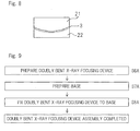
Fig. 9 is a diagram showing process steps of a doubly bent X-ray focusing device assembly manufacturing method according to a seventh embodiment of the present invention; -
Fig. 10 is a diagram showing process steps of a doubly bent X-ray focusing device assembly manufacturing method according to an eighth embodiment of the present invention, or process steps of a doubly bent X-ray spectroscopic device assembly manufacturing method according to an eleventh embodiment of the present invention; and -
Fig. 11 is a diagram showing process steps of a doubly bent X-ray spectroscopic device assembly manufacturing method according to a tenth embodiment of the present invention. - Hereinafter, a doubly bent
X-ray focusing device 1 according to a first embodiment of the present invention will be described. The doubly bentX-ray focusing device 1 of the first embodiment shown inFig. 1 includes: aglass plate 3 which is deformed into a shape having a doubly bent surface by being sandwiched between a doubly curved convex surface of a convex forming die and a doubly curved concave surface, of a concave forming die, that matches the doubly curved convex surface, and being heated to a temperature of 400 °C to 600 °C, for example, 500 °C; and a reflection coating 5 of Au (gold) which is formed on a concave surface 3a of thedeformed glass plate 3 by, for example, vacuum deposition, and is configured to reflect X-rays. Although the doubly bent surface is a toroidal surface (annular side surface) in the doubly bentX-ray focusing device 1 of the present embodiment, the doubly bend surface of the present invention is not limited to the toroidal surface, and may be an ellipsoid of revolution, a logarithmic spiral surface of revolution, or the like. - When the heating temperature to deform the
glass plate 3 is less than 400 °C, theglass plate 3 may sometimes not be formed to have a desired doubly bent surface even if the time for the heating and deformation is increased. On the other hand, when the heating temperature exceeds 600 °C, although the time required for the heating and deformation is reduced, there is a risk that the surface roughness of the convex surface of the convex forming die may be transferred to the concave surface 3a of theglass plate 3. Therefore, the heating temperature to deform theglass plate 3 is preferably 400 °C to 600 °C, and more preferably 450 °C to 550 °C. - The
blank glass plate 3, which has not been deformed, has a surface roughness not more than 0.5 nm in root-mean-square roughness. Theblank glass plate 3 is, for example, a cover glass for microscopic observation or for a display of electronic equipment, and specifically is a rectangle plate made of borosilicate glass and having a long side of 75 mm, a short side of 25 mm, and a thickness of 0.15 mm. The thickness of theblank glass plate 3 is preferably not more than 1 mm because the thinner theblank glass plate 3 is, the more rapidly theblank glass plate 3 is heated and deformed, which facilitates forming. The dimension, shape, and material of theblank glass plate 3 may be other than those mentioned above as long as the surface roughness thereof is not more than 0.5 nm in root-mean-square roughness. - According to the doubly bent
X-ray focusing device 1 of the first embodiment, theblank glass plate 3 is sandwiched between the doubly curved convex surface and the doubly curved concave surface that matches the doubly curved convex surface and is heated to a temperature of 400 °C to 600 °C to be deformed into the shape having the doubly bent surface. As a result, theglass plate 3 is not adversely affected by the surface roughness of the doubly curvedconvex surface 21a of the convex forming die 21 (Fig. 7 ), and has the surface roughness equivalent to that of theglass plate 3 before being heated and deformed. Since the reflection coating 5 is formed on the concave surface 3a of theglass plate 3, excellent focusing performance is achieved. Further, thedeformed glass plate 3 can maintain its shape, that is, has a self-supporting shape. Therefore, only by forming the reflection coating 5 on the concave surface 3a of theglass plate 3, theglass plate 3 can be used as the doubly bentX-ray focusing device 1 that can be handled as it is. - Next, a doubly bent X-ray focusing device assembly according to a second embodiment of the present invention will be described. A doubly bent X-ray focusing device assembly 6 of the second embodiment shown in
Fig. 2 includes the doubly bentX-ray focusing device 1 of the first embodiment, and abase 7 to which the doubly bentX-ray focusing device 1 is fixed. Thebase 7 is a concave stainless-steel base having a doubly curvedconcave surface 7a identical to the doubly curved concave surface of the concave forming die. Aconvex surface 9 of the doubly bent X-ray focusing device 1 (the convex surface of the glass plate 3) is fixed to theconcave surface 7a of thebase 7 by means of an adhesive. - Since the doubly bent
X-ray focusing device 1 has the self-supporting shape, it is sufficient that thebase 7 is a fixture member to which the doubly bentX-ray focusing device 1 can be fixed, and the surface roughness of theconcave surface 7a of thebase 7 may be inferior to the surface roughness of theglass plate 3. Thebase 7 is not limited to theconcave base 7 as shown inFig. 2 , and may be a plate-shapedbase 7 as shown inFig. 3 or a box-shapedbase 7 as shown inFig. 4 . That is, as in a modification shown inFig. 3 , the doubly bent X-ray focusing device assembly 6 may be configured such that a center portion of theconvex surface 9 of the doubly bentX-ray focusing device 1 is fixed to a center portion of the plate-shapedbase 7 by means of an elastic adhesive. Alternatively, as in another modification shown inFig. 4 , the doubly bent X-ray focusing device assembly 6 may be configured such that the four corners of theconvex surface 9 of the doubly bentX-ray focusing device 1 are fixed to the four corners of the box-shapedbase 7 by means of an elastic adhesive. Thebase 7 of the doubly bent X-ray focusing device assembly 6 is not limited to thebases 7 having the shapes shown inFig. 2 to Fig. 4 , and may be a frame-shapedbase 7, or abase 7 having a square hole or a round hole, to which only the periphery of the doubly bentX-ray focusing device 1 is fixed. In these modifications, shape machining of thebase 7 can be easily performed. In addition, even when there is a large temperature change, the difference in thermal expansion coefficient between thebase 7 and theglass plate 3 hardly causes deformation, resulting in a high degree of freedom in selecting the material of thebase 7. - Since the doubly bent X-ray focusing device assembly 6 of the second embodiment includes the doubly bent
X-ray focusing device 1 of the first embodiment, the same effect as that of the doubly bentX-ray focusing device 1 of the first embodiment can be achieved. - Next, a doubly bent X-ray spectroscopic device according to a third embodiment of the present invention will be described. The doubly bent
X-ray spectroscopic device 11 of the third embodiment shown inFig. 1 is different from the doubly bentX-ray focusing device 1 of the first embodiment only in that a synthetic multilayer 15 is formed instead of the reflection coating 5 of the first embodiment, and other components thereof are the same as those of the first embodiment. That is, the synthetic multilayer 15 which monochromates X-rays, for example, a synthetic multilayer for C-Ka line that efficiently monochromates C-Kα line, is formed on the concave surface 3a of theglass plate 3 deformed into a shape having a doubly bent surface. - According to the doubly bent
X-ray spectroscopic device 11 of the third embodiment, like the doubly bentX-ray focusing device 1 of the first embodiment, theglass plate 3 is not adversely affected by the surface roughness of the doubly curvedconvex surface 21a of the convex forming die 21 (Fig. 7 ), and has the surface roughness equivalent to that of theglass plate 3 before being heated and deformed. Since the synthetic multilayer 15 is formed on the concave surface 3a of theglass plate 3, excellent focusing performance and spectroscopic performance are achieved. Further, thedeformed glass plate 3 can maintain its shape, that is, has a self-supporting shape. Therefore, only by forming the synthetic multilayer 15 on the concave surface 3a of theglass plate 3, theglass plate 3 can be used as the doubly bentX-ray focusing device 1 that can be handled as it is. - Next, a doubly bent X-ray
spectroscopic device assembly 16 according to a fourth embodiment of the present invention will be described. The doubly bent X-rayspectroscopic device assembly 16 of the fourth embodiment shown inFig. 2 includes the doubly bentX-ray spectroscopic device 11 of the third embodiment, and abase 7 to which the doubly bentX-ray spectroscopic device 11 is fixed. Thebase 7 is the same as thebase 7 of the doubly bent X-ray focusing device assembly 6 of the second embodiment. - Since the doubly bent X-ray
spectroscopic device assembly 16 of the fourth embodiment includes the doubly bentX-ray spectroscopic device 11 of the third embodiment, the same effect as that of the doubly bentX-ray spectroscopic device 11 of the third embodiment can be achieved. - Next, an X-ray analyzing apparatus according to a fifth embodiment of the present invention will be described. This X-ray analyzing apparatus is an X-ray fluorescence spectrometer, and includes the doubly bent X-ray
spectroscopic device assembly 16 of the fourth embodiment. As shown inFig. 5 , the X-ray analyzing apparatus includes: anX-ray source 51 which irradiates asample 53 withprimary X-rays 52; the doubly bent X-rayspectroscopic device assembly 16 which monochromatesfluorescent X-rays 54 generated from thesample 53; and anX-ray detector 57 which detectsfluorescent X-rays 56 that have been monochromated and focused by the doubly bent X-rayspectroscopic device assembly 16. The X-ray analyzing apparatus performs quantitative analysis and/or qualitative analysis on the basis of detected intensity of the fluorescent X-rays. - Although the X-ray analyzing apparatus according to the fifth embodiment has been described as the X-ray fluorescence spectrometer provided with the doubly bent X-ray
spectroscopic device assembly 16 of the fourth embodiment, the X-ray analyzing apparatus may be provided with at least one of: the doubly bentX-ray focusing device 1 of the first embodiment; the doubly bent X-ray focusing device assembly 6 of the second embodiment; the doubly bentX-ray spectroscopic device 11 of the third embodiment; and the doubly bent X-rayspectroscopic device assembly 16 of the fourth embodiment, or may be an X-ray analyzing apparatus other than X-ray fluorescence spectrometers. - Since the X-ray analyzing apparatus of the fifth embodiment is provided with at least one of: the doubly bent
X-ray focusing device 1 of the first embodiment; the doubly bent X-ray focusing device assembly 6 of the second embodiment; the doubly bentX-ray spectroscopic device 11 of the third embodiment; and the doubly bent X-rayspectroscopic device assembly 16 of the fourth embodiment, the X-ray analyzing apparatus can perform highly accurate measurement while ensuring satisfactory focusing performance and/or spectroscopic performance. - Next, a method for manufacturing the doubly bent
X-ray focusing device 1 according to a sixth embodiment of the present invention will be described. As shown inFig. 6 , this manufacturing method includes: step S1 of preparing theglass plate 3 having a surface roughness not more than 0.5 nm in root-mean-square roughness; step S2 of preparing the convex formingdie 21 having the doubly curvedconvex surface 21a; step S3 of preparing the concave formingdie 22 having the doubly curvedconcave surface 22a which matches the doubly curvedconvex surface 21a; step S4 of deforming theglass plate 3 into the shape having the doubly bent surface by sandwiching theglass plate 3 between the doubly curvedconvex surface 21a of the convex formingdie 21 and the doubly curvedconcave surface 22a of the concave formingdie 22, and heating theglass plate 3 to a temperature of 400 °C to 600 °C; and step S5A (step on the left side inFig. 6 ) of forming the reflection coating 5 which reflects X-rays, on the concave surface of thedeformed glass plate 3. Hereinafter, the manufacturing method will be described in order of the process steps. - In step S1, the
glass plate 3 having the surface roughness not more than 0.5 nm in root-mean-square roughness is prepared. Theblank glass plate 3 is, for example, a cover glass for microscopic observation or for a display of electronic equipment, and specifically, is a rectangle plate made of borosilicate glass and having a long side of 75 mm, a short side of 25 mm, and a thickness of 0.15 mm. The thickness of theblank glass plate 3 is preferably not more than 1 mm because the thinner theblank glass plate 3 is, the more rapidly theblank glass plate 3 is heated and deformed, which facilitates forming. The dimension, shape, and material of theblank glass plate 3 may be other than those mentioned above as long as the surface roughness thereof is not more than 0.5 nm in root-mean-square roughness. - In step S2, the convex forming
die 21 having the desired doubly curvedconvex surface 21a is prepared. The doubly curvedconvex surface 21a of the convex formingdie 21 is a toroidal surface in the manufacturing method of the present embodiment. The convex formingdie 21 is made of stainless steel, and has a mass of 300 g. The doubly curvedconvex surface 21a has, in a plan view, a rectangular shape with a long side of 75 mm and a short side of 25 mm. - In step S3, the concave forming
die 22 having the doubly curvedconcave surface 22a that matches the doubly curvedconvex surface 21a is prepared. The doubly curvedconcave surface 22a is a toroidal surface in the manufacturing method of the present embodiment. The concave formingdie 22 is made of stainless steel. The doubly curvedconcave surface 22a of the concave formingdie 22 has, in a plan view, a rectangular shape with a long side of 75 mm and a short side of 25 mm. The doubly curvedconcave surface 22a that matches the doubly curvedconvex surface 21a means the doubly curvedconcave surface 22a which is shifted from the doubly curvedconvex surface 21a by the thickness of theglass plate 3. The convex formingdie 21 and the concave formingdie 22 are machined dies, and the doubly curvedconvex surface 21a and the doubly curvedconcave surface 22a thereof are not subjected to special surface polishing. Therefore, these dies 21 and 22 are inferior in surface roughness to theblank glass plate 3. - In step S4, as shown in
Fig. 7 , theglass plate 3 is sandwiched between the doubly curvedconvex surface 21a of the convex formingdie 21 and the doubly curvedconcave surface 22a of the concave formingdie 22, and heated at 500 °C for 90 minutes, for example, whereby theglass plate 3 is thermoplastically deformed into a shape having the doubly bent surface only by the self-weight of the convex forming die 21 (Fig. 8 ). If the deformation due to the self-weight of the convex formingdie 21 is not sufficient, a load may be applied from the top of the convex formingdie 21. If theglass plate 3 is heated at a temperature less than 400 °C, theglass plate 3 may sometimes not be formed into a shape having a desired doubly bent surface even if the heating time is increased or the load is increased. On the other hand, if theglass plate 3 is heated at a temperature exceeding 600 °C, although the time required for deformation is reduced, there is a risk that the surface roughness of theconvex surface 21a of the convex formingdie 21 is transferred to the concave surface 3a of theglass plate 3. Therefore, the heating temperature for deforming theglass plate 3 is preferably 400 °C to 600 °C, and more preferably 450 °C to 550 °C. Regarding heating equipment, special equipment for performing the pressurizing deformation at the high temperature is not required, and a simple and inexpensive electric furnace capable of heating theglass plate 3 at 400 °C to 600 °C suffices. - In step S5A of
Fig. 6 , after thedeformed glass plate 3 is slowly cooled, the reflection coating 5 of Au (gold) that reflects X-rays is formed by, for example, vacuum deposition on the concave surface 3a of thedeformed glass plate 3. Through the above-described process steps, the doubly bentX-ray focusing device 1 is manufactured. Thedeformed glass plate 3 can maintain its shape, that is, has a self-supporting shape. Therefore, only by forming the reflection coating 5 on the concave surface 3a of theglass plate 3, theglass plate 3 can be manufactured as the doubly bentX-ray focusing device 1 that can be handled as it is. Although the doubly bent surface is a toroidal surface (annular side surface) in the manufacturing method of the present embodiment, the doubly bend surface of the present invention is not limited to the toroidal surface, and may be an ellipsoid of revolution, a logarithmic spiral surface of revolution, or the like. - According to the manufacturing method of the sixth embodiment, the
glass plate 3 is sandwiched between the doubly curvedconvex surface 21a and the doubly curvedconcave surface 22a that matches the doubly curvedconvex surface 21a, and heated to a temperature of 400 °C to 600 °C to be deformed into a shape having the doubly bent surface. As a result, even when theglass plate 3 is heated and deformed between the convex formingdie 21 and the concave formingdie 22, theglass plate 3 is not adversely affected by the surface roughness of the doubly curvedconvex surface 21a of the convex formingdie 21, and has the surface roughness equivalent to that of theglass plate 3 before being heated and deformed. The reflection coating 5 is formed on the concave surface 3a of theglass plate 3. Therefore, it is possible to easily and inexpensively manufacture the doubly bentX-ray focusing device 1 having excellent focusing performance. - Next, a method for manufacturing the doubly bent X-ray focusing device assembly 6 according to a seventh embodiment of the present invention will be described. As shown in
Fig. 9 , this manufacturing method includes: step S6A of preparing the doubly bentX-ray focusing device 1 manufactured by the manufacturing method of the sixth embodiment; step S7A of preparing thebase 7 to which the doubly bentX-ray focusing device 1 is to be fixed; and step S8A of fixing the doubly bentX-ray focusing device 1 to thebase 7. Hereinafter, the manufacturing method will be described in order of the process steps. - In step S6A, the doubly bent
X-ray focusing device 1 manufactured by the manufacturing method of the sixth embodiment is prepared. - In step S7A, the
base 7 to which the doubly bentX-ray focusing device 1 is to be fixed is prepared. Thesame base 7 as that of the doubly bent X-ray focusing device assembly 6 of the second embodiment, for example, a concave stainless-steel base 7 having the same doubly curvedconcave surface 7a as the doubly curvedconcave surface 22a of the concave formingdie 22, is prepared. - In step S8A, first, an adhesive, for example, epoxy resin, is applied to the entire
concave surface 7a of the base 7 (Fig. 2 ). Next, theconvex surface 9 of the doubly bent X-ray focusing device 1 (Fig. 2 ) is superposed on theconcave surface 7a, of thebase 7, to which the adhesive has been applied. Next, theconvex surface 9 of the doubly bentX-ray focusing device 1 is adhered to theconcave surface 7a of thebase 7 while lightly pressing the doubly bentX-ray focusing device 1 with the doubly curvedconvex surface 21a of the convex formingdie 21. Since the shape of theconvex surface 9 of the doubly bentX-ray focusing device 1, which has the self-supporting shape, matches the shape of theconcave surface 7a of thebase 7, the doubly bentX-ray focusing device 1 is fixed to thebase 7 without being deformed. Through the above-described process steps, the doubly bent X-ray spectroscopic device assembly 6 is manufactured. - According to the manufacturing method of the seventh embodiment, since the doubly bent
X-ray focusing device 1 manufactured by the manufacturing method of the sixth embodiment is fixed to thebase 7, it is possible to easily and inexpensively manufacture the doubly bent X-ray focusing device assembly 6 having excellent focusing performance. - Next, a method for manufacturing a doubly bent X-ray focusing device assembly 6 according to an eighth embodiment of the present invention will be described. As shown in
Fig. 10 , this manufacturing method includes: step S1 of preparing theglass plate 3 having a surface roughness not more than 0.5 nm in root-mean-square roughness; step S2 of preparing the convex formingdie 21 having the doubly curvedconvex surface 21a; step S3 of preparing the concave formingdie 22 having the doubly curvedconcave surface 22a that matches the doubly curvedconvex surface 21a; step S4 deforming theglass plate 3 into a shape having the doubly bent surface by sandwiching theglass plate 3 between the doubly curvedconvex surface 21a of the convex formingdie 21 and the doubly curvedconcave surface 22a of the concave formingdie 22, and heating theglass plate 3 to a temperature of 400 °C to 600 °C; step S5C of preparing thebase 7 to which thedeformed glass plate 3 is to be fix; step S6C of fixing thedeformed glass plate 3 to thebase 7; and step S7C (step on the left side inFig. 10 ) of forming the reflection coating 5 which reflects X-rays, on the concave surface 3a of theglass plate 3 fixed to thebase 7. Hereinafter, the manufacturing method will be described in order of the process steps. - Steps S1 to S4 of the manufacturing method of the eighth embodiment are the same as steps S1 to S4 of the manufacturing method of the sixth embodiment, and the
glass plate 3 is similarly heated and deformed. - In step S5C, the
base 7 to which thedeformed glass plate 3 is to be fixed is prepared. Thesame base 7 as that used in the manufacturing method of the seventh embodiment, for example, a concave stainless-steel base 7 having the same doubly curvedconcave surface 7a as the doubly curvedconcave surface 22a of the concave formingdie 22, is prepared. - In step S6C, first, the convex forming
die 21 and thedeformed glass plate 3 are heated to a melting point of paraffin which is described later, and paraffin is applied to theconvex surface 21a of the convex formingdie 21, and then the concave surface 3a of thedeformed glass plate 3 is superposed on theconvex surface 21a having the paraffin. Then, the convex formingdie 21 and theglass plate 3 are slowly cooled, whereby theglass plate 3 is held on theconvex surface 21 a of the convex formingdie 21 due to the adhesion force of the paraffin. Next, an adhesive, for example, epoxy resin, is applied to the entireconcave surface 7a of thebase 7, and theconvex surface 9 of theglass plate 3 adhered to and held by theconvex surface 21a of the convex formingdie 21 is superposed on and adhered to theconcave surface 7a of thebase 7, thereby fixing theglass plate 3 to thebase 7. - After the
deformed glass plate 3 is fixed, the entire structure, in which the convex formingdie 21, theglass plate 3, and thebase 7 are in the superposed state, is heated to the melting point of paraffin, whereby the convex formingdie 21 is separated from theglass plate 3, and the paraffin remaining on the concave surface 3a of theglass plate 3 is removed. The paraffin used in this embodiment is desired to have a melting point at a low temperature that does not cause degradation of the adhesive, for example, 50 °C to 60 °C. - In step S7C, the reflection coating 5 of Au (gold) that reflects X-rays is formed by, for example, vacuum deposition, on the concave surface 3a of the
deformed glass plate 3 fixed to thebase 7. Through the above-described process steps, the doubly bent X-ray focusing device assembly 6 is manufactured. - According to the manufacturing method of the eighth embodiment, as in the manufacturing method of the sixth embodiment, the
glass plate 3 is sandwiched between the doubly curvedconvex surface 21a and the doubly curvedconcave surface 22a that matches the doubly curvedconvex surface 21a, and heated to a temperature of 400 °C to 600 °C to be deformed into a shape having the doubly bent surface. As a result, theglass plate 3 is not adversely affected by the surface roughness of the doubly curvedconvex surface 21a of the convex formingdie 21, and has the surface roughness equivalent to that of theglass plate 3 before being heated and deformed. Then, the reflection coating 5 is formed on the concave surface 3a of theglass plate 3. Therefore, it is possible to easily and inexpensively manufacture the doubly bent X-ray focusing device assembly 6 having excellent focusing performance. - Next, a method for manufacturing a doubly bent X-ray spectroscopic device according to a ninth embodiment of the present invention will be described. This manufacturing method is different from the manufacturing method of the sixth embodiment only in that, as shown in
Fig. 6 , step S5B (step on the right side inFig. 6 ) of forming the synthetic multilayer 15 that monochromates X-rays, on the concave surface 3a of thedeformed glass plate 3 is included instead of step S5A of forming the reflection coating 5 that reflects X-rays, on the concave surface 3a of thedeformed glass plate 3, and the other steps are the same as those of the sixth embodiment. The synthetic multilayer 15 which monochromates X-rays, for example, a synthetic multilayer 15 for C-Ka line, is formed on the concave surface 3a of thedeformed glass plate 3, thereby to complete the doubly bentX-ray spectroscopic device 11. Thedeformed glass plate 3 can maintain its shape, that is, has a self-supporting shape. Therefore, only by forming the synthetic multilayer 15 on the concave surface 3a of theglass plate 3, theglass plate 3 can be manufactured as the doubly bentX-ray spectroscopic device 11 that can be handled as it is. Although the doubly bent surface is a toroidal surface (annular side surface) in the manufacturing method of the present embodiment, the doubly bend surface of the present invention is not limited to the toroidal surface, and may be an ellipsoid of revolution, a logarithmic spiral surface of revolution, or the like. - According to the manufacturing method of the ninth embodiment, the
glass plate 3 is sandwiched between the doubly curvedconvex surface 21a and the doubly curvedconcave surface 22a that matches the doubly curvedconvex surface 21a, and heated to a temperature of 400 °C to 600 °C to be deformed into a shape having the doubly bent surface. As a result, theglass plate 3 is not adversely affected by the surface roughness of the doubly curvedconvex surface 21a of the convex formingdie 21, and has the surface roughness equivalent to that of theglass plate 3 before being heated and deformed. Then, the synthetic multilayer 15 is formed on the concave surface 3a of theglass plate 3. Therefore, it is possible to easily and inexpensively manufacture the doubly bentX-ray spectroscopic device 11 having excellent focusing performance and spectroscopic performance. - Next, a method for manufacturing the doubly bent X-ray
spectroscopic device assembly 16 according to a tenth embodiment of the present invention will be described. As shown inFig. 11 , this manufacturing method includes: step S6B of preparing the doubly bentX-ray spectroscopic device 11 manufactured by the manufacturing method of the ninth embodiment (Fig. 6 ); step S7B of preparing thebase 7 to which the doubly bentX-ray spectroscopic device 11 is to be fixed; and step S8B of fixing thebase 7 to the doubly bentX-ray spectroscopic device 11. Hereinafter, the manufacturing method will be described in order of the process steps. - In step S6B, the doubly bent
X-ray spectroscopic device 11 manufactured by the manufacturing method of the ninth embodiment (Fig. 6 ) is prepared. - In step S7B, the
base 7 to which the doubly bentX-ray spectroscopic device 11 is to be fixed is prepared. Thesame base 7 as that of the doubly bent X-ray focusing device assembly 6 of the second embodiment, for example, a concave stainless-steel base 7 having the same doubly curvedconcave surface 7a as the doubly curvedconcave surface 22a of the concave formingdie 22, is prepared. - In step S8B, first, an adhesive, for example, epoxy resin, is applied to the entire
concave surface 7a of the base 7 (Fig. 2 ). Next, theconvex surface 9 of the doubly bent X-ray spectroscopic device 11 (Fig. 2 ) is superposed on theconcave surface 7a, of thebase 7, to which the adhesive is applied. Next, theconvex surface 9 of the doubly bentX-ray spectroscopic device 11 is adhered to theconcave surface 7a of thebase 7 while lightly pressing the doubly bentX-ray spectroscopic device 11 with the doubly curvedconvex surface 21a of the convex formingdie 21. Since the shape of theconvex surface 9 of the doubly bentX-ray spectroscopic device 11, which has the self-supporting shape, matches the shape of theconcave surface 7a of thebase 7, the doubly bentX-ray spectroscopic device 11 is fixed to thebase 7 without being deformed. Through the above-described process steps, the doubly bent X-rayspectroscopic device assembly 16 is manufactured. - According to the manufacturing method of the tenth embodiment, since the doubly bent
X-ray spectroscopic device 11 manufactured by the manufacturing method of the ninth embodiment is fixed to thebase 7, it is possible to easily and inexpensively manufacture the doubly bent X-rayspectroscopic device assembly 16 having excellent focusing performance and spectroscopic performance. - Next, a method for manufacturing the doubly bent X-ray
spectroscopic device assembly 16, according to an eleventh embodiment of the present invention will be described. This manufacturing method is different from the manufacturing method of the eighth embodiment only in that, as shown inFig. 10 , step S7D (step on the right side inFig. 10 ) of forming the synthetic multilayer 15 which monochromates X-rays, on the concave surface 3a of the glass plate fixed to thebase 7 is included instead of step S7C of forming the reflection coating 5 which reflects X-rays, on the concave surface 3a of theglass plate 3 fixed to thebase 7, and the other steps are the same as those of the manufacturing method of the eighth embodiment. The synthetic multilayer 15 which monochromates X-rays, for example, a synthetic multilayer for C-Ka line 15, is formed on the concave surface 3a of the glass plate fixed to thebase 7, thereby to complete the doubly bent X-rayspectroscopic device assembly 16. - Steps S1 to S6C of the manufacturing method of the eleventh embodiment are the same as steps S1 to S6C of the manufacturing method of the eighth embodiment, and the heated and
deformed glass plate 3 is similarly fixed to thebase 7. - In step S7D, the synthetic multilayer 15 which monochromates X-rays, for example, a synthetic multilayer 15 for C-Ka line, is formed on the concave surface 3a of the glass plate fixed to the
base 7. Through the above-described process steps, the doubly bent X-rayspectroscopic device assembly 16 is manufactured. - According to the manufacturing method of the eleventh embodiment, as in the manufacturing method of the ninth embodiment, the
glass plate 3 is sandwiched between the doubly curvedconvex surface 21a and the doubly curvedconcave surface 22a that matches the doubly curvedconvex surface 21a, and heated to a temperature of 400 °C to 600 °C to be deformed into a shape having the doubly bent surface. As a result, theglass plate 3 is not adversely affected by the surface roughness of the doubly curvedconvex surface 21a of the convex formingdie 21, and has the surface roughness equivalent to that of theglass plate 3 before being heated and deformed. Then, the synthetic multilayer 15 is formed on the concave surface 3a of theglass plate 3. Therefore, it is possible to easily and inexpensively manufacture the doubly bent X-rayspectroscopic device assembly 16 having excellent focusing performance and spectroscopic performance. - Although the present invention has been fully described in connection with the preferred embodiments thereof with reference to the accompanying drawings, those skilled in the art will readily conceive numerous changes and modifications within the framework of obviousness upon the reading of the specification herein presented of the present invention. Accordingly, such changes and modifications are, unless they depart from the scope of the present invention as delivered from the claims annexed hereto, to be construed as included therein.
-
- 1 ····
- doubly bent X-ray focusing device
- 3 ····
- glass plate
- 3a ····
- concave surface of glass plate
- 5 ····
- reflection coating
- 6 ····
- doubly bent X-ray focusing device assembly
- 7 ····
- base
- 11 ····
- doubly bent X-ray spectroscopic device
- 15 ····
- synthetic multilayer
- 16 ····
- doubly bent X-ray spectroscopic device assembly
- 21 ····
- convex forming die
- 21a ····
- doubly curved convex surface
- 22 ····
- concave forming die
- 22a ····
- doubly curved concave surface
Claims (11)
- A doubly bent X-ray focusing device comprising:a glass plate which is deformed into a shape having a doubly bent surface by being sandwiched between a doubly curved convex surface of a convex forming die and a doubly curved concave surface, of a concave forming die, that matches the doubly curved convex surface, and being heated to a temperature of 400 °C to 600 °C; anda reflection coating configured to reflect X-rays, the reflection coating being formed on a concave surface of the deformed glass plate.
- A doubly bent X-ray focusing device assembly comprising:the doubly bent X-ray focusing device as claimed in claim 1; anda base to which the doubly bent X-ray focusing device is fixed.
- A doubly bent X-ray spectroscopic device comprising:a glass plate which is deformed into a shape having a doubly bent surface by being sandwiched between a doubly curved convex surface of a convex forming die and a doubly curved concave surface, of a concave forming die, that matches the doubly curved convex surface, and being heated to a temperature of 400 °C to 600 °C; anda synthetic multilayer configured to monochromate X-rays, the synthetic multilayer being formed on a concave surface of the deformed glass plate.
- A doubly bent X-ray spectroscopic device assembly comprising:the doubly bent X-ray spectroscopic device as claimed in claim 3; anda base to which the doubly bent X-ray spectroscopic device is fixed.
- An X-ray analyzing apparatus comprising at least one of the doubly bent X-ray focusing device as claimed in claim 1, the doubly bent X-ray focusing device assembly as claimed in claim 2, the doubly bent X-ray spectroscopic device as claimed in claim 3, and the doubly bent X-ray spectroscopic device assembly as claimed in claim 4.
- A method for manufacturing a doubly bent X-ray focusing device, comprising the steps of:preparing a glass plate having a surface roughness not more than 0.5 nm in root-mean-square roughness;preparing a convex forming die having a doubly curved convex surface;preparing a concave forming die having a doubly curved concave surface that matches the doubly curved convex surface;deforming the glass plate into a shape having a doubly bent surface by sandwiching the glass plate between the doubly curved convex surface of the convex forming die and the doubly curved concave surface of the concave forming die, and heating the glass plate to a temperature of 400 °C to 600 °C; andforming a reflection coating that reflects X-rays, on a concave surface of the deformed glass plate.
- A method for manufacturing a doubly bent X-ray focusing device assembly, comprising the steps of:preparing a doubly bent X-ray focusing device manufactured by the manufacturing method as claimed in claim 6;preparing a base to which the doubly bent X-ray focusing device is to be fixed; andfixing the doubly bent X-ray focusing device to the base.
- A method for manufacturing a doubly bent X-ray focusing device assembly, comprising the steps of:preparing a glass plate having a surface roughness not more than 0.5 nm in root-mean-square roughness;preparing a convex forming die having a doubly curved convex surface;preparing a concave forming die having a doubly curved concave surface that matches the doubly curved convex surface;deforming the glass plate into a shape having a doubly bent surface by sandwiching the glass plate between the doubly curved convex surface of the convex forming die and the doubly curved concave surface of the concave forming die, and heating the glass plate to a temperature of 400 °C to 600 °C;preparing a base to which the deformed glass plate is to be fixed;fixing the deformed glass plate to the base; andforming a reflection coating that reflects X-rays, on a concave surface of the glass plate fixed to the base.
- A method for manufacturing a doubly bent X-ray spectroscopic device, comprising the steps of:preparing a glass plate having a surface roughness not more than 0.5 nm in root-mean-square roughness;preparing a convex forming die having a doubly curved convex surface;preparing a concave forming die having a doubly curved concave surface that matches the doubly curved convex surface;deforming the glass plate into a shape having a doubly bent surface by sandwiching the glass plate between the doubly curved convex surface of the convex forming die and the doubly curved concave surface of the concave forming die, and heating the glass plate to a temperature of 400 °C to 600 °C; andforming a synthetic multilayer that monochromates X-rays, on a concave surface of the deformed glass plate.
- A method for manufacturing a doubly bent X-ray spectroscopic device assembly, comprising the steps of:preparing a doubly bent X-ray spectroscopic device manufactured by the manufacturing method as claimed in claim 9;preparing a base to which the doubly bent X-ray spectroscopic device is to be fixed; andfixing the doubly bent X-ray spectroscopic device to the base.
- A method for manufacturing a doubly bent X-ray spectroscopic device assembly, comprising the steps of:preparing a glass plate having a surface roughness not more than 0.5 nm in root-mean-square roughness;preparing a convex forming die having a doubly curved convex surface;preparing a concave forming die having a doubly curved concave surface that matches the doubly curved convex surface;deforming the glass plate into a shape having a doubly bent surface by sandwiching the glass plate between the doubly curved convex surface of the convex forming die and the doubly curved concave surface of the concave forming die, and heating the glass plate to a temperature of 400 °C to 600 °C;preparing a base to which the deformed glass plate is to be fixed;fixing the deformed glass plate to the base; andforming a synthetic multilayer that monochromates X-rays, on a concave surface of the glass plate fixed to the base.
Applications Claiming Priority (2)
| Application Number | Priority Date | Filing Date | Title |
|---|---|---|---|
| JP2015063764A JP6069609B2 (en) | 2015-03-26 | 2015-03-26 | Double-curved X-ray condensing element and its constituent, double-curved X-ray spectroscopic element and method for producing the constituent |
| PCT/JP2016/059266 WO2016152940A1 (en) | 2015-03-26 | 2016-03-23 | Doubly curved x-ray condenser element, doubly curved x-ray spectroscopic element and apparatus equipped with same, and method for manufacturing said elements |
Publications (3)
| Publication Number | Publication Date |
|---|---|
| EP3276630A1 true EP3276630A1 (en) | 2018-01-31 |
| EP3276630A4 EP3276630A4 (en) | 2018-08-01 |
| EP3276630B1 EP3276630B1 (en) | 2019-06-26 |
Family
ID=56977439
Family Applications (1)
| Application Number | Title | Priority Date | Filing Date |
|---|---|---|---|
| EP16768843.1A Active EP3276630B1 (en) | 2015-03-26 | 2016-03-23 | Method for manufacturing doubly bent x-ray focusing device or doubly bent x-ray spectroscopic device |
Country Status (5)
| Country | Link |
|---|---|
| US (1) | US10175185B2 (en) |
| EP (1) | EP3276630B1 (en) |
| JP (1) | JP6069609B2 (en) |
| CN (1) | CN107408417B (en) |
| WO (1) | WO2016152940A1 (en) |
Cited By (1)
| Publication number | Priority date | Publication date | Assignee | Title |
|---|---|---|---|---|
| EP4062428A1 (en) * | 2019-11-22 | 2022-09-28 | Zygo Corporation | Method of reducing roughness and/or defects on an optical surface and mirror formed by same |
Families Citing this family (4)
| Publication number | Priority date | Publication date | Assignee | Title |
|---|---|---|---|---|
| JP6069609B2 (en) * | 2015-03-26 | 2017-02-01 | 株式会社リガク | Double-curved X-ray condensing element and its constituent, double-curved X-ray spectroscopic element and method for producing the constituent |
| US10677744B1 (en) * | 2016-06-03 | 2020-06-09 | U.S. Department Of Energy | Multi-cone x-ray imaging Bragg crystal spectrometer |
| EP3603516A1 (en) * | 2018-08-02 | 2020-02-05 | Siemens Healthcare GmbH | X-ray equipment and method for operating same |
| US12062465B2 (en) | 2022-08-19 | 2024-08-13 | Uchicago Argonne, Llc | System and method for bending crystal wafers for use in high resolution analyzers |
Family Cites Families (89)
| Publication number | Priority date | Publication date | Assignee | Title |
|---|---|---|---|---|
| US4203034A (en) * | 1978-06-01 | 1980-05-13 | University Of Florida Board Of Regents | Diffraction camera for imaging penetrating radiation |
| US4599741A (en) * | 1983-11-04 | 1986-07-08 | USC--Dept. of Materials Science | System for local X-ray excitation by monochromatic X-rays |
| US4807268A (en) * | 1983-11-04 | 1989-02-21 | University Of Southern California | Scanning monochrometer crystal and method of formation |
| JPH0755841B2 (en) * | 1987-02-03 | 1995-06-14 | 旭硝子株式会社 | Bending method of glass plate for laminated glass |
| JPH0833497B2 (en) * | 1987-03-25 | 1996-03-29 | 株式会社島津製作所 | X-ray curved crystal |
| NL8801019A (en) * | 1988-04-20 | 1989-11-16 | Philips Nv | ROENTGEN SPECTROMETER WITH DOUBLE-CURVED CRYSTAL. |
| JP2727745B2 (en) * | 1989-08-24 | 1998-03-18 | 旭硝子株式会社 | Bending method for bent laminated glass and raw glass for laminated glass |
| JPH03131539A (en) * | 1989-10-17 | 1991-06-05 | Asahi Glass Co Ltd | Press mold for bending molding, bending molding of plate glass and device therefor |
| US5127028A (en) * | 1990-08-01 | 1992-06-30 | Wittry David B | Diffractord with doubly curved surface steps |
| US5164975A (en) * | 1991-06-13 | 1992-11-17 | The United States Of America As Represented By The United States Department Of Energy | Multiple wavelength X-ray monochromators |
| JPH08201593A (en) | 1995-01-26 | 1996-08-09 | Nikon Corp | Aspherical reflective optical element |
| JPH08201589A (en) | 1995-01-26 | 1996-08-09 | Nikon Corp | X-ray spectroscopic element |
| JPH10502741A (en) * | 1995-04-26 | 1998-03-10 | フィリップス エレクトロニクス ネムローゼ フェンノートシャップ | Method of manufacturing X-ray optical element for X-ray analyzer |
| JP3705504B2 (en) * | 1995-10-24 | 2005-10-12 | 株式会社アサヒオプティカル | Mold for molding resin lenses for eyeglasses |
| DE69727370T2 (en) * | 1997-06-11 | 2004-12-09 | Istituto Nazionale Di Fisica Nucleare | Multi-stage diffractor made with a constant stage width angle (multi-stage monochromator) |
| US5923720A (en) * | 1997-06-17 | 1999-07-13 | Molecular Metrology, Inc. | Angle dispersive x-ray spectrometer |
| US5892809A (en) * | 1997-09-10 | 1999-04-06 | Wittry; David B. | Simplified system for local excitation by monochromatic x-rays |
| DE19833524B4 (en) * | 1998-07-25 | 2004-09-23 | Bruker Axs Gmbh | X-ray analyzer with gradient multilayer mirror |
| US6285506B1 (en) * | 1999-01-21 | 2001-09-04 | X-Ray Optical Systems, Inc. | Curved optical device and method of fabrication |
| US6498830B2 (en) * | 1999-02-12 | 2002-12-24 | David B. Wittry | Method and apparatus for fabricating curved crystal x-ray optics |
| US6236710B1 (en) * | 1999-02-12 | 2001-05-22 | David B. Wittry | Curved crystal x-ray optical device and method of fabrication |
| US6931097B1 (en) * | 1999-07-22 | 2005-08-16 | Corning Incorporated | Extreme ultraviolet soft x-ray projection lithographic method system and lithographic elements |
| JP2001057328A (en) * | 1999-08-18 | 2001-02-27 | Nikon Corp | Reflection mask, exposure apparatus, and integrated circuit manufacturing method |
| US6381303B1 (en) * | 1999-09-29 | 2002-04-30 | Jordan Valley Applied Radiation Ltd. | X-ray microanalyzer for thin films |
| US6317483B1 (en) * | 1999-11-29 | 2001-11-13 | X-Ray Optical Systems, Inc. | Doubly curved optical device with graded atomic planes |
| US6606371B2 (en) * | 1999-12-20 | 2003-08-12 | Agere Systems Inc. | X-ray system |
| US6697454B1 (en) * | 2000-06-29 | 2004-02-24 | X-Ray Optical Systems, Inc. | X-ray analytical techniques applied to combinatorial library screening |
| US6829327B1 (en) * | 2000-09-22 | 2004-12-07 | X-Ray Optical Systems, Inc. | Total-reflection x-ray fluorescence apparatus and method using a doubly-curved optic |
| RU2339974C2 (en) * | 2001-06-19 | 2008-11-27 | Икс-Рэй Оптикал Системз, Инк. | Wave dispersive x-ray fluorescence system using focusing optics for stimulation and focusing monochromator for collection |
| ATE476088T1 (en) * | 2001-12-04 | 2010-08-15 | X Ray Optical Sys Inc | X-RAY SOURCE WITH IMPROVED BEAM STABILITY AND ITS APPLICATION IN THE ANALYSIS OF FLOWING LIQUIDS |
| US6680996B2 (en) * | 2002-02-19 | 2004-01-20 | Jordan Valley Applied Radiation Ltd. | Dual-wavelength X-ray reflectometry |
| US6816570B2 (en) * | 2002-03-07 | 2004-11-09 | Kla-Tencor Corporation | Multi-technique thin film analysis tool |
| DE20320792U1 (en) * | 2002-06-19 | 2005-05-04 | Xenocs | Optical arrangement and associated device |
| US7104690B2 (en) * | 2002-07-26 | 2006-09-12 | X-Ray Optical Systems, Inc. | Diagnosing system for an x-ray source assembly |
| AU2003256831A1 (en) * | 2002-08-02 | 2004-02-23 | X-Ray Optical Systems, Inc. | An optical device for directing x-rays having a plurality of optical crystals |
| US7763820B1 (en) * | 2003-01-27 | 2010-07-27 | Spectramet, Llc | Sorting pieces of material based on photonic emissions resulting from multiple sources of stimuli |
| US20050011227A1 (en) * | 2003-03-26 | 2005-01-20 | Hoya Corporation | Method of preparation of lens |
| DE102004014954A1 (en) * | 2003-03-27 | 2005-03-10 | Hoya Corp | Method for producing a glass substrate for a mask blank and method for producing a mask blank |
| EP1634065A2 (en) * | 2003-06-02 | 2006-03-15 | X-Ray Optical Systems, Inc. | Method and apparatus for implementing xanes analysis |
| CN1836157B (en) * | 2003-06-17 | 2012-10-03 | X射线光学系统公司 | Removable and X-ray transparent barrier for X-ray analysis of samples under pressure |
| JP2007501503A (en) * | 2003-08-04 | 2007-01-25 | エックス−レイ オプティカル システムズ インコーポレーテッド | X-ray source assembly with improved output stability using tube power regulation and remote calibration |
| US7092843B2 (en) * | 2003-10-21 | 2006-08-15 | X-Ray Optical Systems, Inc. | Apparatus and method for suppressing insignificant variations in measured sample composition data, including data measured from dynamically changing samples using x-ray analysis techniques |
| US7298817B2 (en) * | 2003-12-01 | 2007-11-20 | X-Ray Optical Systems, Inc. | Portable and on-line arsenic analyzer for drinking water |
| JP4710022B2 (en) | 2004-08-27 | 2011-06-29 | 国立大学法人東北大学 | Curvature distribution crystal lens, X-ray apparatus having curvature distribution crystal lens, and method of manufacturing curvature distribution crystal lens |
| US7120228B2 (en) * | 2004-09-21 | 2006-10-10 | Jordan Valley Applied Radiation Ltd. | Combined X-ray reflectometer and diffractometer |
| US7076024B2 (en) * | 2004-12-01 | 2006-07-11 | Jordan Valley Applied Radiation, Ltd. | X-ray apparatus with dual monochromators |
| JP2006308487A (en) * | 2005-04-28 | 2006-11-09 | Canon Inc | Multilayer reflector, method of reusing the multilayer reflector, and exposure apparatus using these multilayer reflectors |
| US7415096B2 (en) * | 2005-07-26 | 2008-08-19 | Jordan Valley Semiconductors Ltd. | Curved X-ray reflector |
| WO2007016484A2 (en) * | 2005-08-01 | 2007-02-08 | The Research Foundation Of State University Of New York | X-ray imaging systems employing point-focusing, curved monochromating optics |
| WO2007019053A1 (en) * | 2005-08-04 | 2007-02-15 | X-Ray Optical Systems, Inc. | Monochromatic x-ray micro beam for trace element mapping |
| US7317784B2 (en) * | 2006-01-19 | 2008-01-08 | Broker Axs, Inc. | Multiple wavelength X-ray source |
| JP4997815B2 (en) * | 2006-04-12 | 2012-08-08 | 旭硝子株式会社 | Method for producing a highly flat and highly smooth glass substrate |
| JP2007285791A (en) * | 2006-04-14 | 2007-11-01 | Rigaku Industrial Co | Concave x-ray spectral element, method for manufacturing the same and x-ray analyzer using the same |
| US7738629B2 (en) * | 2006-11-16 | 2010-06-15 | X-Ray Optical Systems, Inc. | X-ray focusing optic having multiple layers with respective crystal orientations |
| US7440541B2 (en) * | 2006-12-27 | 2008-10-21 | Innov-X-Systems, Inc. | Dual source XRF system |
| JP2008175755A (en) * | 2007-01-22 | 2008-07-31 | Institute X-Ray Technologies Co Ltd | Spectral crystal and method for producing the same |
| EP2109134B1 (en) | 2007-01-25 | 2017-03-01 | Nikon Corporation | Optical element, exposure apparatus employing the optical element, and device manufacturing method |
| EP2162732A1 (en) * | 2007-03-15 | 2010-03-17 | X-ray Optical Systems, INC. | Small spot and high energy resolution xrf system for valence state determination |
| EP2075569B1 (en) * | 2007-12-31 | 2012-02-15 | Xenocs S.A. | X-ray beam device |
| WO2009108628A2 (en) * | 2008-02-25 | 2009-09-03 | X-Ray Optical Systems, Inc. | Sample module with sample stream spaced from window, for x-ray analysis system |
| US7738630B2 (en) * | 2008-03-05 | 2010-06-15 | X-Ray Optical Systems, Inc. | Highly aligned x-ray optic and source assembly for precision x-ray analysis applications |
| CA2753990C (en) * | 2008-03-05 | 2017-11-21 | X-Ray Optical Systems, Inc. | Xrf system having multiple excitation energy bands in highly aligned package |
| US7590220B1 (en) * | 2008-03-10 | 2009-09-15 | General Electric Company | X-ray inspection and detection system and method |
| WO2009126868A1 (en) * | 2008-04-11 | 2009-10-15 | Rigaku Innovative Technologies, Inc. | X-ray generator with polycapillary optic |
| JP5344123B2 (en) * | 2008-07-18 | 2013-11-20 | 独立行政法人 宇宙航空研究開発機構 | X-ray reflector, X-ray reflector, and method for producing X-ray reflector |
| US8058621B2 (en) * | 2009-10-26 | 2011-11-15 | General Electric Company | Elemental composition detection system and method |
| JP5538840B2 (en) * | 2009-11-30 | 2014-07-02 | キヤノン株式会社 | X-ray monochromator, manufacturing method thereof, and X-ray spectrometer |
| DK2606490T3 (en) * | 2010-08-19 | 2018-10-15 | Convergent R N R Ltd | X-ray irradiation of the target volume |
| WO2012050620A1 (en) * | 2010-10-14 | 2012-04-19 | Caldera Pharmaceuticals, Inc. | Method for analysis using x-ray flourescence |
| JP5929903B2 (en) * | 2011-04-01 | 2016-06-08 | 旭硝子株式会社 | Laminated glass and manufacturing method thereof |
| US8557149B2 (en) * | 2011-04-08 | 2013-10-15 | Uchicago Argonne, Llc | System and method for implementing enhanced optics fabrication |
| WO2012177472A2 (en) * | 2011-06-20 | 2012-12-27 | X-Ray Optical Systems, Inc. | Online monitoring of contaminants in crude and heavy fuels, and refinery applications thereof |
| WO2013033572A2 (en) * | 2011-09-01 | 2013-03-07 | Spectramet, Llc | Material sorting technology |
| US9240254B2 (en) * | 2011-09-27 | 2016-01-19 | Revera, Incorporated | System and method for characterizing a film by X-ray photoelectron and low-energy X-ray fluorescence spectroscopy |
| CN103946693B (en) * | 2011-10-06 | 2017-05-03 | X射线光学系统公司 | Mobile transport and shielding apparatus for removable x-ray analyzer |
| WO2013121418A1 (en) * | 2012-02-13 | 2013-08-22 | Convergent R.N.R Ltd | Imaging-guided delivery of x-ray radiation |
| JP6468844B2 (en) * | 2012-02-28 | 2019-02-13 | エックス−レイ オプティカル システムズ インコーポレーテッド | X-ray analyzer in which multiple excitation energy bands are generated using an X-ray tube anode and monochromating optics |
| KR101477469B1 (en) * | 2012-03-30 | 2014-12-29 | 호야 가부시키가이샤 | Substrate for mask blank, substrate with multilayer reflective film, transmissive mask blank, reflective mask blank, transmissive mask, reflective mask, and method for manufacturing semiconductor device |
| JP6206901B2 (en) * | 2012-12-14 | 2017-10-04 | 大学共同利用機関法人 高エネルギー加速器研究機構 | Scattering intensity distribution measuring method and measuring apparatus |
| CN103057122A (en) * | 2012-12-19 | 2013-04-24 | 青岛宙庆工业设计有限公司 | Method for manufacturing double-curved surface acrylic glass |
| US9740091B2 (en) * | 2013-07-22 | 2017-08-22 | Hoya Corporation | Substrate with multilayer reflective film, reflective mask blank for EUV lithography, reflective mask for EUV lithography, and method of manufacturing the same, and method of manufacturing a semiconductor device |
| KR20170120212A (en) * | 2013-09-18 | 2017-10-30 | 호야 가부시키가이샤 | Reflective mask blank and method for manufacturing same, reflective mask, and method for manufacturing semiconductor device |
| KR101877896B1 (en) * | 2013-09-27 | 2018-07-12 | 호야 가부시키가이샤 | Substrate provided with conductive film, substrate provided with multi-layer reflection film, reflective mask blank, reflective mask, and semiconductor device manufacturing method |
| US9551677B2 (en) * | 2014-01-21 | 2017-01-24 | Bruker Jv Israel Ltd. | Angle calibration for grazing-incidence X-ray fluorescence (GIXRF) |
| US9666322B2 (en) * | 2014-02-23 | 2017-05-30 | Bruker Jv Israel Ltd | X-ray source assembly |
| US9823203B2 (en) * | 2014-02-28 | 2017-11-21 | Sigray, Inc. | X-ray surface analysis and measurement apparatus |
| US9594036B2 (en) * | 2014-02-28 | 2017-03-14 | Sigray, Inc. | X-ray surface analysis and measurement apparatus |
| TWI650607B (en) * | 2014-10-21 | 2019-02-11 | 日商Agc股份有限公司 | Substrate with reflective layer for euvl and process for its production, as well as reflective mask blank for euvl and reflective mask for euvl |
| JP6069609B2 (en) * | 2015-03-26 | 2017-02-01 | 株式会社リガク | Double-curved X-ray condensing element and its constituent, double-curved X-ray spectroscopic element and method for producing the constituent |
-
2015
- 2015-03-26 JP JP2015063764A patent/JP6069609B2/en active Active
-
2016
- 2016-03-23 EP EP16768843.1A patent/EP3276630B1/en active Active
- 2016-03-23 WO PCT/JP2016/059266 patent/WO2016152940A1/en not_active Ceased
- 2016-03-23 CN CN201680018150.2A patent/CN107408417B/en active Active
-
2017
- 2017-09-22 US US15/712,799 patent/US10175185B2/en active Active
Cited By (1)
| Publication number | Priority date | Publication date | Assignee | Title |
|---|---|---|---|---|
| EP4062428A1 (en) * | 2019-11-22 | 2022-09-28 | Zygo Corporation | Method of reducing roughness and/or defects on an optical surface and mirror formed by same |
Also Published As
| Publication number | Publication date |
|---|---|
| JP6069609B2 (en) | 2017-02-01 |
| JP2016183888A (en) | 2016-10-20 |
| CN107408417B (en) | 2019-06-21 |
| US20180011035A1 (en) | 2018-01-11 |
| WO2016152940A8 (en) | 2017-08-31 |
| EP3276630B1 (en) | 2019-06-26 |
| EP3276630A4 (en) | 2018-08-01 |
| CN107408417A (en) | 2017-11-28 |
| US10175185B2 (en) | 2019-01-08 |
| WO2016152940A1 (en) | 2016-09-29 |
Similar Documents
| Publication | Publication Date | Title |
|---|---|---|
| US10175185B2 (en) | Methods for manufacturing doubly bent X-ray focusing device, doubly bent X-ray focusing device assembly, doubly bent X-ray spectroscopic device and doubly bent X-ray spectroscopic device assembly | |
| EP2977795B1 (en) | Production method for manufacturing a curved grating | |
| EP2860557B1 (en) | Curved face diffraction grating fabrication method, curved face diffraction grating cast, and curved face diffraction grating employing same | |
| Collon et al. | Silicon pore optics development for ATHENA | |
| US9564252B2 (en) | Method and arrangement for manufacturing a radiation window | |
| Collon et al. | Making the ATHENA optics using silicon pore optics | |
| US20170110621A1 (en) | Method of preparing strain released strip-bent x-ray crystal analyzers | |
| Bavdaz et al. | The ATHENA optics development | |
| TW201101411A (en) | Device for aligning and prefixing a wafer | |
| Salmaso et al. | Building the BEaTriX facility for the ATHENA mirror modules X-ray testing | |
| EP2196998B1 (en) | Curvature distribution crystal lens and x-ray reflectance measuring instrument | |
| Riveros et al. | Progress on the fabrication of high resolution and lightweight monocrystalline silicon x-ray mirrors | |
| JP4710022B2 (en) | Curvature distribution crystal lens, X-ray apparatus having curvature distribution crystal lens, and method of manufacturing curvature distribution crystal lens | |
| Yavaş et al. | Sapphire analyzers for high-resolution X-ray spectroscopy | |
| JPH08201589A (en) | X-ray spectroscopic element | |
| JP2010054433A (en) | Method for holding solid sample for secondary ion mass analysis | |
| Christ et al. | Micro-integrated optical systems and qualification of adhesive integration technologies for cold atomic quantum sensors | |
| JP5320592B2 (en) | Neutron beam monochromator | |
| JP2020003361A (en) | Inspection jig, semiconductor chip inspection method, and semiconductor device manufacturing method | |
| Jedamzik et al. | Dos and don’ts in mounting ZERODUR | |
| WO2020044658A1 (en) | Concave diffraction grating, method for production therefor, and optic device | |
| Kumar | An investigation of eutectic wafer bonding process for micromachined sensors | |
| Nakaniwa et al. | Development of x-ray mirror foils using a hot plastic deformation process | |
| CZ201217A3 (en) | Heat shaped silicon lamellas for precise X-ray optics | |
| US20240062928A1 (en) | System and method for bending crystal wafers for use in high resolution analyzers |
Legal Events
| Date | Code | Title | Description |
|---|---|---|---|
| STAA | Information on the status of an ep patent application or granted ep patent |
Free format text: STATUS: THE INTERNATIONAL PUBLICATION HAS BEEN MADE |
|
| PUAI | Public reference made under article 153(3) epc to a published international application that has entered the european phase |
Free format text: ORIGINAL CODE: 0009012 |
|
| STAA | Information on the status of an ep patent application or granted ep patent |
Free format text: STATUS: REQUEST FOR EXAMINATION WAS MADE |
|
| 17P | Request for examination filed |
Effective date: 20170922 |
|
| AK | Designated contracting states |
Kind code of ref document: A1 Designated state(s): AL AT BE BG CH CY CZ DE DK EE ES FI FR GB GR HR HU IE IS IT LI LT LU LV MC MK MT NL NO PL PT RO RS SE SI SK SM TR |
|
| AX | Request for extension of the european patent |
Extension state: BA ME |
|
| DAV | Request for validation of the european patent (deleted) | ||
| DAX | Request for extension of the european patent (deleted) | ||
| A4 | Supplementary search report drawn up and despatched |
Effective date: 20180703 |
|
| RIC1 | Information provided on ipc code assigned before grant |
Ipc: G21K 1/06 20060101AFI20180627BHEP Ipc: G01N 23/223 20060101ALI20180627BHEP Ipc: G01N 23/207 20180101ALI20180627BHEP |
|
| GRAP | Despatch of communication of intention to grant a patent |
Free format text: ORIGINAL CODE: EPIDOSNIGR1 |
|
| STAA | Information on the status of an ep patent application or granted ep patent |
Free format text: STATUS: GRANT OF PATENT IS INTENDED |
|
| RIC1 | Information provided on ipc code assigned before grant |
Ipc: G01N 23/223 20060101ALI20190129BHEP Ipc: G01N 23/207 20180101ALI20190129BHEP Ipc: G21K 1/06 20060101AFI20190129BHEP |
|
| INTG | Intention to grant announced |
Effective date: 20190219 |
|
| GRAS | Grant fee paid |
Free format text: ORIGINAL CODE: EPIDOSNIGR3 |
|
| GRAA | (expected) grant |
Free format text: ORIGINAL CODE: 0009210 |
|
| STAA | Information on the status of an ep patent application or granted ep patent |
Free format text: STATUS: THE PATENT HAS BEEN GRANTED |
|
| AK | Designated contracting states |
Kind code of ref document: B1 Designated state(s): AL AT BE BG CH CY CZ DE DK EE ES FI FR GB GR HR HU IE IS IT LI LT LU LV MC MK MT NL NO PL PT RO RS SE SI SK SM TR |
|
| REG | Reference to a national code |
Ref country code: GB Ref legal event code: FG4D |
|
| REG | Reference to a national code |
Ref country code: CH Ref legal event code: EP |
|
| REG | Reference to a national code |
Ref country code: AT Ref legal event code: REF Ref document number: 1149253 Country of ref document: AT Kind code of ref document: T Effective date: 20190715 |
|
| REG | Reference to a national code |
Ref country code: DE Ref legal event code: R096 Ref document number: 602016016019 Country of ref document: DE |
|
| REG | Reference to a national code |
Ref country code: IE Ref legal event code: FG4D |
|
| REG | Reference to a national code |
Ref country code: NL Ref legal event code: FP |
|
| PG25 | Lapsed in a contracting state [announced via postgrant information from national office to epo] |
Ref country code: LT Free format text: LAPSE BECAUSE OF FAILURE TO SUBMIT A TRANSLATION OF THE DESCRIPTION OR TO PAY THE FEE WITHIN THE PRESCRIBED TIME-LIMIT Effective date: 20190626 Ref country code: HR Free format text: LAPSE BECAUSE OF FAILURE TO SUBMIT A TRANSLATION OF THE DESCRIPTION OR TO PAY THE FEE WITHIN THE PRESCRIBED TIME-LIMIT Effective date: 20190626 Ref country code: SE Free format text: LAPSE BECAUSE OF FAILURE TO SUBMIT A TRANSLATION OF THE DESCRIPTION OR TO PAY THE FEE WITHIN THE PRESCRIBED TIME-LIMIT Effective date: 20190626 Ref country code: FI Free format text: LAPSE BECAUSE OF FAILURE TO SUBMIT A TRANSLATION OF THE DESCRIPTION OR TO PAY THE FEE WITHIN THE PRESCRIBED TIME-LIMIT Effective date: 20190626 Ref country code: NO Free format text: LAPSE BECAUSE OF FAILURE TO SUBMIT A TRANSLATION OF THE DESCRIPTION OR TO PAY THE FEE WITHIN THE PRESCRIBED TIME-LIMIT Effective date: 20190926 Ref country code: AL Free format text: LAPSE BECAUSE OF FAILURE TO SUBMIT A TRANSLATION OF THE DESCRIPTION OR TO PAY THE FEE WITHIN THE PRESCRIBED TIME-LIMIT Effective date: 20190626 |
|
| REG | Reference to a national code |
Ref country code: LT Ref legal event code: MG4D |
|
| PG25 | Lapsed in a contracting state [announced via postgrant information from national office to epo] |
Ref country code: RS Free format text: LAPSE BECAUSE OF FAILURE TO SUBMIT A TRANSLATION OF THE DESCRIPTION OR TO PAY THE FEE WITHIN THE PRESCRIBED TIME-LIMIT Effective date: 20190626 Ref country code: LV Free format text: LAPSE BECAUSE OF FAILURE TO SUBMIT A TRANSLATION OF THE DESCRIPTION OR TO PAY THE FEE WITHIN THE PRESCRIBED TIME-LIMIT Effective date: 20190626 Ref country code: GR Free format text: LAPSE BECAUSE OF FAILURE TO SUBMIT A TRANSLATION OF THE DESCRIPTION OR TO PAY THE FEE WITHIN THE PRESCRIBED TIME-LIMIT Effective date: 20190927 Ref country code: BG Free format text: LAPSE BECAUSE OF FAILURE TO SUBMIT A TRANSLATION OF THE DESCRIPTION OR TO PAY THE FEE WITHIN THE PRESCRIBED TIME-LIMIT Effective date: 20190926 |
|
| REG | Reference to a national code |
Ref country code: AT Ref legal event code: MK05 Ref document number: 1149253 Country of ref document: AT Kind code of ref document: T Effective date: 20190626 |
|
| PG25 | Lapsed in a contracting state [announced via postgrant information from national office to epo] |
Ref country code: PT Free format text: LAPSE BECAUSE OF FAILURE TO SUBMIT A TRANSLATION OF THE DESCRIPTION OR TO PAY THE FEE WITHIN THE PRESCRIBED TIME-LIMIT Effective date: 20191028 Ref country code: CZ Free format text: LAPSE BECAUSE OF FAILURE TO SUBMIT A TRANSLATION OF THE DESCRIPTION OR TO PAY THE FEE WITHIN THE PRESCRIBED TIME-LIMIT Effective date: 20190626 Ref country code: RO Free format text: LAPSE BECAUSE OF FAILURE TO SUBMIT A TRANSLATION OF THE DESCRIPTION OR TO PAY THE FEE WITHIN THE PRESCRIBED TIME-LIMIT Effective date: 20190626 Ref country code: SK Free format text: LAPSE BECAUSE OF FAILURE TO SUBMIT A TRANSLATION OF THE DESCRIPTION OR TO PAY THE FEE WITHIN THE PRESCRIBED TIME-LIMIT Effective date: 20190626 Ref country code: AT Free format text: LAPSE BECAUSE OF FAILURE TO SUBMIT A TRANSLATION OF THE DESCRIPTION OR TO PAY THE FEE WITHIN THE PRESCRIBED TIME-LIMIT Effective date: 20190626 Ref country code: EE Free format text: LAPSE BECAUSE OF FAILURE TO SUBMIT A TRANSLATION OF THE DESCRIPTION OR TO PAY THE FEE WITHIN THE PRESCRIBED TIME-LIMIT Effective date: 20190626 |
|
| PG25 | Lapsed in a contracting state [announced via postgrant information from national office to epo] |
Ref country code: ES Free format text: LAPSE BECAUSE OF FAILURE TO SUBMIT A TRANSLATION OF THE DESCRIPTION OR TO PAY THE FEE WITHIN THE PRESCRIBED TIME-LIMIT Effective date: 20190626 Ref country code: IT Free format text: LAPSE BECAUSE OF FAILURE TO SUBMIT A TRANSLATION OF THE DESCRIPTION OR TO PAY THE FEE WITHIN THE PRESCRIBED TIME-LIMIT Effective date: 20190626 Ref country code: IS Free format text: LAPSE BECAUSE OF FAILURE TO SUBMIT A TRANSLATION OF THE DESCRIPTION OR TO PAY THE FEE WITHIN THE PRESCRIBED TIME-LIMIT Effective date: 20191026 Ref country code: SM Free format text: LAPSE BECAUSE OF FAILURE TO SUBMIT A TRANSLATION OF THE DESCRIPTION OR TO PAY THE FEE WITHIN THE PRESCRIBED TIME-LIMIT Effective date: 20190626 |
|
| PG25 | Lapsed in a contracting state [announced via postgrant information from national office to epo] |
Ref country code: TR Free format text: LAPSE BECAUSE OF FAILURE TO SUBMIT A TRANSLATION OF THE DESCRIPTION OR TO PAY THE FEE WITHIN THE PRESCRIBED TIME-LIMIT Effective date: 20190626 |
|
| PG25 | Lapsed in a contracting state [announced via postgrant information from national office to epo] |
Ref country code: PL Free format text: LAPSE BECAUSE OF FAILURE TO SUBMIT A TRANSLATION OF THE DESCRIPTION OR TO PAY THE FEE WITHIN THE PRESCRIBED TIME-LIMIT Effective date: 20190626 Ref country code: DK Free format text: LAPSE BECAUSE OF FAILURE TO SUBMIT A TRANSLATION OF THE DESCRIPTION OR TO PAY THE FEE WITHIN THE PRESCRIBED TIME-LIMIT Effective date: 20190626 |
|
| PG25 | Lapsed in a contracting state [announced via postgrant information from national office to epo] |
Ref country code: IS Free format text: LAPSE BECAUSE OF FAILURE TO SUBMIT A TRANSLATION OF THE DESCRIPTION OR TO PAY THE FEE WITHIN THE PRESCRIBED TIME-LIMIT Effective date: 20200320 |
|
| REG | Reference to a national code |
Ref country code: DE Ref legal event code: R097 Ref document number: 602016016019 Country of ref document: DE |
|
| PLBE | No opposition filed within time limit |
Free format text: ORIGINAL CODE: 0009261 |
|
| STAA | Information on the status of an ep patent application or granted ep patent |
Free format text: STATUS: NO OPPOSITION FILED WITHIN TIME LIMIT |
|
| PG2D | Information on lapse in contracting state deleted |
Ref country code: IS |
|
| 26N | No opposition filed |
Effective date: 20200603 |
|
| PG25 | Lapsed in a contracting state [announced via postgrant information from national office to epo] |
Ref country code: SI Free format text: LAPSE BECAUSE OF FAILURE TO SUBMIT A TRANSLATION OF THE DESCRIPTION OR TO PAY THE FEE WITHIN THE PRESCRIBED TIME-LIMIT Effective date: 20190626 |
|
| PG25 | Lapsed in a contracting state [announced via postgrant information from national office to epo] |
Ref country code: MC Free format text: LAPSE BECAUSE OF FAILURE TO SUBMIT A TRANSLATION OF THE DESCRIPTION OR TO PAY THE FEE WITHIN THE PRESCRIBED TIME-LIMIT Effective date: 20190626 |
|
| REG | Reference to a national code |
Ref country code: CH Ref legal event code: PL |
|
| REG | Reference to a national code |
Ref country code: BE Ref legal event code: MM Effective date: 20200331 |
|
| PG25 | Lapsed in a contracting state [announced via postgrant information from national office to epo] |
Ref country code: LU Free format text: LAPSE BECAUSE OF NON-PAYMENT OF DUE FEES Effective date: 20200323 |
|
| PG25 | Lapsed in a contracting state [announced via postgrant information from national office to epo] |
Ref country code: CH Free format text: LAPSE BECAUSE OF NON-PAYMENT OF DUE FEES Effective date: 20200331 Ref country code: IE Free format text: LAPSE BECAUSE OF NON-PAYMENT OF DUE FEES Effective date: 20200323 Ref country code: FR Free format text: LAPSE BECAUSE OF NON-PAYMENT OF DUE FEES Effective date: 20200331 Ref country code: LI Free format text: LAPSE BECAUSE OF NON-PAYMENT OF DUE FEES Effective date: 20200331 |
|
| PG25 | Lapsed in a contracting state [announced via postgrant information from national office to epo] |
Ref country code: BE Free format text: LAPSE BECAUSE OF NON-PAYMENT OF DUE FEES Effective date: 20200331 |
|
| GBPC | Gb: european patent ceased through non-payment of renewal fee |
Effective date: 20200323 |
|
| PG25 | Lapsed in a contracting state [announced via postgrant information from national office to epo] |
Ref country code: GB Free format text: LAPSE BECAUSE OF NON-PAYMENT OF DUE FEES Effective date: 20200323 |
|
| PG25 | Lapsed in a contracting state [announced via postgrant information from national office to epo] |
Ref country code: MT Free format text: LAPSE BECAUSE OF FAILURE TO SUBMIT A TRANSLATION OF THE DESCRIPTION OR TO PAY THE FEE WITHIN THE PRESCRIBED TIME-LIMIT Effective date: 20190626 Ref country code: CY Free format text: LAPSE BECAUSE OF FAILURE TO SUBMIT A TRANSLATION OF THE DESCRIPTION OR TO PAY THE FEE WITHIN THE PRESCRIBED TIME-LIMIT Effective date: 20190626 |
|
| PG25 | Lapsed in a contracting state [announced via postgrant information from national office to epo] |
Ref country code: MK Free format text: LAPSE BECAUSE OF FAILURE TO SUBMIT A TRANSLATION OF THE DESCRIPTION OR TO PAY THE FEE WITHIN THE PRESCRIBED TIME-LIMIT Effective date: 20190626 |
|
| PGFP | Annual fee paid to national office [announced via postgrant information from national office to epo] |
Ref country code: NL Payment date: 20260213 Year of fee payment: 11 |
|
| PGFP | Annual fee paid to national office [announced via postgrant information from national office to epo] |
Ref country code: DE Payment date: 20260128 Year of fee payment: 11 |