EP3276386A1 - Optische kopplung von eingebetteten glasfasern - Google Patents
Optische kopplung von eingebetteten glasfasern Download PDFInfo
- Publication number
- EP3276386A1 EP3276386A1 EP16180924.9A EP16180924A EP3276386A1 EP 3276386 A1 EP3276386 A1 EP 3276386A1 EP 16180924 A EP16180924 A EP 16180924A EP 3276386 A1 EP3276386 A1 EP 3276386A1
- Authority
- EP
- European Patent Office
- Prior art keywords
- optical
- optical fiber
- fiber
- embedded
- external
- Prior art date
- Legal status (The legal status is an assumption and is not a legal conclusion. Google has not performed a legal analysis and makes no representation as to the accuracy of the status listed.)
- Pending
Links
Images


Classifications
-
- G—PHYSICS
- G02—OPTICS
- G02B—OPTICAL ELEMENTS, SYSTEMS OR APPARATUS
- G02B6/00—Light guides; Structural details of arrangements comprising light guides and other optical elements, e.g. couplings
- G02B6/24—Coupling light guides
- G02B6/26—Optical coupling means
- G02B6/262—Optical details of coupling light into, or out of, or between fibre ends, e.g. special fibre end shapes or associated optical elements
-
- G—PHYSICS
- G02—OPTICS
- G02B—OPTICAL ELEMENTS, SYSTEMS OR APPARATUS
- G02B6/00—Light guides; Structural details of arrangements comprising light guides and other optical elements, e.g. couplings
- G02B6/10—Light guides; Structural details of arrangements comprising light guides and other optical elements, e.g. couplings of the optical waveguide type
- G02B6/12—Light guides; Structural details of arrangements comprising light guides and other optical elements, e.g. couplings of the optical waveguide type of the integrated circuit kind
- G02B6/13—Integrated optical circuits characterised by the manufacturing method
- G02B6/138—Integrated optical circuits characterised by the manufacturing method by using polymerisation
-
- G—PHYSICS
- G02—OPTICS
- G02B—OPTICAL ELEMENTS, SYSTEMS OR APPARATUS
- G02B6/00—Light guides; Structural details of arrangements comprising light guides and other optical elements, e.g. couplings
- G02B6/24—Coupling light guides
- G02B6/36—Mechanical coupling means
- G02B6/3628—Mechanical coupling means for mounting fibres to supporting carriers
- G02B6/3632—Mechanical coupling means for mounting fibres to supporting carriers characterised by the cross-sectional shape of the mechanical coupling means
- G02B6/3644—Mechanical coupling means for mounting fibres to supporting carriers characterised by the cross-sectional shape of the mechanical coupling means the coupling means being through-holes or wall apertures
-
- G—PHYSICS
- G02—OPTICS
- G02B—OPTICAL ELEMENTS, SYSTEMS OR APPARATUS
- G02B6/00—Light guides; Structural details of arrangements comprising light guides and other optical elements, e.g. couplings
- G02B6/24—Coupling light guides
- G02B6/36—Mechanical coupling means
- G02B6/38—Mechanical coupling means having fibre to fibre mating means
- G02B6/3807—Dismountable connectors, i.e. comprising plugs
- G02B6/381—Dismountable connectors, i.e. comprising plugs of the ferrule type, e.g. fibre ends embedded in ferrules, connecting a pair of fibres
- G02B6/3825—Dismountable connectors, i.e. comprising plugs of the ferrule type, e.g. fibre ends embedded in ferrules, connecting a pair of fibres with an intermediate part, e.g. adapter, receptacle, linking two plugs
-
- G—PHYSICS
- G02—OPTICS
- G02B—OPTICAL ELEMENTS, SYSTEMS OR APPARATUS
- G02B6/00—Light guides; Structural details of arrangements comprising light guides and other optical elements, e.g. couplings
- G02B6/24—Coupling light guides
- G02B6/36—Mechanical coupling means
- G02B6/3616—Holders, macro size fixtures for mechanically holding or positioning fibres, e.g. on an optical bench
-
- G—PHYSICS
- G02—OPTICS
- G02B—OPTICAL ELEMENTS, SYSTEMS OR APPARATUS
- G02B6/00—Light guides; Structural details of arrangements comprising light guides and other optical elements, e.g. couplings
- G02B6/24—Coupling light guides
- G02B6/36—Mechanical coupling means
- G02B6/38—Mechanical coupling means having fibre to fibre mating means
- G02B6/3807—Dismountable connectors, i.e. comprising plugs
- G02B6/381—Dismountable connectors, i.e. comprising plugs of the ferrule type, e.g. fibre ends embedded in ferrules, connecting a pair of fibres
- G02B6/3818—Dismountable connectors, i.e. comprising plugs of the ferrule type, e.g. fibre ends embedded in ferrules, connecting a pair of fibres of a low-reflection-loss type
- G02B6/382—Dismountable connectors, i.e. comprising plugs of the ferrule type, e.g. fibre ends embedded in ferrules, connecting a pair of fibres of a low-reflection-loss type with index-matching medium between light guides
Definitions
- the invention relates to the field of light guide devices. More specifically it relates to the field of interconnections of embedded optical fibers.
- Embedding of fiber optic sensors in materials is a known technology to measure in-situ material deformations.
- one of the main problems is usually to find suitable methods for connecting this embedded fiber with an external fiber.
- several ingress/egress techniques exist mainly based on feed through designs and external coupling, the resilience and strength of the coupling is not guaranteed.
- Optical fiber sensors are normally spliced to a pigtail which connects the sensor with its read-out device. This typically needs some length of fiber, such as a few centimetres, starting from the edge of the composite.
- Composite structures are usually fabricated by moulding, in which cases embedding of optical fibers in composite laminates can be performed during fabrication. After fabrication and prior to use, trimming of the structure edges is often necessary. By trimming the edges, all fiber ingress points will be lost, and as a consequence splicing is very difficult or impossible to carry out when the fiber is broken at the edge of the composite.
- a possible solution is avoiding cutting the fiber.
- a connection may be provided in the waveguide embedded in the material during the fabrication.
- the solution is cumbersome.
- the embedded fiber in such system has restricted orientations and positions, and the production mould and established manufacture route needs to be adapted.
- the fiber is protected using Teflon or other types of tubing or Kapton foil. Sometimes the outcome of the fiber is protected with silicone. It is hardly possible to trim edges or remove mould burrs off the material.
- Other options include removing partially composite material, for example several layers on the side along the fiber, revealing a portion thereof, and then connecting the fiber in the revealed side. This is a cumbersome method, it requires a separate protective block for the fiber and the removed parts of the composite, and prior knowledge of the position of the fiber is necessary, or at least a reliable method to find it, which is not trivial in many cases.
- Document DE102012020920A1 describes a method for connection of optical fibers used as optical sensors in e.g. automotive industry, involving embedding fiber in glass-fiber reinforced plastic, and turning front sides of ends of fibers towards each other. A portion of the embedding material, surrounding the fiber, is typically removed before an optical fiber ferrule and sleeve is used to align the embedded fiber with the external fiber. Finally, an arc is used to connect them. This method may damage the optical fiber and its cleave angle may introduce losses. These losses add up to the losses from splicing fibers, which take place especially in the usual case in which both fibers are different (e.g. one may be optimized for FBG sensing, while the other for signal transmission).
- the present invention relates to an optical system comprising a first optical fiber embedded in an embedding material, the first optical fiber comprising side walls extending in a longitudinal direction in contact with the embedding material, a second, external, optical fiber, and a self written waveguide in optical contact with the first and second optical fibers thus forming an optical connection between the first optical fiber and the second optical fiber, wherein only a cross section perpendicular to the side walls of the first optical fiber is outside the embedding material, in contact with the self written waveguide. It is an advantage of embodiments of the present invention that easy manufacture and reparability are obtained. It is an advantage of embodiments of the present invention that accurate optical interconnection between two optical fibers is obtained.
- the embedding material may be a composite. It is an advantage of embodiments of the present invention that a composite with embedded optical fiber can be obtained in a standard manufacturing process, without the need to introduce a connection during the process.
- the system furthermore may comprise a strain relieve element decoupling the stress acting on the second optical fiber from the optical connection. It is an advantage of embodiments of the present invention that no strain is induced on the self written waveguide. It is an advantage of embodiments that a good attachment between the embedded optical fiber and an external optical fiber is provided, and that a smooth optical transition between the two optical fibers is established, whereby coupling between different optical fibers can be obtained by providing a gradual conversion of the mode field diameter.
- the optical system may further comprise a ferrule, a block, a connector, a base plate or a combination of these attached to the self-written waveguide. It is an advantage of embodiments of the present invention that a reinforcement of the external optical fiber, such as a reader fiber pigtail, is obtained. The connection may also easily and reliably be manufactured.
- the ferrule may be adapted to cooperate with an external ferrule of a removable optical fiber, in order to provide optical contact between the second optical fiber and the removable fiber. It is an advantage of embodiments of the present invention that the connection may be detachable, allowing for example different readers to be connected to an embedded fiber sensor.
- Both ferrules may have angled termination.
- angled connectors are used to avoid unwanted reflection.
- the connection is not detachable, the use of angled fibers/Ferrules is less important since the fiber facet is embedded in the SWW material which has an index close to that of the fibers.
- the connection is detachable, the detachable interface part needs to have an angled fiber facet to avoid reflection. This is the main advantage of using an angled surface.
- the optical fibers may be single mode optical fibers. It is an advantage of embodiments of the present invention that the connection may be aligned in an easy way.
- the first optical fiber may be an optical fiber sensor for detecting deformations in the embedding material
- the second optical fiber may be an optical fiber adapted for information transmission. It is an advantage of embodiments of the present invention that damages and stress can be detected in a composite, such as a structural composite, during use, without the need of complex fabrication processes for embedding the sensor with connection in the composite.
- the present invention also relates to a method for optically coupling an external optical fiber with an optical fiber embedded in an embedding material, thereby obtaining an optical system according to the present invention, the method comprising exposing an end-face of the embedded optical fiber without needing to expose the side walls of the optical fiber out of the embedding material, aligning an end-face of the external optical fiber with the exposed end-face of the embedded optical fiber, and providing an optical intermediate waveguide material between the end-faces of the two optical fibers, thereby obtaining a self-written waveguide between the embedded optical fiber and the external optical fiber.
- trimming is not required, obtaining a reliable and stable connection. It is a further advantage that two different waveguides may connect with minimum loss.
- Aligning the exposed end-faces of the waveguides may comprise transmitting a signal through the external waveguide and measuring the difference in reflectivity between the end-face of the embedded optical fiber and the composite material, thus revealing the location of the embedded optical fiber. It is an advantage of embodiments of the present invention that good fine alignment can be obtained, ensuring maximum transmission between the optical fibers. The latter can be obtained without needing additional components and in reflection. The embedded optical fiber does not need to be connected.
- Obtaining a self-written waveguide may comprise the steps of dispensing an optical polymer between the end-faces of the two optical fibers, forming the core of the self-written waveguide, and forming the cladding of the self-written waveguide. It is an advantage of embodiments of the present invention that good alignment of the core fibers can be obtained. It is a further advantage that a smooth, gradual match between mode field diameters (MFDs) of the embedded and the external optical fibers can be obtained.
- MFDs mode field diameters
- Forming the core of the self-written waveguide may comprise transmitting an UV signal through the optical fibers and forming the cladding may comprise applying flood UV exposure to the optical polymer. It is an advantage of embodiments of the present invention that different degrees of curing can be reached in the SWW, allowing flexibility of optical index difference between the core and the cladding of the SWW, thus allowing tailoring the transmission between the external and embedded optical fibers.
- Alignment may be performed with support of a base plate. It is an advantage of embodiments of the present invention that mechanical and thermal stability can be obtained, for example during manufacture, by use of a carbon and/or composite base plate.
- end-face of an optical fiber reference is made to the cross section of the optical fiber, usually perpendicular to the side walls, from which the radiation leaves the optical fiber.
- the side walls comprise the cladding
- the end-faces of the fiber are the sections at the opposite extremes of the fiber, revealing the fiber core. If the end-face is oblique to the side walls, it receives the name of "cleaved end-face" due to the usual method of obtaining it.
- the present invention relates to an optical system providing a connection between two optical fibers, one of which is embedded in material such as a composite material, the other being an external optical fiber, by an intermediate waveguide providing adhesion and optical connection with low losses between the embedded optical fiber and the external optical fiber.
- the embedded optical fiber is completely buried within the material, except for its end-face, which is in contact with the exterior via an aperture or window in the material.
- the surface of composite material may contain the surface of the end-face, giving a smooth transition between the two different surfaces with no bumps or depressions.
- the intermediate waveguide is made in contact with the end-face of the embedded optical fiber, it may also be in direct contact with the portion of the composite surrounding the optical fiber, and it is in contact with the external optical fiber.
- the material serving as intermediate waveguide is an optical material, e.g. a self-written waveguide (SWW), e.g. with adhesive properties (optical adhesive, for example "NOA68"). Because the embedded optical fiber and the external optical fiber may be different, ideally the optical material should roughly "average” properties of both optical fibers (average optical index, average mode field diameter (MFD)). It was found that the SWW can act as a mode field diameter converter between two different optical fibers and therefore result in a lower loss than a simple butt-coupling connection of those 2 fibers.
- SWW self-written waveguide
- connection between a sensor (e.g. "DTG-sensor”) fiber and an external standard telecom (e.g. "SMF-28”) fiber is explained by comparison with splicing. Because the optical properties of both fibers are different (e.g. the core diameter is different), the mode field diameter of the light travelling in both fibers is different which will result in an additional loss when simply splicing those fibers.
- the idea described here uses an intermediate (self-written) waveguide structure that acts as a mode field converter, thereby minimizing the theoretical achievable losses of the DTG-SMF28 connection.
- the external optical fiber is an optical fiber that is not embedded in the embedding material.
- connection of the present invention is highly reproducible, inexpensive, and simple. It does not require removal of composite walls or material which may reduce the durability of the composite.
- the optical system furthermore comprises a mechanical connection between the composite material, directly or indirectly, and the external optical fiber, e.g. a pigtail of that optical fiber.
- the mechanical connection thereby is established in such a way that there is no direct force acting on the optical connection, e.g. on the self written waveguide, thus decoupling mechanical and optical aspects.
- FIG. 1 shows a schematic cross-section of a simple connection according to an embodiment of the present invention.
- a first optical fiber 100 comprising a fiber core 101 is embedded in an embedding material 102.
- the optical fiber 100 is completely embedded in the material at the zone of the connection except for the end-face 103 of the optical fiber, the entirety of its side walls 104 being in contact with the embedding material 102.
- the end-face 103 of the embedded optical fiber 100 is shown in line with the surface 105 of the material 102.
- this is not essential in the present invention, and the optical fiber 100 may not be completely embedded in its whole length, just in a portion proximal to the end-face.
- the extreme of the optical fiber 100 opposite to the end-face 103 may be outside the material, or some areas of the material may reveal the optical fiber.
- a portion of the side walls 104 extending from the end-face 103 may be also revealed, slightly.
- a second, external, optical fiber 110 is provided.
- An intermediate optical material 120 is fabricated in contact with the external optical fiber 110 and it is also provided at the end-face 103 of the embedded optical fiber 100.
- the intermediate optical material 120 is provided as a self-written waveguide 121.
- the intermediate material 120 covers the totality of the end-face 103, but it may also extend over part of the surface 105 of the material 102.
- the core 111 of the external optical fiber 110 and the core 101 of the embedded optical fiber 100 are preferably optically aligned.
- the invention is not limited to said configurations.
- the SWW 121 covers at least the core of the embedded optical fiber but may not cover the complete end-face of the embedded optical fiber.
- the embedding material may be a composite such as a composite sheet, and the embedded optical fiber may be an optical fiber buried within and extending underneath the surface.
- the composite sheet has certain thickness, thus the sheet comprises at least a side surface (e.g. a border surface along the composite thickness), and the end-face of the optical fiber may be comprised in the side surface of the sheet.
- the optical fiber may comprise a sensor, such as a deformation sensor comprising a fiber Bragg grating (FBG), a sensor for detecting internal damage in the composite, etc.
- FBG fiber Bragg grating
- the external optical fiber may be an optical fiber optimized for telecommunications. In embodiments of the present invention, it may be an optical fiber for providing a connection to a sensor reader (e.g. directly connected to a reader, or adapted in the system as a pigtailing fiber (or pigtail) for providing such connection to a sensor fiber, for example).
- optical fibers for transmission to a reader and optical fibers for sensing may have different characteristics and standards. For example, the numerical aperture and cut-off wavelength of both optical fibers may be different.
- the diameter of the core 101 of the embedded optical fiber 100 may differ from the diameter of the core 111 of the external optical fiber 110.
- the mode field diameter (MFD) of the embedded optical fiber 100 may be different from the MFD of the external optical fiber 110.
- Embodiments of the present invention allow a smooth match between the different optical fibers, irrespective of their MFDs, through the intermediate optical material 120, which may be a self-written waveguide SWW.
- the SWW may offer MFD conversion, gradually adapting the MDC when the optical mode signal travels through the connection, improving the performance in comparison with other techniques such as fusion splice. For example, it may provide a gradual conversion, e.g. a linear conversion, or a step-wise conversion.
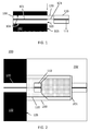
- FIG. 2 shows a schematic of a realistic implementation of the concept shown in FIG. 1 , including the optical connection as well as a mechanical housing 202.
- the intermediate optical material 120 such as a SWW 121, extends over part of the surface 105 of a material 102 (e.g. a composite) comprising an embedded optical fiber 100, improving mechanical resilience and stability of the connection. Resilience may be further improved by the addition of an adhesive layer 200, which may have the same or different composition as the intermediate material 120 (e.g. the adhesive may comprise material suitable for a SWW 121, but it may also be other type of adhesive).
- a ferrule 201 for example a ceramic ferrule, is in contact with the external optical fiber, which may be an optical fiber "pigtail" 110. The ferrule 201 is mainly used for handling during connectorization. The ferrule 201 also provides mechanical resilience and support to the fiber pigtail 110, which may or may not stick out of the ferrule.
- a reinforcement housing 202 may be provided.
- the optical connection can be provided between single-mode optical fibers, although the present invention may also provide an optical connection between multi-mode or multi-core fibers.
- the present invention relates to a method for obtaining an optical connection according to embodiments of the first aspect of the present invention.
- the method may comprise providing SWW 121 in an egress and ingress method of optical transmission in an embedded optical fiber such as a fiber sensor.
- the method is suitable for optically coupling an external optical fiber (such as a fiber pigtail of a sensor reader) with an optical fiber embedded in an embedding material (such as the optical fiber of a deformation sensor in an embedding composite), and it may advantageously reduce coupling losses.
- FIG. 3 shows a flowchart with the main steps (full lines) and optional steps (dashed lines) of the present method.
- the step of providing 301 an optical fiber in a material may comprise embedding an optical fiber (e.g. a fiber sensor, such as a FBG sensor) in a composite material by placing the optical fiber in a mould, without any connectors, and curing the composite.
- the rest of the process comprises providing a connection (connectorizing) in the material.
- Other sub-steps such as trimming, removing burrs, and other treatments may be comprised in this step. It is an advantage that the standard fabrication process of the material or composite does not need to be changed in order to provide connectors.
- a step of exposing 302 the end-face of the embedded optical fiber is provided.
- a cut can be made in the composite after curing, for example using a diamond blade, exposing the end-face of the embedded fiber.
- a diamond blade has the advantages that little or no strain or damage is introduced in the optical fiber or the especially delicate fiber core.
- Other methods may be used, such as slicing the material with a microtome, removing material by grinding and/or polishing, etc.
- the end-face may be revealed by grinding away material from the surface that will contain the connections (e.g.
- the step of providing 303 an external optical fiber comprises providing an optical fiber with at least one end-face for receiving optical signals therein. For example, at least one end-face should be properly obtained with few or no defects.
- the method may further comprise the optional step of providing 313 a reinforcing ferrule, which may be attached to the pigtail, which optionally may stick out of the ferrule, for facilitating further connection with an external sensor, reader, fiber, etc.
- the ferrule may be a micro-ferrule.
- a number of fibers may be used whereby instead of a ferrule e.g. a block with precise v-grooves can be used.
- the step of aligning 304 an end-face of the external optical fiber with the exposed end-face of the embedded optical fiber, so there is optical connection between the optical fibers, is provided.
- the core 101, 111 of the optical fibers 100, 110 should be aligned with respect to each other, as shown in FIG. 1 . Due to the small size of the optical fibers (usually less than 200 microns), this process is not trivial. Although the use of a camera may be an option, the embedded optical fiber may be difficult to see due to low contrast. This also has the disadvantage that an additional camera would be required.
- the aligning 304 may comprise setting the external optical fiber at an appropriate distance (e.g.
- the present invention shows two exemplary methods of alignment, in transmission and in reflection.
- a signal is introduced through the opposite side of the embedded optical fiber and the signal is searched on the surface.
- the embedded optical fiber is connectorized on the side opposite to the end-face 103 to be attached to the SWW, it can be connected to a laser source.
- the external optical fiber is then connected to a detector, and the surface of the composite is scanned. When the external optical fiber detects an intensity maximum, the external optical fiber and the embedded optical fiber are aligned.
- the signal is introduced in the external optical fiber, illuminating the relevant portion of surface of the material in which the end-face of the embedded optical fiber is expected.
- the reflectivity of the composite and the end-face of the optical fiber are typically different, and can be known.
- the external optical fiber scans the surface, and once the maximum reflection typical from the embedded optical fiber is detected, the external and the embedded optical fibers are aligned.
- the present invention may use one or another method, or may use a combination of both.
- a method in reflection may be used for aligning a first end of an embedded optical fiber, connection between external and embedded optical fibers may be done and subsequently be used to align a second end of the embedded optical fiber.
- the alignment may comprise performing 314 coarse alignment and/or performing 324 fine alignment.
- Fine or micro alignment can be used for an optical fiber sensor (e.g. a fiber comprising a FBG), by scanning over the edge of the embedding material, as before. From the external optical fiber, a signal (e.g. broadband light) is launched, matching what is required for reading out the FBG sensor. The external optical fiber is now scanned over the edge of the composite material comprising the embedded optical fiber with FBG sensor, so that the highest reflection peak is obtained when both optical fibers are aligned.
- This technique is mainly suitable when both optical fibers are already slightly aligned, for example via a coarse alignment, and only require final fine scanning to exactly align both optical fibers.
- the optional, coarse, alignment e.g. over millimeter range
- a faster technique in which the external optical fiber scans the surface and analyzes the difference in reflectivity of glass (embedded fiber) and composite material, which displays a "signature" from which the location of the embedded optical fiber can be revealed.
- This "signature” may be a smoother and more uniform reflection profile when mapping the area of the optical fiber than when mapping in the composite surface.
- a peak of reflection intensity may also be obtained at the edge between the composite and the optical fiber, and if the optical fiber comprises a FBG, a reflection peak in the center, allowing fine alignment.
- the large step size of a coarse alignment makes this option advantageously faster.
- the method comprises the steps of providing 305 optical material in the gap between both optical fibers and obtaining 306 an intermediate waveguide by forming a SWW.
- the gap may be approximately 50 microns.
- a small blob of material of 50 or 60 microns of diameter may be provided, the present invention not being limited thereto.
- the optical material should cover the end-faces of the optical fiber, and may extend over the sides of the external optical fiber, and/or over any reinforcement structure (e.g. a ferrule). The material may extend over the wall of the composite.
- the optical fibers may be brought to contact for a reference measurement, then separated at the distance required for the intermediate optical material, and then obtaining 306 an intermediate waveguide.
- Writing the waveguide may comprise introducing an UV signal in the optical material via the external optical fiber such as a 405 nm laser signal, thereby forming the core of the SWW.
- Writing the waveguide may further comprise UV flooding the surface of the optical material, thereby forming the cladding of the SWW.
- This curing step may be tailored, so the optical index in the core is known and different from the index in the cladding. The difference of optical indices influences the MFD.
- the SWW may be tailored for a certain gradient of MFD and transition. Typically, maximum transmission between the external optical fiber and the embedded optical fiber is desired, but other applications may aim at lower transmissions.
- An additional layer of optical material, or adhesive may be provided to cover the intermediate waveguide and provide mechanical stability.
- Mechanical effects such as variations of volume due to heating during the UV curing, are prejudicial for the very sensitive alignment between the optical fibers, but these effects may be counteracted by the use of a base plate, such as a carbon or composite removable base plate, which provides mechanical and thermal stability.
- Providing an additional layer of optical material or a base plate may be done sequentially or simultaneously with the step of aligning 304 the optical fibers. For example, SWW may be obtained while monitoring in reflection the alignment (e.g. by observing the grating spectra). Monitoring also provides information regarding the curing process.
- the external optical fiber e.g. the pigtail fiber
- the external optical fiber may comprise a ferrule, which provides resilience to the connection during manufacture and use, even in an ultrathin foil embedding.
- structural reinforcement such as a housing, strain reliefs, etc. may be provided 316.
- Embodiments of the present invention advantageously ensure an easy-to-use and reliable mechanical connection.
- This can for example be obtained by use of a fiber ferrule, by fixing the fiber in or on a block, a connector, a base plate or a combination of these. It ensures a more stable mechanical connection with the composite (owing to the larger diameter compared to the fiber itself).
- a standard, ceramic or otherwise, fiber ferrule may be used, which provides compatibility with standard connectors. This step may be performed even before obtaining the SWW, for example it may be done at the point of providing 303 the external optical fiber, so when the SWW-based optical connection is made, the pigtail optical fiber is already mounted in the ferrule.
- the external pigtailing fiber or external optical fiber is permanently attached to the ferrule, using a proper mechanical part as reinforcement.
- This mechanical reinforcement part may be applied after providing 305 optical material between the optical fibers or after obtaining 306 the SWW (e.g. by sliding it over the already attached ferrule), or may be mounted at the same time than the SWW is fabricated 306. In case of the latter, the complete assembly (ferrule and reinforcement) is then used during alignment and mounted simultaneously.
- the external pigtailing optical fiber/ferrule assembly 401 is mounted in a sleeve or holder 402 during the connectorizing process in such a way that the holder 402 can still be removed and, for example, replaced by a different connector (e.g. standard FC/APC).
- the holder 402 is replaced by the final connector housing and everything is mounted as a complete assembly. After the process, the removable ferrule 403 can be disconnected and replaced by the desired fiber patch cord.
- the method may comprise further steps, such as removing the detachable ferrule 403 not fixed to the SWW and the temporary connector 402 (if such devices were used during the previous steps), providing a connection housing, which may include providing a holder for the SWW material, providing a strain relief fixation for reducing bending and strain on the pigtail optical fiber and/orthe external optical fiber, and/or adding a cable fixation structure and a dust cover.
- FIG. 5 shows a finalized connection comprising a housing 501, which may have been provided after removal of the holder 402 and the removable ferrule 403.
- An advantage of embodiments of the present invention is the possibility of coupling two different types of optical fibers with very low losses.
- a monitoring source 601 and one or two detectors 602, 603 may be used.
- a superluminescent LED (SLED) may be a suitable monitoring source 601, and the detectors, a photodiode 602 and an Optical Spectrum Analyzer (OSA) 603, can used in transmission, but other detectors and sources may be used.
- SLED and OSA can be substituted by other detectors if the alignment is performed in reflection.
- a fiber interrogator may be used.
- the setup is controlled by a processing unit 604 such as a computer, which may also control triggering of the source 605, for example a 405 nm laser source, allowing precise and automatic data acquisition which facilitates process optimization.
- the pigtailing fiber 606 is provided, which may be the same material as the embedded fiber or a different material and may be the same or different type of fiber. Between the pigtail 606 and the composite embedded fiber 608, optical material 607 is provided and alignment can be done.
- the 405 nm source may be introduced in the fiber upon alignment, and a cladding may be formed on the optical material 607 via UV flood 609. Further optical components shown are a splitter 610 and a circulator 611.
- the fiber tips may at this point slightly stick out of the ferrule. This facilitates initial tests, but is not essential and other configurations may be used, such as a standard polished fiber-ferrule assembly. If no fiber sticks out, the connection may present improved mechanical resilience, e.g. similar to commercial assemblies in which the fiber is not sticking out.
- the insertion loss is measured continuously during the course of the experiment. This serves as a direct feedback for the success of the connection process and gives insight on the SWW formation process. In such a way, parameter optimization becomes also easier.
- the signal in reflection could be employed as a figure of merit, in case the embedded fiber has no connector.
- an embedded commercial fiber sensor can be coupled to a commercial telecommunication fiber.
- the embedded fiber may be a DTG 1550-125, optimized for 1550 nm wavelength window, and with a diameter of 125 microns, a core index of 1.459 and a refractive index contrast (RIC) of 0.015 (RIC represents the difference of optical indices between the core and the cladding).
- the telecommunication fiber may be e.g. an SMF-28 fiber with a core index of 1.473 and RIC of 0.005.
- RIC represents the difference between core and cladding optical indices
- different values may be obtained for different curing types and curing times. If the RIC in the SWW is similar to that in the SMF-28 fiber (bottom power distribution plot in FIG 7 ), the MFD of a mode propagating from the SMF-28 fiber side presents only a small variation. When the RIC is increased, the maximum value of the power (in the center of the waveguide/fiber) is increased. The total power is conserved; thus the MFD is reduced (higher mode peak power).
- the minimum achievable loss for this specific simulation case is about 0.42dB. It is possible that a more optimized RIC profile of the SWW may still reduce this value. For example, a gradual change in RIC will likely reduce the loss, but this is more difficult to obtain in practice.
- the loss between an SMF-28 fiber - (uncured NOA68) - DTG fiber at nearly 0 micron separation was simulated to be about 0.9dB, which is similar to the expected splice losses.
- connection breaks the embedding fiber may be lost, impeding any chance of reparation, or if reparation is possible, very complex and even destructive methods may be necessary.
- the present method offers the advantage that, in case of damage or loss of the connection, it can be easily repaired by repeating alignment and providing the intermediate WG. At most, a slight polishing of the surface may be needed.
Landscapes
- Physics & Mathematics (AREA)
- General Physics & Mathematics (AREA)
- Optics & Photonics (AREA)
- Engineering & Computer Science (AREA)
- Microelectronics & Electronic Packaging (AREA)
- Optical Couplings Of Light Guides (AREA)
- Mechanical Coupling Of Light Guides (AREA)
Priority Applications (2)
| Application Number | Priority Date | Filing Date | Title |
|---|---|---|---|
| EP16180924.9A EP3276386A1 (de) | 2016-07-25 | 2016-07-25 | Optische kopplung von eingebetteten glasfasern |
| US15/656,737 US10466419B2 (en) | 2016-07-25 | 2017-07-21 | Optical coupling of embedded optical fibers |
Applications Claiming Priority (1)
| Application Number | Priority Date | Filing Date | Title |
|---|---|---|---|
| EP16180924.9A EP3276386A1 (de) | 2016-07-25 | 2016-07-25 | Optische kopplung von eingebetteten glasfasern |
Publications (1)
| Publication Number | Publication Date |
|---|---|
| EP3276386A1 true EP3276386A1 (de) | 2018-01-31 |
Family
ID=56511427
Family Applications (1)
| Application Number | Title | Priority Date | Filing Date |
|---|---|---|---|
| EP16180924.9A Pending EP3276386A1 (de) | 2016-07-25 | 2016-07-25 | Optische kopplung von eingebetteten glasfasern |
Country Status (2)
| Country | Link |
|---|---|
| US (1) | US10466419B2 (de) |
| EP (1) | EP3276386A1 (de) |
Families Citing this family (6)
| Publication number | Priority date | Publication date | Assignee | Title |
|---|---|---|---|---|
| JP2019174610A (ja) * | 2018-03-28 | 2019-10-10 | 技術研究組合光電子融合基盤技術研究所 | 光コネクタ、光コネクタの製造方法、及び光コネクタを備える光電気混載デバイス |
| WO2020209364A1 (ja) | 2019-04-11 | 2020-10-15 | アダマンド並木精密宝石株式会社 | 光コネクタと、光コネクタの製造方法 |
| JP7511208B2 (ja) * | 2019-04-11 | 2024-07-05 | Orbray株式会社 | 光コネクタと、光コネクタの製造方法 |
| WO2023238322A1 (ja) * | 2022-06-09 | 2023-12-14 | 日本電信電話株式会社 | 光素子、光集積素子および光素子の製造方法 |
| JP2024074480A (ja) * | 2022-11-21 | 2024-05-31 | 国立大学法人宇都宮大学 | 自己形成光導波路の製造方法 |
| GR1010660B (el) * | 2023-07-31 | 2024-03-21 | Componous Ιδιωτικη Κεφαλαιουχικη Εταιρεια, | Οπτικη συζευξη σε ελευθερο χωρο ενσωματωμενων οπτικων ινων |
Citations (7)
| Publication number | Priority date | Publication date | Assignee | Title |
|---|---|---|---|---|
| US20020172470A1 (en) * | 2001-05-15 | 2002-11-21 | The Boeing Company | Embeddable fiber optic connector and associated method |
| EP1503231A1 (de) * | 2002-04-26 | 2005-02-02 | Ibiden Co., Ltd. | Optische übertragungsstruktur, optischer leiter, verfahren zur herstellung eines optischen wellenleiters und optischer verbindungskoppler |
| JP2006317533A (ja) * | 2005-05-10 | 2006-11-24 | Bridgestone Corp | 光接続部材およびその製造方法 |
| JP2010032584A (ja) * | 2008-07-25 | 2010-02-12 | Toyota Central R&D Labs Inc | 光導波路及び光モジュール、並びにそれらの製造方法 |
| US20100104243A1 (en) * | 2006-02-17 | 2010-04-29 | Telescent Inc. | Protective fiber optic union adapters |
| DE102012020920A1 (de) | 2011-10-26 | 2013-05-02 | Fiberware Generalunternehmen für Nachrichtentechnik GmbH | Verfahren zur Verbindung zweier optischer Fasern, von denen eine Faser in einem Kunststoff eingebettet ist, und entsprechende Verbindungsvorrichtung |
| WO2015126561A1 (en) * | 2014-02-21 | 2015-08-27 | Dow Corning Corporation | Method of preparing an optical connector and optical devices comprising the optical connector prepared thereby |
Family Cites Families (17)
| Publication number | Priority date | Publication date | Assignee | Title |
|---|---|---|---|---|
| US4717253A (en) * | 1985-11-22 | 1988-01-05 | Massachusetts Institute Of Technology | Optical strain gauge |
| WO2005062095A2 (en) * | 2003-12-22 | 2005-07-07 | Bae Systems Plc | Embedded fibre optic connector and method of its interfacing with a surface connector |
| WO2005062094A1 (en) * | 2003-12-22 | 2005-07-07 | Bae Systems Plc | Optical connector arrangement |
| US20050271336A1 (en) * | 2004-05-17 | 2005-12-08 | Photintech Inc. | Material composition for the stable coupling of optical components |
| US7251398B2 (en) * | 2004-08-26 | 2007-07-31 | Interuniversitair Microelektronica Centrum (Imec) | Method for providing an optical interface and devices according to such methods |
| JP4496319B2 (ja) * | 2005-09-06 | 2010-07-07 | 国立大学法人静岡大学 | 光導波路及びその製造方法 |
| JP4945107B2 (ja) * | 2005-09-15 | 2012-06-06 | ゲットナー・ファンデーション・エルエルシー | 光源装置及びその製造方法、表示装置及びその製造方法、並びに表示装置の駆動方法 |
| JP4946315B2 (ja) * | 2006-09-28 | 2012-06-06 | 株式会社豊田中央研究所 | 自己形成光導波路の製造方法 |
| JP4970364B2 (ja) * | 2008-06-27 | 2012-07-04 | 豊田合成株式会社 | 光分岐結合器及びその製造方法 |
| US8622625B2 (en) * | 2009-05-29 | 2014-01-07 | Corning Incorporated | Fiber end face void closing method, a connectorized optical fiber assembly, and method of forming same |
| CN105264415A (zh) * | 2013-04-02 | 2016-01-20 | 泰科电子瑞侃有限公司 | 用于光纤连接器的自写入波导及相关方法 |
| US9817191B2 (en) * | 2013-06-14 | 2017-11-14 | Chiral Photonics, Inc. | Multichannel optical coupler array |
| JP5656099B1 (ja) * | 2013-06-28 | 2015-01-21 | Toto株式会社 | 光レセプタクル、フェルールおよびプラグフェルール |
| US9939590B2 (en) * | 2013-10-22 | 2018-04-10 | CommScope Connectivity Spain, S.L. | Self-cleaning fiber optic connection system |
| US10073226B2 (en) * | 2014-05-15 | 2018-09-11 | Imec Vzw | Method for coupling an optical fiber to an optical or optoelectronic component |
| US20160062039A1 (en) * | 2014-09-02 | 2016-03-03 | Tyco Electronics Corporation | Mode size converters and optical assemblies |
| US20160072585A1 (en) * | 2014-09-08 | 2016-03-10 | Helios Lightworks, LLC | Method Of Creating An Optical Link Among Devices |
-
2016
- 2016-07-25 EP EP16180924.9A patent/EP3276386A1/de active Pending
-
2017
- 2017-07-21 US US15/656,737 patent/US10466419B2/en active Active
Patent Citations (7)
| Publication number | Priority date | Publication date | Assignee | Title |
|---|---|---|---|---|
| US20020172470A1 (en) * | 2001-05-15 | 2002-11-21 | The Boeing Company | Embeddable fiber optic connector and associated method |
| EP1503231A1 (de) * | 2002-04-26 | 2005-02-02 | Ibiden Co., Ltd. | Optische übertragungsstruktur, optischer leiter, verfahren zur herstellung eines optischen wellenleiters und optischer verbindungskoppler |
| JP2006317533A (ja) * | 2005-05-10 | 2006-11-24 | Bridgestone Corp | 光接続部材およびその製造方法 |
| US20100104243A1 (en) * | 2006-02-17 | 2010-04-29 | Telescent Inc. | Protective fiber optic union adapters |
| JP2010032584A (ja) * | 2008-07-25 | 2010-02-12 | Toyota Central R&D Labs Inc | 光導波路及び光モジュール、並びにそれらの製造方法 |
| DE102012020920A1 (de) | 2011-10-26 | 2013-05-02 | Fiberware Generalunternehmen für Nachrichtentechnik GmbH | Verfahren zur Verbindung zweier optischer Fasern, von denen eine Faser in einem Kunststoff eingebettet ist, und entsprechende Verbindungsvorrichtung |
| WO2015126561A1 (en) * | 2014-02-21 | 2015-08-27 | Dow Corning Corporation | Method of preparing an optical connector and optical devices comprising the optical connector prepared thereby |
Also Published As
| Publication number | Publication date |
|---|---|
| US20180024295A1 (en) | 2018-01-25 |
| US10466419B2 (en) | 2019-11-05 |
Similar Documents
| Publication | Publication Date | Title |
|---|---|---|
| US10466419B2 (en) | Optical coupling of embedded optical fibers | |
| US6690867B2 (en) | Optical interconnect assemblies and methods therefor | |
| US9568685B2 (en) | Connectorization techniques for polarization-maintaining and multicore optical fiber cables | |
| US9316796B2 (en) | Fiber pigtail with integrated lid | |
| US9864150B2 (en) | Optical interconnection component | |
| JP2009122451A (ja) | 光学接続構造 | |
| EP2402805A1 (de) | Optische Presshülse | |
| US7577330B2 (en) | Connectorized nano-engineered optical fibers and methods of forming same | |
| JPH1172649A (ja) | 光繊維手動整列装置及び方法 | |
| US20110142402A1 (en) | Optical fiber and method of manufacturing the same, end part processing method of optical fiber and optical fiber with ferrule | |
| US20050259919A1 (en) | Optical connector arrangement | |
| US9557492B2 (en) | Fibre stub device and method using butt coupling for receptacled photonic devices | |
| US20240085644A1 (en) | Method For Orienting And Terminating Polarization-Maintaining (PM) Optical Fiber And Forming A PM Optical Fiber Assembly | |
| US20050259909A1 (en) | Fibre optic connectors and methods | |
| US4629316A (en) | Attenuation across optical fiber splice | |
| US11550103B2 (en) | Optical connection component | |
| KR20000036055A (ko) | 광학 소자를 제조하는 방법 및 이 방법에 따라 제조된 광학 소자 | |
| US20050286834A1 (en) | Waveguide assembly and connector | |
| KR20030004656A (ko) | 광센서를 이용한 평면 도파로형 광회로 칩의 접합 장치 | |
| Missinne et al. | Low-loss connection of embedded optical fiber sensors using a self-written waveguide | |
| US20230400637A1 (en) | Method for constructing light transmission system, and on-site construction set | |
| US20230280533A1 (en) | Re-Spliceable Splice-On Connector and Method of Making Same | |
| US20240255705A1 (en) | Method for manufacturing optical fiber bundle, optical fiber bundle, optical connection structure, and determination method | |
| WO2024166205A1 (ja) | 光ファイバカプラ、光ファイバカプラの製造方法、及び光合分波方法 | |
| CN115508953A (zh) | 光连接构造体 |
Legal Events
| Date | Code | Title | Description |
|---|---|---|---|
| PUAI | Public reference made under article 153(3) epc to a published international application that has entered the european phase |
Free format text: ORIGINAL CODE: 0009012 |
|
| STAA | Information on the status of an ep patent application or granted ep patent |
Free format text: STATUS: THE APPLICATION HAS BEEN PUBLISHED |
|
| AK | Designated contracting states |
Kind code of ref document: A1 Designated state(s): AL AT BE BG CH CY CZ DE DK EE ES FI FR GB GR HR HU IE IS IT LI LT LU LV MC MK MT NL NO PL PT RO RS SE SI SK SM TR |
|
| AX | Request for extension of the european patent |
Extension state: BA ME |
|
| STAA | Information on the status of an ep patent application or granted ep patent |
Free format text: STATUS: REQUEST FOR EXAMINATION WAS MADE |
|
| 17P | Request for examination filed |
Effective date: 20180713 |
|
| RBV | Designated contracting states (corrected) |
Designated state(s): AL AT BE BG CH CY CZ DE DK EE ES FI FR GB GR HR HU IE IS IT LI LT LU LV MC MK MT NL NO PL PT RO RS SE SI SK SM TR |
|
| STAA | Information on the status of an ep patent application or granted ep patent |
Free format text: STATUS: EXAMINATION IS IN PROGRESS |
|
| 17Q | First examination report despatched |
Effective date: 20200513 |
|
| STAA | Information on the status of an ep patent application or granted ep patent |
Free format text: STATUS: EXAMINATION IS IN PROGRESS |