EP3274529B1 - Motor vehicle lock - Google Patents
Motor vehicle lock Download PDFInfo
- Publication number
- EP3274529B1 EP3274529B1 EP16734552.9A EP16734552A EP3274529B1 EP 3274529 B1 EP3274529 B1 EP 3274529B1 EP 16734552 A EP16734552 A EP 16734552A EP 3274529 B1 EP3274529 B1 EP 3274529B1
- Authority
- EP
- European Patent Office
- Prior art keywords
- motor vehicle
- door
- lock
- opening
- open position
- Prior art date
- Legal status (The legal status is an assumption and is not a legal conclusion. Google has not performed a legal analysis and makes no representation as to the accuracy of the status listed.)
- Active
Links
- 230000007246 mechanism Effects 0.000 claims description 24
- 230000005291 magnetic effect Effects 0.000 claims description 5
- 230000000903 blocking effect Effects 0.000 claims 1
- 230000006378 damage Effects 0.000 description 4
- 238000007789 sealing Methods 0.000 description 4
- 230000001747 exhibiting effect Effects 0.000 description 2
- 238000009434 installation Methods 0.000 description 2
- 230000003993 interaction Effects 0.000 description 2
- 239000012858 resilient material Substances 0.000 description 2
- 229910000639 Spring steel Inorganic materials 0.000 description 1
- 230000015572 biosynthetic process Effects 0.000 description 1
- 238000005352 clarification Methods 0.000 description 1
- 238000010276 construction Methods 0.000 description 1
- 230000005294 ferromagnetic effect Effects 0.000 description 1
- -1 for example Substances 0.000 description 1
- 239000000463 material Substances 0.000 description 1
- 238000000034 method Methods 0.000 description 1
- 230000008569 process Effects 0.000 description 1
- 238000007493 shaping process Methods 0.000 description 1
Images
Classifications
-
- E—FIXED CONSTRUCTIONS
- E05—LOCKS; KEYS; WINDOW OR DOOR FITTINGS; SAFES
- E05B—LOCKS; ACCESSORIES THEREFOR; HANDCUFFS
- E05B81/00—Power-actuated vehicle locks
- E05B81/12—Power-actuated vehicle locks characterised by the function or purpose of the powered actuators
- E05B81/14—Power-actuated vehicle locks characterised by the function or purpose of the powered actuators operating on bolt detents, e.g. for unlatching the bolt
-
- E—FIXED CONSTRUCTIONS
- E05—LOCKS; KEYS; WINDOW OR DOOR FITTINGS; SAFES
- E05B—LOCKS; ACCESSORIES THEREFOR; HANDCUFFS
- E05B81/00—Power-actuated vehicle locks
- E05B81/12—Power-actuated vehicle locks characterised by the function or purpose of the powered actuators
- E05B81/13—Power-actuated vehicle locks characterised by the function or purpose of the powered actuators a single actuator for driving a lock and additional vehicle components, e.g. window wipers or window lifters
-
- E—FIXED CONSTRUCTIONS
- E05—LOCKS; KEYS; WINDOW OR DOOR FITTINGS; SAFES
- E05B—LOCKS; ACCESSORIES THEREFOR; HANDCUFFS
- E05B81/00—Power-actuated vehicle locks
- E05B81/12—Power-actuated vehicle locks characterised by the function or purpose of the powered actuators
- E05B81/20—Power-actuated vehicle locks characterised by the function or purpose of the powered actuators for assisting final closing or for initiating opening
-
- B—PERFORMING OPERATIONS; TRANSPORTING
- B60—VEHICLES IN GENERAL
- B60J—WINDOWS, WINDSCREENS, NON-FIXED ROOFS, DOORS, OR SIMILAR DEVICES FOR VEHICLES; REMOVABLE EXTERNAL PROTECTIVE COVERINGS SPECIALLY ADAPTED FOR VEHICLES
- B60J1/00—Windows; Windscreens; Accessories therefor
- B60J1/08—Windows; Windscreens; Accessories therefor arranged at vehicle sides
-
- B—PERFORMING OPERATIONS; TRANSPORTING
- B60—VEHICLES IN GENERAL
- B60J—WINDOWS, WINDSCREENS, NON-FIXED ROOFS, DOORS, OR SIMILAR DEVICES FOR VEHICLES; REMOVABLE EXTERNAL PROTECTIVE COVERINGS SPECIALLY ADAPTED FOR VEHICLES
- B60J5/00—Doors
- B60J5/04—Doors arranged at the vehicle sides
- B60J5/047—Doors arranged at the vehicle sides characterised by the opening or closing movement
-
- E—FIXED CONSTRUCTIONS
- E05—LOCKS; KEYS; WINDOW OR DOOR FITTINGS; SAFES
- E05C—BOLTS OR FASTENING DEVICES FOR WINGS, SPECIALLY FOR DOORS OR WINDOWS
- E05C17/00—Devices for holding wings open; Devices for limiting opening of wings or for holding wings open by a movable member extending between frame and wing; Braking devices, stops or buffers, combined therewith
- E05C17/02—Devices for holding wings open; Devices for limiting opening of wings or for holding wings open by a movable member extending between frame and wing; Braking devices, stops or buffers, combined therewith by mechanical means
- E05C17/04—Devices for holding wings open; Devices for limiting opening of wings or for holding wings open by a movable member extending between frame and wing; Braking devices, stops or buffers, combined therewith by mechanical means with a movable bar or equivalent member extending between frame and wing
- E05C17/045—Hinges for the movable bar
-
- E—FIXED CONSTRUCTIONS
- E05—LOCKS; KEYS; WINDOW OR DOOR FITTINGS; SAFES
- E05C—BOLTS OR FASTENING DEVICES FOR WINGS, SPECIALLY FOR DOORS OR WINDOWS
- E05C17/00—Devices for holding wings open; Devices for limiting opening of wings or for holding wings open by a movable member extending between frame and wing; Braking devices, stops or buffers, combined therewith
- E05C17/02—Devices for holding wings open; Devices for limiting opening of wings or for holding wings open by a movable member extending between frame and wing; Braking devices, stops or buffers, combined therewith by mechanical means
- E05C17/04—Devices for holding wings open; Devices for limiting opening of wings or for holding wings open by a movable member extending between frame and wing; Braking devices, stops or buffers, combined therewith by mechanical means with a movable bar or equivalent member extending between frame and wing
- E05C17/047—Portable bars or the like, i.e. completely removable
-
- E—FIXED CONSTRUCTIONS
- E05—LOCKS; KEYS; WINDOW OR DOOR FITTINGS; SAFES
- E05C—BOLTS OR FASTENING DEVICES FOR WINGS, SPECIALLY FOR DOORS OR WINDOWS
- E05C17/00—Devices for holding wings open; Devices for limiting opening of wings or for holding wings open by a movable member extending between frame and wing; Braking devices, stops or buffers, combined therewith
- E05C17/02—Devices for holding wings open; Devices for limiting opening of wings or for holding wings open by a movable member extending between frame and wing; Braking devices, stops or buffers, combined therewith by mechanical means
- E05C17/04—Devices for holding wings open; Devices for limiting opening of wings or for holding wings open by a movable member extending between frame and wing; Braking devices, stops or buffers, combined therewith by mechanical means with a movable bar or equivalent member extending between frame and wing
- E05C17/12—Devices for holding wings open; Devices for limiting opening of wings or for holding wings open by a movable member extending between frame and wing; Braking devices, stops or buffers, combined therewith by mechanical means with a movable bar or equivalent member extending between frame and wing consisting of a single rod
- E05C17/16—Devices for holding wings open; Devices for limiting opening of wings or for holding wings open by a movable member extending between frame and wing; Braking devices, stops or buffers, combined therewith by mechanical means with a movable bar or equivalent member extending between frame and wing consisting of a single rod pivoted only at one end and having an elongated slot
-
- E—FIXED CONSTRUCTIONS
- E05—LOCKS; KEYS; WINDOW OR DOOR FITTINGS; SAFES
- E05C—BOLTS OR FASTENING DEVICES FOR WINGS, SPECIALLY FOR DOORS OR WINDOWS
- E05C17/00—Devices for holding wings open; Devices for limiting opening of wings or for holding wings open by a movable member extending between frame and wing; Braking devices, stops or buffers, combined therewith
- E05C17/02—Devices for holding wings open; Devices for limiting opening of wings or for holding wings open by a movable member extending between frame and wing; Braking devices, stops or buffers, combined therewith by mechanical means
- E05C17/46—Devices for holding wings open; Devices for limiting opening of wings or for holding wings open by a movable member extending between frame and wing; Braking devices, stops or buffers, combined therewith by mechanical means in which the wing or a member fixed thereon is engaged by a movable fastening member in a fixed position; in which a movable fastening member mounted on the wing engages a stationary member
- E05C17/50—Devices for holding wings open; Devices for limiting opening of wings or for holding wings open by a movable member extending between frame and wing; Braking devices, stops or buffers, combined therewith by mechanical means in which the wing or a member fixed thereon is engaged by a movable fastening member in a fixed position; in which a movable fastening member mounted on the wing engages a stationary member comprising a single pivoted securing member
-
- E—FIXED CONSTRUCTIONS
- E05—LOCKS; KEYS; WINDOW OR DOOR FITTINGS; SAFES
- E05F—DEVICES FOR MOVING WINGS INTO OPEN OR CLOSED POSITION; CHECKS FOR WINGS; WING FITTINGS NOT OTHERWISE PROVIDED FOR, CONCERNED WITH THE FUNCTIONING OF THE WING
- E05F15/00—Power-operated mechanisms for wings
- E05F15/60—Power-operated mechanisms for wings using electrical actuators
- E05F15/603—Power-operated mechanisms for wings using electrical actuators using rotary electromotors
- E05F15/611—Power-operated mechanisms for wings using electrical actuators using rotary electromotors for swinging wings
-
- Y—GENERAL TAGGING OF NEW TECHNOLOGICAL DEVELOPMENTS; GENERAL TAGGING OF CROSS-SECTIONAL TECHNOLOGIES SPANNING OVER SEVERAL SECTIONS OF THE IPC; TECHNICAL SUBJECTS COVERED BY FORMER USPC CROSS-REFERENCE ART COLLECTIONS [XRACs] AND DIGESTS
- Y10—TECHNICAL SUBJECTS COVERED BY FORMER USPC
- Y10S—TECHNICAL SUBJECTS COVERED BY FORMER USPC CROSS-REFERENCE ART COLLECTIONS [XRACs] AND DIGESTS
- Y10S292/00—Closure fasteners
- Y10S292/14—Hood latches
-
- Y—GENERAL TAGGING OF NEW TECHNOLOGICAL DEVELOPMENTS; GENERAL TAGGING OF CROSS-SECTIONAL TECHNOLOGIES SPANNING OVER SEVERAL SECTIONS OF THE IPC; TECHNICAL SUBJECTS COVERED BY FORMER USPC CROSS-REFERENCE ART COLLECTIONS [XRACs] AND DIGESTS
- Y10—TECHNICAL SUBJECTS COVERED BY FORMER USPC
- Y10S—TECHNICAL SUBJECTS COVERED BY FORMER USPC CROSS-REFERENCE ART COLLECTIONS [XRACs] AND DIGESTS
- Y10S292/00—Closure fasteners
- Y10S292/15—Door, checks, floor
-
- Y—GENERAL TAGGING OF NEW TECHNOLOGICAL DEVELOPMENTS; GENERAL TAGGING OF CROSS-SECTIONAL TECHNOLOGIES SPANNING OVER SEVERAL SECTIONS OF THE IPC; TECHNICAL SUBJECTS COVERED BY FORMER USPC CROSS-REFERENCE ART COLLECTIONS [XRACs] AND DIGESTS
- Y10—TECHNICAL SUBJECTS COVERED BY FORMER USPC
- Y10T—TECHNICAL SUBJECTS COVERED BY FORMER US CLASSIFICATION
- Y10T292/00—Closure fasteners
- Y10T292/08—Bolts
- Y10T292/1043—Swinging
- Y10T292/1075—Operating means
- Y10T292/1082—Motor
-
- Y—GENERAL TAGGING OF NEW TECHNOLOGICAL DEVELOPMENTS; GENERAL TAGGING OF CROSS-SECTIONAL TECHNOLOGIES SPANNING OVER SEVERAL SECTIONS OF THE IPC; TECHNICAL SUBJECTS COVERED BY FORMER USPC CROSS-REFERENCE ART COLLECTIONS [XRACs] AND DIGESTS
- Y10—TECHNICAL SUBJECTS COVERED BY FORMER USPC
- Y10T—TECHNICAL SUBJECTS COVERED BY FORMER US CLASSIFICATION
- Y10T292/00—Closure fasteners
- Y10T292/11—Magnetic
-
- Y—GENERAL TAGGING OF NEW TECHNOLOGICAL DEVELOPMENTS; GENERAL TAGGING OF CROSS-SECTIONAL TECHNOLOGIES SPANNING OVER SEVERAL SECTIONS OF THE IPC; TECHNICAL SUBJECTS COVERED BY FORMER USPC CROSS-REFERENCE ART COLLECTIONS [XRACs] AND DIGESTS
- Y10—TECHNICAL SUBJECTS COVERED BY FORMER USPC
- Y10T—TECHNICAL SUBJECTS COVERED BY FORMER US CLASSIFICATION
- Y10T292/00—Closure fasteners
- Y10T292/65—Braces
- Y10T292/67—Portable
Definitions
- the invention relates to a motor vehicle lock having a locking mechanism with a rotary latch and at least one pawl, wherein the rotary pawl can be locked by means of the locking pawl, a drive device with which the locking pawl can be transferred from a locking position into a release position for the locking mechanism and an opening device, wherein a vehicle part accommodating the motor vehicle lock can be moved from a closed position into an open position by means of the opening device.
- a tailgate lock which, in addition to an electric opening mechanism, also includes a lifting element with which the tailgate can be moved into an open position.
- the lock contains an electric drive that acts on a lever chain, by means of which the locking mechanism can be unlocked. If the locking mechanism is unlocked and the lock holder is released, the tailgate can be opened.
- the locking mechanism comprises a lifting element, the tailgate being able to be moved into an open position by means of the lifting element. The open position then allows the operator to easily grasp a handle or the tailgate itself and open it fully.
- an exhibitor for motor vehicle doors or flaps is known with which a door, flap or hood can be moved from a closed position into an open position.
- the opening device relates, for example, to a motor vehicle side door
- the door can be opened, for example, by means of an electrical pulse.
- the lock of the door lock must first be unlocked electrically, so that the door can be opened.
- the opening device can be used to move the door into an open position.
- An opening position is defined in such a way that the operator of the motor vehicle is able to grasp the door in such a way that he can open the door completely.
- An electric drive serves as the opening device, which acts mechanically on the motor vehicle door in the form of a pivoting movement of the levers via a drive pawl and an inner and outer lever.
- FIG DE 200 16 292 U1 An opening device integrated directly into a motor vehicle door lock is shown in FIG DE 200 16 292 U1 known.
- the lock consisting of a pawl and a rotary latch, has a pawl drive with which the pawl can be disengaged from the rotary latch. After an electrical actuation, the pawl drive moves the pawl out of the engagement area of the rotary latch and thus releases the lock holder, whereby the flap, hood or door can be opened.
- the pawl drive now moves on and pulls the rotary latch via a connecting lever between the pawl and the rotary latch into a position in which the lock holder is not only released, but the rotary latch is supported on the lock holder and the motor vehicle part such as the hood, flap or door lifts or moves an open position. This creates a gap between the motor vehicle part and the motor vehicle body, the gap increasing the ease of use.
- a problem that arises with the known opening device is that after opening the locking mechanism and moving the door, flap or hood, this motor vehicle part moves into an indefinable position. Depending on the position or orientation of the motor vehicle, it can happen that, for example, a motor vehicle door moves into a more or less large opening position. This indefinable state is not wanted and can also lead to disabilities or damage to the motor vehicle.
- the object of the invention is to provide an improved motor vehicle lock.
- a motor vehicle lock having a locking mechanism with a rotary latch and at least one pawl, wherein by means of the locking pawl a rotary movement of the rotary latch can be locked, a drive device with which the locking pawl can be removed from a locking position into a release position for the locking mechanism and an opening device, whereby the opening device can be used to move a vehicle part receiving the motor vehicle lock from a closed position into an open position and the opening device holds the motor vehicle part in its open position, so that an independent opening of the motor vehicle part beyond the open position can be prevented, the opening device having an opening means, the opening part being able to move the motor vehicle part into the opening position, the opening means having a plunger which can be moved out of the motor vehicle lock.
- the design of the opening device according to the invention now creates the possibility of preventing unintentional opening of the motor vehicle part.
- the opening device holds the motor vehicle part in its open position, so that a completely independent opening of the motor vehicle part is reliably prevented.
- the open position enables the operator to grasp the door and open it comfortably.
- the opening position can vary depending on the motor vehicle part. However, the open position is preferably the position in which reaching into a gap formed by the open position is made possible.
- the motor vehicle part which can be, for example, a door, a flap, a bonnet, a sliding door or, for example, also a glove box, is fixed or held in the open position by the opening device.
- the motor vehicle part can be moved into the open position by means of the opening means.
- the opening means By using the opening means, components of the motor vehicle in the area of the motor vehicle lock can be targeted. In particular, it is possible, for example, to move a separate opening means in the motor vehicle lock, which interacts with another component of the motor vehicle that interacts with the motor vehicle lock, so that a relative force between the lock and the further component can be achieved.
- the opening means is designed as a plunger which can be moved out of the motor vehicle lock.
- the plunger can, for example, have a toothing via which the plunger can be driven and moved out of the lock.
- the invention relates to a motor vehicle lock, here not only a motor vehicle door lock is claimed, but also locks that are meant as bonnet locks, tailgate locks, sliding door locks, tank locks or flap locks, as well as all those motor vehicle parts that have an automatic opening device and a complete one Open should be protected.
- the invention preferably relates to motor vehicle door locks with a locking mechanism, comprising a rotary latch and at least one pawl.
- the rotary latch is preferably rotatably received in the motor vehicle lock and interacts with a lock holder or lock shackle. If the interplay between the lock holder and the rotary latch causes, for example, a rotary movement of the rotary latch in the closing direction, the pawl interacts with the rotary latch, for example spring-loaded, so that the rotary latch is fixed or held in its closed position. The pawl blocks the rotary movement of the catch.
- a preferably electrically actuated drive device acts on the pawl and can move the pawl from its locked position into a release position, so that the catch is released and the locking mechanism opens.
- Such motor vehicle locks are also referred to as electrical locks or e-locks and the unlocking process as electrical opening.
- a door seal pressure can serve, for example, to transfer the motor vehicle part from a closed position into an open position.
- the opening device serves to bring the motor vehicle door into an open position. If, for example, the motor vehicle is at an unfavorable angle, for example on an inclined road, it can happen that the operator opens the electric lock electrically and that the motor vehicle door opens automatically from the closed position into a position far beyond the open position. This can lead to disabilities, damage to the door or, in the worst case, injuries.
- the opening device according to the invention with a holding function enables the motor vehicle door or the motor vehicle part to be positioned or held in the open position.
- the opening device is at least partially integrated into the motor vehicle lock. If the opening device is part of the motor vehicle lock, construction space can be saved on the one hand and the assembly of the opening device is also facilitated. As part of the motor vehicle lock, the electrical or electronic components of the motor vehicle can also be used, so that the opening device does not require a separate power supply. Likewise, the issuing device could in Motor vehicle lock can be arranged that no additional openings have to be let into the motor vehicle door or that existing openings only have to be slightly modified in order to integrate an opening device according to the invention into a motor vehicle.
- An electric motor is preferably used as the drive device for the electrical opening of the motor vehicle lock, which acts, for example, on an actuating device with a gear, so that the pawl can be released from the rotary latch. If the electric motor present in the motor vehicle lock is now used as a drive device for the opening device, a further drive for the opening device can be dispensed with. This reduces installation space, costs and components, so that a number of advantages result from a drive device comprising several functions.
- the opening means moves together with a lock holder, in particular a lock holder bolt or lock holder bracket, a further embodiment of the invention results.
- the locking mechanism mostly interacts with a lock holder attached to the motor vehicle. Moving the locking mechanism in the direction of the lock holder causes the locking mechanism to be locked. A reverse movement is of course also conceivable and possible.
- the opening means can act directly on the lock holder and, for example, move the door into an open position with a plunger.
- the actuating means or exhibiting means is arranged in the immediate vicinity of the locking mechanism, which in turn is advantageous in relation to the installation space.
- a further embodiment results when the opening means cooperates with a motor vehicle element, in particular a door seal.
- the opening means as part of the motor vehicle lock is arranged in the closed state of the motor vehicle door, for example, in the immediate vicinity of the door seal or even lies directly on the door seal.
- an opening means can now act on the door seal and generate a relative force that moves the door into an open position. The door is thus moved or pressed from the closed position into the open position.
- the opening means can cooperate positively and / or non-positively with another component of the motor vehicle, and in particular a lock holder.
- the opening means can interact directly with the lock holder.
- a lock holder bolt in use, a positive engagement of the exposing means with an opening, for example a recess in the lock holder bolt, which is used for assembly, can interact positively and, for example, engage in the opening. This enables extremely cost-effective and secure holding of the motor vehicle door, for example.
- the opening means encompasses the lock holder in a form-fitting manner at least in some areas, so that on the one hand a sufficient force can be exerted on the lock holder and that a positive fit is also ensured in such a way that positioning, that is to say holding the motor vehicle door in the Opening position is made possible.
- a non-positive connection between the exhibition means and the lock holder is also conceivable.
- the extension means is coated with a material such as plastic or rubber in a variant, a sufficient frictional connection between the extension means and the lock holder can also be provided in order to keep the door or flap in its open position, a frictional engagement preferably being generated .
- a combination of frictional locking and positive locking is also conceivable.
- the opening means cooperates with the lock holder by means of a magnetic force.
- the raising means is designed magnetically, the motor vehicle part can be held very easily in the open position.
- a large number of components of a motor vehicle are ferromagnetic, so that the positioning means is able to interact with the other components of the motor vehicle and to exert a magnetic holding force.
- the magnetic opening means preferably interacts with the lock holder and can thus hold the motor vehicle door in the open position, for example. In this open position, an operator can grasp the door and the opening device from the lock holder to solve. All that needs to be done is to overcome the magnetic force between the opening means and the lock holder. This gives the user of the motor vehicle the possibility of haptic feedback and thus the feeling of security that the door is held securely in the open position. Of course, this also applies to a positive and / or frictional and / or non-positive holding of the motor vehicle part.
- the motor vehicle part is a motor vehicle door
- the motor vehicle door being able to be brought into an open position so far by means of the opening means that it is possible to engage in an opening gap between the motor vehicle door and the body.
- an opening means which the motor vehicle door is preferably designed as an electrical door, that is to say a door provided with an E-lock, such a door also being able to be implemented, for example, without an external operating handle. This is particularly advantageous for aesthetic reasons and when shaping the motor vehicle.
- a gap can be achieved between the motor vehicle door and other components of the motor vehicle and the door can be moved into an open position by means of the opening device according to the invention
- the operator can be sure that the door does not open automatically and on the other hand there is also the possibility of using the Moving means or the exhibiting device to move the door back into a closed position at least in some areas.
- This enables automatic opening and closing at least in the area between a closed position of the door and an open position of the door.
- the motor vehicle door can then be moved back from an open position into a closed position and at least as far into a closed position that automatic closing is made possible, for example, by means of the locking mechanism.
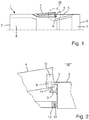
- a top view of a motor vehicle 1 shown in principle is shown.
- the motor vehicle 1 has a front area 2, a rear area 3 and a side door 4.
- the motor vehicle side door 4 is shown in an open position, the open position being characterized in that there is an opening gap S between the motor vehicle body 5 and the side door 4.
- a lock holder 6 can be seen, which in this exemplary embodiment is designed as a locking bolt.
- the opening device according to the invention is shown using the example of a motor vehicle door 4, this is not restrictive. Rather, it is conceivable to also use the opening device, for example, for a tailgate 7 located in the motor vehicle rear 3 or, for example, for a bonnet 8 located in the region of the motor vehicle front.
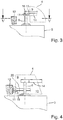
- FIG. 2 is an enlarged view of detail II from Fig. 1 shown in the area of the lock holder 6.
- the same components are provided with the same reference numbers in the figures.
- the detailed view II is shown in a section through the motor vehicle 1 above the lock holder 6.
- the opening device 9 is integrated in a motor vehicle door lock 10 and has an opening means 11 which interacts directly with the lock holder 6.
- the opening means 11 can be moved in the opening device such that the opening means 11 can be moved out of the motor vehicle door 4.
- a door seal 12 is fastened on folds 13 of the motor vehicle body 5.
- the door seal 12 preferably surrounds the motor vehicle door circumferentially and seals the interior of the motor vehicle 1 against the environment.
- the door seal 12 generates a force on the motor vehicle door 4 and in particular when the motor vehicle door is in the fully closed closed position.
- This door sealing force can be used by the motor vehicle door lock 10 to open the locking mechanism, in that only the pawl is removed from the catch and the door sealing force or the door sealing pressure causes the rotary catch to rotate, that is to say to open the locking mechanism.
- the opening device 9 then moves the motor vehicle door 4 completely into the motor vehicle door 4 in the open position.
- a further detailed representation is shown in the area of the lock holder 6 and door seal 12.
- the lock holder 6 is screwed to the motor vehicle body 5 as a locking bolt.
- Shown is a first raising means 11 in the form of a plunger 14 which acts directly on the locking bolt 6.
- the plunger 14 can, for example, be designed magnetically and, contrary to the exemplary embodiment shown, can also interact with the locking bolt 6 without the engagement means 15 engaging positively in the locking bolt 6.
- a combination of a plunger 14 and an actuating means 15 which positively engages in the locking bolt 6 is shown.
- the actuating means 15, which is embodied in a form-locking manner, has a conical tip 16 which engages in a key opening 17 of the locking bolt 6.
- the engagement means 15, which engages in the locking bolt 6 in a form-fitting manner can consist of a resilient material, such as, for example, plastic or spring steel, and / or rest resiliently in the key opening 17.
- the positive locking means 15 exerts sufficient force on the locking bolt 6 to hold the motor vehicle side door 4 in the open position or open position.
- Both in the Fig. 3 Display means 14, 15 shown can be moved out of the motor vehicle side door 4 at least in some areas.
- the Fig. 4 shows a further embodiment of an opening device 9 in the area of the lock holder 6.
- An opening means again designed as a plunger 16 11 acts on the locking bolt 6, the plunger 16 not moving out of the motor vehicle door 4.
- a further opening means 18 can be provided, which can be moved out of the motor vehicle door 4 and acts against the door seal 12.
- the opening means 18 can also be designed as a suction cup 19, for example. So that the opening means 18 can be received flush in the motor vehicle door 4, the motor vehicle door 4 or the motor vehicle door lock 10 has a recess 20 into which the opening means 18 can be moved in and out.
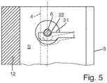
- FIG. 5 is a view along the line VV from the Fig. 4 reproduced.
- the deployment means in the form of a gripper finger 21 has a recess 22 which engages around the locking bolt 6 at least in a form-fitting manner and at least in regions.
- the motor vehicle side door 4, here indicated as a dashed line, is in an open position, so that there is a gap S into which an operator can reach and open the door completely. The opening position is thus shown. In a closed position, the motor vehicle door 4 would rest against the door seal 12 and there would be no gap S.
- the gripper finger 21 is able to move to the position shown in dashed lines. This can be done against a spring force in the interior of the motor vehicle door lock or the opening device, but the gripper finger 21 can also consist of a resilient material, so that there is sufficient contact pressure against the locking bolt that the motor vehicle door 4 is held securely in the open position, the operator but can grasp the motor vehicle door and open it without much resistance.
- the gripper finger 21 is additionally designed magnetically in order to enable the motor vehicle door to be held securely in the open position.
- the motor vehicle door 4 If the motor vehicle door 4 is in a closed position, the motor vehicle door 4 bears against the door seal 12. If the motor vehicle door lock 10 is now opened electrically, the motor vehicle door 4 is moved into the open position by the door seal pressure and by means of the opening device 9.
- the actuating means 11, 15, 18 or the actuator 11, 15, 18 moves linearly or quasi-linearly and is held magnetically on the lock bracket 6 and / or can be similar to a bonnet catch, such as in FIG Fig. 5 shown, move to the side, the door is held securely in the open position.
- the opening means in particular the actuator, tappet, suction cup and / or gripper finger, can be retracted.
Description
Die Erfindung betrifft ein Kraftfahrzeugschloss aufweisend ein Gesperre mit einer Drehfalle und mindestens einer Sperrklinke, wobei mittels der Sperrklinke eine Drehbewegung der Drehfalle sperrbar ist, eine Antriebseinrichtung, mit der die Sperrklinke aus einer Sperrstellung in eine Freigabestellung für das Gesperre überführbar ist und einer Ausstelleinrichtung, wobei mittels der Ausstelleinrichtung ein das Kraftfahrzeugschloss aufnehmendes Fahrzeugteil aus einer Schließstellung heraus in eine Öffnungsstellung bewegbar ist.The invention relates to a motor vehicle lock having a locking mechanism with a rotary latch and at least one pawl, wherein the rotary pawl can be locked by means of the locking pawl, a drive device with which the locking pawl can be transferred from a locking position into a release position for the locking mechanism and an opening device, wherein a vehicle part accommodating the motor vehicle lock can be moved from a closed position into an open position by means of the opening device.
Die Bedienung eines Kraftfahrzeugs wird durch elektronische und elektrische Hilfsmittel mehr und mehr vereinfacht. So ist das Ver- und Entriegeln mittels einer Funkfernsteuerung mittlerweile mehr zur Regel als zur Ausnahme geworden. Bekannt ist es ebenfalls, dass neben dem Ver- und Entriegeln eines Kraftfahrzeugschlosses auch ein elektrisches Öffnen des Schließmechanismusses, vorzugsweise eines Gesperres, ausgeführt werden kann. Ist das Gesperre geöffnet, so kann beispielsweise eine Kraftfahrzeugtür ohne die manuelle Betätigung eines Außenbetätigungsgriffes geöffnet werden.The operation of a motor vehicle is being simplified more and more by electronic and electrical aids. Locking and unlocking using a radio remote control has become more the rule than the exception. It is also known that in addition to locking and unlocking a motor vehicle lock, an electrical opening of the locking mechanism, preferably a locking mechanism, can also be carried out. If the locking mechanism is open, a motor vehicle door, for example, can be opened without the manual actuation of an outside operating handle.
Aus der
Aus der
Eine unmittelbar in einen Kraftfahrzeugtürverschluss integrierte Ausstelleinrichtung ist aus der
Ein Problem, das sich bei den bekannten Ausstelleinrichtung einstellt, ist das, dass nach einem Öffnen des Gesperres und einem Bewegen der Tür, Klappe oder Haube sich dieses Kraftfahrzeugteil in eine undefinierbare Position hinein bewegt. Je nach Lage oder Ausrichtung des Kraftfahrzeugs kann es dabei vorkommen, dass sich zum Beispiel eine Kraftfahrzeugtür in eine mehr oder weniger große Öffnungsstellung hinein bewegt. Dieser undefinierbare Zustand ist nicht gewollt und kann ebenfalls zu Behinderungen oder Schäden am Kraftfahrzeug führen.A problem that arises with the known opening device is that after opening the locking mechanism and moving the door, flap or hood, this motor vehicle part moves into an indefinable position. Depending on the position or orientation of the motor vehicle, it can happen that, for example, a motor vehicle door moves into a more or less large opening position. This indefinable state is not wanted and can also lead to disabilities or damage to the motor vehicle.
Aufgabe der Erfindung ist es, ein verbessertes Kraftfahrzeugschloss bereitzustellen. Darüber hinaus ist es Aufgabe der Erfindung, eine Möglichkeit zu schaffen, das Kraftfahrzeugteil in eine definierte Lage zu bringen, um Schäden oder Fehlbetätigungen zu vermeiden. Darüber hinaus ist es Aufgabe der Erfindung, eine konstruktiv einfache und kostengünstige Lösung bereitzustellen.The object of the invention is to provide an improved motor vehicle lock. In addition, it is an object of the invention to provide a way of bringing the motor vehicle part into a defined position in order to avoid damage or incorrect operation. In addition, it is an object of the invention to provide a structurally simple and inexpensive solution.
Die Lösung der Aufgabe erfolgt erfindungsgemäß durch die Merkmale der unabhängigen Ansprüche. Vorteilhafte Ausgestaltungen der Erfindung sind in den Unteransprüchen angegeben. Es wird darauf hingewiesen, dass die im Folgenden beschriebenen Ausführungsbeispiele nicht beschränkend sind, es sind vielmehr beliebige Variationsmöglichkeiten der in der Beschreibung und den Unteransprüchen beschriebenen Merkmale möglich.The object is achieved according to the invention by the features of the independent claims. Advantageous embodiments of the invention are specified in the subclaims. It is pointed out that the exemplary embodiments described below are not restrictive; rather, any possible variations of the features described in the description and the subclaims are possible.
Gemäß dem Patentanspruch 1 wird die Aufgabe der Erfindung dadurch gelöst, dass ein Kraftfahrzeugschloss bereitgestellt wird, aufweisend ein Gesperre mit einer Drehfalle und mindestens einer Sperrklinke, wobei mittels der Sperrklinke eine Drehbewegung der Drehfalle sperrbar ist, eine Antriebseinrichtung, mit der die Sperrklinke aus einer Sperrstellung in eine Freigabestellung für das Gesperre überführbar ist und einer Ausstelleinrichtung, wobei mittels der Ausstelleinrichtung ein das Kraftfahrzeugschloss aufnehmendes Fahrzeugteil aus einer Schließstellung heraus in eine Öffnungsstellung bewegbar ist und wobei die Ausstelleinrichtung das Kraftfahrzeugteil in seiner Öffnungsstellung hält, so dass ein selbständiges Öffnen des Kraftfahrzeugteils über die Öffnungsstellung hinaus unterbindbar ist, wobei die Ausstelleinrichtung ein Ausstellmittel aufweist, wobei mittels des Ausstellmittels das Kraftfahrzeugteil in die Öffnungsstellung bewegbar ist, wobei das Ausstellmittel einen aus dem Kraftfahrzeugschloss heraus bewegbaren Stößel aufweist. Durch die erfindungsgemäße Ausbildung der Ausstelleinrichtung ist nun die Möglichkeit geschaffen, ein unbeabsichtigtes Öffnen des Kraftfahrzeugteils zu unterbinden. Die Ausstelleinrichtung hält das Kraftfahrzeugteil in seiner geöffneten Stellung, so dass ein vollständiges selbständiges Öffnen des Kraftfahrzeugteils sicher verhindert wird. Insbesondere ermöglicht es die Öffnungsstellung dem Bediener, die Tür zu ergreifen und bequem zu öffnen. Die Öffnungsstellung kann dabei je nach Kraftfahrzeugteil variieren. Die Öffnungsstellung ist aber bevorzugt die Stellung, in der ein Hineingreifen in einen sich durch die Öffnungsstellung bildenden Spalt ermöglicht wird. Dabei wird das Kraftfahrzeugteil, das zum Beispiel eine Tür, eine Klappe, eine Motorhaube, eine Schiebetür oder beispielsweise auch ein Handschuhfach sein kann, von der Ausstelleinrichtung in der Öffnungsstellung fixiert bzw. gehalten. Mittels des Ausstellmittels ist das Kraftfahrzeugteil in die Öffnungsstellung bewegbar. Durch die Verwendung des Ausstellmittels kann zielgerichtet auf Bestandteile des Kraftfahrzeuges im Bereich des Kraftfahrzeugschlosses eingewirkt werden. Insbesondere ist es dabei möglich zum Beispiel ein separates Ausstellmittel im Kraftfahrzeugschloss zu bewegen, das mit einem dem Kraftfahrzeugschloss zusammenwirkenden weiteren Bauteil des Kraftfahrzeuges zusammenwirkt, so dass eine Relativkraft zwischen Schloss und demweiterem Bauteil erzielbar ist. Erfindungsgemäß ist das Ausstellmittel als ein aus dem Kraftfahrzeugschloss heraus bewegbarer Stößel gebildet. Dabei kann der Stößel zum Beispiel eine Verzahnung aufweisen, über die der Stößel antreibbar und aus dem Schloss heraus bewegbar ist. Je nach Einsatzgebiet des erfindungsgemäßen Kraftfahrzeugschlosses ist es dann möglich, einen mehr oder weniger großen Hub sowohl durch den Antrieb des Ausstellmittels als auch über die Länge des Ausstellmittels einzustellen.According to claim 1, the object of the invention is achieved in that a motor vehicle lock is provided, having a locking mechanism with a rotary latch and at least one pawl, wherein by means of the locking pawl a rotary movement of the rotary latch can be locked, a drive device with which the locking pawl can be removed from a locking position into a release position for the locking mechanism and an opening device, whereby the opening device can be used to move a vehicle part receiving the motor vehicle lock from a closed position into an open position and the opening device holds the motor vehicle part in its open position, so that an independent opening of the motor vehicle part beyond the open position can be prevented, the opening device having an opening means, the opening part being able to move the motor vehicle part into the opening position, the opening means having a plunger which can be moved out of the motor vehicle lock. The design of the opening device according to the invention now creates the possibility of preventing unintentional opening of the motor vehicle part. The opening device holds the motor vehicle part in its open position, so that a completely independent opening of the motor vehicle part is reliably prevented. In particular, the open position enables the operator to grasp the door and open it comfortably. The opening position can vary depending on the motor vehicle part. However, the open position is preferably the position in which reaching into a gap formed by the open position is made possible. The motor vehicle part, which can be, for example, a door, a flap, a bonnet, a sliding door or, for example, also a glove box, is fixed or held in the open position by the opening device. The motor vehicle part can be moved into the open position by means of the opening means. By using the opening means, components of the motor vehicle in the area of the motor vehicle lock can be targeted. In particular, it is possible, for example, to move a separate opening means in the motor vehicle lock, which interacts with another component of the motor vehicle that interacts with the motor vehicle lock, so that a relative force between the lock and the further component can be achieved. According to the invention, the opening means is designed as a plunger which can be moved out of the motor vehicle lock. The plunger can, for example, have a toothing via which the plunger can be driven and moved out of the lock. Depending on the area of application of the motor vehicle lock according to the invention, it is then possible to set a more or less large stroke both by driving the actuating means and over the length of the actuating means.
Die Erfindung bezieht sich auf ein Kraftfahrzeugschloss, wobei hier nicht ausschließlich ein Kraftfahrzeugtürschloss beansprucht wird, sondern ebenfalls Schlösser gemeint sein können, die als Motorhaubenschlösser, Heckklappenschlösser, Schiebetürenschlösser, Tankschlösser oder Klappenschlösser, sowie all jene Kraftfahrzeugteile, die eine automatische Öffnungseinrichtung aufweisen und vor einem vollständigen Öffnen geschützt werden sollen. Bevorzugt bezieht sich die Erfindung auf Kraftfahrzeugtürschlösser mit einem Gesperre, aufweisend eine Drehfalle und mindestens eine Sperrklinke.The invention relates to a motor vehicle lock, here not only a motor vehicle door lock is claimed, but also locks that are meant as bonnet locks, tailgate locks, sliding door locks, tank locks or flap locks, as well as all those motor vehicle parts that have an automatic opening device and a complete one Open should be protected. The invention preferably relates to motor vehicle door locks with a locking mechanism, comprising a rotary latch and at least one pawl.
Die Drehfalle ist bevorzugt drehbar im Kraftfahrzeugschloss aufgenommen und wirkt mit einem Schlosshalter oder Schlossbügel zusammen. Bewirkt das Zusammenspiel zwischen Schlosshalter und Drehfalle beispielsweise eine Drehbewegung der Drehfalle in Schließrichtung, so wirkt die Sperrklinke zum Beispiel federbelastet mit der Drehfalle zusammen, so dass die Drehfalle in ihrer Schließstellung fixiert bzw. gehalten wird. Die Sperrklinke sperrt die Drehbewegung der Drehfalle.The rotary latch is preferably rotatably received in the motor vehicle lock and interacts with a lock holder or lock shackle. If the interplay between the lock holder and the rotary latch causes, for example, a rotary movement of the rotary latch in the closing direction, the pawl interacts with the rotary latch, for example spring-loaded, so that the rotary latch is fixed or held in its closed position. The pawl blocks the rotary movement of the catch.
Eine bevorzugt elektrisch betätigte Antriebseinrichtung wirkt auf die Sperrklinke und kann die Sperrklinke aus ihrer Sperrstellung in eine Freigabestellung überführen, so dass die Drehfalle frei wird und das Gesperre öffnet. Derartige Kraftfahrzeugschlösser werden auch als elektrische Schlösser oder E-Schlösser und der Vorgang des Entsperrens als elektrisches Öffnen bezeichnet. Insbesondere bei E-Schlössern, bei denen das Gesperre zum Beispiel elektrisch freigegeben wird, kann zum Beispiel ein Türdichtungsdruck dazu dienen, das Kraftfahrzeugteil aus einer Schließstellung in eine Öffnungsstellung zu überführen.A preferably electrically actuated drive device acts on the pawl and can move the pawl from its locked position into a release position, so that the catch is released and the locking mechanism opens. Such motor vehicle locks are also referred to as electrical locks or e-locks and the unlocking process as electrical opening. In particular in the case of e-locks in which the locking mechanism is released electrically, for example, a door seal pressure can serve, for example, to transfer the motor vehicle part from a closed position into an open position.
Ist nun beispielsweise der Türdichtungsdruck nicht ausreichend um die Kraftfahrzeugtür aus der Schließstellung in eine Öffnungsstellung zu bewegen, so dass ein Bediener die Tür ergreifen und vollständig öffnen kann, so dient die Ausstelleinrichtung dazu, die Kraftfahrzeugtür in eine Öffnungsstellung zu überführen. Steht das Kraftfahrzeug dabei zum Beispiel in einem ungünstigen Winkel, zum Beispiel auf einer geneigten Straße, so kann es vorkommen, dass der Bediener das E-Schloss elektrisch öffnet und dass die Kraftfahrzeugtür aus der Schließstellung in eine Stellung weit über die Öffnungsstellung hinaus selbständig öffnet. Dies kann zu Behinderungen, Beschädigungen an der Tür oder schlimmstenfalls zu Verletzungen führen. Die erfindungsgemäße Ausstelleinrichtung mit einer Haltefunktion ermöglicht es hierbei, dass die Kraftfahrzeugtür oder das Kraftfahrzeugteil in der Öffnungsstellung positioniert bzw. gehalten wird.If, for example, the door seal pressure is not sufficient to move the motor vehicle door from the closed position into an open position so that an operator can grasp the door and open it completely, the opening device serves to bring the motor vehicle door into an open position. If, for example, the motor vehicle is at an unfavorable angle, for example on an inclined road, it can happen that the operator opens the electric lock electrically and that the motor vehicle door opens automatically from the closed position into a position far beyond the open position. This can lead to disabilities, damage to the door or, in the worst case, injuries. The opening device according to the invention with a holding function enables the motor vehicle door or the motor vehicle part to be positioned or held in the open position.
In einer alternativen Ausführungsform der Erfindung ist die Ausstelleinrichtung in das Kraftfahrzeugschloss zumindest teilweise integriert. Ist die Ausstelleinrichtung Teil des Kraftfahrzeugschlosses, so kann einerseits Bauraum eingespart werden und darüber hinaus wird die Montage der Ausstelleinrichtung erleichtert. Als Teil des Kraftfahrzeugschlosses kann darüber hinaus auch auf die elektrischen oder elektronischen Bestandteile des Kraftfahrzeuges zurückgegriffen werden, so dass darüber hinaus die Ausstelleinrichtung keine separate Stromversorgung benötigt. Ebenso könnte die Ausstelleinrichtung derart im Kraftfahrzeugschloss angeordnet sein, dass keine zusätzlichen Öffnungen in die Kraftfahrzeugtür eingelassen werden müssen oder dass vorhandene Öffnungen lediglich geringfügig modifiziert werden müssen, um eine erfindungsgemäße Ausstelleinrichtung in ein Kraftfahrzeug zu integrieren.In an alternative embodiment of the invention, the opening device is at least partially integrated into the motor vehicle lock. If the opening device is part of the motor vehicle lock, construction space can be saved on the one hand and the assembly of the opening device is also facilitated. As part of the motor vehicle lock, the electrical or electronic components of the motor vehicle can also be used, so that the opening device does not require a separate power supply. Likewise, the issuing device could in Motor vehicle lock can be arranged that no additional openings have to be let into the motor vehicle door or that existing openings only have to be slightly modified in order to integrate an opening device according to the invention into a motor vehicle.
Bildet die Antriebseinrichtung einen Antrieb für die Ausstelleinrichtung, so ergibt sich eine weitere Ausführungsform der Erfindung. Als Antriebseinrichtung zum elektrischen Öffnen des Kraftfahrzeugschlosses dient bevorzugt ein Elektromotor, der beispielsweise mit einem Getriebe auf eine Stelleinrichtung einwirkt, so dass die Sperrklinke von der Drehfalle lösbar ist. Wird nun der im Kraftfahrzeugschloss vorhandene Elektromotor als Antriebseinrichtung für die Ausstelleinrichtung eingesetzt, so kann auf einen weiteren Antrieb für die Ausstelleinrichtung verzichtet werden. Dies reduziert Bauraum, Kosten und Bauteile, so dass sich eine Reihe von Vorteilen aus einer mehrere Funktionen umfassenden Antriebseinrichtung ergeben.If the drive device forms a drive for the opening device, a further embodiment of the invention results. An electric motor is preferably used as the drive device for the electrical opening of the motor vehicle lock, which acts, for example, on an actuating device with a gear, so that the pawl can be released from the rotary latch. If the electric motor present in the motor vehicle lock is now used as a drive device for the opening device, a further drive for the opening device can be dispensed with. This reduces installation space, costs and components, so that a number of advantages result from a drive device comprising several functions.
Rückt das Ausstellmittel mit einem Schlosshalter, insbesondere einem Schlosshalterbolzen oder Schlosshalterbügel, zusammen, so ergibt sich eine weitere Ausführungsform der Erfindung. Das Gesperre wirkt beim Einsatz des Kraftfahrzeugschlosses in einer Seitentür, Schiebetür oder Klappe zumeist mit einem am Kraftfahrzeug befestigten Schlosshalter zusammen. Ein Bewegen des Gesperres in Richtung des Schlosshalters bewirkt dabei, dass das Gesperre gesperrt wird. Eine umgekehrte Bewegung ist natürlich ebenso vorstellbar und möglich. Wird nun aufgrund mangelndem Türdichtungsdruckes die Tür nicht vollständig in eine Öffnungsstellung bewegt, so kann das Ausstellmittel unmittelbar auf den Schlosshalter einwirken und beispielsweise mit einem Stößel die Tür in eine Öffnungsstellung bewegen. Dabei ist das Stellmittel bzw. Ausstellmittel in unmittelbarer Nähe des Gesperres angeordnet, was wiederum vorteilhaft in Bezug auf den Bauraum ist.If the opening means moves together with a lock holder, in particular a lock holder bolt or lock holder bracket, a further embodiment of the invention results. When using the motor vehicle lock in a side door, sliding door or flap, the locking mechanism mostly interacts with a lock holder attached to the motor vehicle. Moving the locking mechanism in the direction of the lock holder causes the locking mechanism to be locked. A reverse movement is of course also conceivable and possible. If the door is not completely moved into an open position due to a lack of door seal pressure, the opening means can act directly on the lock holder and, for example, move the door into an open position with a plunger. The actuating means or exhibiting means is arranged in the immediate vicinity of the locking mechanism, which in turn is advantageous in relation to the installation space.
Eine weitere Ausführungsform ergibt sich dann, wenn das Ausstellmittel mit einem Kraftfahrzeugelement, insbesondere einer Türdichtung zusammenwirkt. Das Ausstellmittel als Bestandteil des Kraftfahrzeugschlosses ist im geschlossenen Zustand der beispielsweise Kraftfahrzeugtür in unmittelbarer Nähe der Dichtung der Tür angeordnet oder liegt sogar unmittelbar an der Türdichtung an. In vorteilhafter Weise kann nun ein Ausstellmittel auf die Türdichtung einwirken und eine Relativkraft erzeugen, die die Tür in eine Öffnungsstellung bewegt. Die Tür wird somit aus der Schließstellung in die Öffnungsstellung bewegt bzw. gedrückt.A further embodiment results when the opening means cooperates with a motor vehicle element, in particular a door seal. The opening means as part of the motor vehicle lock is arranged in the closed state of the motor vehicle door, for example, in the immediate vicinity of the door seal or even lies directly on the door seal. Advantageously, an opening means can now act on the door seal and generate a relative force that moves the door into an open position. The door is thus moved or pressed from the closed position into the open position.
In vorteilhafter Weise kann das Ausstellmittel formschlüssig und/oder kraftschlüssig mit einem weiteren Bauteil des Kraftfahrzeugs, und insbesondere einem Schlosshalter zusammenwirken. Durch die Ausbildung geeigneter Formen kann das Ausstellmittel unmittelbar mit dem Schlosshalter zusammenwirken. Ist beispielsweise ein Schlosshalterbolzen im Einsatz, so kann ein Formschluss des Ausstellmittels mit einer Öffnung, beispielsweise einer Vertiefung im Schlosshalterbolzen, der zur Montage dient, formschlüssig zusammenwirken und beispielsweise in die Öffnung eingreifen. Hierdurch ist ein äußerst kostengünstiges und sicheres Halten der zum Beispiel Kraftfahrzeugtür möglich.Advantageously, the opening means can cooperate positively and / or non-positively with another component of the motor vehicle, and in particular a lock holder. Through the formation of suitable shapes, the opening means can interact directly with the lock holder. Is For example, a lock holder bolt in use, a positive engagement of the exposing means with an opening, for example a recess in the lock holder bolt, which is used for assembly, can interact positively and, for example, engage in the opening. This enables extremely cost-effective and secure holding of the motor vehicle door, for example.
Es ist ebenfalls vorstellbar, dass das Ausstellmittel den Schlosshalter zumindest bereichsweise formschlüssig umgreift, so dass einerseits eine ausreichende Kraft auf den Schlosshalter ausübbar ist und dass darüber hinaus ein Formschluss in der Weise gewährleistet wird, dass eine Positionierung, das heißt ein Halten der Kraftfahrzeugtür in der Öffnungsstellung ermöglicht wird.It is also conceivable that the opening means encompasses the lock holder in a form-fitting manner at least in some areas, so that on the one hand a sufficient force can be exerted on the lock holder and that a positive fit is also ensured in such a way that positioning, that is to say holding the motor vehicle door in the Opening position is made possible.
Je nach Ausbildung des Ausstellmittels ist aber auch eine kraftschlüssige Verbindung zwischen Ausstellmittel und Schlosshalter vorstellbar. Wird beispielsweise das Ausstellmittel in einer Variante mit einem Werkstoff, wie beispielsweise Kunststoff oder Gummi beschichtet, so kann auch ein ausreichender Kraftschluss zwischen Ausstellmittel und Schlosshalter zur Verfügung gestellt werden, um die Tür oder Klappe in ihrer Öffnungsstellung zu halten, wobei bevorzugt ein Reibschluss erzeugt wird. Es ist aber auch eine Kombination aus Reibschluss und Formschluss vorstellbar.Depending on the design of the exhibition means, a non-positive connection between the exhibition means and the lock holder is also conceivable. If, for example, the extension means is coated with a material such as plastic or rubber in a variant, a sufficient frictional connection between the extension means and the lock holder can also be provided in order to keep the door or flap in its open position, a frictional engagement preferably being generated . However, a combination of frictional locking and positive locking is also conceivable.
In einer weiteren Ausführungsform wirkt das Ausstellmittel mittels einer magnetischen Kraft mit dem Schlosshalter zusammen. Wird das Ausstellmittel zum Beispiel magnetisch ausgeführt, so ist ein sehr leichtes Halten des Kraftfahrzeugteils in der Öffnungsstellung ermöglicht. Eine Vielzahl von Bauteilen eines Kraftfahrzeugs sind ferromagnetisch, so dass das Ausstellmittel in der Lage ist, mit den weiteren Bestandteilen des Kraftfahrzeugs zusammenzuwirken und eine magnetische Haltekraft auszuüben. Bevorzugt wirkt das magnetische Ausstellmittel mit dem Schlosshalter zusammen und kann somit die zum Beispiel Kraftfahrzeugtür in der Öffnungsstellung halten. Ein Bediener kann in dieser Öffnungsstellung die Tür ergreifen und das Ausstellmittel vom Schlosshalter lösen. Dazu muss lediglich die magnetische Kraft zwischen Ausstellmittel und Schlosshalter überwunden werden. Dies gibt dem Nutzer des Kraftfahrzeugs die Möglichkeit einer haptischen Rückmeldung und somit das Gefühl einer Sicherheit, dass die Tür in der Öffnungsstellung sicher gehalten ist. Dies gilt natürlich ebenso für ein form- und/oder reib- und/oder kraftschlüssiges Halten des Kraftfahrzeugteils.In a further embodiment, the opening means cooperates with the lock holder by means of a magnetic force. If, for example, the raising means is designed magnetically, the motor vehicle part can be held very easily in the open position. A large number of components of a motor vehicle are ferromagnetic, so that the positioning means is able to interact with the other components of the motor vehicle and to exert a magnetic holding force. The magnetic opening means preferably interacts with the lock holder and can thus hold the motor vehicle door in the open position, for example. In this open position, an operator can grasp the door and the opening device from the lock holder to solve. All that needs to be done is to overcome the magnetic force between the opening means and the lock holder. This gives the user of the motor vehicle the possibility of haptic feedback and thus the feeling of security that the door is held securely in the open position. Of course, this also applies to a positive and / or frictional and / or non-positive holding of the motor vehicle part.
Ist das Kraftfahrzeugteil eine Kraftfahrzeugtür, so ergibt sich eine bevorzugte Ausführungsform der Erfindung, wobei die Kraftfahrzeugtür mittels des Ausstellmittels so weit in eine Öffnungsstellung bringbar ist, dass in einen Öffnungsspalt zwischen Kraftfahrzeugtür und Karosserie eingreifbar ist. Insbesondere für eine Kraftfahrzeugtür eignet sich die Verwendung eines Ausstellmittels, das die Kraftfahrzeugtür bevorzugt als elektrische Tür, das heißt mit einem E-Schloss versehene Tür ausführbar ist, wobei eine derartige Tür zum Beispiel auch ohne Außenbetätigungsgriff ausführbar ist. Dies ist insbesondere aus ästhetischen Gründen und bei der Formgebung des Kraftfahrzeugs von Vorteil.If the motor vehicle part is a motor vehicle door, this results in a preferred embodiment of the invention, the motor vehicle door being able to be brought into an open position so far by means of the opening means that it is possible to engage in an opening gap between the motor vehicle door and the body. Particularly suitable for a motor vehicle door is the use of an opening means, which the motor vehicle door is preferably designed as an electrical door, that is to say a door provided with an E-lock, such a door also being able to be implemented, for example, without an external operating handle. This is particularly advantageous for aesthetic reasons and when shaping the motor vehicle.
Kann mittels der erfindungsgemäßen Ausstelleinrichtung einerseits ein Spalt zwischen Kraftfahrzeugtür und weiteren Bestandteilen des Kraftfahrzeugs erzielt werden und die Tür in eine Öffnungsstellung bewegt werden, so kann der Bediener einerseits sicher sein, dass sich die Tür nicht selbständig öffnet und andererseits besteht auch die Möglichkeit, mittels des Ausstellmittels bzw. der Ausstelleinrichtung die Tür wieder zumindest bereichsweise in eine Schließstellung zurückzubewegen. Hierdurch wird ein automatisches Öffnen und Schließen zumindest im Bereich zwischen einer Schließstellung der Tür und einer Öffnungsstellung der Tür ermöglicht. Mittels des Ausstellmittels bzw. der Ausstelleinrichtung kann die Kraftfahrzeugtür dann von einer Öffnungsstellung in eine Schließstellung und zumindest so weit in eine Schließstellung zurückbewegt werden, dass ein automatisches Zuziehen zum Beispiel mittels des Gesperres ermöglicht wird.If on the one hand a gap can be achieved between the motor vehicle door and other components of the motor vehicle and the door can be moved into an open position by means of the opening device according to the invention, on the one hand the operator can be sure that the door does not open automatically and on the other hand there is also the possibility of using the Moving means or the exhibiting device to move the door back into a closed position at least in some areas. This enables automatic opening and closing at least in the area between a closed position of the door and an open position of the door. By means of the opening means or the opening device, the motor vehicle door can then be moved back from an open position into a closed position and at least as far into a closed position that automatic closing is made possible, for example, by means of the locking mechanism.
Nachfolgend wird die Erfindung unter Bezugnahme auf die anliegenden Zeichnungen anhand bevorzugter Ausführungsformen näher erläutert.The invention is explained in more detail below with reference to the attached drawings using preferred embodiments.
Es zeigen:
- Fig. 1
- eine Draufsicht auf ein Kraftfahrzeug mit einer sich in einer Öffnungsstellung befindlichen Seitentür,
- Fig. 2
- eine Detailansicht auf die sich in der Öffnungsstellung befindenden Seitentür gemäß der
Fig. 1 und im Besonderen der Ansicht II, in einer Schnittdarstellung, die die prinzipielle Anordnung zwischen einem in der Seitentür befindlichen Kraftfahrzeugschloss und Ausstelleinrichtung zeigt, die mit einem Schlosshalter zusammenwirkt, - Fig. 3
- wiederum eine vergrößerte Darstellung des Schnitts gemäß der
Fig. 2 im Bereich des Schlosshalters, die das Zusammenspiel zwischen Schlosshaltern und Ausstelleinrichtung in einem Ausführungsbeispiel verdeutlicht, - Fig. 4
- ebenfalls eine Schnittdarstellung gemäß der
Fig. 2 im Bereich des Schlosshalters mit alternativen Ausführungsformen von Ausstelleinrichtungen und - Fig. 5
- eine Ansicht auf einen Schlosshalter gemäß der Linie V-V aus
Fig. 3 mit einer weiteren alternativen Ausführungsform eines Ausstellmittels.
- Fig. 1
- 3 shows a plan view of a motor vehicle with a side door located in an open position,
- Fig. 2
- a detailed view of the side door in the open position according to the
Fig. 1 and in particular view II, in a sectional view, which shows the basic arrangement between a motor vehicle lock located in the side door and the opening device, which interacts with a lock holder, - Fig. 3
- again an enlarged representation of the section according to the
Fig. 2 in the area of the lock holder, which illustrates the interaction between lock holders and opening device in one exemplary embodiment, - Fig. 4
- also a sectional view according to the
Fig. 2 in the area of the lock holder with alternative embodiments of opening devices and - Fig. 5
- a view of a lock holder according to the line VV
Fig. 3 with a further alternative embodiment of a display means.
In der
In der
In der
Die
In der
Wird die Kraftfahrzeugtür 4 nun aus der in der
Befindet sich die Kraftfahrzeugtür 4 in einer Schließstellung, so liegt die Kraftfahrzeugtür 4 an der Türdichtung 12 an. Wird nun das Kraftfahrzeugtürschloss 10 elektrisch geöffnet, so wird die Kraftfahrzeugtür 4 durch den Türdichtungsdruck und mittels der Ausstelleinrichtung 9 in die Öffnungsstellung bewegt. Dabei verfährt das Ausstellmittel 11, 15, 18 bzw. der Aktuator 11, 15, 18 linear oder quasi linear und hält sich am Schlosshalterbügel 6 magnetisch fest und/oder lässt sich ähnlich einem Motorhaubenfanghaken, wie beispielsweise in der
- 11
- KraftfahrzeugMotor vehicle
- 22nd
- KraftfahrzeugfrontMotor vehicle front
- 33rd
- KraftfahrzeugheckMotor vehicle rear
- 44th
- Seitentür, KraftfahrzeugseitentürSide door, motor vehicle side door
- 55
- KraftfahrzeugkarosserieMotor vehicle body
- 66
- Schlosshalter, Schließbolzen, SchlosshalterbügelLock holder, locking bolt, lock holder bracket
- 77
- HeckklappeTailgate
- 88th
- MotorhaubeEngine Hood
- 99
- AusstelleinrichtungIssuing facility
- 1010th
- KraftfahrzeugtürschlossMotor vehicle door lock
- 11, 15, 1811, 15, 18
- Ausstellmittel, AktuatorDisplay means, actuator
- 1212
- TürdichtungDoor seal
- 1313
- AbkantungenBevels
- 1414
- StößelPestle
- 1616
- kegelförmige Spitzeconical tip
- 1717th
- SchlüsselöffnungKey opening
- 1919th
- Saugnapfsuction cup
- 2020th
- Vertiefungdeepening
- 2121st
- GreiferfingerGripper fingers
- 2222
- AusnehmungRecess
- SS
- Spalt, ÖffnungsspaltGap, opening gap
Claims (8)
- Motor vehicle lock comprising a locking mechanism having a rotary latch and at least one pawl, it being possible for a rotary movement of the rotary latch to be blocked by means of the pawl, a drive device by means of which the pawl can be transferred from a blocking position into a release position for the locking mechanism, and an adjusting device (11, 15, 18), a vehicle part (4) that accommodates the motor vehicle lock being movable from a closed position into an open position by means of the adjusting device (11, 15, 18), characterized in that the adjusting device (11, 15, 18) holds the motor vehicle part (4) in the open position thereof such that the motor vehicle part (4) can be prevented from opening independently beyond the open position, the adjusting device (11, 15, 18) comprising an adjusting means (11, 15, 18), it being possible to move the motor vehicle part (4) into the open position by means of the adjusting means (11, 15, 18), the adjusting means (11, 15, 18) comprising a plunger (14) that can be moved out of the motor vehicle lock.
- Motor vehicle lock according to claim 1, characterized in that the adjusting device (11, 15, 18) is at least partially integrated into the motor vehicle lock.
- Motor vehicle lock according to either claim 1 or claim 2, characterized in that the drive device forms a drive for the adjusting device (11, 15, 18).
- Motor vehicle lock according to claim 1, characterized in that the adjusting means (11, 15, 18) cooperates with a lock holder (6), lock holder bolt or lock holder bracket.
- Motor vehicle lock according to claim 1, characterized in that the adjusting means (11, 15, 18) cooperates with a motor vehicle element (12), in particular a door seal (12).
- Motor vehicle lock according to any of claims 1 to 5, characterized in that the adjusting means (11, 15, 18) cooperates form-fittingly and/or force-fittingly with the lock holder (6).
- Motor vehicle lock according to any of claims 1 to 6, characterized in that the adjusting means (11, 15, 18) cooperates with the lock holder (6) by means of a magnetic force.
- Motor vehicle lock according to any of claims 1 to 7, characterized in that the motor vehicle part (4) is a motor vehicle door (4) and in that the motor vehicle door (4), by means of the adjusting means (11, 15, 18), can be brought so far into an open position that it is possible to engage into an opening gap (S) between the motor vehicle door (4) and a motor vehicle body (5).
Priority Applications (1)
| Application Number | Priority Date | Filing Date | Title |
|---|---|---|---|
| EP20164381.4A EP3699379B1 (en) | 2015-03-27 | 2016-03-22 | Motor vehicle lock |
Applications Claiming Priority (2)
| Application Number | Priority Date | Filing Date | Title |
|---|---|---|---|
| DE102015003918.0A DE102015003918A1 (en) | 2015-03-27 | 2015-03-27 | Motor vehicle lock |
| PCT/DE2016/100133 WO2016155699A1 (en) | 2015-03-27 | 2016-03-22 | Motor vehicle lock |
Related Child Applications (2)
| Application Number | Title | Priority Date | Filing Date |
|---|---|---|---|
| EP20164381.4A Division EP3699379B1 (en) | 2015-03-27 | 2016-03-22 | Motor vehicle lock |
| EP20164381.4A Division-Into EP3699379B1 (en) | 2015-03-27 | 2016-03-22 | Motor vehicle lock |
Publications (2)
| Publication Number | Publication Date |
|---|---|
| EP3274529A1 EP3274529A1 (en) | 2018-01-31 |
| EP3274529B1 true EP3274529B1 (en) | 2020-05-27 |
Family
ID=56344946
Family Applications (2)
| Application Number | Title | Priority Date | Filing Date |
|---|---|---|---|
| EP16734552.9A Active EP3274529B1 (en) | 2015-03-27 | 2016-03-22 | Motor vehicle lock |
| EP20164381.4A Active EP3699379B1 (en) | 2015-03-27 | 2016-03-22 | Motor vehicle lock |
Family Applications After (1)
| Application Number | Title | Priority Date | Filing Date |
|---|---|---|---|
| EP20164381.4A Active EP3699379B1 (en) | 2015-03-27 | 2016-03-22 | Motor vehicle lock |
Country Status (6)
| Country | Link |
|---|---|
| US (1) | US10975600B2 (en) |
| EP (2) | EP3274529B1 (en) |
| JP (1) | JP6747749B2 (en) |
| CN (1) | CN107429528B (en) |
| DE (2) | DE102015003918A1 (en) |
| WO (1) | WO2016155699A1 (en) |
Families Citing this family (15)
| Publication number | Priority date | Publication date | Assignee | Title |
|---|---|---|---|---|
| US10458171B2 (en) * | 2016-09-19 | 2019-10-29 | Ford Global Technologies, Llc | Anti-pinch logic for door opening actuator |
| US11008780B2 (en) * | 2016-12-23 | 2021-05-18 | Magna Closures, Inc. | Power door presenter with latching feature |
| US11274477B2 (en) | 2017-06-05 | 2022-03-15 | Magna Closures Inc. | Integrated door presentment mechanism for a latch |
| US10633893B2 (en) * | 2018-01-02 | 2020-04-28 | Ford Global Technologies, Llc | Door actuator with retraction device |
| DE102018008212A1 (en) * | 2018-10-17 | 2019-12-19 | Daimler Ag | Active door opening support |
| DE102018221230A1 (en) * | 2018-12-07 | 2020-06-10 | Volkswagen Aktiengesellschaft | Locking system for a locking element, vehicle |
| DE102019127081A1 (en) * | 2019-10-09 | 2021-04-15 | Kiekert Aktiengesellschaft | Device for setting up a component that is movably arranged on a motor vehicle |
| DE102019135418A1 (en) | 2019-12-20 | 2021-06-24 | Kiekert Aktiengesellschaft | Motor vehicle door lock |
| DE102020110812A1 (en) | 2020-04-21 | 2021-10-21 | Kiekert Aktiengesellschaft | Motor vehicle |
| DE102020110797A1 (en) | 2020-04-21 | 2021-10-21 | Kiekert Aktiengesellschaft | Motor vehicle flap, in particular motor vehicle door |
| US20230211725A1 (en) | 2020-04-21 | 2023-07-06 | Kiekert Ag | Motor vehicle |
| DE102020124240A1 (en) * | 2020-09-17 | 2022-03-17 | Kiekert Aktiengesellschaft | Installation device for a motor vehicle door element |
| DE102020133915A1 (en) | 2020-12-17 | 2022-06-23 | Kiekert Aktiengesellschaft | motor vehicle lock |
| DE102021132120A1 (en) | 2021-12-07 | 2023-06-07 | Kiekert Aktiengesellschaft | Combined motor vehicle lock |
| DE102022106523A1 (en) | 2022-03-21 | 2023-09-21 | Kiekert Aktiengesellschaft | Setting up device for a door element of a motor vehicle |
Citations (7)
| Publication number | Priority date | Publication date | Assignee | Title |
|---|---|---|---|---|
| DE19700887A1 (en) | 1997-01-14 | 1998-07-16 | Ewald Witte Gmbh & Co Kg | Fastening for vehicle tailgate or rear door , with motor operated closure element |
| JP2005163357A (en) | 2003-12-02 | 2005-06-23 | Mitsui Mining & Smelting Co Ltd | Door opening/closing device |
| JP2005256313A (en) * | 2004-03-09 | 2005-09-22 | Oi Seisakusho Co Ltd | Door opening device for vehicle |
| DE202005018026U1 (en) * | 2004-11-17 | 2006-03-30 | Brose Fahrzeugteile Gmbh & Co. Kommanditgesellschaft, Coburg | Tail unit for motor vehicle has tailgate pivoting drive and at least one further functional component combined with unit support to form module for mounting in vehicle body rear end region |
| JP2007120277A (en) | 2005-10-28 | 2007-05-17 | Shuichi Okubo | Hinged door partly-opening device for car |
| EP2733292A2 (en) * | 2012-11-20 | 2014-05-21 | Aisin Seiki Kabushiki Kaisha | Door actuating apparatus |
| WO2015144526A1 (en) * | 2014-03-22 | 2015-10-01 | Brose Schliesssysteme Gmbh & Co. Kg | Motor vehicle lock assembly |
Family Cites Families (54)
| Publication number | Priority date | Publication date | Assignee | Title |
|---|---|---|---|---|
| US1447846A (en) * | 1922-01-10 | 1923-03-06 | Edgar A Hill | Extension hasp |
| US2227144A (en) * | 1939-05-18 | 1940-12-31 | Chicago Forging & Mfg Co | Lifting means for automobile hoods |
| US2199369A (en) * | 1939-06-29 | 1940-04-30 | Ottorino Bonomi | Door holder |
| US2618497A (en) * | 1949-09-21 | 1952-11-18 | Walter D Gardels | Lockable trunk lid extension for automobiles |
| US2742312A (en) * | 1951-06-14 | 1956-04-17 | Joseph H Oswald | Opening closure panel and fastening means |
| US2683447A (en) * | 1952-05-05 | 1954-07-13 | Tappan Stove Co | Closure mechanism for cooking range ovens |
| US2857617A (en) * | 1955-05-27 | 1958-10-28 | Gen Motors Corp | Door check and hold-open |
| US3003800A (en) * | 1960-09-13 | 1961-10-10 | Gen Motors Corp | Automotive hood safety latch |
| US3964125A (en) * | 1975-06-12 | 1976-06-22 | Henry William Tansley | Electromagnetic door holding device |
| DE2643694C2 (en) * | 1976-09-28 | 1983-06-09 | Wilfried 7036 Schönaich Glock | Strut for fixing the trunk lid of a passenger car |
| US4098530A (en) * | 1976-10-12 | 1978-07-04 | National Manufacturing Co. | Sliding door latch |
| US4159837A (en) * | 1978-07-27 | 1979-07-03 | Morita Hardware Manufacturing, Inc. | Combination door stop and latching device |
| US4593946A (en) * | 1979-12-05 | 1986-06-10 | Rich John W | Door bracket for use in vehicle bodywork |
| US4322103A (en) * | 1980-05-12 | 1982-03-30 | Acton Terry R | Door holding device |
| US4393754A (en) * | 1980-10-08 | 1983-07-19 | Hough Louis E | Air deflection assembly for vehicle sunroofs |
| US4609216A (en) * | 1984-07-02 | 1986-09-02 | J. I. Case Company | Cab door structure and hold-open mechanism |
| US4667993A (en) * | 1984-11-15 | 1987-05-26 | Hannesson James H | Trunk lid holding device |
| US4756562A (en) * | 1986-11-26 | 1988-07-12 | Ryerson & Haynes, Inc. | Latch assembly for vehicles |
| JPH07116878B2 (en) * | 1987-10-08 | 1995-12-18 | 株式会社大井製作所 | Semi-automatic door opener for automobiles |
| JPH02101278A (en) * | 1988-10-07 | 1990-04-13 | Mazda Motor Corp | Opening/closing structure for car door |
| US5141266A (en) * | 1990-03-05 | 1992-08-25 | Cleveland Hardware & Forging Company | Sliding door rotary latch system |
| US5163724A (en) * | 1991-11-14 | 1992-11-17 | Daniel Conte | Vehicle trunk compartment lid holder |
| US5165742A (en) * | 1992-01-31 | 1992-11-24 | Frayne Clifford G | Vehicle window latch extender |
| US5551738A (en) * | 1994-03-04 | 1996-09-03 | Thorlton; Jerry L. | Window latch extender |
| DE19616655B4 (en) * | 1996-04-26 | 2005-03-10 | Valeo Sicherheitssysteme Gmbh | Device for opening and closing a door or flap |
| US5862570A (en) * | 1996-06-10 | 1999-01-26 | Chrysler Corporation | Self locating check arm assembly |
| DE29812121U1 (en) | 1998-07-10 | 1999-11-25 | Ewald Witte Gmbh & Co Kg | Lock for tailgates, doors, hoods or the like. |
| US6048005A (en) * | 1998-10-15 | 2000-04-11 | Rotondi; John | Striker extender for pivotally opening rear windows of motor vehicles |
| DE19944554B4 (en) * | 1999-09-17 | 2012-08-02 | Witte-Velbert Gmbh & Co. Kg | Device and method for opening and closing a tailgate |
| US6253417B1 (en) * | 1999-09-30 | 2001-07-03 | Architectural Builders Hardware Mfg., Inc. | Door holder and stop with retaining means for holding a door shut while in a closed position |
| US20030057711A1 (en) * | 1999-12-16 | 2003-03-27 | Laporta Giovanni Maria | Door or window stop |
| US6666483B2 (en) * | 2000-01-14 | 2003-12-23 | Atoma International Corp | Hood latch with self-retracting secondary latch release arm |
| US6360407B1 (en) * | 2000-08-30 | 2002-03-26 | Daimlerchrysler Corporation | Spring steel door hold-open tool |
| US6543822B1 (en) * | 2000-09-11 | 2003-04-08 | Dura Global Technologies, Inc. | Self-presenting secondary hood latch assembly |
| DE20016292U1 (en) | 2000-09-20 | 2000-12-21 | Kiekert Ag | Motor vehicle door lock |
| US6547291B1 (en) * | 2001-01-26 | 2003-04-15 | Midway Products Group, Inc. | Latch assembly for vehicle hood |
| DE10111240A1 (en) * | 2001-03-09 | 2003-01-23 | Man Nutzfahrzeuge Ag | Flap opening for vehicle, especially buses and lorries has controlled opening through primary and second lock with latter brought into operating position when flap is partially opened when primary lock is released |
| US6656278B2 (en) * | 2001-07-23 | 2003-12-02 | Howard Baisch | Door positioning article |
| US7172224B2 (en) * | 2003-09-23 | 2007-02-06 | Alan Carter | Quick-release latch extender |
| DE10352167A1 (en) * | 2003-11-05 | 2005-06-09 | Siemens Ag | Actuator for actuating a tailgate of a motor vehicle |
| US7226094B2 (en) * | 2005-03-22 | 2007-06-05 | Swink Kerry L | Door latch extension |
| FR2887912B1 (en) * | 2005-06-30 | 2008-12-12 | Exsto Thermoplastiques Soc Par | DEVICE FOR TEMPORARILY SPLITTING AN ELEMENT OPENING ON A FIXED ELEMENT |
| JP4751160B2 (en) * | 2005-09-20 | 2011-08-17 | 三井金属アクト株式会社 | Opening and closing device for vehicle opening and closing body |
| US7988210B2 (en) * | 2006-10-20 | 2011-08-02 | Kubota Corporation | Cabin door device |
| US7770959B2 (en) * | 2006-10-30 | 2010-08-10 | Gm Global Technology Operations, Inc. | Door actuation systems using active materials |
| US8915524B2 (en) * | 2007-03-08 | 2014-12-23 | GM Global Technology Operations LLC | Vehicle door auxiliary latch release |
| US7500711B1 (en) * | 2007-08-24 | 2009-03-10 | Ford Global Technologies, Llc | Power door for a passenger vehicle |
| US8127401B2 (en) * | 2009-10-08 | 2012-03-06 | Ford Global Technologies, Llc | Method and removable clip for holding a vehicle door open |
| JP5397183B2 (en) * | 2009-11-18 | 2014-01-22 | アイシン精機株式会社 | Vehicle door control device |
| US8366175B2 (en) * | 2010-04-29 | 2013-02-05 | Honda Motor Co., Ltd. | Door checker drive mechanism |
| US8231152B2 (en) * | 2010-08-31 | 2012-07-31 | Kerry A Carlson | Hatch latch |
| DE102011015669A1 (en) | 2011-03-31 | 2012-10-04 | Kiekert Ag | Exhibitor for motor vehicle doors and flaps |
| US9085252B2 (en) * | 2013-05-02 | 2015-07-21 | GM Global Technology Operations LLC | Vehicle seat assembly with dual locked seating positions and method of adjusting a vehicle seat |
| US10458171B2 (en) * | 2016-09-19 | 2019-10-29 | Ford Global Technologies, Llc | Anti-pinch logic for door opening actuator |
-
2015
- 2015-03-27 DE DE102015003918.0A patent/DE102015003918A1/en not_active Withdrawn
-
2016
- 2016-03-22 WO PCT/DE2016/100133 patent/WO2016155699A1/en active Application Filing
- 2016-03-22 CN CN201680018493.9A patent/CN107429528B/en active Active
- 2016-03-22 US US15/562,057 patent/US10975600B2/en active Active
- 2016-03-22 DE DE112016001419.8T patent/DE112016001419A5/en active Pending
- 2016-03-22 EP EP16734552.9A patent/EP3274529B1/en active Active
- 2016-03-22 JP JP2017550482A patent/JP6747749B2/en active Active
- 2016-03-22 EP EP20164381.4A patent/EP3699379B1/en active Active
Patent Citations (8)
| Publication number | Priority date | Publication date | Assignee | Title |
|---|---|---|---|---|
| DE19700887A1 (en) | 1997-01-14 | 1998-07-16 | Ewald Witte Gmbh & Co Kg | Fastening for vehicle tailgate or rear door , with motor operated closure element |
| JP2005163357A (en) | 2003-12-02 | 2005-06-23 | Mitsui Mining & Smelting Co Ltd | Door opening/closing device |
| JP2005256313A (en) * | 2004-03-09 | 2005-09-22 | Oi Seisakusho Co Ltd | Door opening device for vehicle |
| DE202005018026U1 (en) * | 2004-11-17 | 2006-03-30 | Brose Fahrzeugteile Gmbh & Co. Kommanditgesellschaft, Coburg | Tail unit for motor vehicle has tailgate pivoting drive and at least one further functional component combined with unit support to form module for mounting in vehicle body rear end region |
| JP2007120277A (en) | 2005-10-28 | 2007-05-17 | Shuichi Okubo | Hinged door partly-opening device for car |
| EP2733292A2 (en) * | 2012-11-20 | 2014-05-21 | Aisin Seiki Kabushiki Kaisha | Door actuating apparatus |
| WO2015144526A1 (en) * | 2014-03-22 | 2015-10-01 | Brose Schliesssysteme Gmbh & Co. Kg | Motor vehicle lock assembly |
| EP3122967A1 (en) * | 2014-03-22 | 2017-02-01 | Brose Schliesssysteme GmbH & Co. KG | Motor vehicle lock assembly |
Also Published As
| Publication number | Publication date |
|---|---|
| CN107429528A (en) | 2017-12-01 |
| CN107429528B (en) | 2020-10-09 |
| JP2018510984A (en) | 2018-04-19 |
| US10975600B2 (en) | 2021-04-13 |
| EP3699379B1 (en) | 2022-05-04 |
| DE112016001419A5 (en) | 2018-02-22 |
| EP3699379A1 (en) | 2020-08-26 |
| WO2016155699A1 (en) | 2016-10-06 |
| DE102015003918A1 (en) | 2016-09-29 |
| JP6747749B2 (en) | 2020-08-26 |
| US20180106081A1 (en) | 2018-04-19 |
| EP3274529A1 (en) | 2018-01-31 |
Similar Documents
| Publication | Publication Date | Title |
|---|---|---|
| EP3274529B1 (en) | Motor vehicle lock | |
| EP2342405B1 (en) | Motor vehicle lock | |
| DE102017124282A1 (en) | Set-up device for a motor vehicle door | |
| EP3347553A1 (en) | Handling a motor vehicle door handle | |
| EP2669453B1 (en) | Device for opening locks of doors and wings on vehicles | |
| DE102015005303A1 (en) | Locking device for a motor vehicle | |
| EP3612697B1 (en) | Lock for a motor vehicle | |
| DE102013012117B4 (en) | Vehicle lock with Zuzieheinrichtung and vehicle with such a vehicle lock | |
| EP3012392B1 (en) | Locking device for a motor vehicle component | |
| DE102015003917A1 (en) | Motor vehicle lock | |
| DE102007060915B4 (en) | Locking device with end position protection | |
| WO2020253912A1 (en) | Closing device for a motor vehicle | |
| EP3262258B1 (en) | Motor vehicle door lock | |
| EP2166181B1 (en) | Control drive for a vehicle lock | |
| DE19924458B4 (en) | Motor vehicle door locking device | |
| DE202007008652U1 (en) | Motor vehicle lock | |
| DE202015100809U1 (en) | Motor vehicle lock | |
| DE102013212508A1 (en) | door system | |
| DE102018128420A1 (en) | Motor vehicle lock | |
| DE19943497A1 (en) | Cover device for vehicle door locking cylinder in door handle has operating aperture in cover cap for introducing key to release detent connection | |
| DE202007013330U1 (en) | Motor vehicle lock | |
| DE102014002580A1 (en) | Closing device for a motor vehicle hood | |
| DE102013212514A1 (en) | door system | |
| EP2963215B1 (en) | Passive leaf lock | |
| DE102017116665A1 (en) | Motor vehicle lock |
Legal Events
| Date | Code | Title | Description |
|---|---|---|---|
| STAA | Information on the status of an ep patent application or granted ep patent |
Free format text: STATUS: THE INTERNATIONAL PUBLICATION HAS BEEN MADE |
|
| PUAI | Public reference made under article 153(3) epc to a published international application that has entered the european phase |
Free format text: ORIGINAL CODE: 0009012 |
|
| STAA | Information on the status of an ep patent application or granted ep patent |
Free format text: STATUS: REQUEST FOR EXAMINATION WAS MADE |
|
| 17P | Request for examination filed |
Effective date: 20170915 |
|
| AK | Designated contracting states |
Kind code of ref document: A1 Designated state(s): AL AT BE BG CH CY CZ DE DK EE ES FI FR GB GR HR HU IE IS IT LI LT LU LV MC MK MT NL NO PL PT RO RS SE SI SK SM TR |
|
| AX | Request for extension of the european patent |
Extension state: BA ME |
|
| DAV | Request for validation of the european patent (deleted) | ||
| DAX | Request for extension of the european patent (deleted) | ||
| STAA | Information on the status of an ep patent application or granted ep patent |
Free format text: STATUS: EXAMINATION IS IN PROGRESS |
|
| 17Q | First examination report despatched |
Effective date: 20190619 |
|
| GRAP | Despatch of communication of intention to grant a patent |
Free format text: ORIGINAL CODE: EPIDOSNIGR1 |
|
| STAA | Information on the status of an ep patent application or granted ep patent |
Free format text: STATUS: GRANT OF PATENT IS INTENDED |
|
| INTG | Intention to grant announced |
Effective date: 20200110 |
|
| GRAS | Grant fee paid |
Free format text: ORIGINAL CODE: EPIDOSNIGR3 |
|
| GRAA | (expected) grant |
Free format text: ORIGINAL CODE: 0009210 |
|
| STAA | Information on the status of an ep patent application or granted ep patent |
Free format text: STATUS: THE PATENT HAS BEEN GRANTED |
|
| AK | Designated contracting states |
Kind code of ref document: B1 Designated state(s): AL AT BE BG CH CY CZ DE DK EE ES FI FR GB GR HR HU IE IS IT LI LT LU LV MC MK MT NL NO PL PT RO RS SE SI SK SM TR |
|
| REG | Reference to a national code |
Ref country code: GB Ref legal event code: FG4D Free format text: NOT ENGLISH |
|
| REG | Reference to a national code |
Ref country code: CH Ref legal event code: EP |
|
| REG | Reference to a national code |
Ref country code: AT Ref legal event code: REF Ref document number: 1274707 Country of ref document: AT Kind code of ref document: T Effective date: 20200615 |
|
| REG | Reference to a national code |
Ref country code: DE Ref legal event code: R096 Ref document number: 502016010065 Country of ref document: DE |
|
| REG | Reference to a national code |
Ref country code: LT Ref legal event code: MG4D |
|
| PG25 | Lapsed in a contracting state [announced via postgrant information from national office to epo] |
Ref country code: LT Free format text: LAPSE BECAUSE OF FAILURE TO SUBMIT A TRANSLATION OF THE DESCRIPTION OR TO PAY THE FEE WITHIN THE PRESCRIBED TIME-LIMIT Effective date: 20200527 Ref country code: SE Free format text: LAPSE BECAUSE OF FAILURE TO SUBMIT A TRANSLATION OF THE DESCRIPTION OR TO PAY THE FEE WITHIN THE PRESCRIBED TIME-LIMIT Effective date: 20200527 Ref country code: FI Free format text: LAPSE BECAUSE OF FAILURE TO SUBMIT A TRANSLATION OF THE DESCRIPTION OR TO PAY THE FEE WITHIN THE PRESCRIBED TIME-LIMIT Effective date: 20200527 Ref country code: PT Free format text: LAPSE BECAUSE OF FAILURE TO SUBMIT A TRANSLATION OF THE DESCRIPTION OR TO PAY THE FEE WITHIN THE PRESCRIBED TIME-LIMIT Effective date: 20200928 Ref country code: IS Free format text: LAPSE BECAUSE OF FAILURE TO SUBMIT A TRANSLATION OF THE DESCRIPTION OR TO PAY THE FEE WITHIN THE PRESCRIBED TIME-LIMIT Effective date: 20200927 Ref country code: NO Free format text: LAPSE BECAUSE OF FAILURE TO SUBMIT A TRANSLATION OF THE DESCRIPTION OR TO PAY THE FEE WITHIN THE PRESCRIBED TIME-LIMIT Effective date: 20200827 Ref country code: GR Free format text: LAPSE BECAUSE OF FAILURE TO SUBMIT A TRANSLATION OF THE DESCRIPTION OR TO PAY THE FEE WITHIN THE PRESCRIBED TIME-LIMIT Effective date: 20200828 |
|
| REG | Reference to a national code |
Ref country code: NL Ref legal event code: MP Effective date: 20200527 |
|
| PG25 | Lapsed in a contracting state [announced via postgrant information from national office to epo] |
Ref country code: LV Free format text: LAPSE BECAUSE OF FAILURE TO SUBMIT A TRANSLATION OF THE DESCRIPTION OR TO PAY THE FEE WITHIN THE PRESCRIBED TIME-LIMIT Effective date: 20200527 Ref country code: RS Free format text: LAPSE BECAUSE OF FAILURE TO SUBMIT A TRANSLATION OF THE DESCRIPTION OR TO PAY THE FEE WITHIN THE PRESCRIBED TIME-LIMIT Effective date: 20200527 Ref country code: BG Free format text: LAPSE BECAUSE OF FAILURE TO SUBMIT A TRANSLATION OF THE DESCRIPTION OR TO PAY THE FEE WITHIN THE PRESCRIBED TIME-LIMIT Effective date: 20200827 Ref country code: HR Free format text: LAPSE BECAUSE OF FAILURE TO SUBMIT A TRANSLATION OF THE DESCRIPTION OR TO PAY THE FEE WITHIN THE PRESCRIBED TIME-LIMIT Effective date: 20200527 |
|
| PG25 | Lapsed in a contracting state [announced via postgrant information from national office to epo] |
Ref country code: NL Free format text: LAPSE BECAUSE OF FAILURE TO SUBMIT A TRANSLATION OF THE DESCRIPTION OR TO PAY THE FEE WITHIN THE PRESCRIBED TIME-LIMIT Effective date: 20200527 Ref country code: AL Free format text: LAPSE BECAUSE OF FAILURE TO SUBMIT A TRANSLATION OF THE DESCRIPTION OR TO PAY THE FEE WITHIN THE PRESCRIBED TIME-LIMIT Effective date: 20200527 |
|
| PG25 | Lapsed in a contracting state [announced via postgrant information from national office to epo] |
Ref country code: IT Free format text: LAPSE BECAUSE OF FAILURE TO SUBMIT A TRANSLATION OF THE DESCRIPTION OR TO PAY THE FEE WITHIN THE PRESCRIBED TIME-LIMIT Effective date: 20200527 Ref country code: RO Free format text: LAPSE BECAUSE OF FAILURE TO SUBMIT A TRANSLATION OF THE DESCRIPTION OR TO PAY THE FEE WITHIN THE PRESCRIBED TIME-LIMIT Effective date: 20200527 Ref country code: SM Free format text: LAPSE BECAUSE OF FAILURE TO SUBMIT A TRANSLATION OF THE DESCRIPTION OR TO PAY THE FEE WITHIN THE PRESCRIBED TIME-LIMIT Effective date: 20200527 Ref country code: EE Free format text: LAPSE BECAUSE OF FAILURE TO SUBMIT A TRANSLATION OF THE DESCRIPTION OR TO PAY THE FEE WITHIN THE PRESCRIBED TIME-LIMIT Effective date: 20200527 Ref country code: DK Free format text: LAPSE BECAUSE OF FAILURE TO SUBMIT A TRANSLATION OF THE DESCRIPTION OR TO PAY THE FEE WITHIN THE PRESCRIBED TIME-LIMIT Effective date: 20200527 Ref country code: ES Free format text: LAPSE BECAUSE OF FAILURE TO SUBMIT A TRANSLATION OF THE DESCRIPTION OR TO PAY THE FEE WITHIN THE PRESCRIBED TIME-LIMIT Effective date: 20200527 |
|
| PG25 | Lapsed in a contracting state [announced via postgrant information from national office to epo] |
Ref country code: PL Free format text: LAPSE BECAUSE OF FAILURE TO SUBMIT A TRANSLATION OF THE DESCRIPTION OR TO PAY THE FEE WITHIN THE PRESCRIBED TIME-LIMIT Effective date: 20200527 Ref country code: SK Free format text: LAPSE BECAUSE OF FAILURE TO SUBMIT A TRANSLATION OF THE DESCRIPTION OR TO PAY THE FEE WITHIN THE PRESCRIBED TIME-LIMIT Effective date: 20200527 |
|
| REG | Reference to a national code |
Ref country code: DE Ref legal event code: R026 Ref document number: 502016010065 Country of ref document: DE |
|
| PLBI | Opposition filed |
Free format text: ORIGINAL CODE: 0009260 |
|
| PLAX | Notice of opposition and request to file observation + time limit sent |
Free format text: ORIGINAL CODE: EPIDOSNOBS2 |
|
| 26 | Opposition filed |
Opponent name: BROSE SCHLIESSSYSTEME GMBH & CO. KG Effective date: 20210226 |
|
| PG25 | Lapsed in a contracting state [announced via postgrant information from national office to epo] |
Ref country code: SI Free format text: LAPSE BECAUSE OF FAILURE TO SUBMIT A TRANSLATION OF THE DESCRIPTION OR TO PAY THE FEE WITHIN THE PRESCRIBED TIME-LIMIT Effective date: 20200527 |
|
| PLBB | Reply of patent proprietor to notice(s) of opposition received |
Free format text: ORIGINAL CODE: EPIDOSNOBS3 |
|
| PG25 | Lapsed in a contracting state [announced via postgrant information from national office to epo] |
Ref country code: MC Free format text: LAPSE BECAUSE OF FAILURE TO SUBMIT A TRANSLATION OF THE DESCRIPTION OR TO PAY THE FEE WITHIN THE PRESCRIBED TIME-LIMIT Effective date: 20200527 |
|
| REG | Reference to a national code |
Ref country code: CH Ref legal event code: PL |
|
| GBPC | Gb: european patent ceased through non-payment of renewal fee |
Effective date: 20210322 |
|
| REG | Reference to a national code |
Ref country code: BE Ref legal event code: MM Effective date: 20210331 |
|
| PG25 | Lapsed in a contracting state [announced via postgrant information from national office to epo] |
Ref country code: IE Free format text: LAPSE BECAUSE OF NON-PAYMENT OF DUE FEES Effective date: 20210322 Ref country code: GB Free format text: LAPSE BECAUSE OF NON-PAYMENT OF DUE FEES Effective date: 20210322 Ref country code: LI Free format text: LAPSE BECAUSE OF NON-PAYMENT OF DUE FEES Effective date: 20210331 Ref country code: LU Free format text: LAPSE BECAUSE OF NON-PAYMENT OF DUE FEES Effective date: 20210322 Ref country code: CH Free format text: LAPSE BECAUSE OF NON-PAYMENT OF DUE FEES Effective date: 20210331 |
|
| REG | Reference to a national code |
Ref country code: AT Ref legal event code: MM01 Ref document number: 1274707 Country of ref document: AT Kind code of ref document: T Effective date: 20210322 |
|
| PG25 | Lapsed in a contracting state [announced via postgrant information from national office to epo] |
Ref country code: BE Free format text: LAPSE BECAUSE OF NON-PAYMENT OF DUE FEES Effective date: 20210331 |
|
| PG25 | Lapsed in a contracting state [announced via postgrant information from national office to epo] |
Ref country code: AT Free format text: LAPSE BECAUSE OF NON-PAYMENT OF DUE FEES Effective date: 20210322 |
|
| PLCK | Communication despatched that opposition was rejected |
Free format text: ORIGINAL CODE: EPIDOSNREJ1 |
|
| PGFP | Annual fee paid to national office [announced via postgrant information from national office to epo] |
Ref country code: CZ Payment date: 20230310 Year of fee payment: 8 Ref country code: FR Payment date: 20230320 Year of fee payment: 8 |
|
| APBM | Appeal reference recorded |
Free format text: ORIGINAL CODE: EPIDOSNREFNO |
|
| APBP | Date of receipt of notice of appeal recorded |
Free format text: ORIGINAL CODE: EPIDOSNNOA2O |
|
| PGFP | Annual fee paid to national office [announced via postgrant information from national office to epo] |
Ref country code: DE Payment date: 20230320 Year of fee payment: 8 |
|
| APAH | Appeal reference modified |
Free format text: ORIGINAL CODE: EPIDOSCREFNO |
|
| PG25 | Lapsed in a contracting state [announced via postgrant information from national office to epo] |
Ref country code: CY Free format text: LAPSE BECAUSE OF FAILURE TO SUBMIT A TRANSLATION OF THE DESCRIPTION OR TO PAY THE FEE WITHIN THE PRESCRIBED TIME-LIMIT Effective date: 20200527 |
|
| P01 | Opt-out of the competence of the unified patent court (upc) registered |
Effective date: 20230529 |
|
| PG25 | Lapsed in a contracting state [announced via postgrant information from national office to epo] |
Ref country code: HU Free format text: LAPSE BECAUSE OF FAILURE TO SUBMIT A TRANSLATION OF THE DESCRIPTION OR TO PAY THE FEE WITHIN THE PRESCRIBED TIME-LIMIT; INVALID AB INITIO Effective date: 20160322 |
|
| APBQ | Date of receipt of statement of grounds of appeal recorded |
Free format text: ORIGINAL CODE: EPIDOSNNOA3O |
|
| PLAB | Opposition data, opponent's data or that of the opponent's representative modified |
Free format text: ORIGINAL CODE: 0009299OPPO |
|
| R26 | Opposition filed (corrected) |
Opponent name: BROSE SCHLIESSSYSTEME GMBH & CO. KG Effective date: 20210226 |